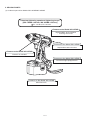
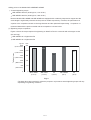
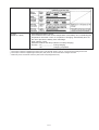
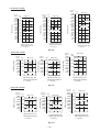
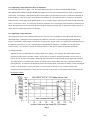
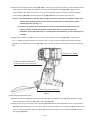
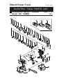
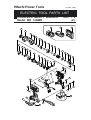
1
MODELS
WH 14DMR, WH 18DMR
WR 14DMR, WR 18DMR
Hitachi
Power Tools
CORDLESS IMPACT DRIVER
WH 14DMR, WH 18DMR
CORDLESS IMPACT WRENCH
WR 14DMR, WR 18DMR
TECHNICAL DATA
AND
SERVICE MANUAL
W
WH 14DMR
LIST Nos. WH 14DMR: G829
WH 18DMR: G831
WR 14DMR
Jul. 2005
WR 14DMR: G830
WR 18DMR: G832
SPECIFICATIONS AND PARTS ARE SUBJECT TO CHANGE FOR IMPROVEMENT
REMARK:
Throughout this TECHNICAL DATA AND SERVICE MANUAL, a symbol(s)
is(are) used in the place of company name(s) and model name(s) of our
competitor(s). The symbol(s) utilized here is(are) as follows:
WH 14DMR
Competitor
Symbol Utilized
P1
Company Name
Model Name
DEWALT
DW054
WH 18DMR
Competitor
Symbol Utilized
P2
Company Name
Model Name
DEWALT
DW056
WR 14DMR
Competitor
Symbol Utilized
P3
Company Name
Model Name
DEWALT
DW055
WR 18DMR
Competitor
Symbol Utilized
P4
Company Name
Model Name
DEWALT
DW057
CONTENTS
Page
1. PRODUCT NAME ........................................................................................................................... 1
2. MARKETING OBJECTIVE ............................................................................................................. 1
3. APPLICATIONS .............................................................................................................................. 1
4. STANDARD EQUIPMENT .............................................................................................................. 1
5. SELLING POINTS .......................................................................................................................... 2
5-1. Selling Points Descriptions ............................................................................................................. 4
6. SPECIFICATIONS .......................................................................................................................... 6
6-1. Specifications .................................................................................................................................. 6
6-2. Optional Accessories .................................................................................................................... 10
7. COMPARISONS WITH SIMILAR PRODUCTS ............................................................................ 13
7-1. Specification Comparisons (Cordless Impact Driver) ................................................................... 13
7-2. Specification Comparisons (Cordless Impact Wrench) ................................................................ 14
7-3. Tightening Torque ......................................................................................................................... 15
7-4. Tightening Time ............................................................................................................................ 20
7-5. Number of Screws or Bolts Driven ................................................................................................ 21
8. PRECAUTIONS IN SALES PROMOTION ................................................................................... 22
8-1. Safety Instructions ........................................................................................................................ 22
8-2. Tightening Torque Inspection Prior to Operation .......................................................................... 25
8-3. Tightening Torque Variation .......................................................................................................... 25
8-4. Suggestions and Precautions for the Efficient Use of the Charger ............................................... 26
9. OTHER PRECAUTIONS .............................................................................................................. 27
10. REPAIR GUIDE .......................................................................................................................... 28
10-1. Precautions in Disassembly and Reassembly ............................................................................ 28
10-2. Precautions in Disassembly and Reassembly of Battery Charger ............................................. 37
11. STANDARD REPAIR TIME (UNIT) SCHEDULES...................................................................... 38
For Models WH 14DMR/WH 18DMR ................................................................................................... 38
For Models WR 14DMR/WR 18DMR ................................................................................................... 39
Assembly Diagram for WH 14DMR
Assembly Diagram for WH 18DMR
Assembly Diagram for WR 14DMR
Assembly Diagram for WR 18DMR
1. PRODUCT NAME
Hitachi Cordless Impact Driver, Model WH 14DMR, WH 18DMR
Hitachi Cordless Impact Wrench, Model WR 14DMR, WR 18DMR
2. MARKETING OBJECTIVE
The current Model WH 12DM2, developed under the concept for "more compact, powerful and convenient model",
has been highly evaluated. However, the market is becoming fiercely competitive due to a price war of the 9.6-V,
12-V, 14.4-V and 18-V impact driver/wrench series. To address the severe situation, we have developed the new
high-performance impact driver/wrench series Models WH 14DMR, WH 18DMR, WR 14DMR and WR 18DMR
under the same concept as the current Model WH 12DM2. These new models can take on the low-price
competitors.
3. APPLICATIONS
• Tightening/loosening of small screws, tapping screws, wood screws, bolts, nuts, etc.
• Drilling into wood and various other materials (with use of optional accessory drill chuck adapter).
[Applicable Markets]
• Wood-product assembly: Tightening/loosening of wood screws
• Construction industry: Assembly of scaffolding, roofing, aluminum sashes, fencing, etc.; removal of plastic cones
from concrete forms, mounting/removal of form ties; drilling into the wood frames of concrete forms, etc.
• Manufacturing industry: Assembly work for automobiles, rolling stock, shipbuilding, agricultural machinery and
tools, industrial machines, steel furniture, etc.
• Utility industry: Assembly and installation of electric equipment, plumbing facilities, air conditioning (duct
assembly etc.), sanitary fixtures and various other facilities.
• Service industry: General repair work; installation of advertising aids, automobile repair, assembly of garages
and carports storage sheds, etc.
• Various other assembly, construction or repair facilities
4. STANDARD EQUIPMENT
Models WH 14DMR/WR 14DMR
(1) 2BGK specification: Two EB 14B batteries (NiCd, capacity 2.0 Ah), UC 18YG charger and case
(2) 2BFK specification: Two EB 14B batteries (NiCd, capacity 2.0 Ah), UC 14YFA charger and case
(3) 2HFK specification: Two EB 1426H or EB 1430H batteries (NiMH, capacity 2.6 Ah or 3.0 Ah), UC14YFA charger
and case
Models WH 18DMR/WR 18DMR
(1) 2BLGK specification: Two EB 1820BL batteries (NiCd, capacity 2.0 Ah), UC 18YG charger and case
(2) 2BLFK specification: Two EB 1820BL batteries (NiCd, capacity 2.0 Ah), UC 24YFA charger and case
(3) 2HLFK specification: Two EB 1826HL or EB 1830HL batteries (NiMH, capacity 2.6 Ah or 3.0 Ah), UC 24YFA charger
and case
--- 1 ---
5. SELLING POINTS
(1) Cordless impact driver Models WH 14DMR/WH 18DMR
Class-top tightening speed and tightening torque
[WH 14DMR: 140 N•m, WH 18DMR: 150 N•m]
P1: 130 N•m, P2: 132 N•m
Common to the Model WH 12DM2
High durability, dust resistance
and long service life
Common to the Model WH 12DM2
Replaceable carbon brushes
Common to the Model WH 12DM2
Protector is standard.
Common to the Model WH 12DM2
Convenient light equipped hook
Common to the Model WH 12DM2
Advanced case
--- 2 ---
(2) Cordless impact wrench Models WR 14DMR/WR 18DMR
Class-top tightening torque
[WR 14DMR: 200 N•m, WR 18DMR: 220 N•m]
P3: 175 N•m, P4: 186 N•m
Common to the Model WH 12DM2
High durability, dust resistance
and long service life
Common to the Model WH 12DM2
Replaceable carbon brushes
Common to the Model WH 12DM2
Protector is standard.
Common to the Model WH 12DM2
Convenient light equipped hook
Common to the Model WH 12DM2
Advanced case
--- 3 ---
5-1. Selling Points Descriptions
Refer to pages 4 through 10 of Technical Data and Service Manual for the Model WH 12DM2 for common selling
points.
Selling points of the Models WH 14DMR/WH 18DMR
Class-top tightening speed and torque
WH 14DMR: 140 N•m (1430 kgf•cm, 1240 in-lbs.)
WH 18DMR: 150 N•m (1530 kgf•cm, 1330 in-lbs.)
Both the Models WH 14DMR and WH 18DMR are equipped with a relatively inexpensive magnet and the
entire length is significantly shorter than the previous models respectively. However, the performance is
superior to the competitors thanks to the large hammer and the optimized impact timing. Comparison of
measured data with the previous model and the competitors is shown below.
1
Tightening time comparison
Figure 1 shows the time required for tightening a wood screw (5.3 mm dia. x 120 mm length) into a lauan
workpiece.
WH 14DMR: 10 % higher than P1
WH 18DMR: 15 % higher than P2
Slow
Fast
Voltage
Model
14.4
HITACHI WH 14DMR
14.4
HITACHI WH 14DM
4
8
6
6.1 sec.
7.1 sec.
5.7 sec.
HITACHI WH 18DMR
18
(sec.)
6.5 sec.
P1
14.4
18
2
6.1 sec.
P2
Fig. 1 Tightening time comparison
* Tightening time may vary depending on hardness of the workpiece, ambient temperature, characteristics
of the battery, etc.
Tightening torque comparison
Figure 2 shows the torque required for
tightening an M14 high-strength tension
bolt in 3 seconds with a hexagon socket
(40 mm long).
WH 14DMR: 10 % higher than P1
WH 18DMR: 15 % higher than P2
Tightening torque
2
kgf . cm
N.m
1800 (1562 in-lbs.)
180
1600 (1389 in-lbs.)
1400 (1215 in-lbs.)
160
140
1200 (1042 in-lbs.)
1000 (868 in-lbs.)
120
100
800 (694 in-lbs.)
600 (521 in-lbs.)
80
60
400 (347 in-lbs.)
40
200 (174 in-lbs.)
20
0
150
162
155
140
137
WH 14DMR WH 14DM
P1
WH 18DMR
Fig. 2 Tightening torque comparison
--- 4 ---
P2
Selling points of the Models WR 14DMR/WR 18DMR
Powerful tightening torque
WR 14DMR: 200 N.m (2040 kgf.cm, 1770 in-lbs.)
WR 18DMR: 220 N.m (2245 kgf.cm, 1950 in-lbs.)
Both the Models WR 14DMR and WR 18DMR are equipped with a relatively inexpensive magnet and the
entire length is significantly shorter than the previous models respectively. However, the performance is
superior to the competitors thanks to the large hammer and the optimized impact timing. Comparison of
measured data with the previous model and the competitors is shown below.
(1) Tightening torque comparison
Figure 3 shows the torque required for tightening an M16 F10T bolt in 3 seconds with a hexagon socket
(40 mm long).
WR 14DMR: 25 % higher than P3
WR 18DMR: 20 % higher than P4
kgf.cm
2500
(2710 in-lbs.)
N.m
250
Tightening torque
232
2000
(1736 in-lbs.)
200
1500
(1302 in-lbs.)
150
1000
(868 in-lbs.)
100
500
(434 in-lbs.)
50
0
0
242
238
207
182
WR 14DMR
(14.4 V)
WR 14DM
(14.4 V)
P3
(14.4 V)
WR 18DMR
(18 V)
P4
(18 V)
Fig. 3
* The data above are intended for reference purposes only because actual tightening torque will vary
depending on tightening conditions.
--- 5 ---
6. SPECIFICATIONS
6-1. Specifications
Models WH 14DMR/WR 14DMR
Model
Cordless impact driver
WH 14DMR
Cordless impact wrench
WR 14DMR
Small screw M4 --- M10 (5/32" --- 3/8")*1
Ordinary bolt M6 --- M14 (1/4" --- 9/16")
High-strength bolt M6 --- M12 (1/4" --- 15/32")
Ordinary bolt M10 --- M16 (3/8" --- 5/8")
High-strength bolt M8 --- M14 (5/16" --- 9/16")
140 N m (1430 kgf cm, 1240 in-lbs.)*2
200 N m (2040 kgf cm, 1770 in-lbs.)*3
6.35 mm (1/4") Bit holder
12.7 mm (1/2") Square drive
Item
Capacity
Tightening torque
•
Tip condition
•
Type of motor
Fan cooled rare-earth magnet motor
Enclosure
Main body: Polyamide resin + elastomer
Aluminum alloy die casting
Elastomer
Storage battery: Polyamide resin (black)
Charger: ABS resin (black)
•
• • • • • •
• • • • • • • • •
• • • • • • • • • • • • • • • • • • • • • • • • • • • • • • • • •
•
Housing
Hammer case
Protector
Type of switch
Trigger switch with forward/reverse changeover pushing button (with brake)
Handle configuration
T-type
No-load rotational speed
0 --- 2,600 /min
Impact rate
0 --- 3,200 /min
Weight
Main body
1.8 kg (3.9 lbs.) (Includes battery)*4
Battery
0.86 kg (1.9 lbs.)
Overall length x height
162 mm (6-3/8") x 236 mm (9-19/64")
Center height
27 mm (1-1/16")
Battery
(Type EB 14B)
Sealed cylindrical nickel-cadmium batteries
Nominal voltage: DC 14.4 V
Nominal life: Charging/discharging approximately 300 cycles
(in the case of the Model UC 18YG)
Nominal capacity: 2.0 Ah
Battery
(Type EB 1426H/
EB 1430H)
Sealed cylindrical nickel-metal hydride batteries
Nominal voltage: DC 14.4 V
Nominal life: Charging/discharging approximately 500 cycles
(in the case of the Model UC 14YFA)
Nominal capacity: 2.6 Ah/3.0 Ah
Charger
(Model UC 14YFA)
Charger power source: single-phase AC, 50/60 Hz
Voltage: Depending on the order specification
Power input: 56 W
Charging system: Constant current charge with feedback control
Overcharge protection system: (1) Battery voltage detection ( 2V system)
Battery temperature detection (dT/dt system) for
Ni-MH battery
(2) Battery surface temperature detection
(thermistor)
(3) 120-minute timer
Output voltage: 7.2 V --- 14.4 V
Output current: 2.6 A
Charging time: Approx. 50 minutes (for BL-type EB 14B battery at 20 ûC)
Approx. 60 minutes (for type EB 1426H battery at 20 ûC)
Approx. 70 minutes (for HL-type EB 1430H battery at 20 ûC)
Product weight: 0.6 kg
Operable ambient temperature range: 0 ûC --- 40 ûC
The maximum allowable temperature of the EB 14B type battery is 55 ûC and the
EB 1426H or EB 1430H type battery is 45 ûC.
--- 6 ---
167 mm (6-37/64") x 236 mm (9-19/64")
Charger
(Model UC 18YG)
Overcharge prevention circuit:
A thermostat monitors the surface temperature of the battery and, on detecting the
temperature rise which occurs on completion of charging, automatically turns off
the unit to prevent the battery from overcharge.
Input capacity: 70 W
Indication method: Pilot lamp indicator of battery charging
Function : On ....................... During charging
Off ....................... Charging completed
*1: In the case of tapping screws and wood screws, a minimum of M3 (1/8") is possible.
*2: This torque is based on tightening an M12 (9/16") bolt (strength grade: 12.9) for 3 seconds with a hexagonal socket.
*3: This torque is based on tightening an M16 (5/8") bolt (F10T) for 3 seconds with a hexagonal socket.
*4: Main body does not include accessory tools and hook (hexagonal bit etc.).
Pilot lamp indications (Model UC 14YFA)
Red pilot lamp
remains lit or flashes.
Prior to charging
Blinks
During charging
Lit
Charging completed
Blinks
Charging not possible
Flickers
High battery
Green pilot lamp is lit. temperature
0.5 sec ON, 0.5 sec OFF
Stays ON constantly
0.5 sec ON, 0.5 sec OFF
0.1 sec ON, 0.1 sec OFF
Stays ON constantly
Lit
--- 7 ---
Storage battery or charger
is faulty.
Charging not possible
because storage battery
temperature is too high.
Models WH 18DMR/WR 18DMR
Model
Cordless impact driver
WH 18DMR
Cordless impact wrench
WR 18DMR
Small screw M4 --- M10 (5/32" --- 3/8")*1
Ordinary bolt M6 --- M14 (1/4" --- 9/16")
High-strength bolt M6 --- M12 (1/4" --- 15/32")
Ordinary bolt M10 --- M16 (3/8" --- 5/8")
High-strength bolt M8 --- M14 (5/16" --- 9/16")
150 N m (1530 kgf cm, 1330 in-lbs.)*2
220 N m (2245 kgf cm, 1950 in-lbs.)*3
6.35 mm (1/4") Bit holder
12.7 mm (1/2") Square drive
Item
Capacity
Tightening torque
•
Tip condition
•
Type of motor
Fan cooled rare-earth magnet motor
Enclosure
Main body: Polyamide resin + elastomer
Aluminum alloy die casting
Elastomer
Storage battery: Polyamide resin (black)
Charger: ABS resin (black)
•
• • • • • •
• • • • • • • • •
• • • • • • • • • • • • • • • • • • • • • • • • • • • • • • • • •
•
Housing
Hammer case
Protector
Type of switch
Trigger switch with forward/reverse changeover pushing button (with brake)
Handle configuration
T-type
No-load rotational speed
0 --- 2,600 /min
Impact rate
0 --- 3,200 /min
Weight
Main body
2.0 kg (4.4 lbs.) (Includes battery)*4
Battery
1.04 kg (2.2 lbs.)
Overall length x height
162 mm (6-3/8") x 236 mm (9-19/64")
Center height
27 mm (1-1/16")
Battery
(Type EB 1820L)
Sealed cylindrical nickel-cadmium batteries
Nominal voltage: DC 18 V
Nominal life: Charging/discharging approximately 300 cycles
(in the case of the Model UC 18YG)
Nominal capacity: 2.0 Ah
Battery
(Type EB 1826HL/
EB 1830HL)
Sealed cylindrical nickel-metal hydride batteries
Nominal voltage: DC 18 V
Nominal life: Charging/discharging approximately 500 cycles
(in the case of the Model UC 24YFA)
Nominal capacity: 2.6 Ah/3.0 Ah
Charger
(UC 24YFA)
Overcharge protection system:
(1) Battery voltage detection ( 2V system) for Ni-Cd battery
Mi-MH battery temperature detection (dT/dt system) for Ni-MH battery
(2) Battery surface temperature detection (thermostat or thermistor)
(3) 120-minute timer
Power input: 90 W
Charging time: Approx. 50 minutes [for type EB 1820L battery at 20ûC (68ûF)]
Approx. 60 minutes [for type EB 1826HL battery at 20ûC (68ûF)]
Approx. 70 minutes [for type EB 1830HL battery at 20ûC (68ûF)]
Operable ambient temperature range: 0ûC --- 40ûC (32ûF --- 104ûF)
The maximum allowable temperature of the EB 1820L battery is 60ûC (140ûF) and
the type EB 1826HL or EB 1830HL battery is 45ûC (113ûF).
--- 8 ---
167 mm (6-37/64") x 236 mm (9-19/64")
Indication method of battery charging function:
Charger
(Model UC 18YG)
Overcharge prevention circuit:
A thermostat monitors the surface temperature of the battery and, on detecting the
temperature rise which occurs on completion of charging, automatically turns off
the unit to prevent the battery from overcharge.
Input capacity: 70 W
Indication method: Pilot lamp indicator of battery charging
Function : On ....................... During charging
Off ....................... Charging completed
*1: In the case of tapping screws and wood screws, a minimum of M3 (1/8") is possible.
*2: This torque is based on tightening an M14 (9/16") bolt (strength grade: 12.9) for 3 seconds with a hexagonal socket.
*3: This torque is based on tightening an M16 (5/8") bolt (F10T) for 3 seconds with a hexagonal socket.
*4: Main body does not include accessory tools and hook (hexagonal bit etc.).
--- 9 ---
6-2. Optional Accessories
(1) Optional accessories for the Models WH 14DMR/WH 18DMR
• Plus driver bit
50 mm (2")
Bit No.
Code No.
No. 2
992671
No. 3
992672
• Hexagon socket
Stamped figures
B
L
Stamped figures
L
(mm)
B
(mm)
Code No.
5 mm Hexagon socket
8
65 (2-9/16")
8 (5/16")
996177
6 mm Hexagon socket
10
65 (2-9/16")
10 (3/8")
985329
5/16" Hexagon socket
12
65 (2-9/16")
12 (15/32")
996178
8 mm Hexagon socket
13
65 (2-9/16")
13 (1/2")
996179
10 mm Hexagon socket (small type)
14
65 (2-9/16")
14 (9/16")
996180
10 mm Hexagon socket
16
65 (2-9/16")
16 (5/8")
996181
10 mm Hexagon socket
17
65 (2-9/16")
17 (21/32")
996182
1/2" Hexagon long socket
21
166 (6-17/32")
21 (53/64")
996197
Part name
14 mm dia.
(35/64")
• Woodworking drill bit
(Code No. 959183)
83 mm (3-17/64")
• Drill chuck adaptor set
(Code No. 996195)
The drill chuck adaptor set permits mounting of various types of locally-available drill bits for a variety of drilling
operations.
--- 10 ---
(2) Optional accessories for the Models WR 14DMR/WR 18DMR
• Each dimension and applicable bolt for each hexagon socket
Square
drive
dimension
Sq
Shape C
Nominal diameter of applicable bolts
Part
name
Code
No.
ISO
(Highstrength)
10 mm 944291
ISO
(Ordinary)
Hexagon socket
13 mm 873539
Socket primary dimensions (mm)
L1
D1
B
40 (1-9/16")
8 (5/16")
18 (23/32")
M 8 (5/16") W 5/16" 12 (15/32") B
40 (1-9/16")
8 (5/16")
20 (25/32")
13 (1/2")
B
40 (1-9/16")
9 (11/32") 25 (1")
14 (9/16")
B
40 (1-9/16")
9 (11/32") 25 (1")
32 (1-1/4")
8 (5/16")
34 (1-11/32")
9 (11/32") 28 (1-3/32")
10 (3/8")
M 8 (5/16")
14 mm 873540
M 10 (3/8")
17 mm 873536
M 10 (3/8") M 12 (15/32")
19 mm 873624
Inch
screw
Dihedral
width
H (mm)
L
M 6 (1/4")
12 mm 873632
12.7 mm
(1/2")
ISO
(Small type)
Shape D
Shape
Shape B
W 3/8" 17 (21/32") C
M 12 (15/32") M 14 (9/16") W 7/16" 19 (23/32") C
21 mm 873626
W 1/2" 21(53/64")
28 (1-3/32")
D
36 (1-13/32")
10 (3/8")
32 (1-1/4")
22 mm 873627 M 12 (15/32") M 14 (9/16") M 16 (5/8")
22 (7/8")
D
40 (1-9/16")
14 (9/16")
35 (1-3/8")
24 mm 873629
24 (15/16") D
40 (1-9/16")
15 (9/16")
38 (1-1/2")
D
40 (1-9/16")
15 (9/16")
38 (1-1/2")
27 (1-1/16") D
40 (1-9/16")
16 (5/8")
42 (1-21/32")
M 16 (5/8") M 18 (23/32")
26 mm 873630
27 mm 985195
W 5/8" 26 (1")
M 16 (5/8") M 18 (23/32")
M 20
• Each dimension and applicable bolt for each long socket
Shape D
Shape B
--- 11 ---
Nominal diameter of applicable bolts
Part
name
Code
No.
ISO
(Highstrength)
ISO
ISO
(Ordinary) (Small type)
M 8 (5/16")
12 mm 955138
14 mm 955140
Long socket
W 5/16" 12 (15/32")
L
L1
L2
D1
52 (2-3/64") 20 (25/32") 34(1-11/32") 20 (25/32")
13 (1/2")
B
52 (2-3/64") 20 (25/32") 34(1-11/32") 21.5 (53/64")
M 10 (3/8")
14 (9/16")
B
52 (2-3/64") 20 (25/32") 34(1-11/32") 22 (7/8")
17 mm 955141
M 10 (3/8")
M 12 (15/32") W 3/8"
17 (21/32")
B
52 (2-3/64") 24 (15/16") 34(1-11/32") 25 (1")
17 mm 955149
M 10 (3/8")
M 12 (15/32") W 3/8"
17 (21/32")
B
75 (2-15/16") 24 (15/16") 57(2-1/4")
19 mm 955142
M 12 (15/32") M 14 (9/16")
W 7/16" 19 (23/32")
B
52 (2-3/64") 24 (15/16") 34(1-11/32") 28 (1-3/32")
19 mm 955150
M 12 (15/32") M 14 (9/16")
W 7/16" 19 (23/32")
B
75 (2-15/16") 24 (15/16") 57(2-1/4")
25 (1")
28 (1-3/32")
21 mm 955143
W 1/2"
21 (53/64")
D
52 (2-3/64") 24 (15/16") 34(1-11/32") 31 (1-7/32")
21 mm 955151
W 1/2"
21 (53/64")
D
75 (2-15/16") 24 (15/16") 57(2-1/4")
21 mm 991480
W 1/2"
21 (53/64")
D
125 (4-47/51") 24 (15/16") 107 (4-7/32") 31 (1-7/32")
22 (7/8")
D
52 (2-3/64") 24 (15/16") 34(1-11/32") 32.5 (1-9/32")
24 (15/16")
D
52 (2-3/64") 25 (63/64") 34(1-11/32") 34 (1-11/32")
26 (1")
D
75 (2-15/16") 25 (63/64") 57 (2-1/4")
22 mm 955144 M 12 (15/32") M 14 (9/16") M 16 (5/8")
M 16 (5/8")
24 mm 955146
M 18 (23/32")
26 mm 955147
• Bit adaptor
Socket primary dimensions (mm)
B
M 8 (5/16")
13 mm 955139
12.7 mm
(1/2")
Inch
screw
Dihedral
width
H (mm)
Shape
Square
drive
dimension
Sq
W 5/8"
31 (1-7/32")
38 (1-1/2")
(Code No. 991476)
6.35 mm (1/4")
12.7 mm (1/2")
Part name Overall length Code No.
(mm)
Plus hd.
45 (1-25/32")
955229
driver bit
70 (2-3/4")
955654
No.2
Plus hd.
45 (1-25/32")
955230
driver bit
70 (2-3/4")
955655
No.3
13.5 mm dia.
(17/32")
45 mm (1-25/32")
• Extension bar [Overall length 100 mm (3-15/16") ] (Code No. 873633)
• Universal joint (Code No. 992610)
• Socket ass'y for duct
• EW-14R corner attachment (Code No. 9329-9001)
--- 12 ---
Dihedral width of
applicable bolts
Code No.
12 (15/32")
993658
13 (1/2")
992613
14 (9/16")
992615
7. COMPARISONS WITH SIMILAR PRODUCTS
7-1. Specification Comparisons (Cordless Impact Driver)
Maker
Model
P2
WH 14DM
WH 18DMR
Small screw
M 4 --- M 10 1
(5/32" --- 3/8")*
M 4 --- M 10
1
(5/32" --- 3/8")*
M 4 --- M 10 1
(5/32" --- 3/8")*
Ordinary bolt
M 6 --- M 14
(1/4" --- 9/16")
M 6 --- M 14
(1/4" --- 9/16")
M 6 --- M 14
(1/4" --- 9/16")
High-strength bolt
M 6 --- M 12
(1/4" --- 15/32")
M 6 --- M 12
(1/4" --- 15/32")
M 6 --- M 12
(1/4" --- 15/32")
140
(1430 kgf• cm,
1240 in-lbs.)
145
(1480 kgf• cm,
1280 in-lbs.)
130
(1330 kgf• cm,
1150 in-lbs.)
150
(1530 kgf• cm,
1330 in-lbs.)
132
(1350 kgf• cm,
1170 in-lbs.)
No-load rotation speed min-1
0 --- 2,600
0 --- 2,600
0 --- 2,400
0 --- 2,600
0 --- 2,400
-1
0 --- 3,200
0 --- 3,200
0 --- 3,000
0 --- 3,200
0 --- 3,000
kg
1.8 (3.9 lbs.)
1.8 (3.9 lbs.)
1.9 (4.1 lbs.)
2.0 (4.4 lbs.)
2.2 (4.7 lbs.)
Nm
150
(1531 kgf• cm,
1329 in-lbs.)
155
(1582 kgf• cm,
1373 in-lbs.)
137
(1408 kgf• cm,
1222 in-lbs.)
162
(1653 kgf• cm,
1435 in-lbs.)
140
(1429 kgf• cm,
1240 in-lbs.)
No-load rotation speed min-1
0 --- 2,610
0 --- 2,650
0 --- 2,470
0 --- 2,600
0 --- 2,490
min-1
0 --- 3,190
0 --- 3,210
0 --- 2,800
0 --- 3,170
0 --- 2,840
Capacity
Catalog specifications
P1
WH 14DMR
Item
Max. tightening
torque
Nm
•
min
Impact rate
3
Main body weight *
Max. tightening
torque *2
Measured figures
HITACHI
HITACHI
•
Impact rate
Overall length
x height
167 x 232
162 x 236
167 x 234
162 x 236
179 x 236
mm
(6-3/8" x 9-19/64") (7-3/64" x 9-19/64") (6-37/64" x 9-9/64") (6-3/8" x 9-19/64") (6-37/64" x 9-7/32")
27 (1-1/16")
27 (1-1/16")
28.5 (1-1/8")
27 (1-1/16")
28.5 (1-1/8")
kg 1.87 (4.1 lbs.)
Main body weight *
No-load sound
dB(A)
72
pressure level
Tool tip mounting system
Driver chuck
1.89 (4.1 lbs.)
1.85 (4.1 lbs.)
2.09 (4.5 lbs.)
2.19 (4.7 lbs.)
71
76
72
76
Driver chuck
Driver chuck
Driver chuck
Driver chuck
Type of switch
Variable speed
switch with
forward/reverse
changeover lever
Variable speed
switch with
forward/reverse
changeover lever
Variable speed
switch with
forward/reverse
changeover lever
Variable speed
switch with
forward/reverse
changeover lever
Variable speed
switch with
forward/reverse
changeover lever
Type of motor
DC magnet
DC magnet
DC magnet
DC magnet
14.4
14.4
14.4
18
18
32
30
28
26
24
Type
EB 14B, EB 1426H
or EB1430H
EB 14B or EB1430H
DW9091
EB 1820L, EB 1830HL
or EB1826HL
DW9096
Nominal capacity
Ah
EB 14B: 2.0
EB1426H: 2.6
EB 1430H: 3.0
EB 14B: 2.0
EB 1430H: 3.0
V
14.4
14.4
0 --- 40
0 --- 40
UC 14YFA or
UC 18YG
UC 14YFA: 56
UC 18YG: 70
UC 14YFA: 7.2 --- 14.4
UC 18YG: 7.2 --- 18
UC 14YF2 or
UC 14YFA
UC 14YF2: 44
UC 14YFA: 56
mm
Center height
3
V
Current
A
Battery
Voltage
Nominal voltage
Charger
Ambient temperature ûC
Model
Power input capacity VA
Recharging voltage
Standard accessories
V
• Plastic tool
case
• Charger
(UC 14YFA or
UC 18YG)
7.2 --- 14.4
• Plastic tool
case
• Charger
(UC 14YF2 or
UC 14YFA)
DC magnet
1.7
EB 1820L: 2.0
EB 1826HL: 2.6
EB 1830HL: 3.0
2.4
14.4
18
18
0 --- 40
DW9107
7.2 --- 14.4
• Plastic tool
case
• Charger
(DW9107)
UC 24YFA or
UC 18YG
UC 24YFA: 90
UC 18YG: 70
UC 24YFA: 7.2 --- 24
UC 18YG: 7.2 --- 18
• Plastic tool
case
• Charger
(UC 24YFA or
UC 18YG)
DW9116
7.2 --- 18
• Plastic tool
case
• Charger
(DW9116)
*1: In the case of tapping screws and wood screws, a minimum of M3 (1/8") is possible.
*2: Max. tightening torque is based on tightening an M14 (9/16") bolt (strength grade: 12.9) for 3 seconds with a hexagon
socket.
*3: Main body weight does not include accessory tools and hook (hexagon bit etc.).
--- 13 ---
7-2. Specification Comparisons (Cordless Impact Wrench)
Maker
Model
P4
WR 14DM
WR 18DMR
M 10 --- M 16
(3/8" --- 5/8")
M 10 --- M 16
(3/8" --- 5/8")
M 10 --- M 16
(3/8" --- 5/8")
M 8 --- M 14
(5/16" --- 9/16")
M 8 --- M 14
(5/16" --- 9/16")
M 8 --- M 14
(5/16" --- 9/16")
200 *1
(2040 kgf• cm,
1770 in-lbs.)
200 *1
(2040 kgf• cm,
1770 in-lbs.)
175
(1780 kgf• cm,
1545 in-lbs.)
220 *1
(2245 kgf• cm,
1950 in-lbs.)
186
(1900 kgf• cm,
1650 in-lbs.)
No-load rotation speed min-1
0 --- 2,600
0 --- 2,300
0 --- 2,400
0 --- 2,600
0 --- 2,400
min-1
0 --- 3,200
0 --- 3,000
0 --- 3,000
0 --- 3,200
0 --- 3,000
kg
1.8 (3.9 lbs.)
1.8 (3.9 lbs.)
1.9 (4.2 lbs.)
2.0 (4.4 lbs.)
2.2 (4.7 lbs.)
Nm
232
(2366 kgf• cm,
2054 in-lbs.)
238
(2429 kgf• cm,
2108 in-lbs.)
182
(1857 kgf• cm,
1580 in-lbs.)
242
(2469 kgf• cm,
2100 in-lbs.)
207
(2112 kgf• cm,
1797 in-lbs.)
No-load rotation speed min-1
0 --- 2,610
0 --- 2,350
2,470
0 --- 2,600
0 --- 2,490
-1
0 --- 3,290
167 x 236
0 --- 3,210
184 x 236
0 --- 3,010
168 x 232
0 --- 3,270
167 x 236
0 --- 3,050
168 x 234
Capacity
Catalog specifications
P3
WR 14DMR
Item
Ordinary bolt
High-strength bolt
Max. tightening
torque
Impact rate
3
Main body weight *
Max. tightening
torque
Measured figures
HITACHI
HITACHI
Nm
•
•
Impact rate
Overall length
x height
min
Center height
mm
27 (1-1/16")
27 (1-1/16")
28.5 (1-1/8")
27 (1-1/16")
28.5 (1-1/8")
kg
1.88 (4.1 lbs.)
1.89 (4.1 lbs.)
1.87 (4.1 lbs.)
2.09 (4.5 lbs.)
2.18 (4.7 lbs.)
dB(A)
72
70
76
72
76
3
Main body weight *
No-load sound
pressure level
mm
Tool tip mounting system
(6-37/64" x 9-19/64") (7-1/4" x 9-19/64") (6-39/64" x 9-9/64") (6-37/64" x 19/64") (6-39/64" x 9-7/32")
12.7 mm
12.7 mm
12.7 mm
12.7 mm
12.7 mm
(1/2" square drive) (1/2" square drive) (1/2" square drive) (1/2" square drive) (1/2" square drive)
Plunger type
Plunger type
Plunger type
Plunger type
Plunger type
Type of switch
Trigger switch with
forward/reverse
changeover pushing
button with brake
and variable
Trigger switch with
forward/reverse
changeover pushing
button with brake
and variable
Trigger switch with
forward/reverse
changeover pushing
button with brake
and variable
Trigger switch with
forward/reverse
changeover pushing
button with brake
and variable
Trigger switch with
forward/reverse
changeover pushing
button with brake and
variable
Type of motor
DC magnet
DC magnet
DC magnet
DC magnet
18
18
DC magnet
Voltage
V
14.4
14.4
14.4
Current
A
27
26
26
23
22
DW9091
EB 1820L, EB 1230HL
or EB1826HL
DW9096
EB 14B: 2.0
EB 1430H: 3.0
1.7
EB 1820BL: 2.0
EB 1826HL: 2.6
EB 1830HL: 3.0
2.4
14.4
18
18
DW9107
EB 14B, EB 1430H
or EB1426H
Battery
Type
Nominal capacity
Nominal voltage
Ah
EB 14B: 2.0
EB1426H: 2.6
EB 1430H: 3.0
V
14.4
14.4
0 --- 40
0 --- 40
0 --- 40
UC 14YFA or
UC 18YG
UC 14YF2
UC 24YFA or
UC 18YG
UC 14YFA: 56
UC 18YG: 70
UC 14YFA: 7.2 --- 14.4
UC 18YG: 7.2 --- 18
UC 14YF2: 44
UC 14YFA: 56
Charger
Ambient temperature ûC
Model
Power input capacity VA
Recharging voltage
Standard accessories
EB 14B or EB1430H
V
• Plastic tool
case
• Charger
(UC 14YFA or
UC 18YG)
7.2 --- 14.4
7.2 --- 14.4
• Plastic tool
• Plastic tool
case
case
• Charger
• Charger
(UC 14YF2 or (DW9107)
UC 14YFA)
UC 24YFA: 90
UC 18YG: 70
UC 24YFA: 7.2 --- 24
UC 18YG: 7.2 --- 18
DW9116
7.2 --- 18
• Plastic tool
• Plastic tool
case
case
Charger
•
• Charger
(UC 24YFA or (DW9116)
UC 18YG)
*1: Max. tightening torque is based on tightening an M 16 (5/8") bolt (F10T) for 3 seconds with a hexagon socket.
*3: Main body weight does not include accessory tools and hook (hexagon bit etc.).
--- 14 ---
7-3. Tightening Torque
7-3-1. Tightening torque characteristic comparisons
(1) Impact driver (14.4 V)
kgf.cm
1800 (1562 in-lbs.)
Test conditions
Bolt: M14 x 50 mm, high-strength bolt
Steel plate: SS34P
Thickness 25 mm
Accessory tool: Hexagon socket
(length: 40 mm,
width across flat: 19 mm)
1600 (1389 in-lbs.)
160
1400 (1215 in-lbs.)
140
1200 (1042 in-lbs.)
120
1000 (868 in-lbs.)
100
800 (694 in-lbs.)
80
600 (521 in-lbs.)
60
400 (347 in-lbs.)
40
200 (174 in-lbs.)
20
0
0
0
WH 14DMR
WH 14DM
N.m
180
P1
0
1
3 (sec.)
2
(2) Impact driver (18 V)
kgf.cm
1800 (1562 in-lbs.)
1600 (1389 in-lbs.)
160
1400 (1215 in-lbs.)
140
1200 (1042 in-lbs.)
120
1000 (868 in-lbs.)
100
800 (694 in-lbs.)
80
600 (521 in-lbs.)
60
400 (347 in-lbs.)
40
200 (174 in-lbs.)
20
0
0
0
WH 18DMR
N.m
180
Test conditions
Bolt: M14 x 50 mm, high-strength bolt
Steel plate: SS34P
Thickness 25 mm
Accessory tool: Hexagon socket
(length: 40 mm,
width across flat: 19 mm)
P2
0
1
3 (sec.)
2
--- 15 ---
(3) Impact wrench (14.4 V)
WR 14DM
N.m
250
kgf.cm
2500 (2170 in-lbs.)
200
2000 (1736 in-lbs.)
1500 (1302 in-lbs.)
150
1000 (868 in-lbs.)
100
500 (434 in-lbs.)
50
0
Test conditions
Bolt: M16 x 55 mm (5/8" x 2-5/32") (F10T)
Steel plate: Mild steel
Thickness 25 mm
Accessory tool: Hexagon socket ass'y
0
0
WR 14DMR
P3
0
1
3
2
(sec.)
(4) Impact wrench (18 V)
3000 (2604 in-lbs.)
2500 (2170 in-lbs.)
250
2000 (1736 in-lbs.)
200
1500 (1302 in-lbs.)
150
1000 (868 in-lbs.)
100
500 (434 in-lbs.)
50
0
WR 18DMR
N.m
300
kgf.cm
0
0
Test conditions
Bolt: M16 x 55 mm (5/8" x 2-5/32") (F10T)
Steel plate: Mild steel
Thickness 25 mm
Accessory tool: Hexagon socket ass'y
P4
0
1
2
3 (sec.)
--- 16 ---
7-3-2. Screw diameter and appropriate tightening torque
Generally speaking, the appropriate tightening torque for a screw can be determined by the strength grade of the
screw and the material tightened. Tables 1 and 2, and Fig. 4 below list data relative to the strength grade of
various screws and the appropriate tightening torque. For further reference, appropriate tightening torque is
calculated with the following formula. Study and use this formula for accurate selection of tightening torque.
T=k d p
•
•
T: Appropriate tightening torque (kgf cm)
•
d: Nominal diameter for the screw (mm)
p: Recommended axial tightening force to be applied to the screw (kgf)
p=rated axial stress (kgf/cm2) x 0.8 x effective sectional area of the thread (mm2)
k: Torque coefficient (0.17)
• Strength grade and rated axial stress of threads
Table 1
Strength grade
4.8
6.8
8.8
12.9
Rated axial stress (kgf/mm2)
29.1
43.7
58.2
95
Material
Mild steel
Alloy steel including Ni, Mn, Cr, etc.
None
Processed-hard material
Heat treatment
• Diameter and effective sectional areas of threads
Table 2
Kind of thread (x pitch)
M5 x 0.8 mm M6 x 1 mm
(3/16")
(1/4")
Effective sectional area
of thread (mm2)
14.2
M8 x 1.25 mm M10 x 1.5 mm M12 x 1.75 mm M14 x 2 mm M16 x 2 mm
(15/32")
(9/16")
(5/16")
(3/18")
(5/8")
20.1
36.6
58.0
84.3
115
157
Appropriate tightening torque
• Thread diameter and appropriate tightening torque
kgf.cm
3000
(2604 in-lbs.)
N.m
300
2500
(2170 in-lbs.)
250
2000
(1736 in-lbs.)
200
1500
(1302 in-lbs.)
150
Strength grade 8.8
(high-strength bolt)
1000
(868 in-lbs.)
100
Strength grade 6.8
(ordinary bolt)
500
(434 in-lbs.)
50
Strength grade 4.8
(ordinary bolt)
0
0
Strength grade 12.9
(high-strength bolt)
6
8
10
12
(5/16")
(3/8")
14
16
(1/4")
(15/32")
(9/16")
(5/8")
Thread diameter
Fig. 4
--- 17 ---
mm
7-3-3. Bolt tightening torque characteristics
Figures 5-1 and 5-2 show relationships between time and tightening torque for individual bolt types and sizes.
While the data are useful for handy reference, actual tightening torque will vary depending on tightening
conditions and other variables. For details, please refer to Para. 8-3, "Tightening Torque Variation".
(Note)
• The term "tightening time" indicates the impact time after the lower surface of the bolt has come in contact with
the material into which it is being tightened.
• In the tightening conditions shown in Figs. 5-1 to 5-4, the screws are being tightened directly into a steel plate;
accordingly, the torque goes up very abruptly in comparison with ordinary bolt tightening conditions.
* The following bolts were utilized:
Ordinary bolt; strength grade 4.8
High-strength bolt; strength grade
12.9
Strength grade is read as follows:
4.8
Yield point or durable force:
(45,500 psi)
Tensile strength of the bolt:
(56,900 psi)
• Model WH 14DMR
kgf . cm
.
(in-lbs.) N m
M10 x 30
1600
(1389)
160
1400 140 High-strength bolt
(1215)
1200 120
(1042)
1000 100
(868)
Tightening torque
Tightening torque
1600
(1389)
N. m
160
80
600
(521)
60
40
400
(347)
200
(174)
20
0
0
80
600
(521)
60
400
(347)
Ordinary bolt
0
1
2
3
Tightening time: sec.
(Steel plate thickness
t = 10 mm))
1600
(1389)
High-strength bolt
1400 140
(1215)
1200 120
(1042)
1000 100
(868)
800
(694)
800
(694)
kgf . cm
(in-lbs.)
M12 x 45
Tightening torque
kgf . cm
(in-lbs.)
N. m
High-strength bolt
1400 140
(1215)
1200 120
(1042)
1000 100
(868)
800
(694)
80
600
(521)
60
40
400
(347)
40
200
(174)
20
200
(174)
20
0
0
0
0
Ordinary bolt
0
1
2
3
Tightening time: sec.
(Steel plate thickness
t = 25 mm))
Fig. 5-1
--- 18 ---
M14 x 50
160
Ordinary bolt
0
1
2
3
Tightening time: sec.
(Steel plate thickness
t = 25 mm))
Model WH 18DMR
kgf . cm
N. m
(in-lbs.)
M10 x 30
M12 x 45
kgf . cm
(in-lbs.)
N. m
1800
(1562)
180
1600
(1389)
160
1600
(1389)
160
140
1400
(1215)
140
1400
(1215)
140
1200
(1042)
120
1200
(1042)
120
1200
(1042)
120
1000
(868)
100
1000
(868)
100
1000
(868)
100
800
(694)
80
800
(694)
80
800
(694)
80
600
(521)
60
600
(521)
60
600
(521)
60
400
(347)
40
400
(347)
40
400
(347)
40
200
(174)
20
200
(174)
20
200
(174)
20
0
0
0
0
0
0
1600
(1389)
160
1400
(1215)
High-strength bolt
Ordinary bolt
1
0
2
High-strength bolt
3
Tightening torque
Tightening torque
kgf . cm
.
(in-lbs.) N m
Tightening torque
•
Ordinary bolt
0
1
2
3
Tightening time: sec.
(Steel plate thickness
t = 25 mm))
Tightening time: sec.
(Steel plate thickness
t = 10 mm))
M14 x 50
High-strength bolt
Ordinary bolt
2
1
0
3
Tightening time: sec.
(Steel plate thickness
t = 25 mm))
Fig. 5-2
Model WR 14DMR
N. m
2000
(1736)
200
1500
(1302)
150
1000
(868)
100
500
(434)
50
0
0
kgf . cm
(in-lbs.)
M10 x 30
High-strength bolt
Ordinary bolt
1
0
2
2000
(1736)
200
1500
(1302)
150
1000
(868)
100
500
(434)
50
0
0
3
M12 x 45
N.m
High-strength bolt
Tightening torque
Tightening torque
kgf . cm
(in-lbs.)
kgf . cm
(in-lbs.)
Tightening torque
•
Ordinary bolt
Tightening time: sec.
(Steel plate thickness
t = 10 mm)
1
0
2
M14 x 45
N.m
2500
(2170)
250
2000
(1736)
200
1500
(1302)
150
1000
(868)
100
500
(434)
50
0
0
3
High-strength bolt
Ordinary bolt
0
2
1
3
Tightening time: sec.
(Steel plate thickness
t = 25 mm)
Tightening time: sec.
(Steel plate thickness
t = 25 mm)
Fig. 5-3
• Model WR 18DMR
N. m
2000
(1736)
200
1500
(1302)
150
1000
(868)
100
500
(434)
50
0
0
(in-lbs.)
M10 x 30
High-strength bolt
Ordinary bolt
0
1
2
3
Tightening time: sec.
(Steel plate thickness
t = 10 mm)
N. m
2000
(1736)
200
1500
(1302)
150
1000
(868)
100
500
(434)
50
0
0
M12 x 45
Ordinary bolt
High-strength bolt
0
1
2
3
Tightening time: sec.
(Steel plate thickness
t = 25 mm)
Fig. 5-4
--- 19 ---
Tightening torque
(in-lbs.)
kgf . cm
Tightening torque
Tightening torque
kgf . cm
kgf . cm
(in-lbs.)
M14 x 50
N. m
2500
(2170)
250
2000
(1736)
200
1500
(1302)
150
1000
(868)
100
500
(434)
50
0
0
High-strength bolt
Ordinary bolt
0
1
2
3
Tightening time: sec.
(Steel plate thickness
t = 25 mm)
7-4. Tightening Time
The performance of the Models WH 14DMR, WH 18DMR, WR 14DMR and WR 18DMR is superior to the
competitors thanks to the large hammer and the optimized impact timing. Tightening time comparison is shown
below. The data below are intended for reference purposes only because actual tightening time will vary
depending on hardness of the workpiece, ambient temperature, characteristics of the battery, etc.
1 Wood screw 5.3 mm dia. x 120 mm length, lauan
Voltage
Fast
Model
14.4
HITACHI WH 14DMR
14.4
HITACHI WH 14DM
14.4
P1
18
HITACHI WH 18DMR
18
P2
Slow
6
4
2
10
8
sec.
6.5 sec.
6.1 sec.
7.1 sec.
5.7 sec.
6.1 sec.
2 Wood screw 4.5 mm dia. x 90 mm length, hemlock spruce
Fast
Voltage
Model
14.4
HITACHI WH 14DMR
14.4
HITACHI WH 14DM
14.4
P1
18
HITACHI WH 18DMR
18
P2
1
Slow
3
2
4
5
sec.
4
5
sec.
2.4 sec.
2.3 sec.
2.4 sec.
2.0 sec.
2.1 sec.
3 Wood screw 4.2 mm dia. x 75 mm length, hemlock spruce
Fast
Voltage
Model
14.4
HITACHI WH 14DMR
1.5 sec.
14.4
HITACHI WH 14DM
1.5 sec.
1
2
14.4
P1
1.5 sec.
18
HITACHI WH 18DMR
1.4 sec.
18
P2
1.4 sec.
--- 20 ---
Slow
3
7-5. Number of Screws or Bolts Driven
7-5-1. Per-charge working capacity comparisons
Test data on the number of screws or bolts which can be driven per battery charge by the new models vs. the
previous models are shown in the table below. Please note that the data below are intended for general reference
only as the number of screws which can be tightened per charge will vary slightly depending on screw tightening
conditions, screw sizes, ambient temperatures and the charging capacity of the battery.
Number of screws or bolts driven (Cordless impact driver)
Model
HITACHI
HITACHI
WH 14DMR
WH 14DM
Tightening condition
P1
HITACHI
WH 18DMR
P2
EB 14B
EB 14B
DW9091
(Nominal capacity:
2.0 Ah)
(Nominal capacity:
2.0 Ah)
(Nominal capacity:
1.7 Ah)
Wood screw
4.0 mm dia. x 50 mm
(soft wood)
640
640
680
1165
1200
Wood screw
4.2 mm dia. x 90 mm
(hard wood)
150
150
140
275
275
Wood screw
5.3 mm dia. x 120 mm
(hard wood)
55
55
40
95
90
1,270
1,270
1,350
2,300
2,375
Battery
Machine screw
(M8 x 16 mm)
--- 21 ---
(Nominal capacity:
2.6 Ah)
DW9096
(Nominal capacity:
2.4 Ah)
8. PRECAUTIONS IN SALES PROMOTION
8-1. Safety Instructions
In the interest of promoting the safest and most efficient use of these tools by all our customers, it is very
important that at the time of sale the salesperson carefully ensures that the buyer seriously recognizes the
importance of the contents of the Handling Instructions, and fully understands the meaning of the precautions
listed on the Caution Plate and Name Plate attached to each tool.
A. Handling Instructions
Salespersons must be thoroughly familiar with the contents of the Handling Instructions in order to give pertinent
advice to the customer. In particular, they must have a thorough understanding of the precautions in the use of
the cordless (battery charger type) electric power tools which are different from those of ordinary electric power
tools.
(1) Before use, ensure that the unit is fully charged.
New units are not fully charged. Even if the units were fully charged at the factory, long periods without use,
such as during shipping, cause the storage battery to lose its charge. Customers must be instructed to fully
charge the unit prior to use.
(2) When charging storage batteries, use only the exclusive Model UC 14YFA, UC 24YFA or UC 18YG Charger
provided with the tool. Because of the designed rapid-charging feature, use of other battery chargers is
hazardous.
(3) Follow prescribed steps in using the charger.
First connect the Storage Battery to the Charger, then plug the charger into an AC outlet (ensuring that the
voltage matches that indicated on the unit). If this order is reversed, the charger may not function properly.
(4) Ensure the power source voltage is the same as that indicated on the Name Plate of the charger. Use of any
other power source (DC outlet, fuel powered generator, etc.) will cause the charger to overheat and burn out.
(5) Do not use any voltage increasing equipment (transformer etc.) between the power source and the charger.
If the charger is used with voltage over and above that indicated on the unit, it will not function properly.
(6) Conduct battery charging at an ambient temperature range of 0 ûC --- 40 ûC (32 ûF --- 104 ûF).
Special temperature sensitive devices are employed in the charger to permit rapid charging. Ensure that
customers are instructed to use the charger at the indicated ambient temperature range. At temperatures
under 0 ûC (32 ûF), the thermostat will not function properly, and the storage battery may be over-charged.
At temperatures over 40 ûC (104 ûF), the storage battery cannot be sufficiently charged. The optimum
temperature range is 20 ûC --- 25 ûC (68 ûF --- 77 ûF).
(7) The battery charger should not be used continuously.
At high ambient temperatures, if over three storage batteries are charged in succession, the temperature of
the coils on the transformer will rise and there is a chance that the temperature fuse inserted in the interior of
the transformer will inadvertently melt. After charging one battery, please charge the next battery after about a
fifteen-minute interval.
(8) The charger case is equipped with air vents to protect the internal electronic components from overheating.
Caution the customer not to allow foreign materials, such as metallic or flammable objects, to be dropped or
inserted into the air vents. This could cause electric shock, fire or other serious hazards.
--- 22 ---
(9) Do not attempt to disassemble the storage battery or the charger.
Special devices, such as a thermostat, are built into the storage battery and charger to permit rapid charging.
Incorrect parts replacement and/or wiring will cause malfunctions which could result in fire or other hazards.
Instruct the customer to bring these units to an authorized service center in the event repair or replacement is
necessary.
(10) Disposal of the storage batteries
Ensure that all customers understand that the Storage Batteries should be returned to the Hitachi power tool
sales outlet or authorized service center when they are no longer capable of being recharged or repaired. If
thrown into a fire, the batteries may explode, or if discarded indiscriminately, leakage of the cadmium
compound contained in the battery may cause environmental pollution.
B. Caution Plates
(1) The following precautions are listed on the Name Plate or Caution Plate attached to the main body of each
tool.
For the U.S.A. (excludes French) or Canada
WARNING
• To reduce the risk of injury, user must read and
understand Instruction Manual.
AVERTISSEMENT
• Afin de réduire le risque de blessures, I'utilisateur doit lire
et bien comprendre le mode d'emploi.
For Oceania
CAUTION
• Read thoroughly HANDLING INSTRUCTIONS
before use.
(2) The following cautions are listed on the Name Plate attached to each storage battery.
For Europe
CAUTION
before use.
• Read thoroughly HANDLING INSTRUCTIONS
• Do not disassemble nor throw into fire.
For the U.S.A. and Canada
CAUTION
• For safe operation, see Instruction Manual.
• Use HITACHI charger recommended in instruction manual
for recharging.
(3) The following caution is listed on the Name Plate attached to the Model UC 14YFA Charger.
For the U.S.A.
CAUTION
• For safe operation, see Instruction Manual.
• Charge HITACHI rechargeable batteries Type EB 7, EB 9,
EB 12 and EB 14 series. Other types of batteries may
burst causing personal injury and damage.
• Charge between 32 and 104 ûF.
• Indoor use only.
• Replace defective cord immediately.
--- 23 ---
(4) The following caution is listed on the Name Plate attached to the Model UC 18YG Charger.
For the U.S.A.
CAUTION
• For safe operation, see Instruction Manual.
• Charge HITACHI rechargeable batteries Type EB 7, EB 9,
EB 12, EB 14 and EB 18 series. Other types of batteries
may burst causing personal injury and damage.
• Charge between 32 and 104 ûF.
• Indoor use only.
• Replace defective cord immediately.
(5) The following caution is listed on the Name Plate attached to the Model UC 24YFA Charger.
For the U.S.A.
CAUTION
• For safe operation, see Instruction Manual.
• Charge HITACHI rechargeable batteries Type EB 7, EB 9, EB 12,
EB 14, EB 18 series, and EB 24B. Other types of batteries may
burst causing personal injury and damage.
• Charge between 32 and 104 ûF.
• Indoor use only.
• Replace defective cord immediately.
--- 24 ---
8-2. Tightening Torque Inspection Prior to Operation
As described and shown in Para.7-3-3, the output tightening torque of which the Models WH 14DMR,
WH 18DMR, WR 14DMR and WR 18DMR are capable in excess of the rated tightening torque of certain bolts
and screws. Accordingly, if the tightening time is prolonged for such bolts and screws, it could cause damage to
their threads or, in the worst case, cause them to be sheared off. (This phenomenon is common to all existing
impact drivers.) Particularly when tightening M6 (1/4") or smaller screws, tightening time must be kept extremely
short: 0.5 seconds or less. The customer should be advised to carry out several screw tightening operations and
adjust the tightening time as necessary by measuring the tightening torque with an appropriate torque wrench or
driver before commencing continuous operation.
8-3. Tightening Torque Variation
The tightening torque of the cordless impact driver or wrench may vary slightly in accordance with the factors
described below. Salespersons are requested to advise the customer to confirm that appropriate tightening
torque is obtained by measuring the torque with an appropriate torque wrench or torque driver at the beginning of
the tightening operations, and as necessary during the tightening operations. In addition, the torque values
shown in Para. 7-3-2 above are useful as a handy reference, and may be utilized as tentative standards.
(1) Voltage of battery
Tightening torque is affected by the voltage output of the battery. For example, the relationship between
tightening torque and the number of M16 x 55 mm (5/8" x 2-5/32") F10T bolts tightened is shown in Fig. 6
below. As can be seen in the graph, tightening torque decreases as the number of bolts tightened increases.
This phenomenon is caused by the decline in voltage output of the battery due to the increasing number of
bolts tightened. In particular, the tightening torque decreases rapidly just before the battery is fully discharged
(range "a" in the graph). As this phenomenon is an inherent drawback in any cordless impact driver,
salespersons are requested to ensure that the customer is fully aware of and understands this characteristic.
Model WR 14DMR
Fig. 6
--- 25 ---
(2) Effects of low ambient temperatures
The tightening torque required may be reduced at low ambient temperatures or under the influence of grease
and different torque coefficients (dependent on manufacturing and finishing processes, and specified by bolt
manufacturers).
(3) Different bolt diameter
Differences in bolt diameter will cause variation of the required levels of tightening torque. Generally speaking,
tightening torque is higher for large bolts.
(4) Different materials being tightened
When a bolt is tightened into a soft material such as aluminum, plastic, wood, etc., the tightening torque is
considerably less than when the bolt is tightened into a hard material such as steel.
(5) Different tightening conditions
The tightening torque may vary in accordance with bolt torque coefficient (dependent on manufacturing
process, and specified by bolt manufacturers), bolt grade and bolt length, even though the dimensions of the
bolts are the same. Tightening torque may also vary depending on the surface finishing state of tightening
materials (steel, aluminum, etc.), and materials to be tightened. In addition, if there is seal packing, clearance,
etc. between tightening materials, the tightening torque is decreased.
(6) Wear and looseness of the socket
With extended use, the hexagonal portion of the socket which is fitted to the head of the bolt or drill bit, and/or
hexagonal portion of the driver chuck which is fitted onto the anvil in the main body will become worn and
loose. Wear and looseness will cause a proportionate loss of tightening torque.
In addition, use of an incorrect size socket (slightly larger than the bolt being tightened) will also result in
decreased torque.
(7) Bolt and nut rotate together
Tightening torque that can be achieved will be considerably decreased if the bolt and nut rotate together
during the tightening operation. The customer should be advised to carefully observe the operation and
ensure this does not occur.
8-4. Suggestions and Precautions for the Efficient Use of the Charger
(1) Batteries may not be rechargeable immediately after use
If the storage batteries are exposed to direct sunshine for an extended period, or if the temperature of the
batteries is 40 ûC (104 ûF) or higher immediately after they have been used in the tool, the pilot lamp may not
light up when the batteries are connected to the Model UC 14YFA, UC 24YFA or UC 18YG Charger. This is
because the built-in thermostat functions to stop the charging when the temperature of the storage batteries
reach 40 ûC (104 ûF) or more. In such a case, the customer should be advised to place the batteries in a
shaded area with a good airflow, and allow sufficient cooling before recharging.
This phenomenon is common to all existing batteries which employ temperature sensitive overcharge devices.
The cooling time required before charging can be accomplished varies from a few minutes to about 30
minutes, depending on the load, duration of use, and ambient temperature.
--- 26 ---
9. OTHER PRECAUTIONS
(1) Check for cracks or other damage on the socket
Cracks or any other faults on the socket are very hazardous. In addition, cracks or other damage to
accessories will cause loss of tightening torque efficiency. Advise the customer to inspect accessories often,
and ensure there are no abnormalities.
(2) Socket dimensions
Without fail, utilize an appropriate socket which matches the bolt and/or nut dimensions. If the socket
dimensions are larger than the bolts or nuts, it will not only cause insufficient tightening torque, but could also
easily cause damage to the socket. Please refer to the tables in Para. 6-2 for appropriate socket dimensions.
(3) Hammering section lubrication
Grease (Molub-Alloy 777-1) is utilized in the hammering section. Frequent or continuous use of the tool will
cause excessive temperature rise of the hammering section, resulting in depletion of the grease and
subsequent increased wear of components which will, in turn, cause loss of tightening efficiency. Accordingly,
it is necessary to periodically replenish the grease in the hammering section to ensure proper lubrication of
moving and sliding components.
--- 27 ---
10. REPAIR GUIDE
WARNING: Without fail, remove the battery from the main body before starting repair or maintenance
work. Because the tool is cordless, if the battery is left in and the switch is activated
inadvertently, the motor will start rotating unexpectedly, which could cause serious injury.
10-1. Precautions in Disassembly and Reassembly
The [bold] and <bold> numbers correspond to the item numbers in the Parts List and the exploded assembly
diagram. ( [ ]: WH 14DMR, WH 18DMR, < >: WR 14DMR, WR 18DMR )
10-1-1. Disassembly
(1) Removal of Guide Sleeve (D) [4] (Models WH 14DMR/WH 18DMR only)
Remove the Retaining Ring [1], Washer (D) [2], Guide Spring (A) [3] and Guide Sleeve (D) [4] in order by
following the procedure shown in Figs. 7-1 to 7-4. Be sure not to lose the two Steel Balls D3.5 [9] in Anvil (B)
[10].
1
2
Anvil (B) [10]
Small flat-blade screwdriver
Retaining Ring [1]
Washer (D) [2]
Gap of retaining ring
Guide Sleeve (D) [4]
Fig. 7-1
Fig. 7-2
Hold the body and adjust the gap of the retaining
ring to the groove of anvil (B), then insert a small
flat-blade screwdriver into the groove at an angle.
Press down washer (D) with the small flat-blade
screwdriver.
4
3
Fig. 7-4
Fig. 7-3
Slide the small flat-blade screwdriver under one side
of the gap of the retaining ring.
Slowly raise the retaining ring using the end face of
guide sleeve (D) as a fulcrum.
Then slowly raise the other side of the retainer ring with the small flat-blade screwdriver until it is free. Avoid
quickly raising the retainer ring or it may fly out forcefully.
--- 28 ---
(2) Removal of Front Cap (C) [5] <1> and Protector (D) [6] <2>
Insert a small flat-blade screwdriver between Front Cap (C) [5] <1> and Protector (D) [6] <2> and remove
them from the Hammer Case [8] <4>.
(3) Removal of the Hammer Case [8] <4> and the hammer assembly
Remove the four Tapping Screws (W/Sp. Washer) D4 x 30 (Black) [7] <3> that connect the Hammer Case [8]
<4> with Housing (A). (B) Set [35] <32> and remove the Hammer Case [8] <4> and the hammer assembly
from Housing (A).(B) Set [35] <32>.
(4) Disassembly of the hammer assembly
Push down.
Mount the hammer assembly onto
Spindle [18] <15>
the J-297 base for washer (S).
Hammer Spring
(F) [15] <12>
With a hand press, push down the
Washer (S) [16] <13>
top of the Spindle [18] <15> to
Stopper (B) [17] <14>
compress Hammer Spring (F) [15]
<12>. In this position, remove
J-297 base for washer (S)
Stopper (B) [17] <14> with a small
flat-blade screwdriver, then release
the hand press. (See Fig. 8.)
Fig. 8
Remove the hammer assembly from the J-297 base for washer (S) and support the end surface of Spindle
[18] <15>. With a hand press, push down either of the raised faces of the Hammer [12] <9> to compress
Hammer Spring (F) [15] <12>. In this position, extract the two Steel Balls D5.556 [11] <8> from the cam
grooves of the Spindle [18] <15> and Hammer [12] <9> with a small flat-blade screwdriver. Then, slowly
release the hand press and lift the Hammer [12] <9> and Washer (S) [16] <13> together to extract them from
Spindle [18] <15>. Hammer Spring (F) [15] <12> can then be removed.
Raised face of hammer
Spindle [18] <15>
Top of spindle cam
Steel Ball D5.556 [11] <8>
Hammer [12] <9>
Steel ball guide groove
Fig. 9
(5) Removal of the Hook Ass'y [40] <37>
Remove the Special Screw M5 [46] <43> with a flat-blade screwdriver or a coin and remove the Hook Ass'y
[40] <37> and the Hook Spring [45] <42>.
--- 29 ---
(6) Removal of the Carbon Brushes 5 x 6 x 11.5 [31] <28>
Remove the two Brush Caps [32] <29>. Catch the flanges of the Carbon Brushes 5 x 6 x 11.5 [31] <28> with
a small flat-blade screwdriver and remove the Carbon Brushes 5 x 6 x 11.5 [31] <28> at both sides.
(7) Removal of housing (B)
Remove the seven Tapping Screws (W/Flange) D4 x 20 (Black) [33] <30> from the main body. The Strap
(Black) [43] <40> can be removed by removing the Tapping Screw (W/Flange) D4 x 20 (Black) [33] <30>.
Before removing housing (B), be sure to remove the Brush Caps [32] <29> because housing (B) cannot be
removed if the Brush Caps [32] <29> are mounted.
(8) Removal of the switch
The FET of the DC-Speed Control Switch [38] <35> is firmly inserted in the housing. Insert a small flat-blade
screwdriver between the FET and housing (B) to raise and remove the FET. Then, Inner Cover (B) [25] <22>,
Armature and Pinion Set [26] <23>, Magnet (F) Ass'y [28] <25>, Brush Block [30] <27> and DC-Speed
Control Switch [38] <35> can be removed in a piece. Pushing Button (B) [39] <36> can also be removed.
NOTE: Be careful not to break the three legs coming from the FET to avoid malfunction of the switch.
(9) Removal of the switch assembly
Remove the two Machine Screws (W/Sp. Washer) M3 x 5 [37] <34> that secure the flag terminal and then
disconnect the internal wires (red and black) of the Brush Block [30] <27> from the DC-Speed Control Switch
[38] <35>.
NOTE: Do not disconnect the three FET internal wires soldered to the DC-Speed Control Switch [38]
<35>.
(10) Removal of Magnet (F) Ass'y [28] <25>, Dust Guard Fin (B) [29] <26> and Side Yoke (A) [27] <24>
Remove Magnet (F) Ass'y [28] <25> in the "B" direction (see Fig. 10) holding Inner Cover (B) [25] <22>
securely because Magnet (F) Ass'y [28] <25> has a strong magnetism. Dust Guard Fin (B) [29] <26> and
Side Yoke (A) [27] <24> can be easily removed from Magnet (F) Ass'y [28] <25> by holding Magnet (F) Ass'y
[28] <25> securely and pulling them in the direction of diameter because they are mounted to Magnet (F)
Ass'y [28] <25> magnetically.
--- 30 ---
Magnet (F) Ass'y
[28] <25>
Armature and
Pinion Set
[26] <23>
Inner Cover (B) [25] <22>
Damper (A) [24] <21>
Inner Cover (B) [25] <22>
Armature and Pinion Set
[26] <23> (pinion)
Side Yoke (A) [27] <24>
Armature and
Pinion Set [26]
<23> (pinion)
Ring Gear (C)
[21] <18>
Dust Guard Fin (B) [29] <26>
Adjust the convex of dust guard fin (B)
to the concave of the brush block.
Brush Block [30] <27>
Fig. 10
(11) Removal of the Armature and Pinion Set [26] <23>
Support Inner Cover (B) [25] <22> so that it does not contact the
fan of the Armature and Pinion Set [26] <23>. With a hand
press, push down the tip portion of the Armature and Pinion Set
[21] <18>
[22] <19>
[23] <20>
[26] <23> (pinion) to remove it.
[24] <21>
[25] <22>
(12) Removal of Ring Gear (C) [21] <18> and Damper (A) [24] <21>
Remove Ring Gear (C) [21] <18> from Inner Cover (B) [25]
<22> and remove Damper (A) [24] <21> with a small flat-blade
screwdriver. Ring Gear (C) [21] <18> is firmly inserted in Inner
Cover (B) [25] <22>. Insert a small flat-blade screwdriver
between Ring Gear (C) [21] <18> and Inner Cover (B) [25] <22>
to remove Ring Gear (C) [21] <18>. Remove Damper (A) [24]
Fig. 11
<21> with a small flat-blade screwdriver.
--- 31 ---
10-1-2. Reassembly
Reassembly can be accomplished by following the disassembly procedures in reverse. However, special
attention should be given to the following items.
(1) Reassembly of the housing assembly
(a) Be sure to follow the wiring diagram (Fig. 12) for proper wiring.
(b) When connecting the internal wires of the Brush Block [30] <27> to the DC-Speed Control Switch [38]
<35>, fasten them with the Machine Screw (W/Sp. Washer) M3 x 5 [37] <34> paying attention to the
direction of the flag terminal (Fig. 12).
Brush Block [30] <27>
FET
Internal wire (red)
Internal wire (black)
Flag terminal
Machine Screw (W/Sp.
Washer) M3 x 5 [37] <34>
DC-Speed Control Switch [38] <35>
Fig. 12
(c) Before mounting the parts to housing (A), apply silicone rubber (ThreeBond 1211) to the area illustrated in
Fig. 13.
Apply silicone rubber.
Housing (A)
Fig. 13
--- 32 ---
(d) Mount a unit of Inner Cover (B) [25] <22> (including the Armature and Pinion Set [26] <23>), Magnet (F) Ass'y
[28] <25> (including Dust Guard Fin (B) [29] <26> and Side Yoke (A) [27] <24>) and Brush Block [30] <27>
into housing (A) (see Fig. 16). Pay attention to the following items.
Adjust the protrusions of Dust Guard Fin (B) [29] <26> to the concave portions of Magnet (F) Ass'y [28]
<25> and also adjust the outside diameter of Dust Guard Fin (B) [29] <26> to the outside diameter of
Magnet (F) Ass'y [28] <25> when mounting Dust Guard Fin (B) [29] <26> to Magnet (F) Ass'y [28] <25>
(See Fig. 14).
Mount Side Yoke (A) [27] <24> to Magnet (F) Ass'y [28] <25> facing the flange of Side Yoke (A) [27] <24>
to the outside (see Fig. 15).
Insert two Dampers (A) [24] <21> so that they fit into Inner Cover (B) [25] <22>. Fit the locking rib of Ring
Gear (C) [21] <18> to the concave portion of Damper (A) [24] <21>. Press-fit the Armature and Pinion Set
[26] <23> into Inner Cover (B) [25] <22>.
Adjust the convex portion of Dust Guard Fin (B) [29] <26> to the concave portion of the Brush Block [30]
<27> (see Fig. 14).
Adjust the concave portions (for locking) of Magnet (F) Ass'y [28] <25> to the protrusions of housing (A)
(see Figs. 14 and 16).
Dust Guard Fin
(B) [29] <26>
Brush Block
[30] <27>
Concave
portions
Convex
portions
Protrusion
Notch
Fig. 14
Magnet (F) Ass'y [28] <25>
Side Yoke (A) [27] <24>
Flange
Fig. 15
--- 33 ---
Magnet (F)
Ass'y
[28] <25>
Align the protrusion of housing (A) with
the notch (for locking) of magnet (F) ass'y.
Housing (A)
Fig. 16
--- 34 ---
(e) Mount the DC-Speed Control Switch [38] <35> to housing (A) so that the protrusion of the forward/reverse
lever at the top of the switch is inserted into the hole of Pushing Button (B) [39] <36>. Apply silicone
grease (KS609, Shin-Etsu Chemical Co., Ltd.) to the contacting surfaces of the FET of the DC-Speed
Control Switch [38] <35> and Dust Guard Fin (B) [29] <26> then mount them to housing (A).
NOTE: (1) The temperature of the FET may be high if the silicone grease is not applied. Make sure
that the three internal wires from the FET are passed above the DC-Speed Control
Switch [38] <35> (see Fig. 17).
(2) If there is no plating and a black oxide is formed on the terminal support where the
battery contacts, replace the terminal support with new one (Code No. 323710).
Otherwise, heat is generated due to contact failure and the battery or the main body may
be faulty.
(f) Apply silicone rubber (ThreeBond 1211) to housing (A) and Inner Cover (B) [25] <22> as illustrated in
Fig. 17. Attach the strap to the boss as shown in Fig. 17, then mount housing (B) and tighten the eight
Tapping Screws (W/Flange) D4 x 20 [33] <30>. Wipe off silicone rubber protruded from the housing with a
cloth.
Apply silicone rubber.
Position the blade of dust guard
fin (B) under the rib of housing (A).
Attach the strap to the boss.
Fig. 17
(3) Mounting the mechanical parts
(a) Mount the Hammer [12] <9> containing the twenty-eight Steel Balls D3.175 [13] <10>, Washer (J) [14]
<11> and Hammer Spring (F) [15] <12> to Spindle [18] <15>.
(b) Align the top of the cam groove on the Spindle [18] <15> with the steel ball guide groove on the Hammer
[12] <9> as illustrated in Fig. 3. Press down either of the raised faces of the Hammer [12] <9> with a hand
press to compress Hammer Spring (F) [15] <12> until the end surface of the Hammer [12] <9> contacts
the Spindle [18] <15>.
--- 35 ---
(c) Insert the two Steel Balls D5.556 [11] <8> into the steel ball guide groove. Check that the steel balls are
properly inserted in the cam groove. Then release the hand press.
(d) Mount the hammer assembly onto the J297 base for washer (S). With a hand press, push down the top of
the Spindle [18] <15> to compress Hammer Spring (F) [15] <12>. On this condition, mount Stopper (B)
[17] <14> onto the spindle shaft and then release the hand press.
(4) Mounting the hammer assembly to the housing
Raise the housing assembled in step (2) and mount the hammer assembly to the housing being careful of
proper engagement between the Idle Gear Set [19] <16> of the hammer assembly (check that Washer (E)
[22] <19> is mounted on the Spindle [18] <15>) and Ring Gear (C) [21] <18>. After mounting, check that the
hammer assembly turns. If the hammer assembly does not turn, the gears engage improperly.
(5) Mounting the hammer case
Put the Anvil [10] or Anvil (A) Ass'y <7> on the Spindle [18] <15>. Cover it with the Hammer Case [8] <4> and
secure with the four Tapping Screws (W/Sp. Washer) D4 x 30 (Black) [7] <3>.
(6) Mounting Guide Sleeve (D) [4] (Models WH 14DMR/WH 18DMR only)
Insert the two Steel Balls D3.5 [9] into the hole of the
Push down.
Anvil [10]. Mount Guide Sleeve (D) [4], Guide Spring
(A) [3] and Washer (D) [2] in sequence. Mount the
J295 jig (B) for
retaining ring
Retaining Ring [1] into the groove of anvil using the
J295 jigs (A) and (B) for retaining ring as illustrated in Retaining Ring [1]
Fig. 18.
J295 jig (A) for
retaining ring
Washer (D) [2]
NOTE: Be sure to replace the Retaining Ring [1]
with new one because the Retaining Ring
[1] may be deformed and Guide Sleeve (D)
[4] may come off if the deformed
Retaining Ring [1] is used again.
Fig. 18
(7) Reassembly of the hook
Check that the V-Lock Nut M5 [42] <39> is mounted into the Hook Ass'y [40] <37>. Mount the Hook Spring
[45] <42> and secure it with the Special Screw (A) M5 [46] <43>. (Make sure to mount the Hook Spring [45]
<42> with its larger diameter side pointing inward the housing.)
(8) Checking the direction of rotation
Check whether the direction of rotation of the Anvil [10] or Anvil (A) Ass'y <7> coincides with the directional
markings on the push-on side of Pushing Button (B) [39] <36>. When Pushing Button (B) [39] <36> is turned
to (R) side, the direction of rotation of the Anvil [10] or Anvil (A) Ass'y <7> should be clockwise, as viewed from
behind.
--- 36 ---
(9) Lubrication
(a) ATTOLUB MS No. 2
• Oil groove and claw of Hammer [12] <9>
• 8 mm dia. hole of the Anvil [10] or Anvil (A) Ass'y <7>, sliding section between the Anvil [10] or Anvil (A)
Ass'y <7> and the metal, and upper surface of the claw
• Two Steel Balls D5.556 [11] <8>
• Pinion tooth flanks of the Armature and Pinion Set [26] <23>, tooth flanks of Ring Gear (C) [21] <18>,
tooth flanks of the Idle Gear Set [19] <16>
• Metal oil groove of the Hammer Case [8] <4>
(b) HITACHI MOTOR GREASE No. 29 (Models WH 14DMR/WH 18DMR only)
• Two Steel Balls D3.5 [9]
• Sliding section between Anvil [10] and Guide Sleeve (D) [4]
(c) MOLUB-ALLOY 777-1
• Cam groove and oil groove of Hammer [12] <9>
• Cam groove and sliding section of Spindle [18] <15>
• 5 mm diameter hole of Idle Gear Set [19] <16>
• All around the Needle Roller (A) [20] <17>
• Twenty-eight Steel Balls D3.175 [13] <10>
(10) Screw tightening torque
• Tapping Screw (W/Sp. Washer) D4 x 30 (Black) [7] <3>
• Tapping Screw (W/Flange) D4 x 20 (Black) [33] <30>
• Machine Screw (W/Sp. Washer) M3 x 5 [37] <34>
• Special Screw (A) M5 [46] <43>
• Brush cap [32] <29>
• • •
2.45
0.49 N m (25
•
5 kgf cm, 21.3
4.3 in-lbs.)
••••••
1.96
0.49 N m (20
5 kgf cm, 17.4
4.3 in-lbs.)
• • • • • • • • • • • •
•
•
•
0.29 to 0.39 N m (3 to 4 kgf cm, 2.6 to 3.5 in-lbs.)
•
••••••••••• • • • • • • • • • • • • • • • • • • • • • • • • • •
1.96
0.49 N m (20
•••••••••••••••••••••••••••• • • • • • • • • • • • • • • • • • • • • • • • • • •
0.78
0.10 N m (8
•
•
•
5 kgf cm, 17.4
•
1 kgf cm, 6.9
•
4.3 in-lbs.)
0.9 in-lbs.)
10-2. Precautions in Disassembly and Reassembly of Battery Charger
Refer to the Technical Data and Service Manual for precautions in disassembly and reassembly of the Model
UC 14YFA, UC 18YG or UC 24YFA Battery Charger.
--- 37 ---
11. STANDARD REPAIR TIME (UNIT) SCHEDULES
MODEL
Variable
Fixed
10
20
30
Work Flow
WH 14DMR
WH 18DMR
Hook Ass'y
DC-Speed
Control Switch
Inner Cover (B)
Armature and
Pinion Set
Magnet (F)
Brush Block
Housing
(A).(B) Set
General Assembly
Guide Sleeve (D) Hammer Case
Anvil (C)
Ring Gear (D)
Hammer
Steel Ball
Hammer
Spring (F)
Spindle
Idle Gear (B)
Set
Needle
Roller (A)
Ball Bearing
(6901VV)
--- 38 ---
40
50
60 min.
MODEL
Variable
Fixed
10
20
30
Work Flow
WR 14DMR
WR 18DMR
Hook Ass'y
DC-Speed
Control Switch
Housing
(A).(B) Set
Inner Cover (B)
Armature and
Pinion Set
Magnet (F)
Brush Block
General Assembly
Hammer
Hammer (D)
Case Ass'y Steel Ball
Anvil (A) Ass'y Hammer
Ring Gear (D)
Spring (F)
Spindle
Idle Gear (B)
Set
Needle
Roller (A)
Ball Bearing
(6901VV)
--- 39 ---
40
50
60 min.
Hitachi Power Tools
LIST NO. G829
ELECTRIC TOOL PARTS LIST
CORDLESS IMPACT DRIVER
Model WH 14DMR
2005
•
7•8
(E1)
1
2
3
501
4
501
502
5
6
7
8
9
10
11
21
12
22
13
23
14
24
25
15
16
26
17
27
18
28
19
29
20
30
31
32
33
34
37
44
39
35
38
37
46
36
45
33
47
41
40
43
42
PARTS
ITEM
NO.
1
WH 14DMR
CODE NO.
NO.
USED
DESCRIPTION
315-984
RETAINING RING
1
2
315-983
WASHER (D)
1
3
321-657
GUIDE SPRING (A)
1
4
322-717
GUIDE SLEEVE (D)
1
5
324-238
FRONT CAP (C)
1
6
324-239
PROTECTOR (D)
1
7
307-851
TAPPING SCREW (W/SP. WASHER) D4X30 (BLACK)
4
8
324-216
HAMMER CASE
1
9
319-535
STEEL BALL D3.5 (10 PCS.)
2
*
10
324-236
ANVIL
1
*
10
324-602
ANVIL (B)
1
11
959-154
STEEL BALL D5.556 (10 PCS.)
2
12
324-218
HAMMER
1
13
959-148
STEEL BALL D3.175 (10 PCS.)
14
315-978
WASHER (J)
1
15
324-224
HAMMER SPRING (F)
1
16
316-172
WASHER (S)
1
17
324-222
STOPPER (B)
1
18
324-232
SPINDLE
1
19
321-667
IDLE GEAR SET (2 PCS.)
2
20
324-234
NEEDLE ROLLER (A)
2
21
320-877
RING GEAR (C)
1
22
319-911
WASHER (E)
1
23
690-1VV
BALL BEARING 6901VVCMPS2L
1
24
324-230
DAMPER (A)
2
25
324-229
INNER COVER (B)
1
26
360-712
ARMATURE AND PINION SET
1
*
324-607
SIDE YOKE (A)
1
28
324-235
MAGNET (F) ASS’Y
1
29
324-228
DUST GUARD FIN (B)
1
30
324-226
BRUSH BLOCK
1
31
999-054
CARBON BRUSH 5X6X11.5 (1 PAIR)
2
32
319-918
BRUSH CAP
2
33
302-086
TAPPING SCREW (W/FLANGE) D4X20 (BLACK)
8
NAME PLATE
1
35
324-237
HOUSING (A).(B) SET
1
36
324-513
HITACHI PLATE
1
37
994-532
MACHINE SCREW (W/SP. WASHER) M3X5
2
38
324-227
DC-SPEED CONTROL SWITCH
1
39
324-225
PUSHING BUTTON (B)
1
40
321-918
HOOK ASS’Y (W/LIGHT)
1
41
321-672
TAPPING SCREW D2X6
2
42
320-288
V-LOCK NUT M5
1
43
306-952
STRAP (BLACK)
1
CAUTION PLATE (B)
1
44
45
319-926
HOOK SPRING
1
46
320-881
SPECIAL SCREW (A) M5
1
*
47
322-883
BATTERY EB 1426H (W/ENGLISH N.P.)
2
*
47
315-129
BATTERY EB 14B (W/ENGLISH N.P.)
2
*
47
315-130
BATTERY EB 14B (W/ENGLISH N.P.)
2
*
47
318-372
BATTERY EB 1430H (W/ENGLISH N.P.)
2
--- 2 ---
FOR KOR
28
27
34
REMARKS
* ALTERNATIVE PARTS
INCLUD. 27
INCLUD. 41, 42
FOR USA, CAN
FOR NZL, AUS, KOR
7 -- 05
STANDARD ACCESSORIES
ITEM
NO.
* 501
*
CODE NO.
501
502
323-230
WH 14DMR
NO.
USED
DESCRIPTION
CHARGER (MODEL UC 14YFA)
1
CHARGER (MODEL UC 18YG)
1
CASE
1
REMARKS
OPTIONAL ACCESSORIES
ITEM
NO.
CODE NO.
601
321-823
NO.
USED
DESCRIPTION
DRILL CHUCK AND ADAPTER SET
1
602
309-922
GREASE FOR IMPACT DRIVER (500G)
1
603
992-671
+ DRIVER BIT (B) NO. 2 50L
1
604
992-672
+ DRIVER BIT (B) NO. 3 50L
1
605
996-177
NON-MAGNETIC HEX. SOCKET 8MM 65L
1
606
985-329
NON-MAGNETIC HEX. SOCKET 10MM 65L
1
607
996-178
NON-MAGNETIC HEX. SOCKET 12MM 65L
1
608
996-179
NON-MAGNETIC HEX. SOCKET 13MM 65L
1
609
996-180
NON-MAGNETIC HEX. SOCKET 14MM 65L
1
610
996-185
NON-MAGNETIC HEX. SOCKET 15MM 65L
1
611
996-181
NON-MAGNETIC HEX. SOCKET 16MM 65L
1
612
996-182
NON-MAGNETIC HEX. SOCKET 17MM 65L
1
613
996-186
NON-MAGNETIC HEX. SOCKET 19MM 65L
1
614
996-197
HEX. SOCKET (LONG) 21MMX166L
1
615
996-184
BIT PIECE
1
616
987-575
CHUCK WRENCH FOR 10VLB-D, 10VLR-D
1
617
930-119
CHUCK WRENCH 6.5G
1
618
307-543
CHUCK ADAPTER
1
7 -- 05
REMARKS
INCLUD. 616, 618
* ALTERNATIVE PARTS
--- 3 ---
WH 14DMR
ITEM
NO.
--- 4 ---
CODE NO.
DESCRIPTION
NO.
USED
REMARKS
Printed in Japan
(050708N)
7 -- 05
Hitachi Power Tools
LIST NO. G831
ELECTRIC TOOL PARTS LIST
CORDLESS IMPACT DRIVER
Model WH 18DMR
2005
7•8
•
(E1)
1
2
3
501
4
502
501
5
6
7
8
9
10
11
21
12
22
23
13
14
24
15
25
16
26
17
18
27
19
28
20
29
30
31
32
33
34
37
44
39
35
38
37
36
46
45
33
40
47
41
43
42
PARTS
ITEM
NO.
1
WH 18DMR
CODE NO.
NO.
USED
DESCRIPTION
315-984
RETAINING RING
1
2
315-983
WASHER (D)
1
3
321-657
GUIDE SPRING (A)
1
4
322-717
GUIDE SLEEVE (D)
1
5
324-238
FRONT CAP (C)
1
6
324-239
PROTECTOR (D)
1
7
307-851
TAPPING SCREW (W/SP. WASHER) D4X30 (BLACK)
4
8
324-216
HAMMER CASE
1
9
319-535
STEEL BALL D3.5 (10 PCS.)
2
*
10
324-236
ANVIL
1
*
10
324-602
ANVIL (B)
1 FOR KOR
11
959-154
STEEL BALL D5.556 (10 PCS.)
2
12
324-218
HAMMER
1
13
959-148
STEEL BALL D3.175 (10 PCS.)
14
315-978
WASHER (J)
1
15
324-224
HAMMER SPRING (F)
1
16
316-172
WASHER (S)
1
17
324-222
STOPPER (B)
1
18
324-232
SPINDLE
1
19
321-667
IDLE GEAR SET (2 PCS.)
2
20
324-234
NEEDLE ROLLER (A)
2
21
320-877
RING GEAR (C)
1
22
319-911
WASHER (E)
1
23
690-1VV
BALL BEARING 6901VVCMPS2L
1
24
324-230
DAMPER (A)
2
25
324-229
INNER COVER (B)
1
26
360-713
ARMATURE AND PINION SET
1
28
27
324-607
SIDE YOKE (A)
1
28
324-235
MAGNET (F) ASS’Y
1 INCLUD. 27
29
324-228
DUST GUARD FIN (B)
1
30
324-226
BRUSH BLOCK
1
31
999-054
CARBON BRUSH 5X6X11.5 (1 PAIR)
2
32
319-918
BRUSH CAP
2
33
302-086
TAPPING SCREW (W/FLANGE) D4X20 (BLACK)
8
NAME PLATE
1
35
324-240
HOUSING (A).(B) SET
1
36
324-514
HITACHI PLATE
1
37
994-532
MACHINE SCREW (W/SP. WASHER) M3X5
2
38
324-227
DC-SPEED CONTROL SWITCH
1
39
324-225
PUSHING BUTTON (B)
1
40
321-918
HOOK ASS’Y (W/LIGHT)
1 INCLUD. 41, 42
41
321-672
TAPPING SCREW D2X6
2
42
320-288
V-LOCK NUT M5
1
43
306-952
STRAP (BLACK)
1
CAUTION PLATE (B)
1 FOR USA, CAN
34
*
REMARKS
44
45
319-926
HOOK SPRING
1
46
320-881
SPECIAL SCREW (A) M5
1
*
47
322-878
BATTERY EB 1826HL (W/ENGLISH N.P.)
2
*
47
323-564
BATTERY EB 1830HL (W/ENGLISH N.P.)
2
*
47
322-876
BATTERY EB 1830HL (W/ENGLISH N.P.)
2 FOR NZL, AUS
*
47
322-880
BATTERY EB 1820L (W/ENGLISH N.P.)
2
--- 2 ---
* ALTERNATIVE PARTS
7 -- 05
STANDARD ACCESSORIES
ITEM
NO.
* 501
*
CODE NO.
501
502
323-230
WH 18DMR
NO.
USED
DESCRIPTION
CHARGER (MODEL UC 24YFA)
1
CHARGER (MODEL UC 18YG)
1
CASE
1
REMARKS
OPTIONAL ACCESSORIES
ITEM
NO.
CODE NO.
601
321-823
DRILL CHUCK AND ADAPTER SET
1
602
309-922
GREASE FOR IMPACT DRIVER (500G)
1
603
992-671
+ DRIVER BIT (B) NO. 2 50L
1
604
992-672
+ DRIVER BIT (B) NO. 3 50L
1
605
996-177
NON-MAGNETIC HEX. SOCKET 8MM 65L
1
606
985-329
NON-MAGNETIC HEX. SOCKET 10MM 65L
1
607
996-178
NON-MAGNETIC HEX. SOCKET 12MM 65L
1
608
996-179
NON-MAGNETIC HEX. SOCKET 13MM 65L
1
609
996-180
NON-MAGNETIC HEX. SOCKET 14MM 65L
1
610
996-185
NON-MAGNETIC HEX. SOCKET 15MM 65L
1
611
996-181
NON-MAGNETIC HEX. SOCKET 16MM 65L
1
612
996-182
NON-MAGNETIC HEX. SOCKET 17MM 65L
1
613
996-186
NON-MAGNETIC HEX. SOCKET 19MM 65L
1
614
996-197
HEX. SOCKET (LONG) 21MMX166L
1
615
996-184
BIT PIECE
1
616
987-575
CHUCK WRENCH FOR 10VLB-D, 10VLR-D
1
617
930-119
CHUCK WRENCH 6.5G
1
618
307-543
CHUCK ADAPTER
1
7 -- 05
NO.
USED
DESCRIPTION
REMARKS
INCLUD. 616, 618
* ALTERNATIVE PARTS
--- 3 ---
WH 18DMR
ITEM
NO.
--- 4 ---
CODE NO.
DESCRIPTION
NO.
USED
REMARKS
Printed in Japan
(050708N)
7 -- 05
Hitachi Power Tools
LIST NO. G830
ELECTRIC TOOL PARTS LIST
CORDLESS IMPACT WRENCH
Model WR 14DMR
501
2005
7•8
•
(E1)
501
502
1
2
3
4
5
6
7
8
9
18
10
19
11
20
12
21
22
13
14
23
15
16
24
17
25
26
27
28
29
30
31
34
41
36
32
35
34
33
43
42
30
44
38
37
40
39
PARTS
ITEM
NO.
1
*
WR 14DMR
CODE NO.
NO.
USED
DESCRIPTION
324-238
FRONT CAP (C)
1
2
324-239
PROTECTOR (D)
1
3
307-851
TAPPING SCREW (W/SP. WASHER) D4X30 (BLACK)
4
4
324-250
HAMMER CASE
1
5
324-257
PIN RETAINER (B)
1
6
324-256
PLUNGER (B)
1
7
324-255
ANVIL (A) ASS’Y
1 INCLUD. 5, 6
8
959-154
STEEL BALL D5.556 (10 PCS.)
2
9
324-218
HAMMER
1
10
959-148
STEEL BALL D3.175 (10 PCS.)
11
315-978
WASHER (J)
1
12
324-224
HAMMER SPRING (F)
1
13
316-172
WASHER (S)
1
REMARKS
28
14
324-222
STOPPER (B)
1
15
324-232
SPINDLE
1
16
321-667
IDLE GEAR SET (2 PCS.)
2
17
324-234
NEEDLE ROLLER (A)
2
18
320-877
RING GEAR (C)
1
19
319-911
WASHER (E)
1
20
690-1VV
BALL BEARING 6901VVCMPS2L
1
21
324-230
DAMPER (A)
2
22
324-229
INNER COVER (B)
1
23
360-712
ARMATURE AND PINION SET
1
24
324-607
SIDE YOKE (A)
1
25
324-235
MAGNET (F) ASS’Y
1 INCLUD. 24
26
324-228
DUST GUARD FIN (B)
1
27
324-226
BRUSH BLOCK
1
28
999-054
CARBON BRUSH 5X6X11.5 (1 PAIR)
2
29
319-918
BRUSH CAP
2
30
302-086
TAPPING SCREW (W/FLANGE) D4X20 (BLACK)
8
31
324-686
HITACHI PLATE
1
32
324-237
HOUSING (A).(B) SET
1
33
324-686
HITACHI PLATE
1
34
994-532
MACHINE SCREW (W/SP. WASHER) M3X5
2
35
324-227
DC-SPEED CONTROL SWITCH
1
36
324-225
PUSHING BUTTON (B)
1
37
321-918
HOOK ASS’Y (W/LIGHT)
1 INCLUD. 38, 39
38
321-672
TAPPING SCREW D2X6
2
39
320-288
V-LOCK NUT M5
1
40
306-952
STRAP (BLACK)
1
CAUTION PLATE (A)
1 FOR USA, CAN
319-926
HOOK SPRING
1
41
42
43
320-881
SPECIAL SCREW (A) M5
1
*
44
315-129
BATTERY EB 14B (W/ENGLISH N.P.)
2
*
44
315-130
BATTERY EB 14B (W/ENGLISH N.P.)
2 FOR NZL
*
44
322-883
BATTERY EB 1426H (W/ENGLISH N.P.)
2
*
44
318-372
BATTERY EB 1430H (W/ENGLISH N.P.)
2
--- 2 ---
* ALTERNATIVE PARTS
7 -- 05
STANDARD ACCESSORIES
ITEM
NO.
* 501
*
CODE NO.
501
502
323-230
WR 14DMR
NO.
USED
DESCRIPTION
CHARGER (UC 14YFA)
1
CHARGER (UC 18YG)
1
CASE
1
REMARKS
OPTIONAL ACCESSORIES
ITEM
NO.
601
CODE NO.
NO.
USED
DESCRIPTION
CORNER ATTACHMENT ASS’Y EW-14R
1
602
955-300
HOUSING
1
603
955-301
METAL
3
604
955-302
SPINDLE
1
HITACHI LABEL
1
605
606
955-303
BEARING RACE
2
607
955-304
NEEDLE THRUST BEARING (NTA-1413)
2
608
955-305
COVER
1
609
955-306
NEEDLE BEARING (NTN BK1012)
1
610
948-227
RETAINING RING FOR D47 HOLE
1
611
955-307
PINION
1
612
955-308
SLEEVE
1
613
955-309
WASHER
1
614
955-310
SOCKET COVER
1
615
955-311
SOCKET
1
616
303-247
SEAL LOCK HEX. SOCKET HD. BOLT M5X25
6
REMARKS
INCLUD. 602-618
617
873-537
SOCKET PIN
1
618
873-187
O-RING (J1SW1516)
1
619
991-481
FORM TIE SOCKET ASS’Y 11.3MMX95L
1
INCLUD. 617, 618
620
992-610
UNIVERSAL JOINT ASS’Y
1
INCLUD. 617, 618
621
955-153
UNIVERSAL JOINT PIN
1
622
991-476
BIT ADAPTER ASS’Y
1
INCLUD. 617, 618
623
991-480
HEX. SOCKET ASS’Y (LONG) 21MMX125L
1
INCLUD. 617, 618
624
944-291
HEX. SOCKET ASS’Y 10MMX40L
1
INCLUD. 617, 618
625
873-632
HEX. SOCKET ASS’Y 12MMX40L
1
INCLUD. 617, 618
626
873-539
HEX. SOCKET ASS’Y 13MMX40L
1
INCLUD. 617, 618
627
873-540
HEX. SOCKET ASS’Y 14MMX40L
1
INCLUD. 617, 618
628
873-536
HEX. SOCKET ASS’Y 17MMX32L
1
INCLUD. 617, 618
629
873-624
HEX. SOCKET ASS’Y 19MMX34L
1
INCLUD. 617, 618
630
873-626
HEX. SOCKET ASS’Y 21MMX36L
1
INCLUD. 617, 618
631
873-627
HEX. SOCKET ASS’Y 22MMX40L
1
INCLUD. 617, 618
632
986-058
HEX. SOCKET FOR PLASTIC CONE 12MMX70L
1
INCLUD. 617, 618
633
873-633
EXTENSION BAR ASS’Y (SQUARE) 12.7MMX100L
1
INCLUD. 617, 618
634
955-151
HEX. SOCKET ASS’Y (LONG) 21MMX75L
1
INCLUD. 617, 618
635
955-138
HEX. SOCKET ASS’Y (LONG) 12MMX52L
1
INCLUD. 617, 618
636
955-139
HEX. SOCKET ASS’Y (LONG) 13MMX52L
1
INCLUD. 617, 618
637
955-140
HEX. SOCKET ASS’Y (LONG) 14MMX52L
1
INCLUD. 617, 618
638
955-141
HEX. SOCKET ASS’Y (LONG) 17MMX52L
1
INCLUD. 617, 618
639
955-142
HEX. SOCKET ASS’Y (LONG) 19MMX52L
1
INCLUD. 617, 618
640
955-149
HEX. SOCKET ASS’Y (LONG) 17MMX75L
1
INCLUD. 617, 618
641
955-150
HEX. SOCKET ASS’Y (LONG) 19MMX75L
1
INCLUD. 617, 618
7 -- 05
* ALTERNATIVE PARTS
--- 3 ---
OPTIONAL ACCESSORIES
ITEM
NO.
642
CODE NO.
WR 14DMR
NO.
USED
DESCRIPTION
REMARKS
955-143
HEX. SOCKET ASS’Y (LONG) 21MMX52L
1
INCLUD. 617, 618
643
955-144
HEX. SOCKET ASS’Y (LONG) 22MMX52L
1
INCLUD. 617, 618
644
992-613
SOCKET ASS’Y FOR DUCT 13MMX95L
1
INCLUD. 617, 618, 645
645
992-614
SOCKET FOR DUCT 13MMX52L
1
646
992-615
SOCKET ASS’Y FOR DUCT 14MMX95L
1
647
992-616
SOCKET FOR DUCT 14MMX52L
1
648
993-658
SOCKET ASS’Y FOR DUCT 12MMX95L
1
649
993-659
SOCKET FOR DUCT 12MMX52L
1
650
309-922
GREASE FOR IMPACT DRIVER (500G)
1
--- 4 ---
INCLUD. 617, 618, 647
INCLUD. 617, 618, 649
* ALTERNATIVE PARTS
Printed in Japan
(050708N)
7 -- 05
Hitachi Power Tools
LIST NO. G832
ELECTRIC TOOL PARTS LIST
CORDLESS IMPACT WRENCH
Model WR 18DMR
1
501
2005
•
7•8
(E1)
501
502
2
3
4
5
6
7
8
9
18
10
19
20
11
21
12
22
13
23
14
15
24
16
25
17
26
27
28
29
30
31
34
41
36
32
35
34
43
33
42
30
44
38
37
40
39
PARTS
ITEM
NO.
1
CODE NO.
DESCRIPTION
324-238
FRONT CAP (C)
1
2
324-239
PROTECTOR (D)
1
3
307-851
TAPPING SCREW (W/SP. WASHER) D4X30 (BLACK)
4
4
324-250
HAMMER CASE
1
5
324-257
PIN RETAINER (B)
1
6
324-256
PLUNGER (B)
1
7
324-255
ANVIL (A) ASS’Y
1 INCLUD. 5, 6
8
959-154
STEEL BALL D5.556 (10 PCS.)
2
9
324-218
HAMMER
1
10
959-148
STEEL BALL D3.175 (10 PCS.)
REMARKS
28
11
315-978
WASHER (J)
1
12
324-224
HAMMER SPRING (F)
1
13
316-172
WASHER (S)
1
14
324-222
STOPPER (B)
1
15
324-232
SPINDLE
1
16
321-667
IDLE GEAR SET (2 PCS.)
2
17
324-234
NEEDLE ROLLER (A)
2
18
320-877
RING GEAR (C)
1
19
319-911
WASHER (E)
1
20
690-1VV
BALL BEARING 6901VVCMPS2L
1
21
324-230
DAMPER (A)
2
22
324-229
INNER COVER (B)
1
23
360-713
ARMATURE AND PINION SET
1
24
324-607
SIDE YOKE (A)
1
25
324-235
MAGNET (F) ASS’Y
1 INCLUD. 24
26
324-228
DUST GUARD FIN (B)
1
27
324-226
BRUSH BLOCK
1
28
999-054
CARBON BRUSH 5X6X11.5 (1 PAIR)
2
29
319-918
BRUSH CAP
2
30
302-086
TAPPING SCREW (W/FLANGE) D4X20 (BLACK)
8
NAME PLATE
1
32
324-240
HOUSING (A).(B) SET
1
33
324-687
HITACHI PLATE
1
34
994-532
MACHINE SCREW (W/SP. WASHER) M3X5
2
35
324-227
DC-SPEED CONTROL SWITCH
1
36
324-225
PUSHING BUTTON (B)
1
37
321-918
HOOK ASS’Y (W/LIGHT)
1 INCLUD. 38, 39
38
321-672
TAPPING SCREW D2X6
2
31
*
WR 18DMR
NO.
USED
39
320-288
V-LOCK NUT M5
1
40
306-952
STRAP (BLACK)
1
CAUTION PLATE (A)
1 FOR USA, CAN
41
42
319-926
HOOK SPRING
1
43
320-881
SPECIAL SCREW (A) M5
1
*
44
322-880
BATTERY EB 1820L (W/ENGLISH N.P.)
2
*
44
322-877
BATTERY EB 1830HL (W/ENGLISH N.P.)
2
*
44
322-876
BATTERY EB 1830HL (W/ENGLISH N.P.)
2 FOR AUS, NZL
*
44
322-878
BATTERY EB 1826HL (W/ENGLISH N.P.)
2
--- 2 ---
* ALTERNATIVE PARTS
7 -- 05
STANDARD ACCESSORIES
ITEM
NO.
* 501
*
CODE NO.
501
502
323-230
WR 18DMR
NO.
USED
DESCRIPTION
CHARGER (MODEL UC 24YFA)
1
CHARGER (MODEL UC 18YG)
1
CASE
1
REMARKS
OPTIONAL ACCESSORIES
ITEM
NO.
CODE NO.
601
NO.
USED
DESCRIPTION
CORNER ATTACHMENT ASS’Y EW-14R
1 INCLUD. 602-618
602
955-300
HOUSING
1
603
955-301
METAL
3
604
955-302
SPINDLE
1
HITACHI LABEL
1
605
REMARKS
606
955-303
BEARING RACE
2
607
955-304
NEEDLE THRUST BEARING (NTA-1413)
2
608
955-305
COVER
1
609
955-306
NEEDLE BEARING (NTN BK1012)
1
610
948-227
RETAINING RING FOR D47 HOLE
1
611
955-307
PINION
1
612
955-308
SLEEVE
1
613
955-309
WASHER
1
614
955-310
SOCKET COVER
1
615
955-311
SOCKET
1
616
303-247
SEAL LOCK HEX. SOCKET HD. BOLT M5X25
6
617
873-537
SOCKET PIN
1
618
873-187
O-RING (J1SW1516)
1
619
991-481
FORM TIE SOCKET ASS’Y 11.3MMX95L
1 INCLUD. 617, 618
620
992-610
UNIVERSAL JOINT ASS’Y
1 INCLUD. 617, 618
621
955-153
UNIVERSAL JOINT PIN
1
622
991-476
BIT ADAPTER ASS’Y
1 INCLUD. 617, 618
623
991-480
HEX. SOCKET ASS’Y (LONG) 21MMX125L
1 INCLUD. 617, 618
624
944-291
HEX. SOCKET ASS’Y 10MMX40L
1 INCLUD. 617, 618
625
873-632
HEX. SOCKET ASS’Y 12MMX40L
1 INCLUD. 617, 618
626
873-539
HEX. SOCKET ASS’Y 13MMX40L
1 INCLUD. 617, 618
627
873-540
HEX. SOCKET ASS’Y 14MMX40L
1 INCLUD. 617, 618
628
873-536
HEX. SOCKET ASS’Y 17MMX32L
1 INCLUD. 617, 618
629
873-624
HEX. SOCKET ASS’Y 19MMX34L
1 INCLUD. 617, 618
630
873-626
HEX. SOCKET ASS’Y 21MMX36L
1 INCLUD. 617, 618
631
873-627
HEX. SOCKET ASS’Y 22MMX40L
1 INCLUD. 617, 618
632
986-058
HEX. SOCKET FOR PLASTIC CONE 12MMX70L
1 INCLUD. 617, 618
633
873-633
EXTENSION BAR ASS’Y (SQUARE) 12.7MMX100L
1 INCLUD. 617, 618
634
955-151
HEX. SOCKET ASS’Y (LONG) 21MMX75L
1 INCLUD. 617, 618
635
955-138
HEX. SOCKET ASS’Y (LONG) 12MMX52L
1 INCLUD. 617, 618
636
955-139
HEX. SOCKET ASS’Y (LONG) 13MMX52L
1 INCLUD. 617, 618
637
955-140
HEX. SOCKET ASS’Y (LONG) 14MMX52L
1 INCLUD. 617, 618
638
955-141
HEX. SOCKET ASS’Y (LONG) 17MMX52L
1 INCLUD. 617, 618
639
955-142
HEX. SOCKET ASS’Y (LONG) 19MMX52L
1 INCLUD. 617, 618
640
955-149
HEX. SOCKET ASS’Y (LONG) 17MMX75L
1 INCLUD. 617, 618
641
955-150
HEX. SOCKET ASS’Y (LONG) 19MMX75L
1 INCLUD. 617, 618
7 -- 05
* ALTERNATIVE PARTS
--- 3 ---
OPTIONAL ACCESSORIES
ITEM
NO.
642
WR 18DMR
NO.
USED
CODE NO.
DESCRIPTION
955-143
HEX. SOCKET ASS’Y (LONG) 21MMX52L
1
INCLUD. 617, 618
643
955-144
HEX. SOCKET ASS’Y (LONG) 22MMX52L
1
INCLUD. 617, 618
644
992-613
SOCKET ASS’Y FOR DUCT 13MMX95L
1
INCLUD. 617, 618, 645
645
992-614
SOCKET FOR DUCT 13MMX52L
1
646
992-615
SOCKET ASS’Y FOR DUCT 14MMX95L
1
647
992-616
SOCKET FOR DUCT 14MMX52L
1
648
993-658
SOCKET ASS’Y FOR DUCT 12MMX95L
1
649
993-659
SOCKET FOR DUCT 12MMX52L
1
650
309-922
GREASE FOR IMPACT DRIVER (500G)
1
--- 4 ---
REMARKS
INCLUD. 617, 618, 647
INCLUD. 617, 618, 649
* ALTERNATIVE PARTS
Printed in Japan
(050708N)
7 -- 05