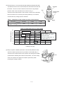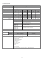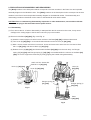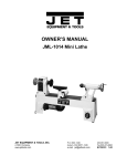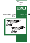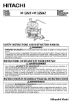
1
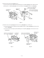
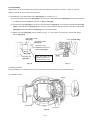
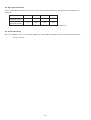
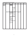
MODELS
M 12V2
M 12SA2
Hitachi
Power Tools
ROUTER
M 12V2
M 12SA2
TECHNICAL DATA
AND
SERVICE MANUAL
M
LIST Nos. M 12V2: 0669
M 12SA2: 0670
Feb. 2006
SPECIFICATIONS AND PARTS ARE SUBJECT TO CHANGE FOR IMPROVEMENT
REMARK:
Throughout this TECHNICAL DATA AND SERVICE MANUAL, a symbol(s)
is(are) used in the place of company name(s) and model name(s) of
our competitor(s). The symbol(s) utilized here is(are) as follows:
Competitor
Symbol Utilized
Company Name
3612C
C1
C2
D1
D2
Model Name
MAKITA
DEWALT
3612
DW625E
DW624
CONTENTS
Page
1. PRODUCT NAME .............................................................................................................................. 1
2. MARKETING OBJECTIVE ................................................................................................................ 1
3. APPLICATIONS ................................................................................................................................. 1
4. SELLING POINTS ............................................................................................................................. 1
4-1. Selling Point Descriptions ................................................................................................................... 2
5. SPECIFICATIONS ............................................................................................................................. 6
6. COMPARISONS WITH SIMILAR PRODUCTS ................................................................................. 7
7. PRECAUTIONS IN SALES PROMOTION ........................................................................................ 7
7-1. Handling Instructions .......................................................................................................................... 7
7-2. Name Plate ......................................................................................................................................... 8
8. REFERENCE MATTERS ................................................................................................................... 8
8-1. Collet Chuck ....................................................................................................................................... 8
9. PRECAUTIONS IN DISASSEMBLY AND REASSEMBLY ............................................................... 9
9-1. Disassembly ....................................................................................................................................... 9
9-2. Reassembly ...................................................................................................................................... 13
9-3. Insulation Tests ................................................................................................................................. 15
9-4. Cleaning the Cover ........................................................................................................................... 15
9-5. No-load Current Value ...................................................................................................................... 16
9-6. Product Accuracy .............................................................................................................................. 16
10. STANDARD REPAIR TIME (UNIT) SCHEDULES ........................................................................ 17
Assembly Diagram for M 12V2
Assembly Diagram for M 12SA2
1. PRODUCT NAME
Hitachi Router, Models M 12V2
•••••••
M 12SA2
• • • • •
Variable speed
Single speed
2. MARKETING OBJECTIVE
The new Models M 12V2 and M 12SA2 are the upgraded versions of the current Models M 12V and M 12SA
which have been sold for about 17 years from the sales start. With these new models, we reinforce our router
series. The key features of the Models M 12V2 and M 12SA2 are as follows:
(1) Variable speed dial on the handle for easy speed adjustment (Model M 12V2 only)
(2) 15-A powerful motor
(3) Quick and fine adjustment mechanism
With the new Models M 12V2 and M 12SA2, we aim to expand the share of our router series.
3. APPLICATIONS
Groove cutting, chamfering, window cutting, trimming, shaping and pattern cutting
4. SELLING POINTS
Aggressive and ergonomic design
for an enhanced look and feel
Quick and fine adjustment mechanism
Powerful motor to rout
smoothly through hardwoods
Easy-to-operate variable speed dial
on the handle (Model M 12V2)
Soft grip handle
Improved clutches
Dust guide
Improved operability by
attaching to the bench stand
Model M 12V2
--- 1 ---
4-1. Selling Point Descriptions
(1) Quick and fine adjustment mechanism
The Models M 12V2 and M 12SA2 are provided with the lever that has the quick and fine adjustment
mechanism. All conventional routers have quick adjustment mechanism and some routers have fine
adjustment mechanism by attaching the accessory. However, the routers attached with the accessory for fine
adjustment cannot be used for quick adjustment application. So the operators need to detach and attach the
accessories according to the works. Because the Models M 12V2 and M 12SA2 are equipped with the lever
that allows to switch between the quick adjustment mechanism and the fine adjustment mechanism, operators
can easily use both functions properly. How to use the quick and fine adjustment lever is exemplified below.
1
Quick adjustment mechanism (Fig. 1)
Turn the quick adjustment lever in a counterclockwise
direction until the quick adjustment lever stops with the
stopper screw.
2
Fine adjustment mechanism (Fig. 2)
Turn the quick adjustment lever in a clockwise direction
Fig. 1
until the quick adjustment lever stops with the stopper
screw.
3
How to adjust finely (Fig. 3)
Attach the knob to the fine adjustment knob and loosen
the lock lever. Turning the fine adjustment knob
counterclockwise result in shallower cut, whereas turning
it clockwise result in a deeper cut.
Fig. 2
NOTE:
If the quick adjustment lever does not stop
Knob
with the stopper screw, the bolt screw is not
properly fitted. If this occurs, slightly loosen
the lock lever and press down on the unit hard
Fine adjustment
knob
Lock lever
from the top and turn the quick adjustment
Quick adjustment
lever
lever again after properly fitting the bolt screw.
Threaded column
Fig. 3
--- 2 ---
(2) Powerful motor to rout smoothly through hardwoods (Model M 12V2)
Armature
A powerful and fast motor was developed for the Models M 12V2 and
M 12SA2. The fan is made of aluminum and it has a ring-shaped
Fan
junction at the outer circumference as shown in Fig. 4.
Ring-shaped
junction
Thanks to the unique structure, the moment of inertia of the armature
that is an element for increasing the cutting efficiency is increased
and the class-top cutting speed is obtained.
Table 1 Comparison of the moment of inertia of the armature
Moment of inertia of the
armature x 10-4 (kg•m2)
Fig. 4
M 12V2
C1/C2
D1/D2
4.64
3.62
4.54
Graph of usable feeding force vs. cutting speed
Cutting speed (m/min)
16
HITACHI M 12V2
14
Test conditions
Power source: 230 V, 50 Hz
Workpiece: MDF
Bit used: Straight bit dia. 1/2"
Cutting depth: 1/2"
12
C1/C2
10
8
6
4
D1/D2
2
0
2
2.5
3
3.5
4
4.5
5
5.5
Feeding force (kg)
(3) Easy-to-operate variable speed dial on the handle (Model M 12V2)
A dial for rotation speed control is provided on the handle (Fig. 5).
Thanks to this unique structure, the operator can change the rotation
Dial
speed without releasing the hand from the handle. So when cutting
works, the operator can adjust the rotation speed finely while
checking the cutting condition.
Fig. 5
--- 3 ---
(4) Improved operability by attaching to the bench stand
The Models M 12V2 and M 12SA2 are provided with the following functions that can lighten the burden
imposed on the operator.
(4-1) The spring can be detached from the column
The spring that assists movement of the housing is installed in the column. However, when an operator
moves a router with the bench stand attached, it is very hard to ajust the cutting depth of the bit from the
surface of the bench stand because the spring force is added to the weight of the router. The Models
M 12V2 and M 12SA2 have a structure that allows the spring to be detached from the column. When the
spring is detached first and then the router is installed to the bench stand, the load of movement of the main
body is light and it is easy to slide. Be sure to detach the spring before attaching the router to the bench
stand. How to detach the spring is exemplified below.
1
Loosen the four sub base screws and remove the sub
base.
2
Stopper bolt
Loosen the stopper bolt and remove it. Then the spring
can be removed.
NOTE:
Spring
Remove the stopper bolt with the main unit (router) fixed at its
Fig. 6
maximum height. Otherwise, the stopper bolt and the spring
may be discharged and it may cause injury to persons.
(4-2) The bit can be changed at the upper side of the bench stand
The Models M 12V2 and M 12SA2 are constructed so that the collet chuck protrudes approximately 6 mm
from the upper side of the bench stand when applying the maximum compression to the router with the
bench stand mounted. Thanks to this construction, the bit can be easily replaced at the upper side of the
bench stand. In addition, the Models M 12V2 and M 12SA2 are easier to operate by attaching to the bench
stand.
(5) Dust guide diverts cutting debris away from the operator
1
Dust guide
Match the two grooves on the base and insert the two dust guide tabs
Screw
into holes located at the base side from the top. Tighten the dust
guide with a screw. The dust guide diverts cutting debris away from
Dust guide
adapter
the operator and directs the discharge in a consistent direction.
2
By fitting the dust guide adapter into the dust guide cutting debris
discharge vent, the dust extractor can be attached.
Tab
Tab
Fig. 7
--- 4 ---
(6) Improvement of clutches
The Models M 12V2 and M 12SA2 are provided with the collet chuck that clutch the bit into the armature
shaft and is improved clutch.
Table 2 Loosening torque to tightening torque
Tightening
torque
100 kg-cm
200 kg-cm
M 12V2/M 12SA2
80 kg-cm
180 kg-cm
Model
35 kg-cm
M12
--- 5 ---
5. SPECIFICATIONS
M 12V2
Model
M 12SA2
Collet chuck capacity
12 mm and 8 mm (or 1/2" and 1/4")
Type of power source
AC single-phase 50 Hz or 60 Hz
Type of motor
AC single-phase commutator motor
Voltage and input
Voltage (V)
Current (A)
Input (W)
Voltage (V)
Current (A)
Input (W)
110
15
1,570
110
15
1,700
120
15
1,700
120
15
1,700
220
8.1
1,700
230
9.2
2,000
230
7.8
1,700
(For Australia)
240
9.6
2,200
240
7.5
1,700
(Others)
240
8.8
2,000
240
7.5
1,700
Enclosure
Head cover
Polycarbonate resin
Housing
Polycarbonate resin, elastomer
End bracket
Die-cast aluminum alloy
Base
Die-cast aluminum alloy
Handle R (A)
Polycarbonate resin
Handle L (A)
Handle R (B)
Polycarbonate resin, elastomer
Handle L (B)
Type of switch
Dustproof snap switch
Main body stroke
65 mm (2-9/16")
Speed
No-load
8,000 to 22,000/min.
22,000/min.
Full-load
8,000 to 19,000/min.
15,000/min.
13.9 lbs (6.3 kg)
13.7 lbs (6.2 kg)
Weight
Standard accessories
12 mm (or 1/2") collet chuck
8 mm (or 1/4") collet chuck
Template guide
Template guide adapter
Centering gauge
Dust guide
Dust guide adapter
Straight guide
Knob
23 mm wrench
Case (M 12V2 only except for the U.S.A., Japan and Russia)
--- 6 ---
6. COMPARISONS WITH SIMILAR PRODUCTS
Maker
HITACHI
Model name
Power
M 12V2, M 12SA2
Europe
C1/C2
D1/D2
(A)
2,000 (1,700)
1,850/1,650
2,000/1,600
(HP)
3-1/4
3-1/4
3
(/min.)
8,000 to 22,000
(22,000)
9,000 to 23,000
/22,000
8,000 to 20,000
/22,000
No-load noise level
(dB)
83.5
80.0
86.6
Collet chuck capacity
(mm)
12 (1/2"), 8 (1/4")
12 (1/2")
12 (1/2")
Main body stroke
(mm)
65
60
62
Weight
(kg)
6.3 (6.2)
6.0 (5.8)
5.1 (5.1)
mm
mm
180 (7-3/32")
70 (2-3/4")
170 (6-11/16")
160.5 (6-5/16")
59 (2-5/16")
Provided
None
Provided
Handle
Top cover
Top cover
USA
No-load speed
Base configuration
D
H
Quick and fine adjustment
Position of dial
7. PRECAUTIONS IN SALES PROMOTION
In the interest of promoting the safest and most efficient use of the Models M 12V2 and M 12SA2 Routers by all
of our customers, it is very important that at the time of sale the salesperson carefully ensures that the buyer
seriously recognizes the importance of the contents of the Handling Instructions, and fully understands the
meaning of the precautions listed on the Caution Plate attached to each tool.
7-1. Handling Instructions
Although every effort is made in each step of design, manufacture and inspection to provide protection against
safety hazards, the dangers inherent in the use of any electric power tool cannot be completely eliminated.
Accordingly, general precautions and suggestions for the use of electric power tools, and specific precautions
and suggestions for the use of the router is listed in the Handling Instructions to enhance the safe, efficient use of
the tool by the customer. Salespersons must be thoroughly familiar with the contents of the Handling Instructions
to be able to offer appropriate guidance to the customer during sales promotion.
--- 7 ---
7-2. Name Plate
Each tool is provided with a Name Plate which lists the following basic safety precautions in the use of the tool.
(1) For the U.S.A. and Canada
(2) For Australia, New Zealand, Asia and South Africa
8. REFERENCE MATTERS
8-1. Collet Chuck
The collet chuck portion consists of a collet chuck and a collet nut. The collet chuck and the nut are assembled as
a single unit to maintain desired dimensional accuracy. Therefore, when replacing the collet chuck portion, be
sure to replace it entirely.
--- 8 ---
9. PRECAUTIONS IN DISASSEMBLY AND REASSEMBLY
The [Bold] numbers in the descriptions below correspond to the item numbers in the Parts Lists and exploded
assembly diagram for the Model M 12V2. The ([Bold]) numbers in the descriptions below correspond to the item
numbers in the Parts Lists and exploded assembly diagram for the Model M 12SA2. The disassembly and
reassembly procedures described are the same for the Models M 12V2 and M 12SA2.
CAUTION: Prior to commencing disassembly, inspection or other maintenance, ensure without fail that
the plug is disconnected from the power source.
9-1. Disassembly
(1) First, remove the bit. If further disassembly is attempted with the bit mounted on the router, it may cause
damage to the cutting edges of the bit and/or serious injury to the handler.
(2) Removal of the Base [89] ([85]) (Fig. 8 and Fig. 9)
(a) Stand the router upright so that the bottom surface of the Base [89] ([85]) is directed downward.
(b) Turn Lever (B) [58] ([56]) in a counterclockwise direction and lock Lever (A) [62] ([60]).
(c) With a 10-mm wrench and a hex. bar wrench, loosen and remove the Seal Lock Hex. Socket Hd. Bolt
M5 x 14 [45] ([43]), and remove Knob (C) [46] ([44]).
(d) Release Lever (A) [62] ([60]) and disassemble the Base [89] ([85]) from the main body. As Plunger
Spring (R) [41] ([39]) and Plunger Spring (L) [48] ([46]) are installed within the columns of the Base [89]
([85]), be sure to support the main body by firmly gripping the handle during disassembly.
Seal Lock Hex. Socket Hd.
Bolt M5 x 14 [45] ([43])
Knob (C) [46] ([44])
Lever (A)
[62] ([60])
Lever (B) [58] ([56])
Plunger Spring (R)
[41] ([39])
Plunger Spring (L)
[48] ([46])
Fig. 8
Base
[89] ([85])
Fig. 9
--- 9 ---
(3) Removal of the Head Cover [3] ([3]) (Fig. 10)
Loosen and remove the two Tapping Screws (W/Flange) D4 x 30 (Black) [2] ([2]) and two Tapping Screws
(W/Flange) D4 x 16 (Black) [21] ([19]), and move the Head Cover [3] ([3]) toward the Cord [36] ([34]).
Tapping Screw (W/Flange)
D4 x 30 (Black) [2] ([2])
Head Cover
[3] ([3])
Housing Ass'y
[23] ([21])
Tapping Screw (W/Flange)
D4 x 16 (Black) [21] ([19])
Cord
[36] ([34])
Fig. 10
(4) Remove Front Cover (B) [19] ([17]) and Front Cover (C) [52] ([50]) (Fig. 11 and Fig. 12)
(a) Loosen and remove the two Machine Screws (W/Washers) M4 x 12 (Black) [44] ([42]), and remove Front
Cover (C) [52] ([50]).
(b) Loosen and remove the Tapping Screw (W/Flange) D4 x 20 (Black) [18] ([16]), and remove Front Cover
(B) [19] ([17]).
Machine Screw (W/Washers)
M4 x 12 (Black) [44] ([42])
End Bracket
[53] ([51])
Tapping Screw (W/Flange)
D4 x 20 (Black) [18] ([16])
Front Cover (C)
[52] ([50])
Front Cover (B)
[19] ([17])
Fig. 11
Fig. 12
--- 10 ---
Housing Ass'y
[23] ([21])
(5) Remove the Armature [28] ([26]) and the End Bracket [53] ([51]) (Fig. 13)
(a) Remove the Carbon Brushes (1 Pair) [33] ([31]).
(b) Loosen and remove the two Tapping Screws (W/Flange) D4 x 16 (Black) [21] ([19]) and the Machine
Screw (W/Washers) M6 x 30 (Black) [37] ([35]), and remove Handle (R) B [67] ([64]).
(c) Disconnect Cord (A) [66] from the Controller Circuit Dial Set [5] and remove Handle (R) A [64]
(Model M 12V2 only).
(d) Loosen and remove the four Tapping Screws D5 x 50 [68] ([65]).
(e) Being very careful to avoid hitting the Magnet [6] against the stator ass'y, remove the Armature [28] ([26])
and the End Bracket [53] ([51]) from the Housing Ass'y [23] ([21]). As the Magnet [6] is very fragile, it
must be handled with the utmost caution (Model M 12V2 only).
(f) Take out the Lock Piece [60] ([58]) which is mounted in the End Bracket [53] ([51]).
(g) Being very careful not to damage the magnet component, fit a 14-mm wrench onto the hexagonal portion
of the Magnet [6], and loosen and remove it from the Armature [28] ([26]) (Model M 12V2 only).
(h) Loosen and remove the three Machine Screws (W/Washers) M4 x 12 (Black) [44] ([42]), then remove the
Bearing Cover [71] ([68]), Pushing Button [73] ([70]) and Lock Spring (A) [72] ([69]).
(i) Being very careful not to damage the outer surface of its core, secure the Armature [28] ([26]) in a vise.
(j) Turn the Thrust Nut [70] ([67]) counterclockwise with a wrench to loosen and remove it.
(k) With a handle press, disassemble the Armature [28] ([26]) from the End Bracket [53] ([51]).
Housing Ass'y
[23] ([21])
Carbon Brush
(1 Pair) [33] ([31])
End Bracket
[53] ([51])
Handle (R) A
[64] ([62])
Machine Screw
(W/Washers) M6 x 30
(Black) [37] ([35])
Handle (R) B
[67] ([64])
Dial set
Magnet [6]
Armature
[28] ([26])
Thrust Nut
[70] ([67])
Bearing Cover
[71] ([68])
Lock Spring (A)
[72] ([69])
Pushing Button
[73] ([70])
Machine Screw (W/Washers)
M4 x 12 (Black) [44] ([42])
Tapping Screw
(W/Flange) D4 x 16
(Black) [21] ([19])
Cord (A) [66]
Tapping Screw
D5 x 50 [68] ([65])
Fig. 13
--- 11 ---
(6) Remove the Stator Ass'y [26] ([24]) (Fig. 14)
(a) Remove the Controller Circuit Dial Set [5]. (Model M 12V2 only)
(b) Loosen and remove the two Tapping Screws D4 x 12 [7] ([5]), and remove the Bearing Bushing [8] ([6]).
(c) Disconnect the Brush Terminals [25] ([23]) of the Stator Ass'y [26] ([24]) from the brush holders.
(d) Lift out the Switch (2P Pillar Type) W/O Lock [30] ([28]) from the Housing Ass'y [23] ([21]).
(e) Loosen the minus-head screws on the terminals of the Switch (2P Pillar Type) W/O Lock [30] ([28]), and
disconnect the lead wires of the Stator Ass'y [26] ([24]) from the Switch (2P Pillar Type) W/O Lock [30] ([28]).
(f) Loosen and remove the two Hex. Hd. Tapping Screws D5 x 70 [27] ([25]).
(g) With a plastic hammer, gently tap on the lower end of the Housing Ass'y [23] ([21]) (the end where the End
Bracket [53] ([51]) is connected) to loosen and separate the Stator Ass'y [26] ([24]) from the Housing Ass'y
[23] ([21]).
Switch (2P Pillar Type)
W/O Lock [30] [(28)]
Controller Circuit
Dial Set [5]
Brush Terminal
[25] [(23)]
Tapping Screw
D4 x 12 [7] [(5)]
Bearing Bushing
[8] [(6)]
Stator Ass'y
[26] [(24)]
Housing Ass'y
[23] [(21)]
Hex. Hd. Tapping Screw
D5 x 70 [27] [(25)]
Fig. 14
(7) CAUTION:
As these models are specifically designed to ensure that the armature is dynamically balanced, there
is extremely little allowable play or imbalance in comparison with other Hitachi electric power tools.
For this reason, be sure to handle the armature and its associated parts very carefully during
disassembly and reassembly.
(8) Remove the Special Nut TR12 [55] ([53]) (Fig. 15)
(a) Loosen the Hex. Socket Set Screw M6 x 6 [59] ([57]) and remove Lever (B) [58] ([56]).
(b) Turn the Special Bolt M20 [56] ([54]) clockwise and remove it.
(c) Loosen and remove the Machine Screw (W/Washers) M4 x 12 (Black) [44] ([42]), and remove the Special
Nut TR12 [55] ([53]) from the Special Bolt M20 [56] ([54]).
Lever (B) [58] [(56)]
End Bracket [53] [(51)]
Hex. Socket Set Screw
M6 x 6 [59] [(57)]
Machine Screw (W/Washers)
M4 x 12 (Black) [44] [(42)]
Special Bolt M20
[56] [(54)]
Special Nut TR12 [55] [(53)]
Fig. 15
--- 12 ---
9-2. Reassembly
Reassembly can be accomplished by following the disassembly procedures in reverse. However, special
attention should be given to the following items.
(1) Reassembly of the Special Nut TR12 [55] ([53]) (Fig. 16 and Fig. 17)
(a) Insert the Special Nut TR12 [55] ([53]) to the hole of the Special Bolt M20 [56] ([54]) and secure them with
the Machine Screw (W/Washers) M4 x 12 (Black) [44] ([42]).
(b) Insert the Spring [54] ([52]) to the hole of the End Bracket [53] ([51]), and insert the Special Bolt M20 [56]
([54]) to the End Bracket [53] ([51]) with turning counterclockwise until the surface of the Special Bolt M20
[56] ([54]) and the End Bracket [53] ([51]) becomes equal height.
(c) Attach Lever (B) [58] ([56]) with the position as Fig. 17. And secure it with the Hex. Socket Set Screw
M6 x 6 [59] ([57]).
Special Nut TR12
[55] ([53])
Special Nut M20
[56] ([54])
Lever (B) [58] ([56])
Machine Screw
(W/Washers) M4 x 12
(Black) [44] ([42])
Spring
[54] ([52])
End Bracket
[53] ([51])
Make the surface of the
special bolt M20 and
the end bracket even.
Fig. 16
Fig. 17
(2) Wiring procedure
During installation, be careful not to pinch the lead wires between the housing and the head cover.
(2-1) Model M 12V2
Switch
Controller
Connector
Fig. 18
--- 13 ---
(2-2) Model M 12SA2
Switch
Noise suppressor
Fig. 19
(3) Wiring diagram
(3-1) Model M 12V2
Switch
Stator
Armature
Control circuit
ass'y
A
Power source
Stator
Dial ass'y
Fig. 20
(3-2) Model M 12SA2
Switch
Stator
Noise
suppressor
Armature
Power source
Stator
Fig. 21
--- 14 ---
(4) Tightening torque of screws and bolts
Tapping screw D4 x 12
2.0
0.5 N•m (20
5 kgf•cm)
Tapping screw D4 x 16
2.0
0.5 N•m (20
5 kgf•cm)
Tapping screw D4 x 20
2.0
0.5 N•m (20
5 kgf•cm)
Tapping screw D4 x 30
2.0
0.5 N•m (20
5 kgf•cm)
Tapping screw D5 x 50
2.9
0.5 N•m (30
5 kgf•cm)
Hex. hd. tapping screws D5 x 70
2.9
0.5 N•m (30
5 kgf•cm)
Machine screw M4 x 8
1.8
0.4 N•m (18
4 kgf•cm)
Machine screw M4 x 12
1.8
0.4 N•m (18
4 kgf•cm)
Machine screw M5 x 6
3.4
0.7 N•m (35
7 kgf•cm)
Machine screw M6 x 10
4.9
1.0 N•m (50
10 kgf•cm)
Machine screw M6 x 30
4.9
1.0 N•m (50
10 kgf•cm)
Flat screw M5 x 14
3.4
0.7 N•m (35
7 kgf•cm)
Hex. socket set screw M5 x 8
0.75
Hex. socket set screw M6 x 6
5.9
1.5 N•m (60
15 kgf•cm)
Bolt M5 x 14
3.4
0.7 N•m (35
7 kgf•cm)
Nut M5
3.4
0.7 N•m (35
7 kgf•cm)
Nut M8
9.8
2.0 N•m (100
Stopper bolt
4.9
1.0 N•m (50
0.25 N•m (7
2.5 kgf•cm)
20 kgf•cm)
10 kgf•cm)
9-3. Insulation Tests
On completion of disassembly and repair, measure the insulation resistance and conduct the insulation tests
(dielectric strength test).
Insulation resistance: 7 M Ω or more with DC 500 V megohm tester
Dielectric strength:
AC 4,000 V/1 minute,
with no abnormalities 220 V --- 240 V (and 110 V for U.K. products)
AC 2,500 V/1 minute,
with no abnormalities 100 V --- 127 V (except U.K. products)
9-4. Cleaning the Cover
Clean the exterior of the tool with a soft cloth moistened with soapy water, and dry thoroughly.
--- 15 ---
9-5. No-load Current Value
After no-load operation for 30 minutes, the no-load current value should be as specified below at a frequency of
50/60 Hz.
Voltage (V)
Current (A) max.
(Model M 12V2)
Current (A) max.
(Model M 12SA2)
110
120
230
240
7.5
7.0
4.5
4.5
5.5
6.0
3.8
3.6
Note: For the Model M 12V2, check the no-load current value by setting the dial to "6".
9-6. Product Accuracy
Bit run out: With a 12 mm or 1/2" test bar applied, run out should be less than 0.4 mm at a 100 mm distance from
the top of chuck.
--- 16 ---
10. STANDARD REPAIR TIME (UNIT) SCHEDULES
MODEL
Variable
Fixed
M 12V2
10
20
30
40
Work Flow
M 12SA2
Switch
Controller Circuit
(A) Dial Set
Cord
Cord Armor
Cord Holder
Cord (A)
General Assembly
Head Cover
Armature Ass'y
Rubber Ring
Collet Chuck
Bearing Bushing
Front Cover (B) Ball Bearing
6200VV
Marker
Ball
Bearing
Pole Holder
6004VV
Bearing Cover
Magnet
Handle (L) A
Handle (R) A
Handle (L) B
Handle (R) B
End Bracket
Sub Base (A)
Template
Guide Adapter
Stopper Block
Dust Guide
Base
Lever (B)
Lever (A)
--- 17 ---
Housing Ass'y
Stator Ass'y
50
60 min.
Hitachi Power Tools
LIST NO. 0669
ELECTRIC TOOL PARTS LIST
ROUTER
Model M 12V2
2006
2 • 22
•
(E1)
40
1
40
35
2
42
41
21
48
3
43
36
45
4
44
37
46
58
21
5
56
39
55
12
62
16
14
61
60
17
8
63
54
11
7
57
47
13
6
59
44
38
15
14
9
34
30
33
31
10
64
32
5
66
23
53
67
52
22
44
21
20
69
49
70
19
18
68
71
72
44
73
21
37
74
25
24
97
26
97
75
29
75
27
76
44
78
79
77
28
95
83
96
84
501
502
85
80
81
503
504
82
89
86
81
87
91
77
92
88
93
505
508
509
87
510
506
507
511
94
93
90
PARTS
ITEM
NO.
1
M 12V2
NO.
USED
CODE NO.
DESCRIPTION
HITACHI LABEL (B)
1
2
305-490
TAPPING SCREW (W/FLANGE) D4X30 (BLACK)
2
3
325-168
HEAD COVER
1
HITACHI LABEL (A)
1
4
REMARKS
*
5
325-200
CONTROLLER CIRCUIT (C) DIAL SET 100-120V
1
*
5
325-368
CONTROLLER CIRCUIT (A) DIAL SET 230V
1
*
5
325-218
CONTROLLER CIRCUIT (A) DIAL SET 230-240V
1 FOR SIN, KUW, NZL, AUS, SAF
6
301-797
MAGNET
1
7
954-017
TAPPING SCREW D4X12
2
8
325-169
BEARING BUSHING
1
9
325-184
RUBBER RING
1
10
620-0VV
BALL BEARING 6200VVCMPS2L
1
11
959-141
CONNECTOR 50092 (10 PCS.)
1
12
961-820
TUBE (D)
1
*
13
953-327
CORD ARMOR D8.8
1
*
13
938-051
CORD ARMOR D10.1
1
14
984-750
TAPPING SCREW (W/FLANGE) D4X16
4
15
937-631
CORD CLIP
1
*
16
981-373
TUBE (D)
2
*
16
961-820
TUBE (D)
2 FOR USA, CAN
17
325-203
CORD HOLDER
1
18
302-086
TAPPING SCREW (W/FLANGE) D4X20 (BLACK)
1
19
325-170
FRONT COVER (B)
1
20
325-198
MARKER
1
21
305-812
TAPPING SCREW (W/FLANGE) D4X16 (BLACK) 10
22
325-197
POLE HOLDER
1
23
325-219
HOUSING ASS’Y
1 INCLUD. 31, 32
24
325-196
STOPPER POLE (A)
1
25
958-032
BRUSH TERMINAL
2
*
26
340-659C STATOR ASS’Y 120V
1 INCLUD. 25
*
26
340-659G STATOR ASS’Y 230V
1 INCLUD. 25
*
26
340-659E STATOR ASS’Y 230V
1 INCLUD. 25 FOR SIN, SAF
*
26
340-659F STATOR ASS’Y 240V
1 INCLUD. 25
*
26
340-659H STATOR ASS’Y 240V
1 INCLUD. 25 FOR AUS
27
961-400
2
*
28
360-748U ARMATURE ASS’Y 110V-120V
1 INCLUD. 10, 69
*
28
360-748E ARMATURE 230V-240V
1
29
325-960
LEVER
1
30
301-821
SWITCH (2P PILLAR TYPE) W/O LOCK
1
31
938-477
HEX. SOCKET SET SCREW M5X8
2
32
980-487
BRUSH HOLDER
2
33
999-044
CARBON BRUSH (1 PAIR)
2
34
940-540
BRUSH CAP
2
NAME PLATE
1
35
HEX. HD. TAPPING SCREW D5X70
*
36
500-234Z CORD
1 (CORD ARMOR D8.8)
*
36
500-247Z CORD
1 (CORD ARMOR D10.1) FOR FIN, NOR, SWE, DEN, AUT
*
36
500-423Z CORD
1 (CORD ARMOR D8.8) FOR SIN, KUW
*
36
500-439Z CORD
1 (CORD ARMOR D8.8) FOR NZL, AUS
*
36
500-242Z CORD
1 (CORD ARMOR D10.1) FOR USA, CAN
*
36
500-248Z CORD
1 (CORD ARMOR D10.1) FOR SUI
*
36
500-435Z CORD
1 (CORD ARMOR D8.8) FOR GBR (230V)
--- 2 ---
* ALTERNATIVE PARTS
2 -- 06
PARTS
ITEM
NO.
* 36
M 12V2
CODE NO.
NO.
USED
DESCRIPTION
REMARKS
500-396Z CORD
1 (CORD ARMOR D10.1) FOR GBR (110V)
37
307-443
MACHINE SCREW (W/WASHERS) M6X30 (BLACK)
2
38
325-220
HANDLE (L) B
1
39
325-171
HANDLE (L) A
1
40
325-180
SPRING GUIDE
2
41
325-177
PLUNGE SPRING (R)
1
42
325-214
KNOB (B) ASS’Y
1 INCLUD. 43
43
872-654
O-RING (1AP-10)
2
44
935-196
MACHINE SCREW (W/WASHERS) M4X12 (BLACK)
8
45
984-509
SEAL LOCK HEX. SOCKET HD. BOLT M5X14
1
46
325-194
KNOB (C)
1
47
325-195
GUIDE SLEEVE
1
48
325-176
PLUNGE SPRING (L)
1
49
301-801
WING BOLT M6X27
1
52
325-173
FRONT COVER (C)
1
*
53
325-205
END BRACKET
1
*
53
326-043
END BRACKET
1 FOR USA, CAN
54
325-193
SPRING
1
55
325-192
SPECIAL NUT TR12
1
56
325-191
SPECIAL BOLT M20
1
57
949-811
HEX. SOCKET HD. BOLT M4X8 (10 PCS.)
1
58
325-190
LEVER (B)
1
59
985-033
HEX. SOCKET SET SCREW M6X6
1
60
971-848
LOCK PIECE
1
61
325-187
LOCK SCREW M10
1
*
62
326-042
LEVER (A)
1
*
62
322-601
LEVER (A) W/O STOPPER
1 FOR SIN, KUW, SAF, USA, CAN
63
997-314
MACHINE SCREW (W/WASHERS) M6X10
1
64
325-172
HANDLE (R) A
1
66
325-202
CORD (A)
1
67
325-962
HANDLE (R) B
1
68
307-100
TAPPING SCREW D5X50
4
69
600-4VV
BALL BEARING 6004VVCMPS2L
1
70
325-186
THRUST NUT
1
71
325-185
BEARING COVER
1
72
325-183
LOCK SPRING (A)
1
73
325-182
PUSHING BUTTON
1
*
74
325-199
COLLET CHUCK 12MM
1
*
74
323-421
COLLET CHUCK 1/2"
1 FOR NZL, AUS, GBR, SAF, USA, CAN
75
325-207
BELLOWS (A)
2
76
325-189
SPECIAL BOLT TR12
1
77
325-188
WASHER
2
78
325-210
DUST GUIDE
1
79
325-215
DUST GUIDE ADAPTER
1
80
949-662
HEX. SOCKET HD. BOLT M5X25 (10 PCS.)
1
81
302-012
NUT M5 (BLACK)
2
82
325-181
STOPPER BLOCK
1
83
317-200
MACHINE SCREW (W/WASHERS) M4X8 (BLACK)
1
84
962-569
WASHER (B)
1
85
971-858
SPRING (A)
1
86
949-765
HEX. SOCKET HD. BOLT M5X12 (10 PCS.)
1
2 -- 06
* ALTERNATIVE PARTS
--- 3 ---
PARTS
ITEM
NO.
87
M 12V2
CODE NO.
NO.
USED
DESCRIPTION
325-178
STOPPER BOLT
2
REMARKS
88
949-558
NUT M8 (10 PCS.)
1
*
89
325-342
BASE
1
*
89
325-206
BASE
1 FOR USA, CAN
90
325-179
SUB BASE
1
91
992-013
SEAL LOCK FLAT HD. SCREW M5X14
4
92
325-211
TEMPLATE GUIDE ADAPTER
1
93
949-234
MACHINE SCREW M5X6 (10 PCS.)
4
94
956-790
TEMPLATE GUIDE D18
1
95
301-806
WING BOLT M6X15
2
96
947-859
LOCK SPRING
2
97
323-426
FELT
2 FOR USA, CAN
*
--- 4 ---
* ALTERNATIVE PARTS
2 -- 06
STANDARD ACCESSORIES
ITEM
NO.
501
502
CODE NO.
M 12V2
NO.
USED
DESCRIPTION
956-797
STRAIGHT GUIDE
1
325-216
GUIDE BAR (A)
2
REMARKS
503
301-806
WING BOLT M6X15
2
504
323-295
WRENCH 23MM
1
*
505
325-212
COLLET CHUCK 8MM
1
*
505
323-293
COLLET CHUCK 1/4"
1
*
506
325-213
CENTERING GAUGE
1
*
506
325-223
CENTERING GAUGE
1
FOR NZL, AUS, GBR, SAF, USA, CAN
*
507
325-222
CASE
1
EXCEPT FOR USA, CAN, RUS
508
325-217
BAR HOLDER
1
509
949-394
WING BOLT M6X10 (10 PCS.)
1
*
510
956-793
FEED SCREW
1
511
325-224
TEMPLATE GUIDE ADAPTER
1
FOR NZL, AUS, GBR, SAF, USA, CAN
FOR USA, CAN
OPTIONAL ACCESSORIES
ITEM
NO.
* 601
CODE NO.
NO.
USED
DESCRIPTION
REMARKS
313-765
STRAIGHT BIT (TCT) D1/2"X1/2"
1
FOR NZL, AUS, GBR, SAF, USA, CAN
EXCEPT FOR NZL, AUS, GBR, SAF, USA, CAN
*
602
307-801
COLLET CHUCK 1/2"
1
*
603
323-293
COLLET CHUCK 1/4"
1
EXCEPT FOR NZL, AUS, GBR, SAF, USA, CAN
*
604
325-369
TEMPLATE GUIDE ADAPTER
1
FOR NZL, AUS, GBR, SAF
*
605
323-298
TEMPLATE GUIDE D7.9
1
FOR USA,CAN
*
606
323-299
TEMPLATE GUIDE D9.5
1
FOR USA,CAN
*
607
323-300
TEMPLATE GUIDE D11.1
1
FOR USA,CAN
*
608
323-301
TEMPLATE GUIDE D12.7
1
FOR USA,CAN
*
609
323-302
TEMPLATE GUIDE D15.9
1
FOR USA,CAN
*
610
323-303
TEMPLATE GUIDE D19.1
1
FOR USA,CAN
*
611
323-304
TEMPLATE GUIDE D20.2
1
FOR USA,CAN
*
612
323-305
LOCK NUT
1
FOR USA,CAN
613
956-794
TRIMMER GUIDE
1
614
956-803
DOUBLE FLUSH TRIMMING BIT (TCT) D12X12
1
615
956-802
DOUBLE FLUSH TRIMMING BIT (TCT) D8X8
1
616
956-801
DOUBLE FLUSH TRIMMING BIT (TCT) D6X6
1
617
956-806
FLUSH TRIMMING BIT (TCT) D12X12
1
618
956-805
FLUSH TRIMMING BIT (TCT) D8X8
1
619
956-804
FLUSH TRIMMING BIT (TCT) D6X6
1
620
956-810
STRAIGHT BIT (TCT) D12X12
1
621
956-809
STRAIGHT BIT (TCT) D12X10
1
622
312-273
STRAIGHT BIT (TCT) D6X6
1
623
956-813
ROUND OVER BIT (TCT) D12XR8X24
1
624
956-812
ROUND OVER BIT (TCT) D12XR6X20
1
625
956-811
ROUND OVER BIT (TCT) D12XR4.5X19
1
626
956-814
CHAMFERING BIT (TCT) 45û D6X20
1
627
956-816
DOVETAIL BIT (TCT) D8X15
1
628
956-815
DOVETAIL BIT (TCT) D6X12
1
629
956-928Z CHUCK SLEEVE 1/2"X3/8"
1
630
956-931Z CHUCK SLEEVE 1/2"X10"
1
631
956-759
1
2 -- 06
CHUCK SLEEVE 1/2"X8"
* ALTERNATIVE PARTS
--- 5 ---
OPTIONAL ACCESSORIES
ITEM
NO.
632
CODE NO.
DESCRIPTION
M 12V2
NO.
USED
303-347
TEMPLATE GUIDE D9.5
1
633
303-348
TEMPLATE GUIDE D10
1
634
303-349
TEMPLATE GUIDE D11.1
1
635
303-350
TEMPLATE GUIDE D12
1
636
303-351
TEMPLATE GUIDE D12.7
1
637
303-352
TEMPLATE GUIDE D14
1
638
303-353
TEMPLATE GUIDE D16
1
639
956-932
TEMPLATE GUIDE D20
1
640
303-354
TEMPLATE GUIDE D24
1
641
956-933
TEMPLATE GUIDE D27
1
642
956-934
TEMPLATE GUIDE D30
1
643
303-355
TEMPLATE GUIDE D40
1
--- 6 ---
* ALTERNATIVE PARTS
REMARKS
Printed in Japan
(060222N)
2 -- 06
Hitachi Power Tools
LIST NO. 0670
ELECTRIC TOOL PARTS LIST
ROUTER
Model M 12SA2
2006
2 • 22
•
(E1)
38
1
38
33
2
40
39
19
46
3
41
34
43
4
42
35
44
56
19
55
45
9
54
37
5
6
7
10
8
12
10
14
11
15
57
42
36
53
61
52
60
59
58
32
28
31
29
62
30
13
63
21
64
51
50
20
42
19
18
66
47
67
17
16
65
68
69
42
35
19
70
71
23
22
93
24
93
27
25
72
42
74
75
73
26
91
79
92
80
501
81
502
76
77
503
85
82
77
83
504
78
87
73
88
84
89
83
505
506
507
508
509
510
90
89
86
PARTS
ITEM
NO.
1
CODE NO.
DESCRIPTION
HITACHI LABEL (B)
1
2
305-490
TAPPING SCREW (W/FLANGE) D4X30 (BLACK)
2
3
325-168
HEAD COVER
1
HITACHI LABEL (A)
1
4
*
*
M 12SA2
NO.
USED
5
954-017
TAPPING SCREW D4X12
2
6
325-226
BEARING BUSHING
1
7
325-184
RUBBER RING
1
8
620-0VV
BALL BEARING 6200VVCMPS2L
1
9
953-327
CORD ARMOR D8.8
1
9
938-051
CORD ARMOR D10.1
1
10
984-750
TAPPING SCREW (W/FLANGE) D4X16
4
REMARKS
11
937-631
CORD CLIP
1
*
12
961-820
TUBE (D)
2 EXCEPT FOR USA, CAN, KUW, SIN, INA, THA, KOR
*
13
930-039
NOISE SUPPRESSOR
1 EXCEPT FOR USA, CAN, KUW, SIN, INA, THA, KOR
*
14
981-373
TUBE (D)
2
*
14
961-820
TUBE (D)
2 FOR USA, CAN
15
325-203
CORD HOLDER
1
16
302-086
TAPPING SCREW (W/FLANGE) D4X20 (BLACK)
1
17
325-170
FRONT COVER (B)
1
18
325-198
MARKER
1
19
305-812
TAPPING SCREW (W/FLANGE) D4X16 (BLACK) 10
20
325-197
POLE HOLDER
1
21
325-219
HOUSING ASS’Y
1 INCLUD. 29, 30
22
325-196
STOPPER POLE (A)
1
BRUSH TERMINAL
2
23
958-032
*
24
340-668C STATOR ASS’Y 110V-120V
1 INCLUD. 23
*
24
340-668E STATOR ASS’Y 220V-230V
1 INCLUD. 23 FOR THA, INA, SIN, KOR
*
24
340-668G STATOR ASS’Y 230V
1 INCLUD. 23
*
24
340-668H STATOR ASS’Y 240V
1 INCLUD. 23
*
24
340-668F STATOR ASS’Y 240V
1 INCLUD. 23 FOR KUW
25
961-400
2
*
26
360-750U ARMATURE ASS’Y 110V-120V
1 INCLUD. 8, 66
*
26
360-750E ARMATURE 220V-230V
1
*
26
360-750F ARMATURE 240V
1
27
325-960
LEVER
1
28
301-821
SWITCH (2P PILLAR TYPE) W/O LOCK
1
29
938-477
HEX. SOCKET SET SCREW M5X8
2
30
980-487
BRUSH HOLDER
2
31
999-044
CARBON BRUSH (1 PAIR)
2
32
940-540
BRUSH CAP
2
33
*
HEX. HD. TAPPING SCREW D5X70
34
NAME PLATE
500-234Z CORD
1
1 (CORD ARMOR D8.8)
*
34
500-247Z CORD
1 (CORD ARMOR D10.1) FOR AUT, FIN, DEN, SWE, NOR
*
34
500-461Z CORD
1 (CORD ARMOR D10.1) FOR GBR (110V)
*
34
500-435Z CORD
1 (CORD ARMOR D8.8) FOR GBR (230V)
*
34
500-248Z CORD
1 (CORD ARMOR D10.1) FOR SUI
*
34
500-242Z CORD
1 (CORD ARMOR D10.1) FOR USA, CAN
*
34
500-439Z CORD
1 (CORD ARMOR D8.8) FOR AUS, NZL
*
34
500-423Z CORD
1 (CORD ARMOR D8.8) FOR KUW, SIN
*
34
500-455Z CORD
1 (CORD ARMOR D10.1) FOR THA
*
34
500-234Z CORD
1 (CORD ARMOR D8.8) FOR KOR
--- 2 ---
* ALTERNATIVE PARTS
2 -- 06
PARTS
ITEM
NO.
35
M 12SA2
CODE NO.
NO.
USED
DESCRIPTION
307-443
MACHINE SCREW (W/WASHERS) M6X30 (BLACK)
2
36
325-220
HANDLE (L) B
1
37
325-171
HANDLE (L) A
1
38
325-180
SPRING GUIDE
2
39
325-177
PLUNGE SPRING (R)
1
40
325-214
KNOB (B) ASS’Y
1
41
872-654
O-RING (1AP-10)
2
42
935-196
MACHINE SCREW (W/WASHERS) M4X12 (BLACK)
8
43
984-509
SEAL LOCK HEX. SOCKET HD. BOLT M5X14
1
44
325-194
KNOB (C)
1
45
325-195
GUIDE SLEEVE
1
46
325-176
PLUNGE SPRING (L)
1
47
301-801
WING BOLT M6X27
1
50
325-173
FRONT COVER (C)
1
51
325-228
END BRACKET
1
52
325-193
SPRING
1
53
325-192
SPECIAL NUT TR12
1
54
325-191
SPECIAL BOLT M20
1
55
949-811
HEX. SOCKET HD. BOLT M4X8 (10 PCS.)
1
56
325-190
LEVER (B)
1
57
985-033
HEX. SOCKET SET SCREW M6X6
1
58
971-848
LOCK PIECE
1
59
325-187
LOCK SCREW M10
1
*
60
326-042
LEVER (A)
1
*
60
322-601
LEVER (A) W/O STOPPER
1
61
997-314
MACHINE SCREW (W/WASHERS) M6X10
1
62
325-172
HANDLE (R) A
1
63
325-227
DIAL COVER
1
64
325-221
HANDLE (R) B
1
65
307-100
TAPPING SCREW D5X50
4
66
600-4VV
BALL BEARING 6004VVCMPS2L
1
67
325-186
THRUST NUT
1
68
325-185
BEARING COVER
1
69
325-183
LOCK SPRING (A)
1
70
325-182
PUSHING BUTTON
1
*
71
325-199
COLLET CHUCK 12MM
1
*
71
323-421
COLLET CHUCK 1/2”
1
72
325-189
SPECIAL BOLT TR12
1
73
325-188
WASHER
2
74
325-210
DUST GUIDE
1
75
325-215
DUST GUIDE ADAPTER
1
76
949-662
HEX. SOCKET HD. BOLT M5X25 (10 PCS.)
1
77
302-012
NUT M5 (BLACK)
2
78
325-181
STOPPER BLOCK
1
79
317-200
MACHINE SCREW (W/WASHERS) M4X8 (BLACK)
1
80
962-569
WASHER (B)
1
81
971-858
SPRING (A)
1
82
949-765
HEX. SOCKET HD. BOLT M5X12 (10 PCS.)
1
83
325-178
STOPPER BOLT
2
84
949-558
NUT M8 (10 PCS.)
1
85
325-206
BASE
1
2 -- 06
REMARKS
INCLUD. 41
FOR USA, CAN, THA, KUW, INA, SIN, KOR
FOR GBR, USA, CAN, AUS, NZL
* ALTERNATIVE PARTS
--- 3 ---
PARTS
ITEM
NO.
86
M 12SA2
CODE NO.
NO.
USED
DESCRIPTION
325-179
SUB BASE
1
87
992-013
SEAL LOCK FLAT HD. SCREW M5X14
4
88
325-211
TEMPLATE GUIDE ADAPTER
1
89
949-234
MACHINE SCREW M5X6 (10 PCS.)
4
90
956-790
TEMPLATE GUIDE D18
1
91
301-806
WING BOLT M6X15
2
92
947-859
LOCK SPRING
2
93
323-426
FELT
2
--- 4 ---
* ALTERNATIVE PARTS
REMARKS
2 -- 06
STANDARD ACCESSORIES
ITEM
NO.
501
502
CODE NO.
M 12SA2
NO.
USED
DESCRIPTION
956-797
STRAIGHT GUIDE
1
325-216
GUIDE BAR (A)
2
REMARKS
503
301-806
WING BOLT M6X15
2
504
323-295
WRENCH 23MM
1
*
505
325-212
COLLET CHUCK 8MM
1
*
505
323-293
COLLET CHUCK 1/4”
1
*
506
325-213
CENTERING GAUGE
1
*
506
325-223
CENTERING GAUGE
1
FOR GBR, USA, CAN, AUS, NZL
*
507
325-224
TEMPLATE GUIDE ADAPTER
1
FOR USA, CAN
508
325-217
BAR HOLDER
1
509
949-394
WING BOLT M6X10 (10 PCS.)
1
510
956-793
FEED SCREW
1
FOR GBR, USA, CAN, AUS, NZL
OPTIONAL ACCESSORIES
ITEM
NO.
601
*
CODE NO.
NO.
USED
DESCRIPTION
956-803
DOUBLE FLUSH TRIMMING BIT (TCT) D12X12
1
602
956-802
DOUBLE FLUSH TRIMMING BIT (TCT) D8X8
1
603
956-801
DOUBLE FLUSH TRIMMING BIT (TCT) D6X6
1
604
956-806
FLUSH TRIMMING BIT (TCT) D12X12
1
605
956-805
FLUSH TRIMMING BIT (TCT) D8X8
1
606
956-804
FLUSH TRIMMING BIT (TCT) D6X6
1
607
312-273
STRAIGHT BIT (TCT) D6X6
1
608
956-810
STRAIGHT BIT (TCT) D12X12
1
609
956-809
STRAIGHT BIT (TCT) D12X10
1
610
313-765
STRAIGHT BIT (TCT) D1/2"X1/2"
1
611
956-813
ROUND OVER BIT (TCT) D12XR8X24
1
612
956-812
ROUND OVER BIT (TCT) D12XR6X20
1
613
956-811
ROUND OVER BIT (TCT) D12XR4.5X19
1
614
956-814
CHAMFERING BIT (TCT) 45û D6X20
1
615
956-816
DOVETAIL BIT (TCT) D8X15
1
616
956-815
DOVETAIL BIT (TCT) D6X12
617
956-928Z CHUCK SLEEVE 1/2"X3/8"
1
618
956-931Z CHUCK SLEEVE 1/2"X10"
1
619
956-759
CHUCK SLEEVE 1/2"X8"
1
*
620
323-298
TEMPLATE GUIDE D7.9
1
*
621
303-347
TEMPLATE GUIDE D9.5
1
*
621
323-299
TEMPLATE GUIDE D9.5
1
622
303-348
TEMPLATE GUIDE D10
1
623
303-349
TEMPLATE GUIDE D11.1
1
624
303-350
TEMPLATE GUIDE D12
1
625
303-351
TEMPLATE GUIDE D12.7
1
*
625
323-301
TEMPLATE GUIDE D12.7
1
626
303-352
TEMPLATE GUIDE D14
1
627
323-302
TEMPLATE GUIDE D15.9
1
628
303-353
TEMPLATE GUIDE D16
1
629
956-932
TEMPLATE GUIDE D20
1
2 -- 06
FOR GBR, USA, CAN, AUS, NZL
1
*
*
REMARKS
FOR USA, CAN
FOR USA, CAN
FOR USA, CAN
FOR USA, CAN
* ALTERNATIVE PARTS
--- 5 ---
OPTIONAL ACCESSORIES
ITEM
NO.
* 630
*
*
CODE NO.
DESCRIPTION
M 12SA2
NO.
USED
REMARKS
323-303
TEMPLATE GUIDE D19.1
631
323-304
TEMPLATE GUIDE D20.2
1 FOR USA, CAN
632
303-354
TEMPLATE GUIDE D24
1
633
956-933
TEMPLATE GUIDE D27
1
634
956-934
TEMPLATE GUIDE D30
1
635
303-355
TEMPLATE GUIDE D40
1
636
956-794
TRIMMER GUIDE
1
637
307-801
COLLET CHUCK 1/2"
1 FOR GBR, USA, CAN, AUS, NZL
--- 6 ---
1 FOR USA, CAN
* ALTERNATIVE PARTS
Printed in Japan
(060222N)
2 -- 06