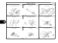
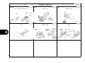
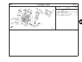
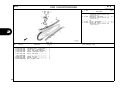
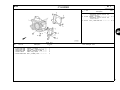
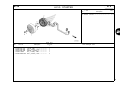
1
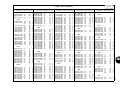
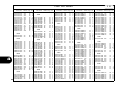
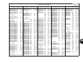
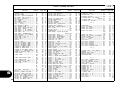
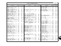
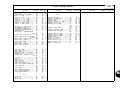
ACA125CBF ACA125CBF E 1 18K27EM1 © Honda Motor Co., Ltd. 2013 FOREWORD INDEX 1 ENGINE GROUP 2 FRAME GROUP 3 PART NUMBER INDEX 4 PART NAME INDEX 5 B1 CONTENTS Instruction for use of parts catalogue Page • This parts catalogue has been created as of May 20, 2013. • Since this date, the sales practice for repair parts may have been changed or the parts may have been eliminated (listed for those not for sale). • The modified information is reflected on the latest Electronic Parts Catalogue (EPC). Also, refer to the parts catalogue news for any change. • See the parts catalogue news for any revision that is made after May 20, 2013. • Always specify the part number when ordering a part. • Check the model, type, serial numbers, color, maker, and the size as needed before ordering a part. • Note that the illustrations (part drawings) can differ from the actual parts in shape. They are given just to help you to refer to the parts. Address No. Instruction for use of parts catalogue ......................... 1 How to refer to the part information ............................ 2 Part catalogue structure ............................................. 3 When the parts were revised...................................... 4 Abbreviations used in the parts catalogue.................. 4 Part block and serial number check ........................... 5 Models, parts catalogue codes and applicable B B B B B B 1 2 3 4 4 5 serial numbers ........................................................... 6 B 6 B 7 hose......................................................................... 10 B10 B14 C 3 D 1 F 1 I 1 J 1 Color chart .................................................................. 7 Fuel hose, general purpose hoses and vinyl FLAT RATE SERVICE TIME.................................... 14 Illustrated index ........................................................ 19 ENGINE GROUP..................................................... 25 FRAME GROUP...................................................... 46 PART NO. INDEX..................................................... 85 PART NAME INDEX................................................. 89 1 1 2 3 4 5 • When modifications or additions to this parts catalogue are made, a revised edition will be issued at an appropriate time, with successively progressing revision numbers on the cover. We recommend obtaining such revisions in order to keep your parts catalogue up-to-date at all times. To check whether a parts catalogue revision has been issued, please contact your Honda distributor. Initial version issue date May 20, 2013 Honda Motor Co., Ltd. 1 B 2 How to refer to the part information Reference with “Illustrated index” 1 Reference with “Part number index” Reference with “Part name index” 2 B 3 Address number Part catalogue structure • Address No. is provided (in place of the page No.) to help you refer to the part with the part No. or part name. 1 Block title Block number Service item/Flat rate time Reference number • Title number marked with the parenthesis or parentheses indicates that it continues from the previous page. Part number Description Assemblies Honda color code • Sections framed with broken lines in the exploded view drawings are available as complete assemblies. (Their individual parts can also be obtained.) Color description Note • Notes are shown with the parentheses in the part name column. Required quantity • Reqd. QTY shown in the parenthesis or parentheses indicates the optional part. • Reqd. QTY marked with “N” indicates the optional part that should be selected as needed. • Reqd. QTY indicates the number of the part used in the block. Serial number Parts catalogue code • When the parts catalogue code column is blank, it indicates that the part is applicable to all codes. • Parts enclosed within a dotted line different block. are covered in a • A hollow arrow indicates the block No. for the parts enclosed within a dotted line . • A solid arrow indicates the block No. the part in question is connected to. 3 B 4 When the parts were revised Abbreviations used in the parts catalogue 1 Be sure to check the serial number!! RIGHT is abbreviated as “R.” “L.” stands for LEFT * “L.” or “R.” in the description of a part stands for the LEFT hand side or the RIGHT hand side. Determine the left or right as if you were in the motorcycle seat. • The following abbreviations are used in this parts catalogue. The number has been When shown at the left side, When shown at the right side, used from the initial model it is applicable to the models it is applicable to the models without revision. o f N o . 1 0 0 8 0 0 1 a n d t h e up to No.1008000. subsequent numbers. • The parts listed with "###" at the end of the parts name have limited supply period (parts not for sale). A ........... Ampere ABS ....... Anti-lock brake system A.C. ....... Alternating current A.M. ...... Attaching mark ASSY. .... Assembly C.D.I. ..... Capacitive discharge ignition COMP. ... Complete D.C. ....... Direct current EX. ........ Exhaust FR. ........ Front G ........... Gram HEX. ..... Hexagonal IN. ......... Inlet KPH ...... Kilometers per hour 4 L. ............Left L (100L) .Link (100 Links) L.E.D. .....Light emitted diode MM .........Millimeter MPH .......Miles per hour R. ...........Right RR. .........Rear STD. .......Standard T (22T) ...Tooth (22 Teeth) TCS ........Traction control system T.M. ........Transcript mark V ............Volt W ...........Watt WL .........With labelling WOL .......Without labelling B 5 Part block and serial number check Part block Required serial number Check point Engine parts Frame parts E-2~ Throttle body parts E-22 Engine serial number Throttle body serial number Frame serial number 2 1 1 F-1~ 3 3 1 2 5 B 6 Models, parts catalogue codes and applicable serial numbers 1 Models, parts catalogue codes and applicable serial Nos. given in this parts catalogue can be identified as follows. Parts with parts catalogue codes are exclusive for models destined for countries designated. If no area codes are listed, parts are for common use. Model Area code Type ACA125CBFE MA Malaysia Applicable engine serial No. Applicable frame serial No. Applicable throttle body identification No. GQYAA A * Of carburetor/throttle body identification numbers, only the portions underlined in the example below are used for registration. GQYAA A KC 6 B 7 Color chart 1 • When ordering a colored part, refer to the chart below and use a part number consisting of the relevant basic part number to which has been added a part color code. ACA125CBF (ACA125CBFE) MODEL ACA125CBFE COLOR CODE No. Name of colored parts Basic part No. Pearl magellanic black Pearl magellanic black Pearl metalloid white NH-A69P NH-A69P NH-A96P NHA69E NHA69F NHA96 Applicable model Initial applicable model Final applicable model Applicable block No. Ref.No. 1 CAP, HANDLE COVER 53207-KZL-840 ZA ZA ZA F-4 26 2 COVER COMP., SPEEDOMETER 53115-K27-V00 ZR ZP ZQ F-9 3 3 COVER SET, FR. HANDLE 53210-K27-M00 ZA ZA ZA F-9 7 4 COVER SET, FR. TOP 64300-K27-V00 ZM ZK ZL F-12 1 5 COVER SET, L. BODY 83650-K27-M00 ZC ZA ZB F-15 14 6 COVER SET, L. FR. 64600-K27-M00 ZC ZA ZB F-12 8 7 COVER SET, MAIN PIPE UPPER 64320-K27-M00 ZA ZA ZA F-13 1 8 COVER SET, R. BODY 83550-K27-M00 ZC ZA ZB F-15 12 9 COVER SET, R. FR. 64500-K27-M00 ZC ZA ZB F-12 3 10 COVER, CENTER 64340-K27-V00 ZM ZK ZL F-15 2 11 COVER, FR. HANDLE 53205-K27-V00 ZB ZB ZB F-9 4 12 COVER, FR. TOP 64302-K27-V00 ZM ZK ZL F-12 2 13 COVER, L. BODY 83600-K27-V00 ZD ZD ZC F-15 13 14 COVER, L. FR. 64502-K27-V00 ZD ZD ZC F-12 5 15 COVER, L. FR. LOWER 64520-K27-V00 ZD ZD ZC F-12 7 16 COVER, L. MAIN PIPE SIDE 64420-K27-V00 ZM ZK ZL F-13 6 17 COVER, L. UNDER SIDE 64431-K27-V00 ZH ZJ ZJ F-14 4 18 COVER, MAIN KEY LAMP 64331-K27-V10 ZB ZB ZB F-13 3 19 COVER, MAIN PIPE UPPER 64330-K27-V00 ZB ZB ZB F-13 2 20 COVER, R. BODY 83500-K27-V00 ZD ZD ZC F-15 11 7 B 8 ACA125CBF (ACA125CBFE) MODEL 1 ACA125CBFE COLOR CODE No. Pearl magellanic black Pearl metalloid white NH-A69P NH-A69P NH-A96P Applicable model Initial applicable model Final applicable model Applicable block No. Ref.No. F-12 4 Basic part No. NHA69E NHA69F NHA96 COVER, R. FR. 64501-K27-V00 ZD ZD ZC 22 COVER, R. FR. LOWER 64510-K27-V00 ZD ZD ZC F-12 6 23 COVER, R. MAIN PIPE SIDE 64410-K27-V00 ZM ZK ZL F-13 5 24 COVER, R. UNDER SIDE 64421-K27-V00 ZG ZH ZH F-14 3 25 COVER, RR. HANDLE 53206-K27-V00 ZB ZB ZB F-9 5 21 Name of colored parts Pearl magellanic black 26 COVER, TAILLIGHT UPPER 83751-K27-V00 ZH ZH ZG F-15 15 27 FENDER SET, FR. 61110-K27-M00 ZC ZA ZB F-11 3 28 FENDER SET, RR. 80110-K27-V00 ZA ZA ZA F-39 6 29 FENDER, FR. 61100-K27-V00 ZP ZM ZN F-11 1 30 GARNISH, HANDLE FR. COVER 53207-K27-V00 ZN ZL ZM F-9 6 31 LID COMP., FUEL 64750-K27-V00 ZM ZK ZL F-15 9 32 MARK 86645-K27-M00 ZA ZA ZA F-48 6 33 MARK, COMBINATION BRAKE 86611-K27-M00 ZA ZA ZA F-48 2 34 MARK, DELUXE 86646-K27-M00 ZB ZB ZA F-48 7 35 MARK, FI IDLING STOP 86644-KZR-770 ZA ZA ZA F-48 5 36 MARK, HONDA 87110-KVB-900 ZA ZA ZA F-48 13 37 PLUG, HOLE 90656-GCC-000 ZC ZC ZC F-24 13 38 RAIL, RR. GRAB 84100-K27-V00 ZE ZE ZG F-24 10 39 SEAT COMP., DOUBLE 77200-K27-V00 ZD ZD ZC F-24 2 40 STEP, L. FLOOR 64321-K27-V00 ZA ZA ZA F-14 2 41 STEP, R. FLOOR 64311-K27-V00 ZA ZA ZA F-14 1 42 STRIPE A, L. FR. COVER 86648-K27-M00 ZC ZA ZB F-48 9 43 STRIPE A, R. FR. COVER 86647-K27-M00 ZC ZA ZB F-48 8 44 STRIPE B, L. FR. COVER 86644-K27-M00 ZC ZA ZB F-48 4 8 B 9 ACA125CBF (ACA125CBFE) MODEL ACA125CBFE Pearl magellanic black Pearl magellanic black Pearl metalloid white NH-A69P NH-A69P NH-A96P Basic part No. NHA69E NHA69F NHA96 COLOR CODE No. Name of colored parts Applicable model Initial applicable model Final applicable model 1 Applicable block No. Ref.No. 45 STRIPE B, R. FR. COVER 86643-K27-M00 ZC ZA ZB F-48 3 46 STRIPE, L. BODY COVER 86832-K27-M00 ZC ZA ZB F-48 11 47 STRIPE, R. BODY COVER 86831-K27-M00 ZC ZA ZB F-48 10 48 WHEEL SUB ASSY., FR. 44650-K27-M00 ZA ZA ZA F-20-20 6 49 WHEEL SUB ASSY., RR. 42650-K27-M00 ZA ZA ZA F-22-10 2 9 B10 Fuel hose, general purpose hoses and vinyl hose 1 • The standard part fuel hose, general purpose hose and vinyl hose may be substituted by the coiled bulk part. • When ordering the standard part fuel hose, general purpose hose and vinyl hose use the bulk part number written in the parts catalogue in brackets ( ) underneath the part name, or use the catalogue below. (The bulk part standard length is 1 m, however, those displayed in the catalogue < > are available in 3 m and 8 m lengths.) • When exchanging the hose, cut and use at the specified length as mentioned in the part name. (For the method of cutting the bulk part, and method of filling out orders etc., please refer to the service manual and the instructions issued with the bulk part.) • The list below is a catalogue of the standard part numbers and bulk part numbers. Note that those numbers are applicable to the listed replacement parts only. Fuel hoses/Tubes Fuel hoses/Tubes Bulk part Standard part No. Bulk part No. Inner diameter (mm) 95001-30xxx-2x 95001-30xxx-3x 95001-30xxx-4x 95001-30001-20M 95001-30001-30M 95001-30001-40M 95001-35001-50M <95001-35003-50M> 95001-35001-60M <95001-35003-60M> 95001-35001-60M <95001-35003-60M> 95001-35001-50M <95001-35003-50M> 95001-35001-60M <95001-35003-60M> 95001-45001-50M <95001-45003-50M> 95001-45001-60M <95001-45003-60M> <95001-45008-60M> 95001-45001-60M <95001-45003-60M> <95001-45008-60M> 95001-45001-50M <95001-45003-50M> 95001-45001-60M <95001-45003-60M> <95001-45008-60M> 95001-55001-50M <95001-55003-50M> <95001-55008-50M> 3.0 3.0 3.0 95001-35xxx-2x 95001-35xxx-3x 95001-35xxx-4x 95001-35xxx-5x 95001-35xxx-6x 95001-45xxx-2x 95001-45xxx-3x 95001-45xxx-4x 95001-45xxx-5x 95001-45xxx-6x 95001-55xxx-2x 3.5 3.5 3.5 3.5 3.5 4.5 4.5 4.5 4.5 4.5 5.5 Bulk part Length (m) 1 1 1 1 3 1 3 1 3 1 3 1 3 1 3 1 3 8 1 3 8 1 3 1 3 8 1 3 8 Standard part No. 95001-55xxx-3x 95001-55xxx-4x 95001-55xxx-5x 95001-55xxx-6x 95001-75xxx-2x 95001-75xxx-3x 95001-75xxx-4x 95001-75xxx-5x 95001-75xxx-6x 95001-80xxx-2x 95001-80xxx-3x 95001-80xxx-4x 95001-80xxx-5x 95001-80xxx-6x 10 Bulk part No. 95001-55001-60M <95001-55003-60M> <95001-55008-60M> 95001-55001-60M <95001-55003-60M> <95001-55008-60M> 95001-55001-50M <95001-55003-50M> <95001-55008-50M> 95001-55001-60M <95001-55003-60M> <95001-55008-60M> 95001-75001-50M <95001-75003-50M> 95001-75001-60M <95001-75003-60M> <95001-75008-60M> 95001-75001-60M <95001-75003-60M> <95001-75008-60M> 95001-75001-50M <95001-75003-50M> 95001-75001-60M <95001-75003-60M> <95001-75008-60M> 95001-80001-50M 95001-80001-60M 95001-80001-60M 95001-80001-50M 95001-80001-60M Inner diameter (mm) 5.5 5.5 5.5 5.5 7.5 7.5 7.5 7.5 7.5 8.0 8.0 8.0 8.0 8.0 Length (m) 1 3 8 1 3 8 1 3 8 1 3 8 1 3 1 3 8 1 3 8 1 3 1 3 8 1 1 1 1 1 B11 Vinyl tube Vinyl tube Bulk part Standard part No. Bulk part No. 95003-01001-60M 95003-01xxx-3x <95003-01003-60M> Inner Outer dia- meter dia-meter (mm) (mm) 2.9 Vinyl tube Bulk part Length (m) Standard part No. Bulk part No. Inner Outer dia- meter dia-meter (mm) (mm) Bulk part Length (m) 6.8 1 3 95003-14001-10M 95003-14xxx-1x <95003-14003-10M> 6.0 9.0 1 3 95003-14001-10M 95003-14xxx-20 <95003-14003-10M> 6.0 9.0 1 3 Standard part No. Bulk part No. Inner Outer dia- meter dia-meter (mm) (mm) 95003-36001-10M 95003-36xxx-1x <95003-36003-10M> <95003-36008-10M> 11.0 13.0 1 3 8 95003-36001-10M 95003-36xxx-20 <95003-36003-10M> <95003-36008-10M> 11.0 13.0 1 3 8 95003-37001-60M 95003-37xxx-3x 95003-37003-60M> 11.0 15.0 1 3 95003-37001-60M 95003-37xxx-60 <95003-37003-60M> 11.0 15.0 1 3 95003-01001-60M 95003-01xxx-60 <95003-01003-60M> 2.9 6.8 1 3 95003-03001-60M 95003-03xxx-3x <95003-03003-60M> 3.0 6.0 1 3 95003-14001-60M 95003-14xxx-3x <95003-14003-60M> 6.0 9.0 1 3 95003-03001-60M 95003-03xxx-60 <95003-03003-60M> 3.0 6.0 1 3 95003-17001-10M 95003-17xxx-1x <95003-17003-10M> 7.0 9.0 1 3 95003-05001-60M 95003-05xxx-3x <95003-05003-60M> <95003-05008-60M> 3.5 6.5 1 3 8 95003-19001-10M 95003-19xxx-1x <95003-19003-10M> <95003-19008-10M> 7.0 11.0 1 3 8 13.0 11.0 1 3 8 1 3 6.5 95003-19001-10M 95003-19xxx-20 <95003-19003-10M> <95003-19008-10M> 95003-38001-10M 95003-38xxx-1x <95003-38003-10M> 12.0 1 3 8 95003-38001-10M 95003-38xxx-20 <95003-38003-10M> 12.0 13.0 1 3 95003-19001-60M 95003-19xxx-3x <95003-19003-60M> <95003-19008-60M> 7.0 11.0 1 3 8 95003-39001-10M 95003-39xxx-1x <95003-39003-10M> 12.0 14.0 1 3 12.0 14.0 1 3 11.0 1 3 8 95003-39001-10M 95003-39xxx-20 <95003-39003-10M> 7.0 95003-40001-10M 95003-40xxx-20 <95003-40003-10M> 12.0 16.0 1 3 9.0 1 3 95003-40001-60M 95003-40xxx-3x <95003-40003-60M> 12.0 16.0 1 3 9.0 1 3 95003-40001-60M 95003-40xxx-60 <95003-40003-60M> 12.0 16.0 1 3 12.0 1 3 95003-43001-10M 95003-43xxx-1x <95003-43003-10M> <95003-43008-10M> 13.0 15.0 1 3 8 95003-43001-10M 95003-43xxx-20 <95003-43003-10M> <95003-43008-10M> 13.0 15.0 1 3 8 95003-45001-10M 95003-45xxx-1x <95003-45003-10M> <95003-45008-10M> 14.0 18.0 1 3 8 95003-05001-60M 95003-05xxx-60 <95003-05003-60M> <95003-05008-60M> 3.5 95003-07001-10M 95003-07xxx-1x <95003-07003-10M> <95003-07008-10M> 4.0 7.0 1 3 8 95003-07001-10M 95003-07xxx-20 <95003-07003-10M> <95003-07008-10M> 4.0 7.0 1 3 8 95003-19001-60M 95003-19xxx-60 <95003-19003-60M> <95003-19008-60M> 7.0 1 3 8 95003-21001-10M 95003-21xxx-1x <95003-21003-10M> 7.0 95003-07001-60M 95003-07xxx-3x <95003-07003-60M> <95003-07008-60M> 4.0 95003-07001-60M 95003-07xxx-60 <95003-07003-60M> <95003-07008-60M> 4.0 7.0 1 3 8 95003-07001-70M 95003-07xxx-7x <95003-07003-70M> <95003-07008-70M> 4.0 7.0 1 3 8 95003-23001-10M 95003-23xxx-20 <95003-23003-10M> 8.0 12.0 1 3 95003-23001-60M 95003-23xxx-3x <95003-23003-60M> <95003-23008-60M> 8.0 12.0 1 3 8 95003-23001-60M 95003-23xxx-60 <95003-23003-60M> <95003-23008-60M> 8.0 12.0 1 3 8 95003-25001-10M 95003-25xxx-1x <95003-25003-10M> 9.0 11.0 1 3 95003-45001-10M 95003-45xxx-20 <95003-45003-10M> <95003-45008-10M> 14.0 18.0 1 3 8 95003-25001-10M 95003-25xxx-20 <95003-25003-10M> 9.0 11.0 1 3 95003-50001-10M 95003-50xxx-1x <95003-50003-10M> 16.0 19.0 1 3 95003-25001-60M 95003-25xxx-3x <95003-25003-60M> 9.0 11.0 1 3 95003-50001-10M 95003-50xxx-20 <95003-50003-10M> 16.0 19.0 1 3 95003-25001-70M 95003-25xxx-7x <95003-25003-70M> 9.0 11.0 1 3 95003-50001-60M 95003-50xxx-3x <95003-50003-60M> 16.0 19.0 1 3 95003-27001-10M 95003-27xxx-1x <95003-27003-10M> 9.0 13.0 1 3 95003-55001-10M 95003-55xxx-1x <95003-55003-10M> 17.5 20.5 1 3 95003-27001-10M 95003-27xxx-20 <95003-27003-10M> 9.0 13.0 1 3 95003-55001-10M 95003-55xxx-20 <95003-55003-10M> 17.5 20.5 1 3 95003-27001-60M 95003-27xxx-3x <95003-27003-60M> 9.0 13.0 1 3 95003-60001-10M 95003-60xxx-1x <95003-60003-10M> 22.0 27.0 1 3 95003-27001-60M 95003-27xxx-60 <95003-27003-60M> 9.0 13.0 1 3 95003-60001-10M 95003-60xxx-20 <95003-60003-10M> 22.0 27.0 1 3 95003-60001-60M 95003-60xxx-3x <95003-60003-60M> 22.0 27.0 1 3 95003-60001-60M 95003-60xxx-60 <95003-60003-60M> 22.0 27.0 1 3 95003-08001-10M 95003-08xxx-1x <95003-08003-10M> <95003-08008-10M> 4.5 6.5 1 3 8 95003-09001-60M 95003-09xxx-3x <95003-09003-60M> 4.5 8.0 1 3 95003-09001-60M 95003-09xxx-60 <95003-09003-60M> 4.5 8.0 1 3 95003-10001-10M 95003-10xxx-1x <95003-10003-10M> 5.0 8.0 1 3 8.0 1 3 8.0 1 3 8.0 1 3 95003-10001-10M 95003-10xxx-20 <95003-10003-10M> 95003-10001-60M 95003-10xxx-3x <95003-10003-60M> 95003-10001-60M 95003-10xxx-60 <95003-10003-60M> 5.0 5.0 5.0 95003-11001-60M 95003-11xxx-3x <95003-11003-60M> <95003-11008-60M> 5.0 9.0 1 3 8 95003-11001-60M 95003-11xxx-60 <95003-11003-60M> <95003-11008-60M> 5.0 9.0 1 3 8 95003-12001-10M 95003-12xxx-1x <95003-12003-10M> <95003-12008-10M> 5.0 7.0 1 3 8 95003-12001-10M 95003-12xxx-20 <95003-12003-10M> <95003-12008-10M> 5.0 7.0 1 3 8 95003-21001-10M 95003-21xxx-20 <95003-21003-10M> 95003-23001-10M 95003-23xxx-1x <95003-23003-10M> 8.0 8.0 8.0 95003-33001-10M 95003-33xxx-1x <95003-33003-10M> 10.0 14.0 1 3 95003-33001-10M 95003-33xxx-20 <95003-33003-10M> 10.0 14.0 1 3 1 Length (m) 11 B12 General purpose hoses 1 General purpose hoses Bulk part Bulk part Standard part No. Bulk part No. Inner diameter (mm) Length (m) 95005-11xxx-3x 95005-11xxx-5x 95005-11001-30M 95005-11001-50M 95005-12001-10M <95005-12003-10M> 95005-12001-20M 95005-12001-30M 95005-12001-50M 95005-14001-10M 95005-14001-20M <95005-14003-20M> 95005-14001-30M 95005-14001-50M 95005-17001-10M 95005-17001-20M 95005-17001-30M 95005-17001-50M 95005-30001-30M 95005-30001-50M 95005-35001-10M <95005-35003-10M> <95005-35008-10M> 95005-35001-20M 95005-35001-30M 95005-35001-10M <95005-35003-10M> <95005-35008-10M> 95005-35001-50M 95005-45001-10M <95005-45003-10M> <95005-45008-10M> 95005-45001-20M 95005-45001-30M 11.0 11.0 1 1 1 3 1 1 1 1 1 3 1 1 1 1 1 1 1 1 1 3 8 1 1 1 3 8 1 1 3 8 1 1 95005-12xxx-1x 95005-12xxx-2x 95005-12xxx-3x 95005-12xxx-5x 95005-14xxx-1x 95005-14xxx-2x 95005-14xxx-3x 95005-14xxx-5x 95005-17xxx-1x 95005-17xxx-2x 95005-17xxx-3x 95005-17xxx-5x 95005-30xxx-3x 95005-30xxx-5x 95005-35xxx-1x 95005-35xxx-2x 95005-35xxx-3x 95005-35xxx-4x 95005-35xxx-5x 95005-45xxx-1x 95005-45xxx-2x 95005-45xxx-3x 12.0 12.0 12.0 12.0 14.0 14.0 14.0 14.0 17.0 17.0 17.0 17.0 3.0 3.0 3.5 3.5 3.5 3.5 3.5 4.5 4.5 4.5 Standard part No. 95005-45xxx-4x 95005-45xxx-5x 95005-50xxx-3x 95005-50xxx-5x 95005-55xxx-1x 95005-55xxx-2x 95005-55xxx-4x 95005-65xxx-1x 95005-65xxx-2x 95005-70xxx-3x 95005-70xxx-5x 95005-75xxx-1x 95005-75xxx-2x 95005-80xxx-1x 95005-80xxx-2x 95005-80xxx-3x 95005-80xxx-5x 95005-91xxx-3x 95005-91xxx-5x 95005-92xxx-3x 95005-92xxx-5x Bulk part No. 95005-45001-10M <95005-45003-10M> <95005-45008-10M> 95005-45001-50M 95005-50001-30M <95005-50003-30M> 95005-50001-50M 95005-55001-10M <95005-55003-10M> <95005-55008-10M> 95005-55001-20M <95005-55003-20M> 95005-55001-10M <95005-55003-10M> <95005-55008-10M> 95005-65001-10M <95005-65003-10M> 95005-65001-20M 95005-70001-30M <95005-70003-30M> 95005-70001-50M 95005-75001-10M <95005-75003-10M> 95005-75001-20M 95005-80001-10M <95005-80003-10M> 95005-80001-20M 95005-80001-30M 95005-80001-50M 95005-91001-30M 95005-91001-50M 95005-92001-30M 95005-92001-50M Inner diameter (mm) 4.5 4.5 5.0 5.0 5.3 5.3 5.3 6.5 6.5 7.0 7.0 7.3 7.3 8.0 8.0 8.0 8.0 12.0 12.0 12.0 12.0 Length (m) 1 3 8 1 1 3 1 1 3 8 1 3 1 3 8 1 3 1 1 3 1 1 3 1 1 3 1 1 1 1 1 1 1 NOTE: X is displayed to represent the omitted numerals and letters of the roman alphabet. CAUTION: It is DANGEROUS to confuse the fuel hose with the general purpose hose or vinyl hose. Never use a general purpose hose or vinyl hose in place of a fuel hose or vice versa. Always use the correct bulk part in the parts catalogue, according to the service manual or the instructions issued with the bulk part. 12 B13 • Bulk part number of fuel hose, general purpose hose and vinyl hose. 1 (Example) 95001-75001-50M Bulk part number: Refers to the bulk part. Marking code (hose type): (fuel hose and general purpose hose) Change code (for added hose): (Vinyl hose) • Indicates number mark or change sequence, however, the code for the bulk part must be strictly 0 (zero). Types of code: • Fuel hose 2: Red outside braid (3 mm inside dia. only) 5: Black inside braid 3: Red (3 mm inside dia. only) 4: Ash gray with red stripe (3 mm inside dia. only) 6: Black • Vinyl hose 1: Clear 2: Black 3: Light red 6: Light red 7: Pale black • General hose 1: Ash gray 2: Ash gray 3: Black 5: Black Lengths: 001: 1 m (standard) 003: 3 m 008: 8 m I.D code: (fuel hose and general purpose hose) 30: 3.0 mm 11: 11 mm 35: 3.5 mm 91: 12 mm (outside dia. 15) mm 45: 4.5 mm 92: 12 mm (outside dia. 16) mm 50: 5.0 mm 12: 12 mm (outside dia. 17) mm 55: 5.3 mm, 5.5 mm 14: 14 mm 65: 6.5 mm 17: 17 mm 70: 7.0 mm 75: 7.3 mm, 7.5 mm 80: 8.0 mm ID./OD. code: (vinyl hose) 01: ID. 2.9, OD. 6.8 mm 03: ID. 3.0, OD. 6.0 mm 05: ID. 3.5, OD. 6.5 mm 07: ID. 4.0, OD. 7.0 mm 08: ID. 4.5, OD. 6.5 mm 09: ID. 4.5, OD. 8.0 mm 12: ID. 5.0, OD. 7.0 mm 10: ID. 5.0, OD. 8.0 mm 11: ID. 5.0, OD. 9.0 mm 14: ID. 6.0, 17: ID. 7.0, 19: ID. 7.0, 21: ID. 8.0, 23: ID. 8.0, 25: ID. 9.0, 27: ID. 9.0, 33: ID. 10.0, 36: ID. 11.0, OD. 9.0 mm OD. 9.0 mm OD. 11.0 mm OD. 9.0 mm OD. 12.0 mm OD. 11.0 mm OD. 13.0 mm OD. 14.0 mm OD. 13.0 mm 37: ID. 11.0, 38: ID. 12.0, 39: ID. 12.0, 40: ID. 12.0, 43: ID. 13.0, 45: ID. 14.0, 50: ID. 16.0, 55: ID. 17.5, 60: ID. 22.0, OD. 15.0 mm OD. 13.0 mm OD. 14.0 mm OD. 16.0 mm OD. 15.0 mm OD. 18.0 mm OD. 19.0 mm OD. 20.5 mm OD. 27.0 mm Hose type: 1: Fuel hose 3: Vinyl hose 5: General hose 13 B14 Editorial style FLAT RATE SERVICE TIME 1 Flat rate service time (FRT) means the standard time required to service a MC, which is listed in this manual to help the dealers control the actual working process and calculate the service charge by using it as a guide. The service items shown in the text are listed with the exchange work time for the repair sales parts as the subject. Other representative service items not using repair parts (removal/ installation, adjustment, inspection/measuring, and other work) are listed collectively in the list in the preface, classified according to the work. FRT setting system FRT setting standard Net service time Removal, Disassembly/reassembly, Installation Inspection, Measurement, Adjustment, Confirmation Diagnosis/troubleshooting (Electric system) • Decimal system (in unit of 0.1) is adopted to set FRT as it is convenient to calculate the wage. Example: (0.1) 6 minutes, (0.2) 12 minutes [Labor cost per hour] x [FRT] = [Wage] • FRT is set with a hand tool. • Service items and FRT can be subject to change depending on development of tools and service equipment and improvement in service procedure. Completion inspection Float time Preparation (Process check, Confirmation arrangement for necessary tools) Related work (Transfer of vehicles) * Float time is set by multiplying the net service time by a given coefficient. 14 B15 Work procedure Service item whose FRT is not presented • As the work procedure is set with the work time according to the method in the separate Service Manual, refer to this Manual as required. • Accessories and service parts that are not listed to use in this manual. • Work methods permitting servicing in the shortest time still permitting assurance of safe work and product warranty are used for the setting of service items not listed in the Service Manual. • Work basically is to be performed by one person, and when two or more people are required, setting is done as the total time for the number of people. 1 • Locations with little aging deterioration or breakage during normal use. • Service work that can be finished by one touch. • Service work that is seldom done (i.e. extremely small causes of trouble and service frequency). * When FRT is not presented, please calculate wages based on appropriate actual work time • The set value for the technological level of the workers uses a person with three years of experience in the repair of Honda vehicles as the standard. Operation not included of FRT • Special tools and service equipment used to set FRT are those specified or recommended in Service Manual. • Oil and coolant water draining, Waiting time for warming up operation and etc.. • Additional operation that involves removal/installation of standard exterior equipment. • Indirect time spent for service by visiting the customer, trade-in, and delivery of a MC. • Indirect time required for ordering and delivery of parts. • Cost for grease, adhesive agent, etc. used for service work. 15 B16 Explanation of FRT by using an example (The example may differ from the actual presented items) 1 Ref. No. L.O.N. (Relative ref. Number) Description F.R.T. (1, 3, 4, 7) 2 111118 CAMSHAFT • • • • • • • • • • • • • • 4.5 • Includes: Valve clearance adjustment 111118A Replace rocker arm add • • • • • • • • • • • • • • • • • • • • • • • • • 1.0 Reference No. of the illustration of part that shows location of the replacement work. FRT is an abbreviation of Flat Rate Time indicating the standard service time required for the replacement. Indicating work contents that are included in the service item. Indicating a reference No. whose operation and time are the same as FRT4.5 for the camshaft. (The application range is limited to the service items without an LON setting within a same block.) How to refer to the service item by using the sample (camshaft replacement) Open to the page of the block where the camshaft's spare part illustration is shown. Look for the camshaft illustration, and refer to the service item and FRT that agree with the reference No. LON is an abbreviation of Labor Operation Number, and it is a classification of the service items by the work unit code. The same operation code is used regardless of the models. Standard operation is indicated with 6 digits code, and additional operation is indicated with 7 digits code. Indicating the camshaft replacement and FRT4.5. Indicating FRT1.0 that will be added when additional operation (replace rocker arm) is done in association with camshaft replacement. 16 C 1 Indication mark for the listing of service items that continues to the following page Ref. L.O.N. No. 2 111118 1 (Relative ref. Number) 18 • • Code • • • 1 Engine 2 Transmission 3 Fuel & Exhaust 4 Frame & Body 5 Steering/Suspension 6 Electrical 7 Wheels/Brakes 8 Controls/instrument 9 - 0 - Mark indicated at the last line. Indication of the block with no setting of FRT L.O.N. (Relative ref. Number) F.R.T. Description NO INFORMATION • • • • • • • • • • • • • • • • • • • • LON code system 1 11 1 18 A a b c d e 1 c • Ref. A a) Category codes and classification CAMSHAFT • • • • • • • • • • • • • • • 4.5 + No. 1 a F.R.T. Description 11 Category c) Operation codes and classification Code Operation category 1 Replace, Removal/Installation, Change a) Category code..................... Engine 2 Overhaul b) Location/function code ........ Engine upper 3 Adjust, Balance c) Operation code.................... Replace 4 (Paint-related work: Top-coat) d) Operation sequence number (Unit code can be shown with alphabet) ......................... camshaft (No regular rule of code) 5 Test, Inspect/diagnose, Measurement, Check 6 (Overhaul-related work: Rebore) 7 (Overhaul-related work: Reseal) 8 (Resurface) 9 (Paint-related work: Refinish) 0 Repair, Cleaning, Air bleeding e) Additional code ................... replace rocker arm (No regular rule of code) 17 C 2 Major service items without using spare parts (1) Removal/Installation, (2) Adjustment, (3) Inspection/Measurement, (5) Other work 1 E: Engine, F: Frame * OPERATIONS OTHER THAN REPLACING PARTS (1) Removal and installation Set for the configuration with the parts removed from the vehicle. LON 1101E5 1111K0 E 3111D5 1101E6 1151E6 DESCRIPTION TILTING ENGINE ASSEMBLY- REMOVAL/INSTALLATION INCLUDES: All necessary adjustment CYLINDER HEAD ASSEMBLY- REMOVAL/INSTALLATION INCLUDES: Engine removal and installation THROTTLE BODY ASSEMBLY- REMOVAL/INSTALLATION CRANKCASE SEPARATION INCLUDES: Engine removal and installation RADIATOR ASSEMBLY- REMOVAL/INSTALLATION FRT 1.9 F E 4.3 E 0.4 FRT 6143A1 SPARK PLUG-ADJUSTMENT/CLEANING 0.1 1113A0 VALVE CLEARANCE-ADJUSTMENT NOTE: For 1 vehicle 1.0 6163A0 HEADLIGHT-AIMING 0.1 7113A1 REAR BRAKE-ADJUSTMENT EXCLUDES: Rear brake shoe adjustment 0.1 THROTTLE OPERATION-ADJUSTMENT COMPRESSION PRESSURE-MEASUREMENT 0.1 6145A0 IGNITION TIMING-INSPECTION 0.4 6105A0 BATTERY-CHECKING OF ELECTROLYTE LEVEL & CHARGE 0.2 LON 0.1 3113A3 1115A0 (5) Other work ENGINE IDLE-ADJUSTMENT 7113A1A Adjust the equalizer add FRT 0.7 3143A0 F DESCRIPTION 3.2 F DESCRIPTION LON E (2) Adjustment LON (3) Inspection, Measurement DESCRIPTION FRT 1130A1 OIL FILTER SCREEN-CLEANING 0.2 7110A0 FRONT BRAKE-AIR BLEEDING 0.2 1151E7 RADIATOR COOLANT-CHANGE 0.3 3115A3 ECM INITIALIZE LEARNING 0.2 0.2 0.1 18 ENGINE GROUP E-2 D 1 E-3 CYLINDER HEAD COVER C 3 D 2 E-4 CYLINDER HEAD D 4 CAMSHAFT/VALVE 2 E-5 D 6 E-6 CAM CHAIN/TENSIONER E-10 E-9 CYLINDER D 9 A.C.G. STARTER D 7 D 8 WATER PUMP E-11 D10 OIL PUMP E-13 D11 LEFT SIDE COVER 19 C 4 ENGINE GROUP E-14 D12 E-16 RADIATOR D13 E-17 DRIVE FACE D14 DRIVEN FACE 2 E-17-10 D15 E-19-10 TRANSMISSION E-20 E 4 CRANKSHAFT/PISTON D16 RIGHT CRANKCASE E-22 20 E 2 LEFT CRANKCASE E 5 THROTTLE BODY/FUEL INJECTOR E-19-20 FRAME GROUP F-1 F 1 F-2 HEADLIGHT F-5 C 5 F 2 F-4 METER F 5 F-9 FRONT BRAKE MASTER CYLINDER F 3 HANDLE LEVER/SWITCH/CABLE F 6 F-10 HANDLE PIPE/HANDLE COVER F 8 STEERING STEM 3 F-11 F 9 FRONT FENDER F-12 F10 FRONT COVER F-13 F12 MAIN PIPE COVER 21 C 6 FRAME GROUP F-14 F13 F-14-10 FLOOR STEP/UNDER COVER F-17 F14 F-15 PILLION STEP G 1 F-18 FRONT FORK F15 BODY COVER G 2 F-20-20 FRONT BRAKE CALIPER G 3 FRONT WHEEL 3 F-22-10 G 4 REAR WHEEL F-23 G 5 SWINGARM G 6 SEAT/LUGGAGE BOX 22 F-24 C 7 FRAME GROUP F-26 G 7 F-28 FUEL TANK F-35 G 8 F-30 AIR CLEANER G10 F-36 STAND/KICK STARTER ARM G 9 EXHAUST MUFFLER G11 F-38-10 REAR CUSHION G12 REAR COMBINATION LIGHT 3 F-39 G13 REAR FENDER/LICENSE LIGHT F-40 G14 BATTERY F-41 G15 WIRE HARNESS 23 C 8 FRAME GROUP F-41-10 H 1 F-42 SUB HARNESS/IGNITION COIL F-46 H 4 TOOL H 2 F-43 FRAME BODY F-47 H 5 CAUTION LABEL F-48 H 6 MARK 3 24 H 3 RESERVE TANK E-2 D 1 CYLINDER HEAD COVER Ref. (Relative ref. Number) L.O.N. No. Description F.R.T. 2 Ref. No. Reqd. QTY Part No. Description ACA125CBF E Serial No. Parts catalogue code 25 E-3 D 2 CYLINDER HEAD Ref. (Relative ref. Number) L.O.N. No. Description F.R.T. 2 Ref. No. Reqd. QTY Part No. Description ACA125CBF E Serial No. Parts catalogue code 26 E-3 D 3 CYLINDER HEAD Ref. (Relative ref. Number) L.O.N. No. Description F.R.T. 2 27 E-4 D 4 CAMSHAFT/VALVE Ref. (Relative ref. Number) L.O.N. No. Description F.R.T. 2 Ref. No. Reqd. QTY Part No. Description ACA125CBF E Serial No. Parts catalogue code 28 E-4 D 5 CAMSHAFT/VALVE Ref. (Relative ref. Number) L.O.N. No. Description F.R.T. 2 29 E-5 D 6 CAM CHAIN/TENSIONER Ref. (Relative ref. Number) L.O.N. No. Description F.R.T. 2 Reqd. QTY Ref. No. Part No. Description ACA125CBF E Serial No. Parts catalogue code 30 E-6 D 7 CYLINDER Ref. (Relative ref. Number) L.O.N. No. Description F.R.T. 2 Reqd. QTY Ref. No. Part No. Description ACA125CBF E Serial No. Parts catalogue code 31 E-9 D 8 WATER PUMP Ref. (Relative ref. Number) L.O.N. No. Description 2 Reqd. QTY Ref. No. Part No. Description ACA125CBF E Serial No. Parts catalogue code 32 F.R.T. E-10 D 9 A.C.G. STARTER Ref. (Relative ref. Number) L.O.N. No. Description F.R.T. 2 Reqd. QTY Ref. No. Part No. Description ACA125CBF E Serial No. Parts catalogue code 33 E-11 D10 OIL PUMP Ref. (Relative ref. Number) L.O.N. No. Description F.R.T. 2 Reqd. QTY Ref. No. Part No. Description ACA125CBF E Serial No. Parts catalogue code 34 E-13 D11 LEFT SIDE COVER Ref. (Relative ref. Number) L.O.N. No. Description F.R.T. 2 Reqd. QTY Ref. No. Part No. Description ACA125CBF E Serial No. Parts catalogue code 35 E-14 D12 RADIATOR Ref. (Relative ref. Number) L.O.N. No. Description 2 Reqd. QTY Ref. No. Part No. Description ACA125CBF E Serial No. Parts catalogue code 36 F.R.T. E-16 D13 DRIVE FACE Ref. (Relative ref. Number) L.O.N. No. Description F.R.T. 2 Reqd. QTY Ref. No. Part No. Description ACA125CBF E Serial No. Parts catalogue code 37 E-17 D14 DRIVEN FACE Ref. (Relative ref. Number) L.O.N. No. Description 2 38 Reqd. QTY Ref. No. Part No. Description ACA125CBF E Serial No. Parts catalogue code F.R.T. E-17-10 D15 TRANSMISSION Ref. (Relative ref. Number) L.O.N. No. Description F.R.T. 2 Reqd. QTY Ref. No. Part No. Description ACA125CBF E Serial No. Parts catalogue code 39 E-19-10 D16 RIGHT CRANKCASE Ref. (Relative ref. Number) L.O.N. No. Description F.R.T. 2 Ref. No. Reqd. QTY Part No. 40 Description ACA125CBF E Serial No. Parts catalogue code E-19-10 E 1 RIGHT CRANKCASE 2 Ref. No. Reqd. QTY Part No. Description ACA125CBF E Serial No. Parts catalogue code 41 E-19-20 E 2 LEFT CRANKCASE Ref. (Relative ref. Number) L.O.N. No. Description F.R.T. 2 Ref. No. Reqd. QTY Part No. Description ACA125CBF E Parts catalogue code Serial No. 42 E-19-20 E 3 LEFT CRANKCASE Ref. (Relative ref. Number) L.O.N. No. Description F.R.T. 2 Ref. No. Reqd. QTY Part No. Description ACA125CBF E Serial No. Parts catalogue code 43 E-20 E 4 CRANKSHAFT/PISTON Ref. (Relative ref. Number) L.O.N. No. Description F.R.T. 2 Ref. No. Reqd. QTY Part No. Description ACA125CBF E Serial No. Parts catalogue code 44 E-22 E 5 THROTTLE BODY/FUEL INJECTOR Ref. (Relative ref. Number) L.O.N. No. Description F.R.T. 2 Reqd. QTY Ref. No. Part No. Description ACA125CBF E Serial No. Parts catalogue code 45 F-1 F 1 HEADLIGHT Ref. (Relative ref. Number) L.O.N. No. Description F.R.T. 3 Reqd. QTY Ref. No. Part No. Description ACA125CBF E Serial No. Parts catalogue code 46 F-2 F 2 METER Ref. (Relative ref. Number) L.O.N. No. Description Ref. No. F.R.T. Reqd. QTY Part No. Description ACA125CBF E Serial No. 3 Parts catalogue code 47 F-4 F 3 HANDLE LEVER/SWITCH/CABLE Ref. (Relative ref. Number) L.O.N. No. Description 3 48 Reqd. QTY Ref. No. Part No. Description ACA125CBF E Serial No. Parts catalogue code F.R.T. F-4 Ref. No. F 4 HANDLE LEVER/SWITCH/CABLE Reqd. QTY Part No. Description ACA125CBF E Serial No. 3 Parts catalogue code 49 F-5 FRONT BRAKE MASTER CYLINDER Ref. (Relative ref. Number) L.O.N. No. Description F 5 F.R.T. 3 50 Reqd. QTY Ref. No. Part No. Description ACA125CBF E Serial No. Parts catalogue code F-9 F 6 HANDLE PIPE/HANDLE COVER Ref. (Relative ref. Number) L.O.N. No. Description Ref. No. F.R.T. Reqd. QTY Part No. Description ACA125CBF E Serial No. 3 Parts catalogue code 51 F-9 Ref. No. 3 F 7 HANDLE PIPE/HANDLE COVER Reqd. QTY Part No. Description ACA125CBF E Serial No. Parts catalogue code 52 F-10 F 8 STEERING STEM Ref. (Relative ref. Number) L.O.N. No. Description F.R.T. Reqd. QTY Ref. No. Part No. Description ACA125CBF E Serial No. 3 Parts catalogue code 53 F-11 F 9 FRONT FENDER Ref. (Relative ref. Number) L.O.N. No. Description F.R.T. Ref. No. 3 Reqd. QTY Part No. Description ACA125CBF E Serial No. Parts catalogue code 54 F-12 F10 FRONT COVER Ref. (Relative ref. Number) L.O.N. No. Description Ref. No. F.R.T. Reqd. QTY Part No. Description ACA125CBF E Serial No. 3 Parts catalogue code 55 F-12 Ref. No. 3 Reqd. QTY Part No. Description ACA125CBF E Serial No. Parts catalogue code F11 FRONT COVER 56 F-13 F12 MAIN PIPE COVER Ref. (Relative ref. Number) L.O.N. No. Description Ref. No. F.R.T. Reqd. QTY Part No. Description ACA125CBF E Serial No. 3 Parts catalogue code 57 F-14 F13 FLOOR STEP/UNDER COVER Ref. (Relative ref. Number) L.O.N. No. Description Ref. No. 3 Reqd. QTY Part No. Description ACA125CBF E Serial No. Parts catalogue code 58 F.R.T. F-14-10 F14 PILLION STEP Ref. (Relative ref. Number) L.O.N. No. Description F.R.T. Reqd. QTY Ref. No. Part No. Description ACA125CBF E Serial No. 3 Parts catalogue code 59 F-15 F15 BODY COVER Ref. (Relative ref. Number) L.O.N. No. Description Ref. No. 3 Description ACA125CBF E Serial No. Parts catalogue code Reqd. QTY Part No. 60 F.R.T. F-15 Ref. No. F16 BODY COVER Reqd. QTY Part No. Description ACA125CBF E Serial No. 3 Parts catalogue code 61 F-17 G 1 FRONT FORK Ref. (Relative ref. Number) L.O.N. No. Description 3 Reqd. QTY Ref. No. Part No. Description ACA125CBF E Serial No. Parts catalogue code 62 F.R.T. F-18 G 2 FRONT BRAKE CALIPER Ref. (Relative ref. Number) L.O.N. No. Description F.R.T. Reqd. QTY Ref. No. Part No. Description ACA125CBF E Serial No. 3 Parts catalogue code 63 F-20-20 G 3 FRONT WHEEL Ref. (Relative ref. Number) L.O.N. No. Description 3 Reqd. QTY Ref. No. Part No. Description ACA125CBF E Serial No. Parts catalogue code 64 F.R.T. F-22-10 G 4 REAR WHEEL Ref. (Relative ref. Number) L.O.N. No. Description Ref. No. F.R.T. Reqd. QTY Part No. Description ACA125CBF E Serial No. 3 Parts catalogue code 65 F-23 G 5 SWINGARM Ref. (Relative ref. Number) L.O.N. No. Description F.R.T. Ref. No. 3 Reqd. QTY Part No. Description ACA125CBF E Serial No. Parts catalogue code 66 F-24 G 6 SEAT/LUGGAGE BOX Ref. (Relative ref. Number) L.O.N. No. Description Ref. No. F.R.T. Reqd. QTY Part No. Description ACA125CBF E Serial No. 3 Parts catalogue code 67 F-26 G 7 FUEL TANK Ref. (Relative ref. Number) L.O.N. No. Description 3 Part No. Description 68 Reqd. QTY Ref. No. ACA125CBF E Serial No. Parts catalogue code F.R.T. F-28 G 8 AIR CLEANER Ref. (Relative ref. Number) L.O.N. No. Description F.R.T. Reqd. QTY Ref. No. Part No. Description ACA125CBF E Serial No. 3 Parts catalogue code 69 F-30 G 9 EXHAUST MUFFLER Ref. (Relative ref. Number) L.O.N. No. Description F.R.T. 3 Reqd. QTY Ref. No. Part No. Description ACA125CBF E Serial No. Parts catalogue code 70 F-35 G10 STAND/KICK STARTER ARM Ref. (Relative ref. Number) L.O.N. No. Description F.R.T. Reqd. QTY Ref. No. Part No. Description ACA125CBF E Serial No. 3 Parts catalogue code 71 F-36 G11 REAR CUSHION Ref. (Relative ref. Number) L.O.N. No. Description F.R.T. 3 Reqd. QTY Ref. No. Part No. Description ACA125CBF E Serial No. Parts catalogue code 72 F-38-10 G12 REAR COMBINATION LIGHT Ref. (Relative ref. Number) L.O.N. No. Description F.R.T. Reqd. QTY Ref. No. Part No. Description ACA125CBF E Serial No. 3 Parts catalogue code 73 F-39 G13 REAR FENDER/LICENSE LIGHT Ref. (Relative ref. Number) L.O.N. No. Description 3 Part No. Description ACA125CBF E Serial No. Parts catalogue code Reqd. QTY Ref. No. 74 F.R.T. F-40 G14 BATTERY Ref. (Relative ref. Number) L.O.N. No. Description F.R.T. Ref. No. Reqd. QTY Part No. Description ACA125CBF E Serial No. 3 Parts catalogue code 75 F-41 G15 WIRE HARNESS Ref. (Relative ref. Number) L.O.N. No. Description F.R.T. 3 Reqd. QTY Ref. No. Part No. 76 Description ACA125CBF E Serial No. Parts catalogue code F-41 Ref. No. G16 WIRE HARNESS Reqd. QTY Part No. Description ACA125CBF E Serial No. 3 Parts catalogue code 77 F-41-10 H 1 SUB HARNESS/IGNITION COIL Ref. (Relative ref. Number) L.O.N. No. Description 3 Reqd. QTY Ref. No. Part No. Description ACA125CBF E Serial No. Parts catalogue code 78 F.R.T. F-42 H 2 FRAME BODY Ref. (Relative ref. Number) L.O.N. No. Description F.R.T. Reqd. QTY Ref. No. Part No. Description ACA125CBF E Serial No. 3 Parts catalogue code 79 F-43 H 3 RESERVE TANK Ref. (Relative ref. Number) L.O.N. No. Description F.R.T. 3 Reqd. QTY Ref. No. Part No. Description ACA125CBF E Serial No. Parts catalogue code 80 F-46 H 4 TOOL Ref. (Relative ref. Number) L.O.N. No. Description F.R.T. Reqd. QTY Ref. No. Part No. Description ACA125CBF E Serial No. 3 Parts catalogue code 81 F-47 H 5 CAUTION LABEL Ref. (Relative ref. Number) L.O.N. No. Description 3 Reqd. QTY Ref. No. Part No. Description ACA125CBF E Serial No. Parts catalogue code 82 F.R.T. F-48 H 6 MARK Ref. (Relative ref. Number) L.O.N. No. Description Ref. No. F.R.T. Reqd. QTY Part No. Description ACA125CBF E Serial No. 3 Parts catalogue code 83 F-48 Ref. No. 3 H 7 MARK Reqd. QTY Part No. Description ACA125CBF E Serial No. Parts catalogue code 84 PART NO. INDEX Part Number Address Page Ref. Part Number Address Page Ref. Part Number Address Page Ref. Part Number Address Page Ref. Part Number Address Page Ref. I 1 4 85 PART NO. INDEX Part Number Address Page Ref. 4 86 Address Page Ref. Part Number Part Number Address Page Ref. Part Number Address Page Ref. I 2 Part Number Address Page Ref. PART NO. INDEX Part Number Address Page Ref. Part Number Address Page Ref. Part Number Address Page Ref. I 3 Part Number Address Page Ref. Part Number Address Page Ref. 4 87 PART NO. INDEX Part Number Address Page Ref. 4 Part Number Address Page Ref. Part Number Address Page Ref. 88 I 4 Part Number Address Page Ref. Part Number Address Page Ref. J 1 PART NAME INDEX Part name Address Page Ref. Part name Address Page Ref. Part name Address Page Ref. 5 89 J 2 PART NAME INDEX Part name Address 5 90 Page Ref. Part name Address Page Ref. Part name Address Page Ref. J 3 PART NAME INDEX Part name Address Page Ref. Address Part name Page Ref. Part name Address Page Ref. 5 91 J 4 PART NAME INDEX Part name Address Page Ref. 5 92 Part name Address Page Ref. Part name Address Page Ref. J 5 PART NAME INDEX Part name Address Page Ref. Part name Address Page Ref. Part name Address Page Ref. 5 93 1 FOREWORD INDEX 2 ENGINE GROUP 3 FRAME GROUP 4 PART NUMBER INDEX 5 PART NAME INDEX E. A 2013.05 Published by Honda Motor Co., Ltd. Printed in Japan