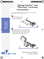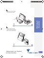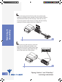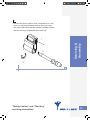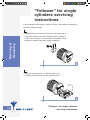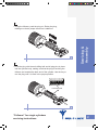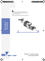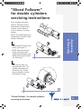
1
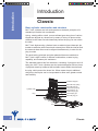
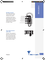
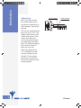
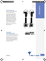
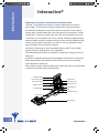
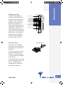
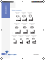
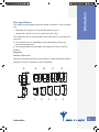
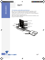
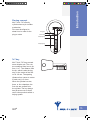
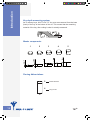
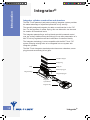
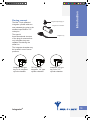
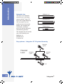
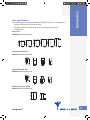
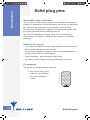
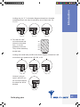
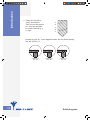
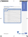
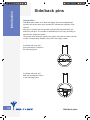
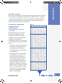
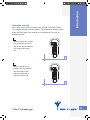
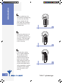
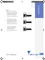
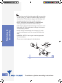
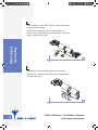
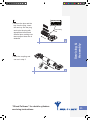
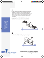
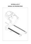
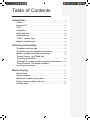
Table of Contents
Introduction............................................................................................4
Classic. .................................................................................................4
Interactive®........................................................................................10
7X7®.....................................................................................................14
Integrator®.........................................................................................18
Solid plug pins.................................................................................22
Side/back pins..................................................................................26
"3-IN-1" cylinder type.....................................................................28
Modular cylinder type....................................................................32
Servicing & Assembly
..............................................................35
Thumbturn cylinder type...............................................................35
Thumbturn cylinder assembly instructions............................37
Modular cylinder assembly instructions. ................................40
"Spring Catcher" and "Filed Key"
servicing instructions...................................................................46
"Follower" for single cylinders servicing instructions.......50
"Sliced Follower" for double cylinders
servicing instructions....................................................................53
Master keying.....................................................................................57
Introduction.......................................................................................57
Design methods...............................................................................60
Work flow of master key system................................................63
Design options profiles and keys..............................................67
General notes. ..................................................................................68
Introduction
Introduction
Classic
Basic cylinder construction and structure
Mul-T-Lock cylinders are built and operate on the basic principles of a
standard pin tumbler lock mechanism.
A plug, rotating within a shell, turns a tail/cam/gear when pins of various
lengths are aligned at a shear line by means of a key. All pins must be
elevated to the shear line simultaneously before the plug can turn within
the shell.
Mul-T-Lock high-security cylinders have an added unique telescopic pin
tumbler mechanism with internal and external pins. Both the internal and
the external shear lines must be aligned simultaneously in order for the
plug to rotate.
This dual-locking principle and other patented features contribute to
Mul-T-Lock’s high number of different combinations, master keying
capability, and extreme pick resistance.
The standard product has five chambers, containing 10 plug pins and 10
body pins. Mul-T-Lock cylinders are also protected against various forms
of physical attack by hardened drill-resistant inserts within the shell and
the plug, which protect the shear line. When master keyed, additional
side pins or back pins can be incorporated to allow even greater control
and flexibility.
Chamber stopper
External body spring
External body pin
Internal body spring
Internal body pin
Master keying pin
Cylinder body
Internal plug pin
External plug pin
Plug
Key
Classic
Introduction
Pinning concept
Mul-T-Lock high security
cylinders have a unique
telescopic pin tumbler
mechanism with internal
and external pins. Both the
internal and the external
shear lines must be aligned
simultaneously in order for
the plug to rotate.
Internal plug pin
External plug pin
Double shear line
Internal body pin
Internal body spring
External body pin
External body spring
Three-dimensional
shear line
The Mul-T-Lock patented
plug has a unique structure.
When the top and bottom
pins, plug and body meet,
a three-dimensional shear
line is formed in an almost
perfect spherical shape.
Classic
Introduction
Classic key
Mul-T-Lock keys contain
five double dimple cuts to
provide two combinations in
each chamber: internal and
external.
Internal combination
External combination
4.8 4.8 4.8 4.8 5.3
The cuts are numbered from
bow to tip, from 1 to 5. The
distance from the tip, which
is also the key stop, to the
center of the fifth cut is
5.3 mm for both Left Hand
(LH) and Right Hand (RH)
keys. The spacing (distance
from center to center of
each cut) is 4.8 mm.
When the cylinder has 4,
3 or 2 chambers, the first
cuts are omitted from the
cylinder. The key always
has all five cuts so that it
can fit other products within
a keying system.
Classic
Introduction
Key hand groups
Mul-T-Lock keys are divided
into two major groups
according to their profiles:
Right Hand (RH) and Left
Hand (LH). To determine
the key hand, hold the key
head with the tip pointing
upwards. If the cuts and/or
milling appear on the right,
this is a Right Hand key.
If the cuts and/or milling
appear on the left, this is a
Left Hand key.
Left Hand
profile
Key depth
measuring system
Right Hand
profile
Y X
As in ordinary keys, Mul-T-Lock
key cuts are measured from the
base (back) of the key to the
bottom of the cut. This means
that the remaining material of
the key, after cutting is what is
actually measured.
Classic
Introduction
Systems components
Solid master
disk # 3
Solid master
disk # 2
External master
disk # 3
External master
disk # 2
ternal master
disk # 3
Internal master
disk # 24
Solid
Solid
master
master
disk
disk
# 3# 1
Solid master
disk # 2
External
Externalmaster
master
disk
disk##13
External master
disk # 2
Internal master
disk # 13
Solid
Solid
master
master
diskdisk
# 3# 1
Solid master
disk # 2
External
Externalmaster
master
disk
disk# #1 3
Internal
Internal master
master Internal
Internal master
master
disk
disk ## 24
disk
disk ## 13
Solid ma
disk #
External master
disk # 2
Internal master
disk # 24
Internal master
disk # 13
Classic
Exte
Inte
Plug pins
Material: Nickel silver.
Structure: Externals are built in a tube shape, to hold the internals within.
Introduction
Pins specification
Diameter: 4 mm for externals; 2 mm for internals.
Patented combines pins (body, driver pins)
Material: Nickel silver for pins, stainless steel for spring
B
A
1
2
D
C
3
4
5
Length: Varies according to product size
Standard
22 mm
19 mm
Classic
Introduction
Interactive®
Interactive cylinder construction and structure
The Mul-T-Lock patented Interactive system raises security levels to
new heights. The Interactive system combines the unique telescopic
pin tumbler mechanism and special features of the Mul-T-Lock Classic
system with a spring-loaded pin in the cylinder plug, to produce a ‘virtual
combination’, which is possible only when the key is inserted in the lock.
To achieve an even higher level of key security, Interactive patented keys
and key blanks provide increased control over key cutting. Additional keys
can be cut only after presentation of a Mul-T-Lock key registration card
and verification of the customer’s identity.
Interactive Technology is retro-compatible with the Mul-T-Lock Classic
system, allowing existing locks to be upgraded.
The standard product has five chambers, containing 10 plug pins and 10
body pins.
Interactive Cylinders are also protected against various forms of physical
attack by hardened drill-resistant inserts within the shell and the plug,
which protect the shear line.
When master keyed, additional side pins or back pins can be incorporated
to allow even greater control and flexibility.
Chamber stopper
External body spring
Cylinder body
Internal body spring
External body pin
Master keying pin
External plug pin
Internal body pin
Internal plug pin
Plug
Interactive plug pin
Interactive pin
Interactive Key
10
Interactive
Introduction
Pinning concept
The Mul-T-Lock patented
Interactive cylinder adds two
new pins to the assortment of
code pins. The new pins are
shorter than the ones used
before in the Classic line.
They actually work above the
‘blank level’, creating a virtual
combination, which can be
raised to the shear line only by
using a Mul-T-Lock Interactive
patented key. The Interactive
chamber may be located in
the first or second chamber,
and can be A0, Z0, or Z1.
Interactive key
Interactive plug pin
Interactive pin
Interactive key
Virtual combination
Internal plug pin
External plug pin
Double shear line
Internal body pin
Internal body spring
External body pin
External body spring
Interactive pin
The keys in the Interactive
series are cut in the same way
as Classic keys, with a slight
difference.
It is only necessary to cut four
positions, because the fifth
position – the Interactive pin
– has already been embedded
at the factory.
The interactive key will contain
one of the following cuts – A0,
Z0, Z1 – which has been
embedded into it during the
manufacturing process.
Interactive
11
Introduction
Systems components
Solid master
disk # 3
Solid master
disk # 2
External master
disk # 3
External master
disk # 2
ternal master
disk # 3
12
Internal master
disk # 24
Solid
Solid
master
master
disk
disk
# 3# 1
Solid master
disk # 2
External
Externalmaster
master
disk
disk##13
External master
disk # 2
Internal master
disk # 13
Solid
Solid
master
master
diskdisk
# 3# 1
Solid master
disk # 2
External
Externalmaster
master
disk
disk# #1 3
Internal
Internal master
master Internal
Internal master
master
disk
disk ## 24
disk
disk ## 13
Solid ma
disk #
External master
disk # 2
Internal master
disk # 24
Internal master
disk # 13
Interactive
Exte
Inte
Two additional pin lengths have been added to the Mul-T-Lock re-keying
kits:
• External pin Z (which is 0.5 mm shorter than the A pin)
Introduction
Pins specification
• Internal pin 0 (which is 0.5 mm shorter than the 1 pin)
The Interactive line of products differs from other Mul-T-Lock products in
two ways:
a. The Interactive pin is embedded in the patented key during the
manufacturing process
b. The spring loaded pin embedded in the plug in the first or second
position
Plug pins
Material: Nickel silver
Structure: Externals are built in a tube shape, to hold the internals within
Diameter: 4 mm for externals; 2 mm for internals
Z
0
Interactive
A
1
B
2
C
3
D
4
5
13
Introduction
7X7®
7x7 cylinder construction and structure
Mul-T-Lock 7X7 is single pin tumbler mechanism, operating on a flat
dimple cut key. The pins and keys are made of nickel silver. A plug,
rotating within a shell, turns a tail or cam when pins of various lengths are
aligned at a shear line by means of a key.
The 7X7 key system standard product comes with seven chambers, seven
plug pins, and seven body pins.
Chamber stopper
Body spring
Body
Mushroom body pin
Body pin
Mushroom
Plug pin
Master keying pin
Plug
Plug pin
Key
14
7X7®
Introduction
Pinning concept
Mul-T-Lock 7X7 security
cylinders have a pin tumbler
mechanism.
Pins must be aligned to
shear lines in order for the
plug to rotate.
Plug pin
Shear line
Body spring
Body spring
7x7 key
Mul-T-Lock 7X7 keys contain
seven dimple cuts. The cuts
are numbered from bow to tip,
from 1 to 7. The distance from
the tip, which is also the key
stop, to the center of the fifth
cut is 4.9 mm. The spacing
(distance from center to center
of each cut) is 3.4 mm.
3.4 3.4 3.4 3.4 3.4 3.4
4.9
When the cylinder has two,
three, or four chambers, the
first cuts are omitted from
the cylinder. The key always
has all seven cuts so that it
can fit other products within a
keying system.
7X7®
15
Introduction
Key depth measuring system
As in ordinary keys, Mul-T-Lock 7X7 key cuts are measured from the base
(back) of the key to the bottom of the cut. This means that the remaining
material of the key, after cutting is what is actually measured.
X
Master components
1
2
3
4
5
Pinning Abbreviations
16
2
Master Disk #2
4
Plug Pin #4
7X7®
Introduction
Pins specification
Plug pins
Material: Brass/nickel silver
1
2
3
4
5
6
Body, driver pins
Material: Brass/nickel silver.
Length: Varies
7X7®
17
Introduction
Integrator®
Integrator cylinder construction and structure
The Mul-T-Lock patented (and patent pending) Integrator system provides
the added advantage of a patented protection to key security.
The specially designed Integrator pin adds a new dimension to the 7X7
line. For the purposes of master keying, this new dimension can be used
for creation of hierarchical levels.
The Integrator patented keys and key blanks provide increased control
over key cutting. Additional keys should only be cut after presentation of a
Mul-T-Lock key registration card and verification of customer identity.
The Integrator technology is retro-compatible with the Mul-T-Lock 7X7
system, allowing existing locks to be integrated into one system with
Integrator cylinders.
The Mul-T-Lock Integrator standard product has seven chambers, seven
plug pins and seven body (driver) pins.
Chamber stopper
Body spring
Body
Body pin
Master keying pin
Integrator Plug
Integrator plug pin
Integrator
Spacial Grove
Integrator Key
18
Integrator®
The Mul-T-Lock patented
Integrator cylinder adds two
new patented plug pins to the
standard specification 7X7
code pins.
The special
three-dimensional structure
of the plug pin ensures that
only Integrator keys are
capable of achieving the
shear line.
Integrator Spacial plug pin
Integrator Oval chamber
Introduction
Pinning concept
Integrator Key
The Integrator chamber may
be located in one of seven
positions.
Integrator “M” type
key cut in Integrator
cylinder chamber
Integrator®
7X7 key cut in
Integrator “M” type
cylinder chamber
Integrator “M” type
key cut in 7X7
cylinder chamber
19
Introduction
Integrator key
M-Master cut
The keys in the Integrator
series are cut in the same
manner as Mul-T-Lock 7X7
keys, with a slight difference.
You only need to cut six
positions since the seventh
position, the Integrator pin
combination, has been
pre-cut in the key during the
manufacturing process.
E-External cut
P-Internal cut
The Integrator key will contain
one of the following cuts:
M-Master cut
E-External cut
P-Internal cut
Key systems – Integrator & 7x7 system hierarchy
Integrator
Type M
Patented
Level
Integrator
Type E
Integrator
Type P
7X7
20
Integrator®
The following pins have been added to the Mul-T-Lock 7x7 re-keying kits:
- Double Launcher pin for M-type keys.
- Single Launcher pin that can be used for internal or external
combination.
Introduction
Pins specification
Plug pins
Material: Brass/nickel silver
1
2
3
4
5
6
Double launcher pin
Material: Brass/nickel silver
Single launcher pin
Material: Brass/nickel silver
Body pins (driver pins)
Material: Brass/nickel silver
Integrator®
21
Introduction
Solid plug pins
Introduction, basic construction
This revolution in master keying concept is only available in telescopic pin
tumblers. An explanation in one brief sentence: we took the “multiple shear
line” away from the plug shear line and moved it into the key side!
By doing this we increased the reliability of a master keyed cylinder, while
the system performance and possibilities goes up!
The core of the approach is “merging” some sets of telescopic pins,
and by doing so we obtained 15 pins that will be added to the Master
keying kits.
Benefit of the concept
• The mechanical reliability of master keyed cylinder is enhanced because
there are now fewer parts in each chamber.
• The security of master key systems to “lockout” of unauthorized keys is
always achieved with the external plug pin.
• Ease of assembly – parts are larger than previously.
• The ability to solve complex cross keying challenges is improved.
Pin categories
The pins can be divided into three categories
a. Pins that will “ride” on the
external cut are identified
by a letter followed by a
(-) sign.
ZABCD-
22
Solid plug pins
Cylinder: CKey: C4
Cylinder: CKey: C3
b. Pins that will “ride”
on both external and
internal, at the same
time – or on the
shallower of the two.
They will be marked by
double letter
Introduction
Looking at a pin “C-” in the below diagram shows that a chamber
containing this pin can only be opened by one of three cuts: C4,
C3, C2.
Cylinder: CKey: C2
ZZ
AA
BB
CC
DD
Looking at the dual letter pin BB in the above diagram, shows that it will
work without any problem with a B3, B2, or C2.
Cylinder: BB
Key: B3
Cylinder: BB
Key: B2
Cylinder: BB
Key: C2
However, trying to
open it with a B1 cut
will not work because
the shear line will be
blocked.
Cylinder: BB
Key: B1
Solid plug pins
23
Introduction
c. These pins are with a
“point” and made to
“ride” only on the internal
cut. They are identified
by a letter followed by a
(+) sign.
Y+
Z+
A+
B+
C+
Looking at a pin “A+” in the diagrams below, the only three opening
cuts are A2, B2, C2.
Cylinder: A+
Key: A2
24
Cylinder: A+
Key: B2
Cylinder: A+
Key: C2
Solid plug pins
Additional combinations are available by introducing the solid master disks
above the solid plug pins.
Chamber
#
Open for keys:
Designation
(Software
report)
1
ZZ
2
AA
3
BB
4
CC
5
DD
6
Z-
7
A-
8
B-
9
C-
10
D-
11
Y+
12
Z+
13
A+
14
B+
15
C+
Z0
Z1
AO
X
X
X
X
A1
A2
B1
X
X
X
B2
B3
C2
X
X
X
C3
C4
D3
X
X
X
D5
X
X
X
X
X
X
X
X
X
X
X
X
X
X
X
X
Solid plug pins
D4
Introduction
Operating chart for solid plug pins
X
X
X
X
X
X
X
X
X
X
X
X
25
Introduction
Side/back pins
Introduction
Side/Back pins enable us to deal with bigger and more sophisticated
systems and at the same time increase the mechanical reliability of the
cylinder.
Any type of cylinder can be specially ordered with plug and body, predrilled for side pins. The number of side/back pins can vary according to
cylinder type length and profile.
The person who builds the master key system will insert the pins and also
cut the corresponding dimples (cuts) on the key edge or back.
A cylinder with only side
pins mechanism is shown in
the following figure:
A cylinder with side and
back pin mechanism shown
in the following figure:
26
Side/back pins
Mul-T-Lock side/back pins operate according to the principle of a blocking
pin inserted into a drilled hole inside the plug. When the key is inserted,
it activates the side/back pin. If the cut is missing, the right side/back pin
combination of the side/back pin will block the plug rotation within the
shell. The side/back pins are passive pins.
Hierarchical relationship
between side pin
combinations
The mathematics behind this is
quite simple:
By introducing one or more side/
back pins in a cylinder, we can
create new differences between
cylinders, on top of those already
existing from the basic key
combination. In Table 1 we describe
all 31 possibilities for side pins. Note
that in:
• 1 through 5, we have always used
1 pins/cuts; in 6 through 15, we
have always used 2 pins/cuts;
• In 16 through 25, we have always
used 3 pins/cuts;
• In 26 through 30, we have always
used 4 pins/cuts. In set 31, we
used all 5 pins/cuts, which can
only be done once! The outcome
is a huge hierarchical scheme
and cross keying that can be very
effectively used to help us meet
master key challenges. The most
effective way is to make use of two
pins in a cylinder, which can split
a system into 10 different groups.
Use of back pins adds a greater
range of combinations.
Side/back pins
Introduction
Operation concept
Table 1
0
1
•
2
•
3
•
4
•
5
6
7
8
9
•
•
•
•
10
11
12
•
•
•
•
13
14
•
•
•
•
15
16
17
18
19
20
•
•
•
•
•
21
22
23
•
•
•
•
•
•
24
25
26
•
•
27
28
29
30
31
•
•
•
•
•
•
•
•
•
•
•
•
•
•
•
•
•
•
•
•
•
•
•
•
•
•
•
•
•
•
•
•
•
•
•
•
•
•
•
•
•
•
•
•
•
•
•
•
•
•
•
27
Introduction
"3-IN-1" cylinder type
Concept
Mul-T-Lock designed the “3-IN-1” cylinder to allow users to easily change
their own key combinations.
It is a simple and speedy process: the user inserts and operates the
next key in a sequence of three keys. The introduction of each new
key invalidates the previous key. The product is packaged with three
key types, color-coded green, yellow and red. The combination change
is possible thanks to an internal pin with the special structure. The
combination change occurs when the round part of the special pin is
sheered off at the pin.
Cylinder structure
The special parts in the "3-IN-1" cylinder are:
• Plug with special holes for the round part
• Two "3-IN-1" internal plug pins
In the chamber where the change takes place, the body pin (driver) and
the external plug pin must be made of steel for increased security.
The cylinder can be keyed simply by dismantling it, inserting new internal
pins and removing the cut-off round parts.
NOTE: There is no option for adding master disks in chambers with the
"3-IN-1" internal pin.
Internal 3-IN-1 pin
External St. steel pin
Available pins:
5-3
4-2
x
3-1
2-0
L
3-IN-1 Plug
St. steel combined pin
28
“3-IN-1” cylinder type
Introduction
Operation concept
Mul-T-Lock allows only two changes per cylinder, for a total of three
key changes starting from the original. The combination change occurs
when the round part of the special pin is sheered off at the pin as
described below:
1
• When a green key is used
in the cylinder, the round
part of the special internal
pin is above the shear
line.
1
2
• When a yellow key is
inserted into the cylinder,
the round part of the
special internal pin is
below the shear line.
2
“3-IN-1” cylinder type
29
Introduction
3
• When a yellow key is in
the cylinder and beginning
to turn for the first time,
the pin rotates with the
plug, while the round part
is cut off and stays in the
cylinder body.
3
4
• When the yellow key is in
the cylinder, continue to
turn and complete the first
time turn. The round part
is pushed into a special
hole in the plug.
4
5
• Cylinder with a yellow
key in regular operation.
The round part of the
special internal pin is
inserted into the special
hole in the 3-IN-1 plug.
Each change is done in a
different chamber, so the
process described above
will be repeated in another
chamber for the change
from the yellow to the
red key.
30
5
“3-IN-1” cylinder type
Examples for the three keys
• The green key will have the
deepest cuts and is the first
key used in the cylinder.
Green key
B3 D5
Introduction
Keys
Green key: A1 D5 B3 A1 D5
• The yellow key will have
one inner pin cut, shallower
than the green key. It is the
second key to be used.
Yellow key
B3 D3
Yellow key: A1 D5 B3 A1 D3
• The red key will have two
inner pin cuts, shallower
than the green key.
Red key
B1 D3
Red key: A1 D5 B1 A1 D3
“3-IN-1” cylinder type
31
Introduction
Modular cylinder type
Concept
Mul-T-Lock Modular cylinder provides you with the ability to build a
cylinder to a desired length. The cylinder is built over a center bar. The
bar has two sides; each side is identified with a number that indicates the
length group to which it belongs.
The Modular Cylinder kit is based on a single box configuration.
Modular cylinder structure
A wide assortment of parts will allow you to build any “side” from a
minimum of 31 mm up to 80 mm. You can build cylinders of 31x31, 33x78
or 35x40 or any other tailored length.
There are two bar types:
• A double-sided cylinder bar, called “x,x” (see Double cylinder structure)
• A single-side cylinder bar, called “x” (see Modular cylinder structure)
See the reference table for the parts required for building the cylinder side
according to the desired length.
32
Modular cylinder type
Introduction
Double cylinder structure
6
5
4
3A
3
2
1
7
8
9
No.
Part
No.
Part
No.
Part
1
Modular cylinder
31, 33, 35
4
Plug adaptor
8
Bar
2
Body spacer
5
Coupling
9
Threaded pin
3
5 mm Plug spacer
6
Cam/gear
3A
7 mm Plug spacer
7
Bar adaptor
Modular cylinder type
33
Introduction
Single cylinder structure
7
6
5
4
3
2
1
8
9
No.
34
Part
No.
Part
No.
Part
1
Modular cylinder
31, 33, 35
4
5 mm Plug spacer
7
Adaptor for single
cylinder
2
Body spacer
5
Cam/gear
8
Bar for single
cylinder
3
Plug adaptor
6
Improved
one-piece
coupling
9
Threaded pin
Modular cylinder type
Servicing & Assembly
Thumbturn cylinder type
Knob types
Servicing &
Assembly
Mul-T-Lock offers a variety of knobs to accommodate different needs or
tastes.
Thumbturn cylinder type
35
Thumbturn structure
Servicing &
Assembly
8
1
2
9
3
4
5
10
7
No.
36
Part
6
No.
Part
No.
Part
1
Thumbturn
5
Pin
9
Spacer for plug
2
Screw
6
Spring
10
Anti-drilling ball
3
Thumbturn plug
7
Back spring
4
Coupling
8
Cam/gear for
thumbturn
Thumbturn cylinder type
Thumbturn cylinder
assembly instructions
1
2
1
3
• Replacing a knob is simply
a matter of unscrewing
one retaining Allen
screw (2).
2
4
3
• Insert parts (4, 5, 6, 7) into
the plug (3).
• NOTE: The length of pin
(5) is 23.5 mm for all
type of cylinders with the
exception of cylinders in
which the "key half" is 35
mm - on these you will
need a 25.5 mm pin.
Servicing &
Assembly
1
5
A
7
Thumbturn cylinder assembly instructions
6
2
37
3
• Position the cam with the wide opening (B) on same side
as the keyway (D). Insert the thumbturn plug all the way
into the body. The thumbturn plug tip (A) should go into
the wide opening side of the cam (B) as shown.
Servicing &
Assembly
• NOTE: Check that the mechanism is integrated and
working properly both with and without the key!
• Hold the plug pushed toward the body until you fix it into
place with new E-clip, otherwise it will pop out because
of the spring’s pressure.
• NOTE: During the assembly of the keyway (D), make
sure that the spacer is with the narrow side toward the
cam.
• GENERAL NOTES: Cam or gear must be appropriate
for the thumbturn.
• There are no modular plugs for the thumbturn.
3
8
C
B
A
D
3
38
Thumbturn cylinder assembly instructions
Unified Plug
The Unified Plug System will help you to reduce your inventory of plugs
by having to keep in stock only the standard plugs and spacers. Another
major benefit is flexibility and availability of products. For example: for a
cylinder side of 60 mm, instead of using a 59.5 mm plug, we can now use
one standard 32.5 mm plug + one 27 mm spacer = 59.5 mm.
Thumbturn cylinder type
Servicing &
Assembly
The main idea behind the concept is to facilitate your logistics. It uses
several standard plugs together with spacers that fit all cylinder sides from
40 mm and up. Cylinders with sides shorter than 40 mm are still produced
with unique plug lengths. Cylinders with sides longer than 40 mm are
produced with standard 32.5 mm plugs, together with one or two spacers
to complete the cylinder length. Naturally, there are different standard
plugs for different key ways: Interactive or 3-IN-1, etc.
39
Modular cylinder
assembly instructions
Modular Assembly concept
Assembly is as easy as 1-2-3. Just decide the length you need, select the
right parts and assemble them. For example, if you want a 31x46 cylinder
you will need:
• One bar type 1, 2 (side 1 for the 31 mm, and side 2 for the 46 mm) and
a bar adaptor.
• For the 31 mm side, you will need body type 31, Plug 31, and nothing
else!
Servicing &
Assembly
• For the 46 mm side, you will need body type 31, Plug 31, 15 mm body
spacer, 15 mm plug spacer and 15 mm plug adaptor.
• Four threaded pins.
NOTE: Bodies and plugs should be ordered separately according to the
profile (key way) that you use, and to the reference table.
In order to replenish the contents of your box, you should use the special
catalogue numbers.
Use the reference table below to determine the parts needed for building
the cylinder side length you need according to the instructions below.
NOTE: For Catalogue Numbers see table 2 at the end of this section.
40
Modular cylinder assembly instructions
Cylinder
Side
Bar
Body
Plug
Body
Spacer
Plug
Spacer
Plug
Adaptor
31
33
35
38
40
41
43
45
46
48
50
51
53
55
56
58
60
61
63
65
66
68
70
71
73
75
76
78
80
1
1
1
1
1
2
2
2
2
2
2
3
3
3
3
3
3
4
4
4
4
4
4
5
5
5
5
5
5
31
33
35
33
35
31
33
35
31
33
35
31
33
35
31
33
35
31
33
35
31
33
35
31
33
35
31
33
35
31.0
32.5
34.5
37.5
39.5
31.0
32.5
34.5
31.0
32.5
34.5
31.0
32.5
34.5
31.0
32.5
34.5
31.0
32.5
34.5
31.0
32.5
34.5
31.0
32.5
34.5
31.0
32.5
34.5
0
0
0
5
5
10
10
10
15
15
15
20
20
20
25
25
25
30
30
30
35
35
35
40
40
40
45
45
45
0
0
Ø7x2
Ø7x5
Ø7x7
Ø5x10
Ø5x10
Ø5x12
Ø5x15
Ø5x15
Ø5x17
Ø5x20
Ø5x20
Ø5x22
Ø5x25
Ø5x25
Ø5x27
Ø5x30
Ø5x30
Ø5x32
Ø5x35
Ø5x35
Ø5x37
Ø5x40
Ø5x40
Ø5x42
Ø5x45
Ø5x45
Ø5x47
0
0
0
0
0
Ø5x10
Ø5x10
Ø5x10
Ø5x15
Ø5x15
Ø5x15
Ø5x20
Ø5x20
Ø5x20
Ø5x25
Ø5x25
Ø5x25
Ø5x30
Ø5x30
Ø5x30
Ø5x35
Ø5x35
Ø5x35
Ø5x40
Ø5x40
Ø5x40
Ø5x45
Ø5x45
Ø5x45
Modular cylinder assembly instructions
Servicing &
Assembly
Table 1: Reference table
41
1
7
8
• Mount the bar adaptor (7)
on the bar (8). Be careful
not to over-spread the bar
adaptor.
1
Servicing &
Assembly
2
8
• Make sure that the bar
adaptor fits correctly.
7
2
3
• If necessary, mount the
required body spacer (2)
onto the cylinder (1).
• NOTE: At this stage, the
cylinder should already
be keyed to the desired
combination
• Slide the two parts together
on the correct bar side until
the holes in the body of the
cylinder are aligned with
holes in the bar.
1
2
3
• NOTE: It is recommended
to start with the longer side
first.
42
Modular cylinder assembly instructions
4
• Screw the two threaded pins (5) using a 1.5 mm
Allen key (provided in the pinning kit). Do not
tighten them all the way. Slide in the plug spacers
and adaptor (3, 4) (If needed), the cam (2) and the
coupling (1).
• NOTE: Threaded pins can only fit one side
5
3
2
1
4
Servicing &
Assembly
4
5
• Mount the appropriate body spacer (2) onto the
cylinder (1). Insert plug spacers and the adaptor
(3, 4). Slide them all on the other side of the bar.
Insert threaded pin (5), confirm that the cylinder is
straight and tighten all the threaded pins.
4
3
2
1
5
5
Modular cylinder assembly instructions
43
Servicing &
Assembly
Table 2: Catalogue Numbers for Replenishment
44
#
Catalogue #
Description
#
Catalogue #
1
Description
84400001
Bar 1
32
88000061
Plug Spacer Ø5x32 mm
2
84400002
Bar 2
33
88000062
Plug Spacer Ø5x35 mm
3
84400003
Bar 3
34
88000063
Plug Spacer Ø5x37 mm
4
84400004
Bar 4
35
88000064
Plug Spacer Ø5x40 mm
5
84400005
Bar 5
36
88000065
Plug Spacer Ø5x42 mm
6
84400008
Threaded Pin
37
88000066
Plug Spacer Ø5x45 mm
7
84400010
Bar Adaptor
38
88000067
Plug Spacer Ø5x47 mm
8
84400011
Bar 1,1
39
81200003
Cam 30°
9
84400012
Bar 1,2
40
80000019
Coupling
10
84400013
Bar 1,3
41
84400130
Body Spacer 5 mm
11
84400014
Bar 1,4
42
84400131
Body Spacer 10 mm
12
84400015
Bar 1,5
43
84400132
Body Spacer 15 mm
13
84400019
Bar 2,2
44
84400133
Body Spacer 20 mm
14
84400020
Bar 2,3
45
84400134
Body Spacer 25 mm
15
84400021
Bar 2,4
46
84400135
Body Spacer 30 mm
16
84400022
Bar 2,5
47
84400136
Body Spacer 35 mm
17
84400023
Bar 3,3
48
84400137
Body Spacer 40 mm
18
84400024
Bar 3,4
49
84400138
Body Spacer 45 mm
19
84400025
Bar 4,4
50
80100613
Plug Adapter Ø5x10 mm
20
80000322
Plug Spacer Ø7x2 mm
51
80100615
Plug Adapter Ø5x15 mm
21
88000018
Plug Spacer Ø7x5 mm
52
80100617
Plug Adapter Ø5x20 mm
22
88000025
Plug Spacer Ø7x7 mm
53
80002027
Plug Adapter Ø5x25 mm
23
88000052
Plug Spacer Ø5x10 mm
54
80002029
Plug Adapter Ø5x30 mm
24
88000053
Plug Spacer Ø5x12 mm
55
80002032
Plug Adapter Ø5x35 mm
25
88000054
Plug Spacer Ø5x15 mm
56
80002034
Body Spacer Ø5x40 mm
26
88000055
Plug Spacer Ø5x17 mm
57
80002036
Body Spacer Ø5x45 mm
27
88000056
Plug Spacer Ø5x20 mm
58
84400057
Allen Key 1.5 mm
28
88000057
Plug Spacer Ø5x22 mm
59
82600260
Emergency Cam
29
88000058
Plug Spacer Ø5x25 mm
60
87602150
STD Cover 5 pin
30
88000059
Plug Spacer Ø5x27 mm
61
84600053
Improved Coupling
31
88000060
Plug Spacer Ø5x30 mm
62
51207080
Single CYL. Adaptor
Modular cylinder assembly instructions
Modular box layout
11, 12, 14, 15
16, 17, 18, 19
58
41
20
21
22
8, 9
37
38
35
36
33
34
31
32
29
30
27
28
25
26
23
24
57
56
55
54
53
52
51
50
49
48
47
46
45
44
43
42
62
61
60
59
39
40
6
7
Modular cylinder assembly instructions
Servicing &
Assembly
1-5, 10, 13
45
"Spring Catcher" and
"Filed Key" servicing
instructions
This method is especially effective for servicing double profile cylinders,
enabling you to work on each side at a time
1
Servicing &
Assembly
• File a matching key to a width
of 6 mm. A 6 mm side jig is
provided in the pinning kit.
6m
6m
m
m
1
2
• Insert the filed key into the cylinder together with the
appropriate spring catcher. Three types of spring
catchers are available: 19 mm, 22 mm and 29 mm.
The spring catcher is provided in the pinning kit.
Push the catcher up to the cylinder body.
2
46
“Spring Catcher” and “Filed Key”
servicing instructions
3
3
4
• Turn the spring catcher
clockwise until the catcher
rests on the cylinder body.
Servicing &
Assembly
• Remove the E-clip, which
holds the plug in place.
4
“Spring Catcher” and “Filed Key”
servicing instructions
47
5
Servicing &
Assembly
• Remove the plug and the filed key from the cylinder body,
making sure that the spring catcher is held in place. Remove
all pins and the filed key from the plug. Insert the new key
into the plug and re-insert the pins to align with the new key,
making sure that a proper shear line is obtained.
5
6
• Remove the key from the plug. Insert the
plug with anti-drilling ball located in the
technical hole into the cylinder body, while
making sure that the plug reaches all the
way to the back end of the cylinder.
Anti-Drilling Ball
6
48
“Spring Catcher” and “Filed Key”
servicing instructions
1
• Remove the spring catcher. Use a screwdriver or a key
tip to turn the plug clockwise until the driver pins pop
into place. Make sure that the cylinder operates properly
with the new key. Reassemble the new E-clip.
Servicing &
Assembly
1
2
3
7
“Spring Catcher” and “Filed Key”
servicing instructions
49
"Follower" for single
cylinders servicing
instructions
In this example we are using a mortise cylinder. This method is suitable for
any kind of single cylinder.
1
Servicing &
Assembly
• Disassemble the two screws mounted on the back end of
the cylinder. Remove the cam. Different types of cams, or
a tail for a rim cylinder, may be fitted to the cylinder. (Pay
attention to spacer mounted in longer cylinders).
1
2
• Using the operating key, turn the plug 180°. (For
cylinders with back pins, turn the plug only 25°!!)
2
50
“Follower” for single cylinders
servicing instructions
3
3
4
Servicing &
Assembly
• Using the follower, push the plug out. Rekey the plug,
making sure that a proper shear line is obtained.
• Push the plug with the anti-drilling ball and all plug pins in place
into the cylinder body, making sure that the plug is touching the
follower and reaches the back end of the cylinder. Use the key to
turn the plug until it is fixed in the proper position.
Anti-Drilling Ball
4
“Follower” for single cylinders
servicing instructions
51
5
• Remove the key while holding the plug in
place. Reassemble the spacer, cam or tail
piece, as necessary.
Servicing &
Assembly
• NOTE: Secure cam screws using “LOCTITE".
5
52
“Follower” for single cylinders
servicing instructions
"Sliced Follower"
for double cylinders
servicing instructions
Since a regular "one piece
follower" cannot be used to
disassemble a double-sided
cylinder, a nice solution is
to use a filed key or a sliced
follower.
Servicing &
Assembly
NOTE: Two operating keys are
needed when using the "sliced
follower" technique.
1
• Remove both E-clips (do not
reuse). (See figure 1).
• NOTE: After removing the
E-clips, the key must be
pulled while holding the plug,
otherwise the plug will come
out with the key.
1
2
• Insert the key from one
side and rotate 180°. (For
cylinders with back pins,
rotate only 25°). Pull the
plug out carefully until the
first chamber is seen.
2
“Sliced Follower” for double cylinders
servicing instructions
53
3
• Do the same for other side, and then take out the cam
along with the coupling.
Servicing &
Assembly
• NOTE: The coupling is the key stopper. After its
removal, you must find the right key position inside the
plug to obtain a shear line.
3
4
• Reinsert one plug into place and remove the key.
• Remove the other plug by pushing the sliced follower
one slice at a time.
4
54
“Sliced Follower” for double cylinders
servicing instructions
5
Anti-Drilling
Ball
5
Servicing &
Assembly
• Remove the pins and the
key from the plug. Insert
the new key into the plug
and re-pin the plug with
appropriate internal and
external pins, making sure
that a proper shear line is
obtained.
6
• Insert the coupling and
cam as in step 3.
6
“Sliced Follower” for double cylinders
servicing instructions
55
7
• Rotate the cam while applying pressure on both plugs
as shown in diagram 7. When one plug snaps into
place, rotate the key to the zero position and take it out.
When removing the key, apply pressure on the plug to
prevent it from coming out. Repeat the same for the
other side.
Servicing &
Assembly
• CAUTION: DO NOT ROTATE KEYS OR PLUGS
BEFORE THE PLUGS ARE FULLY INSERTED.
7
8
• Insert a new E-clips, making sure that the rounded
surface of the E-clips is facing the cylinder body
8
56
“Sliced Follower” for double cylinders
servicing instructions
Master keying
Introduction
This section provides an overview of the Mul-T-Lock master keying
process, and is intended to serve as a reference guide for those who
have completed master key training. It has been designed to assist you
in organizing and implementing a better master key system to meet your
customer’s specific needs.
For every master key challenge - there will be many possible solutions,
but only a few will be both optimal and professional.
Master key systems are a changing and dynamic business; they do not
end when you complete the sale and installation. There will be ongoing
work in cutting additional keys, expanding the system, and maintenance.
It is a long-lasting business and service relationship. A well-designed and
professionally implemented system will provide a constant flow of income
for years to come. On the other hand a poor design and or unprofessional
implementation may damage the company's reputation and cause a flow
of service calls.
Master Keying
Mul-T-Lock believes that professional design and installation of our
systems is essential. To help you accomplish this, we provide professional
back-up and support from the initial design - as it is always better to
"avoid" then "correct" mistakes after system is already made!
Introduction
57
MASTERpiece – Mul-T-Lock software for M.K.S designer
Mul-T-Lock encourages the use of MASTERpiece for creation and design
of any size master key system.
Trying to do it manually will cost you time and you might use an
unauthorized combination. The only approved biting list is embedded
inside MASTERPiece.
The MASTERPiece software makes the master keying process faster,
easier and more efficient. It will automatically produces the necessary
information for the viewing and production of master keying systems,
either specified as a hierarchical system (tree format) or in the matrix
format.
Cross keying can only be addressed in the matrix format.
After gathering all the necessary information about the system and system
characterization, use MASTERpiece to build and design the system.
MASTERpiece enables you to:
• Print a lock scheme of the system for approval by the customer
• Print labels with relevant information to mark packaging.
• Keep records of the system: the key holders, the cylinders/padlocks that
were used and how many were originally requested.
Master Keying
• Full compatibility with Multimanager software.
58
Introduction
Multimanager software
Multimanager software enables keeping track of the keys in a system.
Whenever someone is given a key, it is stored in a database and a receipt
is printed. The receipt shall be signed and stored in an archive.
The program keeps tracks of and can display reports about the number of
keys in stock, the number of keys on loan and how many keys have been
discarded or lost. The program enables handling more than one system.
Documentation
Here you store information such as:
• Who ordered the M.K.S.
• what are the restrictions, Building drawings.
• Special features, etc.
Master Keying
• It will help you understand the reasoning behind the design when asked
to expand the M.K.S.
Introduction
59
Design methods
Hierarchical presentation of master key system
A common name for the hierarchical structure is a "tree" or "flow chart". In
a hierarchical presentation, every node represents a key and cylinder. This
presentation has a rigid structure that will not allow flexibility in current
design, although with a good initial design it shall be easy to expand in the
future. This type of design supports entrance doors.
The logic of this presentation is in enabling several levels of access
authorization; superior levels are authorized to open only related
subordinate levels (e.g. M1 can open M1.1 but cannot open M3.1). There
is no access authorization on the same level (e.g. key M1 cannot open
door M2). The highest level is the grand master key (GM), which can open
all the cylinders in the system. The lowest level includes keys that can
open only a single cylinder.
We use a common method for marking the hierarchy: each dot represents
dropping one level (e.g. M1 is the first level beneath the GM, M1.1 is in
the second level beneath the GM).
GM
Master Keying
M1
60
M2
M1.1 M1.2
M3
M3.1 M3.2
A schematic of a Hierarchical Key System
Design methods
Matrix representation of master key system
This structure allows very flexible design and supports cross keying.
Once the system is installed, changes may involve rekeying of installed
cylinders. It is recommended to include all expansions in the initial design.
Using a matrix chart, each column represents a cylinder and each row
represents a key.
Each X marks an opening, meaning the cylinders that each key can open
(e.g. key K4 opens cylinders C1 and C4)
C1
C2
C3
C4
C5
K1
X
X
X
X
X
K2
X
X
K3
X
K4
X
K5
X
X
X
X
Master Keying
A schematic of a Matrix key system
Design methods
61
Comparison between Hierarchical and Matrix Structures
The table below compares hierarchical (tree) and matrix key systems:
Tree
Matrix
Future expansion
Possible to expand the
system in a relatively
flexible way if you plan
for it in the initial design
You must incorporate the
exact expansions in the
initial design. There is no
easy way of expanding
an existing M.K.S
Cross keying
Limited to common
entrance doors
Supports cross keying
Amount of master disks
Usually one layer of
master disks (Except
entrance doors)
In matrix with cross
keying there are
cylinders loaded with
master disks stacking
Remember: Try to simplify the structure of a system. A simple design will
be easier to maintain and expand over the years, and will last longer.
Always start with the basic hierarchical design and introduce a matrix only
when necessary.
Master Keying
A recent version of Mul-T-Lock's MASTERpiece software facilitates
building a structure that combines the two methods in a way that the
main design of the system is hierarchical but can create sub-matrices for
specific nodes when required.
62
Design methods
Work flow of
master key system
Site survey
Defining the system
System design
System approval
Record Keeping
Repeat Orders
Work flow of master key system
Master Keying
Production
63
Guidelines
Master Keying
When designing a master key system (M.K.S), try to follow the guidelines
below:
64
1. Avoid cross keying.
2. When possible, choose the tree structure rather than a matrix structure.
3. When designing, leave as many constant chambers as possible, but no
less than one chamber.
4. We recommend splitting a large M.K.S. into a few smaller M.K.S.’s.
This will limit the damage in the event of the loss or theft of a master
key. In addition, a smaller M.K.S. can work with fewer master pins and
is much safer.
5. We recommend naming keys and cylinders according to jobs and
functions, rather than by names, because people change more often
than functions or job titles.
6. The cylinder with the lowest M.K. capability is the top barrier for master
keying (e.g. if you have a cylinder with three chambers and two side
pins, you can use only three chambers and two side pins for the
master of the entire master key system).
7. When cutting the chambers, make sure you follow the steps below in
the right order:
A. Cut the middle chamber.
B. Cut the chamber closest to the tip of the key
C. Cut the chamber nearest to the key bow.
NOTE: This does not apply to an Interactive chamber.
8. Due to the sensitivity of master cylinders (multiple shear lines), we
differentiate master cylinders from regular cylinders by using side pins
as added security and clear different from regular keyed products.
Site survey
Before starting to design a M.K.S, it is necessary to understand the nature
of the premises and system, and avoid errors in the type of cylinders or
overlook doors and cylinders.
A site survey is required in order to obtain the full list of cylinders, their type,
and complementary hardware that will be incorporated into this M.K.S.
Work flow of master key system
There are two ways to obtain the list. The first and best way is for the
locksmith who will install the M.K.S. to carry out the survey. The second
way is to obtain a list from the customer.
NOTE: when executing a survey, remember that there are other cylinders,
excluding doors with padlocks and cabinets locks.
When completed, your list should include all cylinder numbers for available
side and back pins, the length and number of chambers, profile, and driver
type (standard or 22).
We recommend creating a blueprint for obtaining them.
Defining the system
This stage is very important and will determine whether the design will be
a tree or a matrix.
The role of the locksmith is to advise and guide the client to the best and
safest M.K.S. for his needs. To do this, he must perform the following
steps:
• Establish the access structure - which keys will open which locks.
• Future developments affecting the access must be discussed with the
client and future expansion of the system should be jointly formulated.
• When designing the system, remember to include in your plans
expansion over the entire lifespan of the system.
• Decide on the visible markings on cylinders and keys. It is critical to
mark the cylinders and keys for subsequent management of the M.K.S.
• Be careful not to make it too obvious. Do not leave identifying details
on the keys, such as the company name, so they cannot be traced if
lost or stolen. Use sequential numbers or any other non-distinguishable
methods.
• For a tree, our default markings are GM, M1, M1.1, and so forth. If you
want customized marking, make it simple.
Work flow of master key system
Master Keying
• Always try to achieve the maximum possible capability without
overloading the system with master pins for cylinders that will never be
installed.
65
• Decide how many keys will be provided with each cylinder, packaging,
and package markings.
• Finally, decide the contact person with whom you will work.
System approval
We strongly recommended that the final design, including the system
layout and combinations, should be sent to the customer for their written
approval.
Production
Print cylinder pin chart and key combinations from the MASTERpiece.
Assemble the cylinders and cut the keys according to output. Mark
cylinder and keys as agreed with the client.
Insert each cylinder into a separate nylon bag with the appropriate label
(printed with MASTERpiece). Repeat the process for the keys.
Master Keying
Record keeping
66
We recommend saving a MASTERpiece file by using a system number.
Make sure that there is a back-up file and keep it updated. Keep a hard
copy as well, including all relevant documents. It is essential to keep
track of what was actually installed on the site, as this will give you better
control of changes and will protect you from allegations of malpractice
caused by someone else making changes in the system. All this data is
confidential and sensitive - you must secure it and restrict access to the
hard copy and computer archive.
Repeat orders
Refer to production and updated records.
Changes in design with regard to the limitation of the existing system are
carried out in the same way as the first stage in the initial design.
Work flow of master key system
System design
Determine the system number and GM combination using GM combination
package. The idea is to prevent random repetition of GM combinations
for different M.K.S. There are different kinds of GM combination packages
for each profile (classic and Interactive® for a total of seven types).
GM combination package contain a list of ten different combinations,
each one identified by unique identification number. Each combination is
intended for the production of one unique master key system (see sample
list). Ten cards, each stamped with an identification number that appears
in the herein list. This card is given to the end user so that the locksmith
can produce extra keys, change combinations, service the system, etc.
Mul-T-Lock works only with system numbers, making it essential to keep
the card for future dealings with us.
Classic–Master key combination
Page No 03781
Sequence no:1
Mul-T-Lock
Mul-T-Lock
Mul-T-Lock
Mul-T-Lock
Mul-T-Lock
Mul-T-Lock
Mul-T-Lock
Mul-T-Lock
®
®
®
®
®
®
®
®
Mul-T-Lock
Mul-T-Lock
Mul-T-Lock
Mul-T-Lock
Mul-T-Lock
Mul-T-Lock
Mul-T-Lock
Mul-T-Lock
®
®
®
®
®
®
Work flow of master key system
®
®
Mul-T-Lock
Mul-T-Lock
Mul-T-Lock
Mul-T-Lock
Mul-T-Lock
Mul-T-Lock
Mul-T-Lock
Mul-T-Lock
®
®
®
®
®
®
Master Keying
GM combination
System number
®
®
67
Design options
profiles and keys
LH Keyways for master keying
In addition to our extensive master capability, Mul-T-Lock offers
hierarchical structure of keyways (multi-profile structures).
The multiplex system consists of master keyway 99 and seven subkeyways.
99
13
15
23
25
33
35
37
It is essential to use left hand (LH) keyways for master keying.
Master Keying
Using a double sided key
68
A double-sided key in the master key system may be used to create
greater system manipulation and flexibility. By cutting each side of the key
differently, each side can become a different key. To distinguish one side
from the other, there is colored insert on one side. One way of using a
double-sided key is to create a GM for the M.K.S. with two combinations
that can have only two cylinders (e.g. home and office), or big systems
that are keyed alike. These systems do not use master disks, and are
therefore more secure and more durable. They may be produced using
keys and cylinders from stock. Central M.K.S. uses double-sided keys in
the following two ways:
• A double-sided GM for two different M.K.S. on one key. This option
allows us to create a larger M.K.S., bearing in mind that we have to
ensure that the cylinder on one side will not be opened accidentally by
the other.
• The recommend option: use one side for the M.K.S. and the other
with an uncut cylinder for the entrance door. Entrance doors are the
weakest point in any M.K.S. This cylinder works much harder than all
other cylinders in the system, because all users go through this door.
For entrance doors, use cylinders with multiple master disks, as these
cylinders are more vulnerable than other cylinders. Using a double-sided
key for the entrance door allows the use of a non “M.K.S. cylinder”. The
result is a significant improvement in the lifespan of the cylinder.
Design options profiles and keys
General notes
NOTE: Make sure to mount the E-clip so that its rounded edges face the
cylinder body and confirm that it is properly aligned with the plug groove.
The E-clip should be replaced and not reassembled.
After re-assembly, make sure that the cylinder operates properly with the
new key on both sides.
Lubricate the cylinder using only Mul-T-Lock “lubricating spray”. Do not
use graphite or WD-40.
NOTE: Do not apply torque above 4 N/M for fixing cylinder screws!
Do not use a Power Driver to secure cylinder screws!
When assembling plugs with master key disks, you must make sure that
all the master pins are inside the plug. There are two options:
• Use a key with the deepest cuts possible in the system, in all the
chambers.
If such a key does not exist, go to the next option.
Master Keying
• Remove the plug without a follower, take out all the master pins that
were inside the body, and reload the body.
General notes
69
NOTES