1
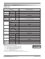
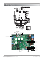
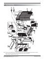
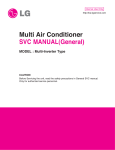
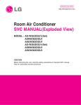
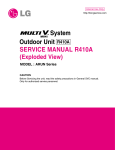
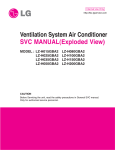
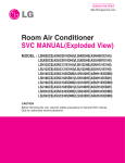
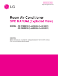
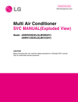
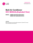
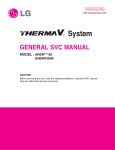
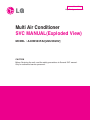
Internal Use Only
http://biz.lgservice.com
Multi Air Conditioner
SVC MANUAL(Exploded View)
MODEL : A4UW363FA2[LMU369HV]
CAUTION
Before Servicing the unit, read the safety precautions in General SVC manual.
Only for authorized service personnel.
1. Specification
Outdoor Unit
Outdoor Unit
Capacity(*)
Power Input
(Min.~Rated~ Max.)
Running Current
Cooling
Heating
Cooling
Heating
Cooling/Heating
Starting Current
Power Supply
Power Supply Cable (Outdoor)
Transmission Cable (Outdoor to Indoor unit )
Dimensions
WxHxD
A4UW363FA2(LMU369HV)
Btu/h Class
kW
kW
A
A
A
Ø / V / Hz
No.x AWG
No.x AWG
34,000
0.77~2.72~ 3.92
1.12~3.58~4.1
3.3~11.8~17.0
4.9~15.5~17.8
1/208 - 230/60
3 × 12
4 x 18 (Including Earth)
900 x 1,165 x 370
(35 7/16 x 45 7/8 x 14 9/16)
95(209.4)
4
Twin-Rotary
GPT425DBA
BLDC
1300
FVC68D
3,500(123.46)
R410A
EEV
(2R x 26C x 17) x 2
7(0.276)
Reversing cycle
Direct (DC)
Side
60(2,118) x 2EA
57
6.35(1/4) × 4EA
9.52(3/8) × 4EA
75(246.1)
25(82.0)
30(123.0)
15(49.2)
7.5(24.6)
-10 ~ 46 (14~114.8)
-15 ~ 24 (5~75.2)
mm(inch)
Net Weight
kg(lbs)
Max. Number of Connectable Indoor Units
Compressor
Type
Qty x Model
Motor type
Oil charge volume
cc
Oil Type
Refrigerant
Cycle A Charge (at 7.5m)
g(oz)
Cycle B Charge (at 7.5m)
g(oz)
Type
Control
Heat Exchanger
(Rows x Column x FPI) x No.
Coil tube dia.
mm(inch)
Defrosting Method
Fan motor
Capacitor
μF/Vac
Drive
Discharge Direction(Side/Top)
Air Flow Rate x No. of Fan CMM(CFM)
Sound Level(H)
Sound Pressure
dB(A)+3
Piping Connections
Liquid(Cycle A)
mm(inch)
Gas(Cycle A)
mm(inch)
Liquid(Cycle B)
mm(inch)
Gas(Cycle B)
mm(inch)
Piping length spec.
Max. total piping
m(ft.)
Max. OD~ID piping
m(ft.)
Piping length(no add'l refrigerant)
m(ft.)
Max. Elevation
Outdoor Unit~Indoor Unit
m(ft.)
Difference
Indoor Unit~Indoor Unit
m(ft.)
Operation Range
Cooling
°C(°F)
(Outdoor)
Heating
°C(°F)
Note:
1. Capacities are based on the following conditions:
Cooling: - Indoor Temperature 27°C(80.6°F) DB/19°C(66.2°F) WB
- Outdoor Temperature 35°C(95°F) DB/24°C(75.2°F) WB
Heating: - Indoor Temperature 20°C(68°F) DB/15°C(59°F) WB
- Outdoor Temperature 7°C(44.6°F) DB/6°C(42.8°F) WB
Piping Length - Interconnecting Piping Length 7.5m
- Level Difference of Zero
2. Wiring cable size must comply with the applicable local and national code.
3. The specification may be subject to change without prior notice for purpose of improvement.
Copyright ©2008 LG Electronics. Inc. All right reserved.
Only for training and service purposes
-2-
Conversion Formula
kW = Btu/h x 0.0002931
cfm = CMM x 35.3
LGE Internal Use Only
2. Function Table
Category
A4UW363FA2
[LMU369HV]
O
X
X
X
O
O
O
X
O
O
O
PQNUD1S00
PMNFP14A0
O
-
Function
Defrost / Deicing
High Pressure Switch
Low Pressure Switch
Phase protection
Reliability
Restart Delay (3-minutes)
Self Diagnosis
Soft Start
Test Function
Auto operation(Artificial intelligence)
Convenience
Auto Restart Operation
Central control(LGAP)
CAC Network
PDI(Power Distribution Indicator)
Function
PI485
Special function kit Low ambient operation
Others
Thermistor
Note :
• O: Applied, • X: Not applied, • - : No relation,
• Option: Model name & price are different according to options, and assembled in factory with main unit.
• Accessory: Installed at field, ordered and purchased separately by the corresponding model name, supplied with separate package.
Copyright ©2008 LG Electronics. Inc. All right reserved.
Only for training and service purposes
-3-
LGE Internal Use Only
3. Piping Diagrams
Outdoor Unit
Accumulator
Reversing
Valve
Field piping
Gas(Ø3/8")
Room D
Room C
Room B
Room A
Th1
Oil Separator
S/V
Th3
Th4
Heat
Exchanger
Main service
Valve(Gas)
Field piping
Liquid(Ø1/4")
EEV-D
Room D
Room C
Room B
Room A
EEV-C
Compressor
EEV-B
EEV-A
Th2
Main service
Valve(Liquid)
REFRIGERANT FLOW
COOLING
HEATING
LOC.
Description
PCB Connector
Th1
Thermistor for outdoor air temperature
CN_TH2
Th2
Thermistor for condensing temperature
CN_TH2
Th3
Thermistor for discharge pipe temperature
CN_TH3
Th4
Thermistor for suction pipe temperature
CN_TH3
S/V
Solenoid Valve for Hot Gas/Oil Separator
CN_H/GAS
/CN_OIL/S
L/P
Low Pressure Switch
CN_PRESS
Copyright ©2008 LG Electronics. Inc. All right reserved.
Only for training and service purposes
-4-
LGE Internal Use Only
4. Wiring Diagrams
CN_H/GAS
CN_OIL/S
CN_PFC_IN
CN_4WAY
CN_PFC_OUT
CN_TH3
CN_TH2
CN_EEV4
CN_EEV3
CN_EEV1
CN_EEV2
CN_MOTOR2
CN_MOTOR1
Copyright ©2008 LG Electronics. Inc. All right reserved.
Only for training and service purposes
-5-
CN_COM
LGE Internal Use Only
552203B
552203A
W49810
661400D
661400C
152503
430411
447910
435511
237202
437211
435301
559010
137213
546810
546810
349600
435512
661400B
W4810
554160
550140
W6631
552114
552200
W4986A
W4986B
552117
561410B
552204
W6640C
268711
649950
554031A
561410A
552116
W6640A
W6640B
552202
661400A
554031B
437212
352112
552113
263230D
263230E
5. Exploded View
Note) * Please ensure GCSC since the replacement parts may be changed depending upon the buyer's request.
Please check the correct parts in View RPL(Replacement Part List) on GCSC.
(GCSC Website http://biz.Lgservice.com,)
Copyright ©2008 LG Electronics. Inc. All right reserved.
Only for training and service purposes
-6-
LGE Internal Use Only
P/NO : MFL63721203
June, 2010