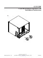
1
CCF/CHF
Cased Horizontal Evaporator Coil
Installation Instructions
R
C
October 2002 Rev. 4 (1)
R
Goodman Company, L.P.
1810 Wilson Parkway • Fayetteville, Tennessee 37334
www.amana-hac.com
10618412
Table of Contents
General ...................................................................................................................................... 2
Shipping and Handling ................................................................................................................................... 2
Location Requirements .................................................................................................................................. 2
Product Application ........................................................................................................................................ 2
Installation Instructions ........................................................................................................... 3
PreInstallation Requirements ........................................................................................................................ 3
Installation ....................................................................................................................................................... 3
Furnace ............................................................................................................................................................................................... 3
Blower Section .................................................................................................................................................................................... 4
Refrigerant Piping .................................................................................................................... 5
Job Site Brazing .................................................................................................................................................... 5
Refrigerant Charge ................................................................................................................................................ 5
Restrictor Orifice ................................................................................................................................................... 5
Refrigerant Piping .................................................................................................................... 6
TXV Kit Installation (CCF Only) ........................................................................................................................... 6
Refrigerant Pipe Connections .............................................................................................................................. 6
Drain Connection ..................................................................................................................... 7
Maintenance.............................................................................................................................. 7
Condensate System Maintenance (Qualified Servicer Only) ............................................................................. 7
Air Filters ............................................................................................................................................................... 7
Filter Maintenance ................................................................................................................................................. 7
Coil Cleaning ......................................................................................................................................................... 7
• Units must be installed in accordance with Regulations of the National
Fire Protection Association and applicable local codes. Where local
regulations are at a variance with instructions, installer should adhere
to local codes.
• Before connecting tubing, read the outdoor unit installation manual.
Pay particular attention to all safety precautions.
RECOGNIZE THIS SYMBOL AS A SAFETY PRECAUTION.
ATTENTION INSTALLING PERSONNEL
As a professional installer you have an obligation
to know the product better than the customer. This
includes all safety precautions and related items.
Remember, it is your responsibility to install the
product safely and to know it well enough to be
able to instruct a customer in its safe use.
Prior to actual installation, thoroughly familiarize
yourself with this Instruction Manual. Pay special
attention to all safety warnings. Often during
installation or repair it is possible to place yourself
in a position which is more hazardous than when
the unit is in operation.
Safety is a matter of common sense...a matter of
thinking before acting. Most dealers have a list of
specific good safety practices...follow them.
The precautions listed in this Installation Manual
are intended as supplemental to existing practices.
However, if there is a direct conflict between existing
practices and the content of this manual, the
precautions listed here take precedence.
2
General
Product Application
These horizontal coils can be installed on a furnace or air handling unit. They are specifically designed to “match up”
with Amana condensing units and heat pumps to provide high efficiency heating or cooling. These coils are suitable for
either attic or crawl space installations. Its bi-directional airflow provides greater flexibility in horizontal left and horizontal
right applications. Non-bleed thermal expansion valve kits can be field installed on CCF coils (See “Specification Sheet”).
Thermal Expansion Valves (TXV) and flow restrictors give accurate refrigerant control and provide reliable operation
over a wide range of conditions. To avoid poor operation or equipment damage, any single-phase reciprocating
compressor used with an expansion valve coil must include hard start components. Ensure that the outdoor unit has
hard start components or install a hard-start kit. See the outdoor unit “Specification Sheet” for the proper kit number.
NOTE: It may be necessary to change the factory-installed expansion valve on a CHF**TCC coil in order to match the
outdoor unit capacity.
CHF**TCC
Required TXV Kit
Outdoor Capacity
Coil Size
CHF18TCC
TXV01A
1 1/2 to 2 tons
CHF24TCC
CHF30TCC
CHF36TCC
CHF42TCC
CHF48TCC
CHF60TCC
TXV02A
2 1/2 to 3 tons
TXV03A
3 1/2 to 5 tons
For service operating conditions, refer to the “Specification Sheet” from the matching condensing unit.
• Only allow qualified, experienced technicians to install or service this unit.
Shipping and Handling
All units are securely packed in shipping containers tested according to International Safe Transit Association
specifications. Upon receipt of the coil assembly, inspect for any damage which may have occurred in transit. If damage
is obvious, it should be noted on the carrier’s freight bill for inspection and initiation for settlement of claim be made at once.
Units are usually shipped F.O.B. factory, and it is the consignee’s responsibility to file damage claims. If no damage is
found, shipping material should be removed and properly discarded.
Location Requirements
The coil can be installed with zero clearance to combustible materials. Adequate room must be provided for servicing,
routing of refrigerant lines, and routing of drain lines including a drain trap. Do not locate the unit directly on the ground
or in an area that may become wet. If installed over a finished ceiling or living space, a secondary drain pan (with drain
line) should be positioned under the entire unit.
3
Installation Instructions
PreInstallation Requirements
Rods
COIL SIZING
Coils should be sized prior to installation based on recommended matches to the outdoor unit. Refer to sales literature and the ARI directory. Install unit in accordance with
Regulations of the National Fire Protection Association
and applicable local codes. Where there are variances
with the national code, adhere to local codes.
Air Flow
Furnace
The capacity of the cooling or heating system is obtained
from the published ratings.
Support
Isolation Pads
Figure 1
NOTES:
•
For TXV installation, select the TXV kit specified on
the condensing unit specification sheet or sales
literature.
•
For orifice installation, select the orifice size specified by the outdoor unit.
Coil Section
Blower Section
Air Flow
COIL CLEANING
To obtain optimum performance on initial start-up, the coil
assembly must be cleaned with a mild dishwashing detergent or coil cleaner to remove any manufacturing oil
residue, dirt, or other foreign substances from the coil
finned surfaces.
Figure 2
COIL ATTACHMENT
Installation
Furnace
When attaching the coil to either a gas or oil furnace, mount
the coil at the supply air end of the furnace (unless the
furnace manufacturer instructs otherwise). Ensure the
drain pan is down. For proper drainage, the coil must be
level or pitched toward the drain connections. If necessary,
shim under the furnace so the furnace and coil casing will
both be level or pitched toward the drain.
The Cased Horizontal Evaporator Coil can be installed
either suspended (Figure 1) or directly on a surface (Figure
2). In either installation, ensure the coil bottom is fully
supported and resting on rubber isolation pads. These
pads will minimize vibration and sound transmission to the
structure.
CAUTION
Horizontal Left Applications
In this application, the opening in the right side of the
casing mates with the supply side flanges on Amana Air
Command™ furnaces. Ensure the furnace flanges are
turned up.
It is the installer’s responsibility to ensure
the coil is properly supported.
Horizontal Right Applications
In this application, if you wish to create more surface area
for attachment of duct work (Figure 3), turn the front panel
180°.
4
Installation Instructions
3. Lift up the pan mount and slide the bottom duct flange
underneath onto the casing flange (Figure 3).
Coil Casing
Coil Casing
Wide Side
Flip 180º
Thin Side
Pan Mount
Front Panel
Figure 3
Duct Flange
If the furnace and coil are not similar in depth and width, a
transition will have to be field-supplied. Center the furnace
and coil openings relative to each other. Fasten the
assembly securely, and seal as necessary to reduce air
leakage. Do not allow screws to penetrate the coil drain
pan or tubing.
Figure 3
4. Lower pan mount. Secure duct flange and pan mount
to the coil casing using the screws removed in step 2.
Duct Flange Attachment
The duct flanges for the return air side are shipped unattached. If necessary, carefully drive the flanges into place
using a mallet. In an horizontal left application use three
(3) flanges; in an horizontal right application use four (4).
Blower Section
The cased coil is designed to mate flush with a BBA/BBC
blower section on either horizontal right or horizontal left
applications.
1. Slide the top and side duct flanges onto the casing
flange.
Note: Left side duct flange is not used in horizontal left
installations.
2. Remove the screws attaching the pan mount to the
coil casing.
The coil section must be mounted “upstream”
(return air side) of the blower section. Use three adapter
plates to connect the coil and blower section together, one
on each side and one on the back. NOTE: Two adapter
plates are shipped with the blower section and one with the
coil section. Refer to Duct Flange Attachment section to
complete installation.
5
Refrigerant Piping
Job Site Brazing
Restrictor Orifice
See companion outdoor condensing unit instructions for
recommendations on field piping of interconnecting refrigerant lines.
REMOVAL
Line sizes for runs of fifty feet or less should be based on
the line diameters of the outdoor unit. For lengths greater
than 50 feet, refer to the product service manual. A field
provided adapter may be necessary depending on line
size used and connection size.
2. Remove and discard the factory-installed restrictor.
1. Disassemble the distributor flow control assembly by
holding distributor body with a wrench and turning
the brass hex nut.
NOTE: If the restrictor does not drop out of the distributor body when disassembled, remove by using
an orifice extractor.
Refrigerant Charge
3. Remove existing teflon washer if present and discard.
The coil is shipped without refrigerant. The coil has a
holding charge of dry nitrogen to keep it dry and to keep
foreign substances from contaminating the assembly.
See instructions provided with outdoor unit for refrigerant
charging information.
REPLACEMENT
1. When required, install new teflon seal as shown in
Figure 3.
A distributor flow control assembly is shipped with this coil;
however, certain conditions may require that the orifice in
the assembly be replaced. The outdoor unit will determine
if the orifice will need to be replaced with a properly sized
one in order to run efficiently. Amana outdoor units are
shipped with the properly sized orifices. Restrictor orifices
are also available in accessory kits.
2. Insert new restrictor fully into the distributor body
with smaller end towards the indoor coil as shown in
Figure 3. Ensure the restrictor stays inserted in body
before connecting mating half.
To keep your Amana unit warranty in effect, the Amana unit
MUST be matched up with the appropriate TXV kit if
required. Refer to the outdoor unit Specification Sheet for
the correct TXV kit needed to properly run the unit efficiently.
4. Tighten assembly to 10-12 ft/lbs of torque. Use a
suitable torque wrench with properly sized open end
wrench adapter. Use a backup wrench to prevent
twisting of distributor tubes when applying torque.
Care must be taken not to misshape the distributor
body.
3. Thread assembly halves together by hand to insure
proper mating of threads. Hand tighten until snug.
NOTE: If a torque wrench is not available, mark a
line on each part. Then tighten an additional 1/6 turn
(or 1 hex flat)
CAUTION
Excessive torque can cause orifices to
stick. Use the proper torque settings when
tightening orifices.
Distributor Tubes
Distributor Body
Restrictor
Teflon® Seal
X XX
O-Ring
3/8" Sweat
Closure
Fitting
Orifice Size
Restrictor Bullet Nose
(O-Ring Seal Side)
to face Distributor Tubes
13/16" Brass
Hex Nut
Figure 4
6
Refrigerant Piping
TXV Kit Installation (CCF Only)
Refrigerant Pipe Connections
Install this kit on CCF coils to increase system efficiency.
1. Remove plugs in pipe outlets on coil.
1. Insert the outlet of the TXV (female fitting) into the
distributor body. Connect the assembly halves together and tighten by hand. Install the inlet tube
onto the inlet of the TXV (male fitting). Hand tighten
the joint.
2. Cut field tubing off squarely and cut to correct length,
deburr.
2. Remove the cap from the Schraeder valve on the
vapor manifold. Without kinking, attach the TXV
equalizer line to the Schraeder valve. Hand tighten
the nut onto the Schraeder valve.
4. Insert fully into the swage provided.
3. Inspect tubing ends. Tubing must be round and
with- out nicks or dents on tubing surface which is to
be brazed to the unit.
5. Braze the tubing.
NOTE: This is a copper to copper joint, use an appropriate
brazing alloy (2% minimum silver).
3. Tighten the equalizer connection to 10-12 ft/lbs of
torque.
CAUTION
CAUTION
If the unit has a thermal expansion valve
either wrap the expansion valve and
sensing bulb with a wet rag, use a thermal
block or a similar heat dissipating material
to prevent damage to the expansion valve.
Do not reuse old washers, system leak
could occur.
4. Tighten the TXV connections to 15-30 ft/lbs of
torque. Use a suitable torque wrench with properly
sized open end wrench adapter. Use a backup
wrench to prevent twisting of distributor tubes when
applying torque.
6. For proper leak test, evacuation, and charging procedures, see the outdoor unit installation manual.
Leak testing is to be done on line set only; therefore,
do NOT use refrigerant from condensing unit for
testing leaks or you may need to evacuate system if
a leak is detected.
NOTE: If a torque wrench is not available, mark a line
on each part. Then tighten an additional 1/6 turn (or 1 hex
flat).
WARNING
To avoid the risk of fire or explosion, never
use oxygen, high pressure air or flammable
gases for leak testing a refrigerant system.
7
Drain Connection
The drain connection on the coil requires a full size drain as it exists on the unit. The connection is 3/4" ID FPT. The drain
line must contain a trap. If a proper trap is not present, the drain pan could overflow.
NOTE: To avoid double trapping, and possibly an overflowing drain pan, it is not recommended to use soft plastic drain
lines.
If used, the auxiliary drain must be piped separately from the main drain connection and must contain a trap located below
the bottom of the drain pan.
The auxiliary drain connection is 3/4" ID FPT.
1" MIN.
PITCH
TOWARDS
DRAIN
CONDENSATE
DRAIN CONN.
CONNECT DRAIN
SAME SIZE AS ON
UNIT OR LARGER
TRAP
Figure 5
Maintenance
Condensate System Maintenance
(Qualified Servicer Only)
Filter Maintenance
IMPORTANT: To avoid the risk of poor performance,
severe equipment damage, and/or loss of warranty coverage, do not operate the coil without clean filter(s) in place.
As it cools the air, the coil can produce condensation. This
water must be drained away properly. At least once a year,
a qualified servicer should inspect the drain pan(s) and
drain line(s) to confirm that the condensate will drain
properly. Cleaning or adjustment may be required at this
time.
Filter(s) should be inspected every month, and cleaned or
replaced when necessary. It is the user’s responsibility to
keep the filters clean. Dirty filters are the most common
cause of poor heating or cooling performance.
Your air filter(s) could be located in “filter grilles” in your
ceiling or walls, or in the blower coil or furnace. The installer
of your coil can tell you where your filter(s) are, and how to
clean or replace them. If you cannot reach your installer,
call another qualified servicer.
Air Filters
Air Filter(s) must be supplied by the installer. All of the
return air must be filtered before it enters the coil. If this coil
is installed without filter(s), poor performance, severe
equipment damage, and/or loss of warranty coverage
could result. These problems could affect both the indoor
unit and the outdoor unit.
Coil Cleaning
An annual air conditioning checkup including a good coil
cleaning, leak check and system pressure check will help
keep the system operating at peak efficiency. These coil
cleanings should be performed by a qualified servicer.
As one option, the installer can supply filter grille(s) in the
walls and/or ceiling return air duct terminations. If this is
done, a filter at the unit will not be required.
If possible, discuss filter location and maintenance with the
homeowner before leaving the job.
®
is a trademark of Maytag Worldwide N.V. and is used under license to Goodman
Company, L.P. All rights reserved.
8