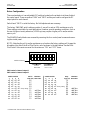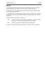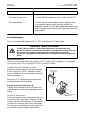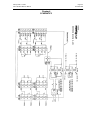
1
ITW Dynatec
An Illinois Tool Works Company
31 Volunteer Drive
Hendersonville, TN 37075 USA
Telephone 615.824.3634
FAX 615.264.5222
OPERATIONS & SERVICE MANUAL #50-07
Revised 12/06
Adhesive Application Solutions · ISO 9001 Certified
OPERATIONS AND SERVICE MANUAL
ILD-2 ELECTRIC VALVE DRIVER
PN 106096 ILD-2 Driver, 120 VAC
PN 106097 ILD-2 Driver, 240 VAC
Software V. A02
IMPORTANT ! - READ ALL INSTRUCTIONS BEFORE OPERATING THIS EQUIPMENT
It is the customer’s responsibility to have all operators and service personnel read and understand
this information. Contact your ITW Dynatec customer service representative for additional copies.
NOTICE! Please be sure to include the serial number of your application system
each time you order replacement parts and/or supplies. This will enable us to
send you the correct items that you need.
ITW Dynatec Service Parts Direct Dial: 1-800-538-9540
ITW Dynatec Technical Service Direct Dial: 1-800-654-6711
Page ii
Revised 8/99
ITW Dynatec c. 1999
ILD-2 DRIVER Manual #50-07
TABLE OF CONTENTS
Chapter - Page #
Chapter 1 Description & Specifications
Description . . . . . . . . . . . . . . . . . . . . . . . . . . . . . . . . . . . . . . . . . . . . . . . . . . . . . . . . . . . . . . . . . . . . . . . . . . . . . . .
Theory of Operation . . . . . . . . . . . . . . . . . . . . . . . . . . . . . . . . . . . . . . . . . . . . . . . . . . . . . . . . . . . . . . . . . . . . . . . .
Specifications . . . . . . . . . . . . . . . . . . . . . . . . . . . . . . . . . . . . . . . . . . . . . . . . . . . . . . . . . . . . . . . . . . . . . . . . . . . . .
Dimensions . . . . . . . . . . . . . . . . . . . . . . . . . . . . . . . . . . . . . . . . . . . . . . . . . . . . . . . . . . . . . . . . . . . . . . . . . . . . . . .
1-1
1-2
1-3
1-4
Chapter 2 Installation & Operation
Installation . . . . . . . . . . . . . . . . . . . . . . . . . . . . . . . . . . . . . . . . . . . . . . . . . . . . . . . . . . . . . . . . . . . . . . . . . . . . . . .
Control Panel . . . . . . . . . . . . . . . . . . . . . . . . . . . . . . . . . . . . . . . . . . . . . . . . . . . . . . . . . . . . . . . . . . . . . . . . . . . . .
Bottom of Driver Enclosure . . . . . . . . . . . . . . . . . . . . . . . . . . . . . . . . . . . . . . . . . . . . . . . . . . . . . . . . . . . . . . . . .
Component Layout . . . . . . . . . . . . . . . . . . . . . . . . . . . . . . . . . . . . . . . . . . . . . . . . . . . . . . . . . . . . . . . . . . . . . . . . .
Driver Configuration . . . . . . . . . . . . . . . . . . . . . . . . . . . . . . . . . . . . . . . . . . . . . . . . . . . . . . . . . . . . . . . . . . . . . . .
Operation . . . . . . . . . . . . . . . . . . . . . . . . . . . . . . . . . . . . . . . . . . . . . . . . . . . . . . . . . . . . . . . . . . . . . . . . . . . . . . . .
2-1
2-2
2-2
2-3
2-4
2-5
Chapter 3 Troubleshooting
In General . . . . . . . . . . . . . . . . . . . . . . . . . . . . . . . . . . . . . . . . . . . . . . . . . . . . . . . . . . . . . . . . . . . . . . . . . . . . . . . . 3-1
Troubleshooting Guide . . . . . . . . . . . . . . . . . . . . . . . . . . . . . . . . . . . . . . . . . . . . . . . . . . . . . . . . . . . . . . . . . . . . . . 3-1
Parts Replacement . . . . . . . . . . . . . . . . . . . . . . . . . . . . . . . . . . . . . . . . . . . . . . . . . . . . . . . . . . . . . . . . . . . . . . . . . 3-2
Chapter 4 Schematics
Schematics . . . . . . . . . . . . . . . . . . . . . . . . . . . . . . . . . . . . . . . . . . . . . . . . . . . . . . . . . . . . . . . . . . . . . . . . . . . . . . . 4-1
c. 1999
ILD-2 DRIVER Manual #50-07
Description & Specifications Page 1-1
Revised 8/99
Chapter 1
DESCRIPTION AND SPECIFICATIONS
Description
ITW Dynatec’s ILD-2 Driver converts a DC voltage signal from a timing device (such as Dynatec’s
TPC-2 or MPC-2 timers) into a high-energy DC pulse that enables one or more Mod-Plus Electric
valves to energize very rapidly. It provides the power necessary to run high-cycle rates and higher
viscosity adhesives.
The ILD-2 Driver has two independent channels. Each channel will accept an input from a timer,
pattern controller or other 8 to 30 VDC input source and deliver a DC output. Optionally, the driver
can be configured to allow one input to drive both channel outputs. The driver can be connected directly to the valves, or an expansion box can be used which allows each driver output to drive up to
four Mod-Plus Electric modules, allowing a maximum of 8 modules to be used.
The ILD-2 has a built-in isolating power supply that can be configured for either 100-120 VAC or
200-240 VAC power input. Power switches are located on the inside control panel and on the outside of the enclosure.
Each input and output channel has an independent power switch on the inside control panel. Input
and output LEDs allow visual verification of the timer input signal and the output signal.
c. 1999
ILD-2 DRIVER Manual #50-07
Page 1-2 Description & Specifications
Revised 8/99
Theory of Operation
In hot-melt applications that require high cycle rates or higher adhesive viscosities (higher than
2000 cps, typically), a simple square-wave DC voltage signal may not provide all of the power required to operate the valve successfully. It is necessary to provide a higher voltage “kick” to open
the valve, and then drop the voltage to a nominal level to avoid overheating the solenoid. This is the
function of the ILD-2 valve driver.
The DC output pulse of the ILD-2 can be broken down into two segments. The first segment is the
initial short duration, high voltage pulse, which is called the pull-in. The pull-in is measured in milliseconds, and is responsible for opening the valve. The second segment is the low-voltge maintenance cycle, which keeps the valve open until the input signal is removed. The maintenance cycle is
measured in percent (%). The output signal of the ILD-2 is shown below, under the square-wave
DC input (for simplicity, the maintenance segment is shown as an effective voltage).
VDC
24
0
24 VDC Timer Input
t
VDC
170
pull-in
maintenance
V eff
0
ILD-2 Output
t
c. 1999
ILD-2 DRIVER Manual #50-07
Description & Specifications Page 1-3
Revised 2/04
Specifications
Environmental
Operating temperature . . . . . . . . . . . . . . . . . . . . . . . . . . . . . . . . . . . . . . . . . 0°-60°C (32°-140°F)
Storage temperature . . . . . . . . . . . . . . . . . . . . . . . . . . . . . . . . . . . . . . . . --30°-70°C (--22°-158°F)
Enclosure rating . . . . . . . . . . . . . . . . . . . . . . . . . . . . . . . . . . . . . . . . . . . . . . . . . . . NEMA 4/IP65
Physical
Dimensions . . . . . . . . . . . . . . . . . . . . . . . . . . . . . . . . . . . . . . . . . . . . . . . . see layout on page 1-4
Weight . . . . . . . . . . . . . . . . . . . . . . . . . . . . . . . . . . . . . . . . . . . . . . . . . . . . . . . . . . 6.2 kg (13.7 lb)
Electrical
Supply voltage . . . . . . . . . . . . . . . . . . . . . . . . . . . . . . . . . . . . . . . . . . . . . . 100-120/200-240 VAC
Maximum supply power . . . . . . . . . . . . . . . . . . . . . . . . . . . . . . . . . . . . . . . . . . . . . . . . . . . . 60W
Fuses (5x20mm, IEC 127 sheet 2)
External . . . . . . . . . . . . . . . . . . . . . . . . . . . . . . . . . . . . . . . . . . . . . . . . . . . . . . . . . . . . . 2.5 amp
Internal . . . . . . . . . . . . . . . . . . . . . . . . . . . . . . . . . . . . . . . . . . . . . . . . . . . . . . . . . . . . . 2.5 amp
Channel inputs . . . . . . . . . . . . . . . . . . . . . . . . . . . . . . . . . . . . . . . . . . . . . . . . . . 8-30 VDC signal
Input power . . . . . . . . . . . . . . . . . . . . . . . . . . . . . . . . . . . . . . . . . . . . . . . . . 50mA max./ channel
Channel outputs . . . . . . . . . . . . . . . . . . . . . . DC pulse signal based on DIP switch configuration
Performance
Continuous-firing cycle rate, maximum . . . . . . . . . . . . . . . . . . . . . . . . . . . . . . 4000 cycles/ min.
Burst-firing cycle rate, maximum . . . . . . . . . . . . . . . . . . . . . . . . . . . . . . . . . . . 6000 cycles/ min.
Pattern gap, minimum . . . . . . . . . . . . . . . . . . . . . . . . . . . . . . . . . . . . . . . . . . . . . . . . 4 ms ± 1 ms
Pattern length, minimum . . . . . . . . . . . . . . . . . . . . . . . . . . . . . . . . . . . . . . . . . . . . . . 4 ms ± 1 ms
Pattern tracking accuracy . . . . . . . . . . . . . . . . . . . . . . . . . . . . . . . . . . . . . . . . . . . . . . . . . ± 0.5 ms
at Line speed: 30 mpm (100 fpm) . . . . . . . . . . . . . . . . . . . . . . . . . . . . . ± 0.25 mm (± 0.01 in.)
at Line speed: 150 mpm (500 fpm) . . . . . . . . . . . . . . . . . . . . . . . . . . . . ± 1.27 mm (± 0.05 in.)
c. 1999
ILD-2 DRIVER Manual #50-07
Page 1-4 Description & Specifications
Revised 8/99
ILD-2 Installation Dimensions
Mounting hole: 8mm dia (0.31”)
160mm
(6.30”)
19mm
(0.75”)
165.1mm
(6.5”)
10mm
(0.40”)
226mm
(8.91”)
272mm
(10.70”)
200mm
(7.85”)
212.5mm
(8.37”)
31.75mm
(1.25”)
9.53mm
(0.375”)
Page 2-1
Revised 8/99
ITW Dynatec c. 1999
ILD-2 DRIVER Manual #50-07
Chapter 2
INSTALLATION & OPERATION
DANGER HIGH VOLTAGE
The ILD-2 Driver produces a high voltage signal which can cause fatal injury.
Disconnect and lock out input power to the driver and application system, then wait
three minutes for capacitor to discharge before starting any installation procedures.
Installation
Locate the ILD-2 Driver in an area not subject to excessive moisture or vibration, near the timer
and the ASU.
Mount the driver to a flat surface through the four mounting holes shown in the dimensional layout (Chapter 1). Allow sufficient space below the driver to route the four input/ output cables and
the power cord. Make sure that the door can be opened through its entire arc and that the power
switch on the side of the unit is accessible.
When making electrical connections, use ITW Dynatec cables as illustrated on page 2-3 of this
manual. Make sure that the cables are not stretched too tightly. If they are too tight, re-locate the
driver or order longer cables from ITW Dynatec.
The required elecrical connections to and from the driver are:
1. Supply Voltage: The driver is configured for either 100-120 or 200-240 VAC operation. The
supply voltage must match the voltage of the driver.
2. Timer Input: The driver will accept any 8-30 VDC square-wave signal. Cables are available to
connect the driver to an ITW Dynatec MPC or TPC timer. Cables are also available with bare
wires on the timer end for hard wiring in the field.
IMPORTANT: The timer input of the ILD-2 is polarity sensitive. When hard wiring the
driver to the timer, the positive (+) lead from the timer must be connected to the positive
lead of the driver (pin 2) for proper operation.
NOTE: When using the TPC-2/DPC-2 with the ILD-2, the timer spike duration must be
set to the minimum level (0.1 ms) for proper ILD-2 operation.
3. Driver Output: The valves can be connected directly to the driver, or the optional expansion
box can be used, which allows up to four valves per channel.
Page 2-2
Revised 8/99
ITW Dynatec c. 1999
ILD-2 DRIVER Manual #50-07
Control Panel
Output Mode: selects status of
output channel
ILD-2 Coil Driver
Input LED: illuminates when
driver is receiving signal
POWER
Output LED: illuminates when
switch is in “run” or “test” mode
OUTPUT 1
Power ON LED
RUN-TEST
I
Control Panel
Power Switch
(switches
power to the
printed circuit
board)
IN
OUT
Output 1 control:
switch and LEDs for Output #1
OFF
OUTPUT 2
0
RUN-TEST
IN OUT
Output 2 control:
switch and LEDs for Output #2
OFF
FUSE
External Fuses = 2.5 amp
FUSE
Internal Fuses = 2.5 amp
(not shown)
I
Main Power Switch
(switches power to
isolation transformer)
0
Supply Power
Input connectors (2)
Output connectors (2), not seen
Bottom of Driver Enclosure
Front of Enclosure
Timer
Input 1
Timer
Input 2
Power Cord
120 or 240 VAC supply
Output 1
Output 2
Page 2-3
Revised 8/99
ITW Dynatec c. 1999
ILD-2 DRIVER Manual #50-07
Component Layout
ILD-2 Driver
ITW Timer
(MPC, TPC or DPC)
Power
Cord
Cable 106012
Generic
Timer
4 Valve
Expansion
Box
PN 106020
Cable
PN 106016
up to 4
modules
Detail of ILD-2
bottom connectors
Cable 106011
to additional 4 valve
expansion box or single
valve direct connect
Cable 106018
Cable
PN 106016
Solenoid
Electrical
Connection
Page 2-4
Revised 8/99
ITW Dynatec c. 1999
ILD-2 DRIVER Manual #50-07
Driver Configuration
There are two banks of user-adjustable DIP switches located on the printed circuit board behind
the control panel. These are marked “SW4” and “SW2” and they are used to configure the DC
output pulse for each channel.
Switch bank “SW3” is set at the factory. No field adjustments are necessary.
The factory SW4/SW2 switch settings provide a 1 ms pull-in and an 8.2% maintenance cycle.
These settings are suitable for most applications. However, special operating conditions, such as
the use of higher viscosity adhesives (> 2000 cps) may require a higher pull-in and/or maintenance cycle.
The SW4/SW2 switch banks are accessed by removing the four control panel screws and removing the control panel.
NOTE: Adjusting the pull-in and/or maintenence cycle above the factory settings will change the
allowable cycle rate of the Mod-Plus Electric valve as shown in the table below. See the ModPlus Electric Valve service manual for the minimum “ON” and “OFF” times.
ON
1 2
Switch Position #
3
4
PULL IN
DURATION
5
6
7
8
MAINTENANCE
DUTY CYCLE
SW4 controls channel output 1
SW2 controls channel output 2
Switch Position
1
2
3
4
off
off
off
off
off
off
off
off
on
on
off
off
off
off
on
on
on
on
off
off
off
off
on
on
off
off
on
on
off
off
off
on
off
on
off
on
off
on
off
on
Pull-in
Minimum
Time (ms) OFF Time*
factory setting
0.6
0.7
0.8
0.9
1.0
1.1
1.2
1.3
1.4
1.5
* Minimum OFF Time of Mod-Plus Electric Valve
add 1ms
add 2ms
add 3ms
add 4ms
add 5ms
Switch Position
5
6
7
8
off
off
off
on
on
on
on
on
on
on
on
off
off
off
off
on
off
on
on
off
off
on
on
off
on
off
on
off
on
off
on
off
Duty
Minimum
Cycle (%) OFF Time*
factory setting
7.0
7.4
7.8
8.2
8.6
9.0
9.4
9.8
add 2ms
add 3ms
add 4ms
add 5ms
ITW Dynatec c. 1999
ILD-2 DRIVER Manual #50-07
Page 2-5
Revised 8/99
Operation
1. Before startup, the adhesive application system, hoses and applicators should be ON and at
operating temperature. Verify that all electrical connections have been made properly.
2. Turn the ILD-2 ON. Both power switches must be turned ON for the unit to operate. The yellow POWER light should now be lit.
3. Verify that the ILD-2 is receiving a signal: the green IN light is lit when the driver is receiving
a signal. Note: the IN light will be lit whenever the driver is receiving a signal, even if the driver
is turned OFF.
4. Select the desired output mode for the applicator:
TEST:
Provides a momentary, continuous signal to the applicator. This is used for testing,
purging, etc. The driver does not follow the timer input in Test mode.
RUN:
Allows the driver output to automatically follow the timer input.
The yellow OUT light will be lit when the mode switch is in either the TEST or RUN position.
Page 2-6
Revised 8/99
ITW Dynatec
An Illinois Tool Works Company
Adhesive Application Solutions
ITW Dynatec c. 1999
ILD-2 DRIVER Manual #50-07
Page 3-1
Revised 8/99
ITW Dynatec c. 1999
ILD-2 DRIVER Manual #50-07
Chapter 3
TROUBLESHOOTING & SERVICE
Note: Re-read Chapter 1 Safety Precautions” of the adhesive application system’s manual before performing any troubleshooting or repair procedurs. All troubleshooting or repair procedures must be performed by qualified, trained technicians.
In General
If failure occurs, first check all the electrical connections. Verify that the main power switch is ON at
the ASU. Verify that the pump is ON. Verify that the temperature controller is in operation and that
the setpoints are correct for the application. Check to see if all components are heating properly.
Troubleshooting Guide
Problem
Solution
Power indicator does not light
1. Verify both power switches are ON.
2. Verify line input voltage matches the voltage of the driver.
3. Verify both front panel fuses are intact.
4. Verify both internal fuses are intact.
No output to valve
1. Verify that the driver power indicator illuminates.
2. Verify that the RUN/OFF/TEST switch is in the RUN
position (in order to respond to triggers).
3. Verify that the IN LED illuminates. If not...
a. Verify polarity of trigger signal,
b. Verify the trigger signal is at least 8VDC.
c. Check conections between driver and timer.
4. Verify that the OUT LED illuminates. If not, verify both
internal fuses are intact.
5. Verify that the input and output cables are connected to
the same channel.
6. Contact factory for technical assistance.
Valve does not open
1. Verify steps 1 through 5 for “No Ouput” (above).
2. Check all wiring between driver and valve.
3. Verify that the pull-in time setting is at least 1.0 ms.
cont.
Page 3-2
Revised 8/99
ITW Dynatec c. 1999
ILD-2 DRIVER Manual #50-07
Problem
Solution
Valve does not stay open
1. Verify that the maintenance cycle is set to at least 7.8%.
Valve skips pattern
1. Minimum hold-off time between driver outputs is 4ms.
If your pattern controller does not allow at least 4 ms
between the end of one ON trigger signal and the start of the
next ON trigger signal, the driver will ignore the second ON
trigger signal.
Parts Replacement
The only user-replaceable parts in the ILD-2 Driver are the four (2.5 amp) fuses.
DANGER HIGH VOLTAGE
The ILD-2 Driver produces a high voltage signal which can cause fatal injury.
Disconnect and lock out input power to the driver and application system, then wait
three minutes for capacitor to discharge before starting any service/ repair
procedures. Only qualified, trained technicians should perform service on the ILD-2
Driver.
Control Panel Fuses (2)
The two fuses mounted in the control panel are for AC power input. Symptoms of an inoperable
fuse include: power LED off, output LEDs off, no output (no signal).
To replace fuse (see illustration at right):
Remove all power to driver. Press down from top
of fuse holder (see “PRESS” marked on holder),
then pull holder out. Use an ohmmeter to test fuse
before replacement.
Press down
on fuse cover
Note: the ILD-2 is shipped with two spare fuses,
one located inside each fuse holder.
Printed Circuit Board (PCB) Fuses (2)
The two fuses mounted on the circuit board (beneath the control panel) are for the board’s power
supply.
To check or replace fuse:
Remove all power to driver. Remove the four corner screws in the control panel. Carefully lift the
control panel out of the enclosure. The printed circuit board is on the back side of the control panel.
Two fuses are mounted directly onto the pcb. Use
an ohmmeter to test fuse before replacement.
Active Fuse
Spare Fuse
Page 4-1
Revised 8/99
ITW Dynatec c. 1999
ILD-2 DRIVER Manual #50-07
Chapter 4
SCHEMATICS
Page 4-2
Revised 8/99
ITW Dynatec
An Illinois Tool Works Company
Adhesive Application Solutions
ITW Dynatec c. 1999
ILD-2 DRIVER Manual #50-07