1
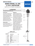
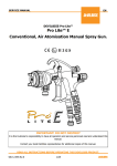
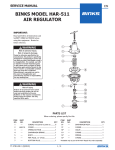
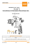
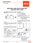
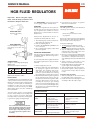
SERVICE MANUAL EN HGB FLUID REGULATORS Important: Before using this equipment, read all safety precautions and instructions. Keep for future use. Model HGB-502-1 Regulator Assembly Only See “ACCESSORIES” section for connections for riser, gauge, adapter and ball valves. 4.Periodically clean exterior of regulator with solvent soaked cloth. OPERATION Fluid pressure adjustment is done with a removable key (1). Insert large end of key into top of regulator. Turn clockwise to increase fluid pressure, counterclockwise to decrease fluid pressure. PARTS REPLACEMENT The HGB regulator may be serviced without removing it from the line. Fluid pressure adjustment can also be accomplished remotely with air control: 1.Turn adjusting key (1) fully counterclockwise turning the regulator off. 2.Remove adjusting key (1). 3.Install a 1/4” NPT(M) fitting H-2008 for air hose connection. 4.Use a regulated air supply to adjust fluid pressure regulator. Model HGB-508-1 Includes HGB-502-1 regulator plus gauge, riser tube and fittings. PREVENTIVE MAINTENANCE Periodic cleaning of regulator with a solvent compatible with the material being used is recommended. SPECIFICATIONS: Height: 5” (excluding adjusting key) Width: 2-7/8” Wetted parts: Stainless steel/nylon Inlet Pressure Regulated Max . Fluid Max. Min. Outlet Press. Flow Connections 175 psi 50 psi 10-75 psi 8 gal/min. 3/8”NPT(F) Maximum temperature 180°F. INSTALLATION The HGB regulator is provided with two side outlet ports and one bottom inlet port, all 3/8” NPT(F). The regulator may be installed either vertically or horizontally for flexibility of installation. In either case, riser and gauge should be mounted vertically. The HGB508 includes gauge, riser tube and fittings factory installed. Since the gauge operates on air trapped in the riser, a rise is always necessary. Any leaks in riser or gauge connections will permit this trapped air to escape thus allowing paint to get into the gauge causing damage. It is recommended that at initial installation the material supply line should not be flushed through the regulator because pipe compound, chips, scale, etc., may lodge in the regulator valve assembly. SB-6-375-E (7/2014) To clean material from the regulated material line and the regulator, these steps should be followed: 1.Relieve supply line pressure. 2.Using the small end of the adjusting key (1), engage the regulator and screw it down tight. This holds the valve off its seat. Also, the key may be used in this position to prevent waste from entering the regulator when spray booth is cleaned. 3.Blow material back through the regulated line by introducing air pressure into the line down stream from the regulator. With spray gun attached, this can be done by loosening air cap ring on gun, holding cloth over air cap and pulling trigger. This forces air in a reverse path through spray gun and air forces material back through regulated material line. Note Relieve line pressure before servicing regulator. Remove six socket head cap screws (2) with a 5/32’’ hex key. The small end of the adjusting key (1) may be used for this purpose. To Replace Diaphragm: 1.The diaphragm socket (B) has an arrow stamped on top. Curl the edge of the diaphragm up where the arrows point. 2.Slip the diaphragm assembly out from under the valve stem nut (C) so the nut is released from the socket (B). 3.Remove nut (A) and pull off diaphragms (7). Install 2 new diaphragms over threaded end of the socket (B). Convex sides of each diaphragm must be toward threaded end. 4.Apply retaining compound to male threads as shown and install nut (A). 5.Install diaphragm into body by again curling the edges of the diaphragms. 6.Slip socket (B) under valve stem nut (C). 7.Reassemble regulator body. Tighten all six cap screws evenly to 65 to 75 in./lbs. torque. To Replace Valve Assembly: 1.Valve assembly (9) can be removed from the body with a 3/4” socket wrench. 2.Install new valve assembly. Tighten valve assembly to 20 to 25 in./lbs. torque. TROUBLESHOOTING CONDITION CAUSE CORRECTION Regulated pressure creep. Improper seating of valve stem on seat. Diaphragm leaking. Damaged valve seat. Be sure stem and seat are not damaged, worn or dirty. Replace. Replace seat and stem. Regulated pressure drop. Restriction in main material line or at valve inlet. Damaged diaphragm. Remove restriction. Fluid leakage from Loose cap screws (2). under bonnet. Damaged diaphragm. 1/4 Replace. Tighten all six cap screws evenly to 65 to 75 in./lbs. torque. Replace. EN SAFETY PRECAUTIONS This manual contains information that is important for you to know and understand. This information relates to USER SAFETY and PREVENTING EQUIPMENT PROBLEMS. To help you recognize this information, we use the following symbols. Please pay particular attention to these sections. Note Important safety information – A hazard that may cause serious injury or loss of life. Important information that tells how to prevent damage to equipment, or how to avoid a situation that may cause minor inury. Information that you should pay special attention to. Read the following warnings before using this equipment. READ THE MANUAL Before operating finishing equipment, read and understand all safety, operation and maintenance information provided in the operation manual. ELECTRIC SHOCK/GROUNDING Improper grounding or sparks can cause a hazardous condition and result in fire, explosion or electric shock and other serious injury. WEAR SAFETY GLASSES Failure to wear safety glasses with side shields could result in serious eye injury or blindness. PROJECTILE HAZARD You may be injured by venting liquids or gases that are released under pressure, or flying debris. DE-ENERGIZE, DEPRESSURIZE, DISCONNECT AND LOCK OUT ALL POWER SOURCES DURING MAINTENANCE Failure to De-energize, disconnect and lock out all power supplies before performing equipment maintenance could cause serious injury or death. INSPECT THE EQUIPMENT DAILY Inspect the equipment for worn or broken parts on a daily basis. Do not operate the equipment if you are uncertain about its condition. OPERATOR TRAINING All personnel must be trained before operating finishing equipment. NEVER MODIFY THE EQUIPMENT Do not modify the equipment unless the manufacturer provides written approval. EQUIPMENT MISUSE HAZARD Equipment misuse can cause the equipment to rupture, malfunction, or start unexpectedly and result in serious injury. FIRE AND EXPLOSION HAZARD Improper equipment grounding, poor ventilation, open flame or sparks can cause hazardous conditions and result in fire or explosion and serious injury. KEEP EQUIPMENT GUARDS IN PLACE Do not operate the equipment if the safety devices have been removed. KNOW WHERE AND HOW TO SHUT OFF THE EQUIPMENT IN CASE OF AN EMERGENCY HIGH PRESSURE CONSIDERATION High pressure can cause serious injury. Relieve all pressure before servicing. Spray from the spray gun, hose leaks, or ruptured components can inject fluid into your body and cause extremely serious injury. STATIC CHARGE Fluid may develop a static charge that must be dissipated through proper grounding of the equipment, objects to be sprayed and all other electrically conductive objects in the dispensing area. Improper grounding or sparks can cause a hazardous condition and result in fire, explosion or electric shock and other serious injury. PRESSURE RELIEF PROCEDURE Always follow the pressure relief procedure in the equipment instruction manual. CA PROP 65 PROP 65 WARNING WARNING: This product contains chemicals known to the State of California to cause cancer and birth defects or other reproductive harm. IT IS THE RESPONSIBILITY OF THE EMPLOYER TO PROVIDE THIS INFORMATION TO THE OPERATOR OF THE EQUIPMENT. FOR FURTHER SAFETY INFORMATION REGARDING BINKS AND DEVILBISS EQUIPMENT, SEE THE GENERAL EQUIPMENT SAFETY BOOKLET (77-5300). 2/4 SB-6-375-E (7/2014) EN This end for pressure adjustment HGB-508-1 1 6 This end for back flushing HGB-502-1 A Torque to 65-75 in./lbs. 11 •8 15 14 •7 2 •8 L.H. Thread Apply retaining compound on male threads at assembly B 3 9 4 12 13 Do not over tighten. Max. torque 20-25 in./lbs. 10 5 Outlet Outlet Parts List Ref. Replacement No. Part No. Description 1 HGB-404-1 2 SSF-3167-K6 3 HGB-408 4 HGB-7 5 HGB-403 6 HGB-13 +•7 HGB-16-K10 •8 KK-4216 9 HGB-406-4-K Individual Parts Req. Adjusting Key Cap Screw (Kit of 6) Adjusting Screw Assembly Adjusting Nut Pin Assembly Spring Diaphragm Kit, Nylon II (Kit of 10) Diaphragm Hardware Kit Valve Assembly Kit 1 6 1 1 1 1 2 1 1 Ref. Replacement No. Part No. Description Individual Parts Req. *10 S/S Plug, 3/8” NPT(M) 1 11 83-2727 Gauge (0-100#) 1 12 HGB-14 Riser Tube, Stainless Steel 1 13 PLH-6SN-6TSS Swivel Fitting, S.S. 1 14 PLH-6-6T-SS Fitting, Stainless Steel 1 n15 83-2290 Glass Lens 1 • All kits contain parts shown plus retaining compound for use at assembly. +Kit contains 10 diaphragms. Only 2 are used in regulator. Diaphragms are only available in kit form. nAvailable separately. Order 83-2290. * Purchase locally. ACCESSORIES HGB-14 Riser Tube 3/8” NPT(M) x 1/4” NPT(F) Stainless Steel, 3-1/2” for elevated mounting of gauge SB-6-375-E (7/2014) 83-2727 Air Pressure 0-100 PSI Gauge H-2008 Adapter 1/4” NPT(M), 2-3/16” diameter, requires riser tube. 1/4” NPS(M) x 1/4” NPT(M) for adapting regulator to remote air control. 3/4 VA-527 Ball Valve S/S 3/8” NPS(M) x 3/8” NPT(M) EN WARRANTY POLICY DeVilbiss products are covered by Finishing Brands one year materials and workmanship limited warranty. The use of any parts or accessories, from a source other than Finishing Brands, will void all warranties. For specific warranty information please contact the closest Finishing Brands location listed below. Finishing Brands reserves the right to modify equipment specifications without prior notice. DeVilbiss, Ransburg, BGK, and Binks are registered trademarks of Finishing Brands. ©2014 Finishing Brands. All rights reserved. DeVilbiss is part of Finishing Brands, a global leader in innovative spray finishing technologies. For technical assistance or to locate an authorized distributor, contact one of our international sales and customer support locations below. USA/Canada www.devilbiss.com [email protected] Tel: 1-800-992-4657 Fax: 1-888-246-5732 Mexico www.finishingbrands.com.mx [email protected] Tel: 011 52 55 5321 2300 Fax: 011 52 55 5310 4790 Brazil www.devilbiss.com.br [email protected] Tel: +55 11 5641 2776 Fax: 55 11 5641 1256 United Kingdom www.finishingbrands.eu [email protected] Tel: +44 (0)1202 571 111 Fax: +44 (0)1202 573 488 France www.finishingbrands.eu [email protected] Tel: +33(0)475 75 27 00 Fax: +33(0)475 75 27 59 Germany www.finishingbrands.eu [email protected] Tel: +49 (0) 6074 403 1 Fax: +49 (0) 6074 403 281 China www.finishingbrands.com.cn [email protected] Tel: +8621-3373 0108 Fax: +8621-3373 0308 Japan www.ransburg.co.jp [email protected] Tel: 081 45 785 6421 Fax: 081 45 785 6517 Australia www.finishingbrands.com.au [email protected] Tel: +61 (0) 2 8525 7555 Fax: +61 (0) 2 8525 7500 4/4 SB-6-375-E (7/2014)