1
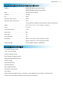
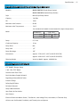
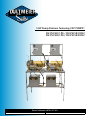
5 HP Pump Stations featuring CAT PUMPS®
DU PS1501C-PG / DU PS1501CPG2
DU PS1503C-PG / DU PS1503CPG2
Owner’s Manual #0781 071811
Serial Number:
Installation Date:
IMPORTANT
Please read and
understand this
manual. Store in
s a fe l oc a t i on for
future reference.
Everyone who operates this unit should understand basic operations and safety precautions!
The time you take to fully understand the proper installation, maintenance and use of the machine will
prolong its service life, and assure you of trouble free operation.
When unpacking, check to make sure all the parts shown on the Parts Breakdown near the end of this
manual are included. If any parts are missing or broken, please call Dultmeier Sales as soon as possible.
Consumers should notice that this manual may differ slightly from the actual product as more improvements
are made to our products. Some of the pictures in this manual may differ slightly from the actual product
as well. Dultmeier Sales reserves the right to update designs and / or change the specifications at any
time without incurring any obligation to install them on units previously sold.
If you have any questions or suggestions about this manual, please contact us.
Table of Contents
Safety Information ....................................................................................................................................
Specifications ...........................................................................................................................................
Installation & Operating Instructions..........................................................................................................
Parts Breakdown .......................................................................................................................................
Warranty Information ................................................................................................................................
Checklist ..................................................................................................................................................
Dultmeier Sales, LLC
1.800.228.9666 • Fax: 1.402.333.5546 • 13808 Industrial Road Omaha, NE 68137
1.800.553.6975 • Fax: 1.319.386.5448 • 601 West 76th Street Davenport, IA 52806
http://www.dultmeier.com • [email protected]
1
2-3
4-6
7
8
9
Safety Information | 1
To avoid serious or fatal personal injury or major property damage,
read and follow all safety and operation instructions in the manual.
This is a Safety Alert Symbol When you see this symbol in the manual, look for the following signal words &
be alert to the potential for personal injury or property damage.
DANGER
Warns of potential hazards that WILL cause serious personal injury, death or property damage.
WARNING
Warns of potential hazards that CAN cause serious personal injury, death or property damage.
CAUTION
Warns of potential hazards that WILL or CAN cause minor personal injury, death or property damage.
IMPORTANT Indicates special instructions that MUST be followed but not related to hazards.
This manual is intended to assist in the installation and operation of this unit.
Do not attempt to operate this unit without reading and understanding this manual.
General Safety
To avoid the risk of serious bodily injury and property damage, read safety instructions carefully before installing
this system. Follow all local and/or national plumbing and electrical codes when installing.
IMPORTANT
WARNING
WARNING
Hazardous voltage
can shock, burn
or cause death.
Do Not Allow System or Components to Freeze.
To do so may damage the system and will void the warranty.
Never Run the System Dry.
Running the unit dry (without fluid) can damage internal parts, overheat pump (which can cause
burns to people handling or servicing the pump), and will void the warranty.
Risk of Electric Shock.
Keep the unit dry at all times Do not wash the motor or electrical panel or allow the unit to sit in standing water.
Use only Ground Fault Circuit Interrupter (GFCI) protected grounded outlet for the cord plug.
If you must use an extension cord, use only UL approved indoor/outdoor, 3-wire, grounding
type cords. The cord must be rated to support amp draw. Do not allow any part of cord or
receptacle ends to sit in water.
To avoid fatal shocks, proceed as follows if service is needed:
A. Turn off water to the system.
B. Disconnect the power at main electrical service before unplugging the unit.
C. Ground the electrical outlet box.
D. Take extreme care when changing fuses.
IMPORTANT
Check for
Proper Rotation
Pump was designed for forward rotation to allow
optimum lubrication of the crosshead area.
Reverse rotation is acceptable if the crankcase
oil level is increased slightly above center dot to
assure adequate lubrication.
CAUTION
Burn Hazard
Do Not Touch An
Operating Motor
Modern motors can operate at high temperatures.
To avoid burns when servicing pump, allow it
to cool for 20 minutes after shutdown before
handling.
Specifications | 2
Single & Double Wash Pump Station Specifications
Model(s) .................................................. DU PS1501C-PG (Single Pump Station)
DU PS1501CPG2 (Double Pump Station)
Style......................................................... Bench Style Pump Station
Capacity................................................... 3.8 GPM
PSI............................................................ 1800
Maximum Inlet Pressure............................ 60 PSI
Maximum Inlet Temperature..................... 130° F
*See Included CAT PUMPS® Service Manual for Higher Temperatures
Motor....................................................... CE 131538 :: 5 HP / 1 PH, 230 Volts / 23 Amps
Pump........................................................ CC 310S
Crankcase Capacity................................... 18 oz.
Pump Drive............................................... Belt
Pump Inlet................................................ 1/2”
Pump Discharge........................................ 3/8”
Dimensions............................................... Approx. 22”W x 29”L x 62”H (DU PS1501C-PG)
Approx. 44”W x 29”L x 62”H (DU PS1501CPG2)
Shipping Weight........................................ Varies by Model, Approx. 400-800 lbs.
System Features & Options
CAT PUMPS® Plunger Pump
5 HP, 1 PH, TEFC Motor
Stainless Steel Float Tank
Dual Inlet Water Supply Solenoid
Regulating Balanced Relief Valve
Pressure Gauge
Safety Pop Off Valve
Pulsation Dampner
Soap & Wax Solenoids
Inlet Check & Gate Valves
Inlet Strainer
Electrical Panel with Motor Starter, Transformer, Low Voltage Fuse, Hour Meter, & Terminal Strip
All Units are Pre-Plumbed, Pre-Wired, and Tested prior to shipment
Specifications | 3
Single & Double Wash Pump Station Specifications
Model(s) .................................................. DU PS1503C-PG (Single Pump Station)
DU PS1503CPG2 (Double Pump Station)
Style......................................................... Bench Style Pump Station
Capacity................................................... 3.8 GPM
PSI............................................................ 1800
Maximum Inlet Pressure............................ 60 PSI
Maximum Inlet Temperature..................... 130° F
*See Included CAT PUMPS® Service Manual for Higher Temperatures
Motor....................................................... CE EM3615T
Volts:
5 HP, 3 PH
208 - 230
Amps: 13.9 - 13.4
460
6.7
Pump........................................................ CC 310S
Crankcase Capacity................................... 18 oz.
Pump Drive............................................... Belt
Pump Inlet................................................ 1/2”
Pump Discharge........................................ 3/8”
Dimensions............................................... Approx. 22”W x 29”L x 62”H (DU PS1503C-PG)
Approx. 44”W x 29”L x 62”H (DU PS1503CPG2)
Shipping Weight........................................ Varies by Model, Approx. 400-800 lbs.
System Features & Options
CAT PUMPS® Plunger Pump
5 HP, 3 PH, TEFC Motor
Stainless Steel Float Tank
Dual Inlet Water Supply Solenoid
Regulating Balanced Relief Valve
Pressure Gauge
Safety Pop Off Valve
Pulsation Dampner
Soap & Wax Solenoids
Inlet Check & Gate Valves
Inlet Strainer
Electrical Panel with Motor Starter, Transformer, Low Voltage Fuse, Hour Meter, & Terminal Strip
All Units are Pre-Plumbed, Pre-Wired, and Tested prior to shipment
Installation & Operating Instructions | 4
Placement
1. Place Pump Station on level floor near water
source, electrical supply, and floor drain. Surface
must be as level as possible.
2. Use rubber mounting feet to level station.
(Fig. 1)
figure 1
Electrical
1. Electrician to run power from Main Electrical Panel
to the Disconnect in the control panel. (Fig. 2)
IMPORTANT
For branch service protection & to size
wire see decal on control panel door.
Main
Electrical Panel
Control Panel
2. Electrician to run control cable* from control panel
to the selector switch or coin box.
Selector
Switch
3. Terminate control cable to terminal blocks in
control panel. Match all color schemes. Use
ground bar for all 24V common (Fig. 2)
IMPORTANT
For terminal block identification see
decal on control panel door.
4. Use molex connectors & fittings (provided) on
selector switch or coin meter box. This will allow
you to simply unplug the units from the wall if
service is required. (Fig. 3)
IMPORTANT
It is recommended you use a molex
crimp tool. This will give a tight even
crimp around the molex pin.
Ground Bar
Disconnect
figure 2
To Order Use Part Numbers:
RV T-18
Delux Crimper
UT GCE12464
Crimper
UT MOL11030006
Extra Tool
figure 3
Installation & Operating Instructions | 5
Plumbing
1. Plumber to run soft water city pressure line to cold
water side of dual solenoid (front MGHF) fitting
on inlet of water supply tank. (Fig. 4) Run soft hot
water line from boiler or heater to hot water side
of dual solenoid (back MGHF).
IMPORTANT
Water supply pressure should not
exceed 60 PSI. Plumber to supply
pressure regulator if required.
2. Run hard water weep line from normally open
weep solenoid to weep inlet on Pump Station.
3. Measure hose run lines from Pump Station to
bay booms and assemble hoses with reuseable
fittings. Connect high pressure run hose to boom
inlet. (Fig. 5) Connect other end of run hose to
swivel union on discharge of pump.
IMPORTANT
Make sure hose is protected from
wearing against any rough surface
due to vibration.
4. Install boom and trigger gun package in bay.
5. Install manifolds for any secondary systems as
required.
Hot Water Connection: FGHF on the left.
Cold Water Connection: FGHF on the right.
figure 4
Bay Run Hose Union
Connect bay run hose at boom
first. Connect other end to this
union on discharge of pump.
figure 5
Chemical Setup
1. Set or mount Soap tank in place near Pump Station
and run city pressure soft water line to inlet of
tank. Select proper mix tip for soap and screw into
chemical inlet port on Hydrominder eductor.
(Fig. 6)
Consult Hydrominder instructions and chemical
product label for further dilution information.
Select proper chemical
mixing tip and screw
into eductor inlet port.
2. Attach chemical pickup tubing to chemical inlet
port on eductor and place other end with foot
valve strainer and weight into bulk soap container.
3. Repeat these steps for wax.
figure 6
Installation & Operating Instructions | 6
Testing & Operation
1. Remove nozzle from gun assembly in bay. Place
rotary switch in bay on rinse position. Place rinse
changeover switch on Pump Station Electrical
Panel on cold water position. Activate system and
run for one minute to purge any foreign materials
and air from the line.
WARNING
Pressure should be set with trigger
open. With trigger closed pressure
will spike approx. 100 PSI.
3. Place rinse changeover switch to hot water
position and make sure water heater or boiler is
working.
4. Place bay switch on soap position. Pump suction
for soap and wax is set at factory with inlet line
gate valve. Inlet flow to pump is restricted with
gate valve to create .5 inches of vacuum at the
pump. There should be no need to change this
setting. (Fig. 8)
CAUTION
Turn Handle:
Clockwise to increase pressure &
Counter-Clockwise to decrease pressure
Hazardous Pressure.
Do not discharge toward body.
2. Replace nozzle and restart system. Pressure is set
at factory. Open and close trigger gun slowly to
ensure that pressure is balanced properly. Make
adjustments at handle on balanced relief valve if
needed. (Fig. 7)
IMPORTANT
Balanced Relief Valve
Do not let the pump run for a long
amount of time without the proper
flow.
5. Adjust metering screw on soap solenoid until
desired strength of soap appears in bay.
(Fig. 9) With screw fully open chemical draw is 25
oz. per minute. You may have to experiment with
concentration in soap pre-mix tank.
6. Repeat these steps for wax.
7. Test secondary systems as necessary. Consult
instruction manual supplied with each system.
figure 7
Gate Valve
Turn handle Clockwise until pump
starts to chatter due to flow loss. Turn
Counter-Clockwise to point where
pump chattering smooths out.
figure 8
Soap & Wax Solenoids
Metering Screw. Turn Clockwise
for decrease in flow and CounterClockwise for increase in flow.
figure 9
Parts Breakdown | 7
Parts Breakdown: DU PS1501C-PG & DU PS1503C-PG
13
1
12
11
10
2
3
9
8
4
7
5
6
Item
Part Number
Description
  1........... CE 131538............... Motor 5 HP, Single Phase
.......... CE EM3615T............. Motor 5 HP, Three Phase
  2........... KI 3X293.................. Soap & Wax Solenoids with Meter
.......... PA 3X293................. Replacement Plunger
  3........... IP 100534................ Safety Pop Off Valve
  4........... SM 687-12E.............. Check Valve
  5........... TW GV-3/4............... Gate Valve
  6........... DE S6B-80................ Bronze Strainer, 3/4”
  7........... DU 33812-24........... Dual Inlet Solenoid
.......... DU 338K.................. Dual Inlet Solenoid Repair Kit
  8........... GE 3000-4................ Weep Globe Valve
  9........... SM 470-4F4F............ Weep Check Valve
10........... CC 310S................... Stainless Steel CAT PUMPS® Plunger Pump
11........... AH 2750-4............... Pressure Gauge
12........... NP ST230................. Balanced Relief Valve
.......... NP RK230................. Balanced Relief Valve Repair Kit
13........... HY 3375-8................ Pulse Hose
........... RB R400-1/2............. Float Valve (Not Visible, Located Inside Tank)
.......... GA B46..................... Drive Belts (Not Visible, Located Inside Belt Guard)
Warranty Information | 8
Notice Regarding Manufacturer’s Limited Warranty
Dultmeier Sales Limited Liability Company (hereinafter Dultmeier), notifies you that component
part(s) carry a manufacturer’s limited warranty provided by the manufacturer of said component
part(s). These warranties do not pertain to normal wear of component part(s) that may occur
within any specified period. While Dultmeier is not the manufacturer of any of the component
part(s), Dultmeier will assist you in processing any and all manufacturer’s warranty claim if
applicable and available. Any and all manufacturer’s claims must be submitted in writing to the
manufacturer within the warranty periods provided by the manufacturer.
Defective component part(s) that are to be considered for manufacturer’s limited warranty must
be returned to the manufacturer by prepaid shipment with the applicable manufacturer’s limited
warranty period. If the component part(s) are deemed to be defective under the manufacturer’s
warranty, Dultmeier will assist in obtaining a replacement or repair of the component part(s). Said
component part(s) will be returned F.O.B. Omaha, Nebraska. Replacement or repair shall be the
exclusive remedy for any breach of warranty. Labor for installation, either with respect to original
or replacement part or components, is not covered under the manufacturer’s limited warranty.
Neither the manufacturer nor Dultmeier warrants loss of income or consequential damages for
injury or commercial loss resulting from any breach of warranty or warranties stated above.
The manufacturer’s limited warranty as stated does not apply to component part(s) which
have been improperly installed, misused, altered, neglected, abused or not installed, adjusted,
maintained, or used in accordance with applicable codes and ordinances and in accordance with
the manufacturer’s specifications as to such factors.
Notwithstanding Dultmeier’s willingness to assist in the processing of the manufacturer’s limited
warranty, Dultmeier makes no warranty against infringement of the like, makes no warranty
of merchantability, makes no warranty of fitness for a particular purpose, and makes no other
warranty, express or implied, including implied warranty arising from the course of dealing or
usage of trade.
Compliance with all local, state and federal codes regarding the installation and operation of said
equipment, parts and components shall be the responsibility of the purchaser. The rights and
obligations of the parties shall be governed by the laws of the State of Nebraska.
Dultmeier Sales • 1-800-228-9666 Omaha, NE • 1-800-553-6975 Davenport, IA
Checklist | 9
Production Checklist
OK
NA
Oil Level
OK
NA
Pop-Off Valve Set
OK
NA
Clamps Tight
OK
NA
Unloader Valve Locked
OK
NA
Bolts Tight & Anti-Seized
OK
NA
PSI
OK
NA
Belts Tight
OK
NA
Pump RPM
OK
NA
Pulleys Aligned & Torqued to Specifications
OK
NA
Motor Amps
OK
NA
Fittings Straight
OK
NA
Motor Wired For
OK
NA
Check Valves
OK
NA
Solenoids
Weep
PSI
Accessories
Soap
OK
NA
Electrical Drawing
Soap
OK
NA
UL Inspected & Tagged
Wax
OK
NA
EP1 Selector Switch
Hot Water
OK
NA
TF 1 Chemical Hose
Cold Water
OK
NA
Weights & Strainers
OK
NA
Tested
OK
NA
Trigger Gun
OK
NA
Winterized
OK
NA
Leveling Bolts
OK
NA
OK
NA
OK
NA
OK
NA
OK
NA
OK
NA
OK
NA
1
2
Additional Parts Shipped in Container
Built By
Checked By
Customer Checklist
OK
NA
Oil Level To Manufacturer’s Specifications
OK
NA
Accessories Included
OK
NA
Shipping Container Was In Good Shape
OK
NA
Overall Condition
If you have any questions or concerns about condition of this unit, please contact us before operating.
Dultmeier Sales, LLC
Omaha, NE 1.800.228.9666 • Davenport, IA 1.800.553.6975
http://www.dultmeier.com • [email protected]