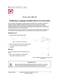
1
User's
User’s
Manual
Manual
Issue 01 / March 2013 / OIAI Cryo-Plex 10
Cryo-Plex 10® Cryogenic High Vacuum Pump
Oxford Instruments
Austin, Inc.
Cryo-Plex 10® Cryogenic High Vacuum Pump
Issue 01 / March 2013 / Original Instructions
Issue 01 ©2013 Oxford Instruments Austin, Inc.. All rights reserved.
OIAI Cryo-Plex 10 Original Instructions
User's Manual
Issue 01 / March 2013 / OIAI Cryo-Plex 10
Cryo-Plex 10® Cryogenic High Vacuum Pump
Oxford Instruments Austin, Inc. is a wholly-owned subsidiary of Oxford Instruments. For information
about Oxford Instruments, visit the Oxford Instruments Web site at:
http://www.oxford-instruments.com
How to Contact Oxford Instruments Austin, Inc. Support:
[email protected]
For contact information and a complete listing of Direct Sales, Distributor, and Sales Representative
contacts, visit the Oxford Instruments Austin, Inc. Web site at:
http://www.oxford-instruments.com/businesses/industrial-products/austin
Oxford Instruments Austin, Inc. has made its best effort to ensure that the information contained in this
document is accurate and reliable. However, the information is subject to change without notice and is provided
“AS IS” without warranty of any kind (express or implied). Before placing orders, customers are advised to
obtain the latest version of relevant information to verify that information being relied upon is current and
complete. All products are sold subject to the terms and conditions of sale supplied at the time of order
acknowledgment, including those pertaining to warranty, patent infringement, and limitation of liability. No
responsibility is assumed by Oxford Instruments Austin, Inc. for the use of this information, including use of this
information as the basis for manufacture or sale of any items, nor for infringements of patents or other rights of
third parties. This document is the property of Oxford Instruments Austin, Inc. and by furnishing this
information, Oxford Instruments Austin, Inc. grants no license, expressed or implied, under any patents,
copyrights, trademarks, trade secrets, or other intellectual property rights of Austin Scientific. Austin Scientific,
copyright owner of the information contained herein, gives consent for copies to be made of the information
only for use within the customer’s organization as related to the use of Oxford Instruments Austin, Inc.
products. The same consent is given for similar information contained on any Oxford Instruments Austin, Inc.
Web site or disk used to distribute information to a customer. Oxford Instruments Austin, Inc. does give consent
to the copying or reproduction by any means of the information contained herein for general distribution,
advertising or promotional purposes, or for creating any work for resale. The names of products of Oxford
Instruments Austin, Inc. or other vendors and suppliers appearing in this document may be trademarks or
service marks of their respective owners that may be registered in some jurisdictions. A list of Oxford
Instruments Austin, Inc. trademarks and service marks can be found at:
http://www.oxford-instruments.com/businesses/industrial-products/austin
Oxford Instruments Austin, Inc.
1340 Airport Commerce Dr.
Bldg. 1 Suite 175
Austin, Texas 78741 USA
TEL. +1 512 441 6893
FAX +1 512 443 6665
Email: [email protected]
Copyright (©) 2013 by Oxford Instruments, All rights reserved.
Issue 01 ©2013 Oxford Instruments Austin, Inc.. All rights reserved.
OIAI Cryo-Plex 10 Original Instructions
User's Manual
Issue 01 / March 2013 / OIAI Cryo-Plex 10
Cryo-Plex 10® Cryogenic High Vacuum Pump
Contents
1 Preface
1.1
1.2
1.3
1.4
About Austin Scientific
Other Services from Oxford Instruments Austin, Inc
About this Manual
Compatibility
2 Safety Warnings
2.1
Safety Warnings
2.1.1 Standards for the Use of Warnings and Cautions
2.1.2 Warnings Applicable to All Aspects of the Operation of Cryo-Plex 10 Cryopumps
2.1.3 Operator Instructions
3 Introduction
3.1
General Information about the Cryo-Plex 10 Cryopump
3.1.1 Cryo-Plex 10 Cryopump Features
3.2
Specifications
3.3
Ordering Information
3.3.1 Standard Equipment and Accessories
3.3.2 Optional Accessories and Replacement Parts
4 Installation
4.1
4.2
4.3
4.4
4.5
Safety Warnings
Inspect Equipment before Installing
Tools Needed for Installation
Installing the Cryo-Plex 10 Cryopump
Installing a Roughing Pump
5 Operations and Controls
5.1
Cryo-Plex 10 Cryopump Operations
5.1.1 Cryopump Preparation
5.1.2 Normal Operation
5.1.2.1 Cryopump Start-up
5.1.2.2 Rough Pumping
5.1.2.3 Regeneration of the Cryopump
6 Troubleshooting
6.1
Troubleshooting Activities
7 Maintenance
7.1
Maintenance Personnel Requirements
7.2
Tools Needed to Service the Cryo-Plex 10 Cryopump
7.3
Scheduled Preventative Maintenance
7.3.1 Preparation Before Decontamination
7.3.2 Purging the Regulator and Charging Line
7.3.3 Pressurize and Vent the Cold Head
7.3.4 Reconnect Gas Lines to Complete Decontamination
7.4
Cleaning Equipment
7.5
Returning Equipment
Issue 01 ©2013 Oxford Instruments Austin, Inc.. All rights reserved.
OIAI Cryo-Plex 10 Original Instructions
User's Manual
Issue 01 / March 2013 / OIAI Cryo-Plex 10
Cryo-Plex 10® Cryogenic High Vacuum Pump
Figures
3-1
3-2
4-1
Dimensions of Cryo-Plex 10 Cryopump with CF Inlet
Dimensions of Cryo-Plex 10 Cryopump with ANSI Flange
Connection Diagram
Tables
3-1
3-2
3-3
6-1
Cryo-Plex 10 Physical Characteristics
Cryo-Plex 10 Cryopump Ordering Information
Optional Accessories and Replacement Parts
Troubleshooting Procedures
Revision History
Date
September 2006
March 2013
Version
1.0.1
1.2
Reason
Original Release
Format and Facilities Address Update
Issue 01 ©2013 Oxford Instruments Austin, Inc.. All rights reserved.
OIAI Cryo-Plex 10 Original Instructions
User's Manual
Issue 01 / March 2013 / OIAI Cryo-Plex 10
Cryo-Plex 10® Cryogenic High Vacuum Pump
Preface 1
1.1 About Austin Scientific
Oxford Instruments Austin, Inc., a wholly-owned subsidiary of Oxford Instruments, specializes in the
manufacture and repair of cryogenic vacuum pumps, cryocoolers (refrigerators) and helium compressors for
semiconductor, optical coating, linear accelerators, medical equipment, and R&D applications.
You can find just what you need from our range of products and support services.
• New equipment - cryopumps, such as the Cryo-Plex 10 cryopumps described in this manual, compressors, cryocoolers,
and cryopump controllers.
• Comprehensive range of accessories for the installation of whole systems and a complete range of spare parts to repair
cryopumps and compressors.
1.2 Other Services from Austin Scientific
Oxford Instruments Austin, Inc. offers a broad range of additional services:
• Repair and refurbishment services - Whatever brand of cryo-components you have, we offer fully warranted
refurbishment, often with off-the-shelf availability.
• Exchanges - We offer our own quality products, as well as most makes of cryopumps and helium compressors, which are
refurbished and fully warranted.
• Technical Support - Our support engineers will help determine if your cryopump system is operating correctly so that you
can get your system back to optimum efficiency as soon as possible.
To contact Oxford Instruments Austin, Inc. Technical Support:
Email: [email protected]
• Telephone: 1-512-441-6893 or Toll Free: 1-800-404-1055
• Installation - On-site installation services are available to guarantee performance and save you time.
• Training - We offer on-site training to help you and your staff to know more about your cryopump and compressor
systems. Our training will give you confidence and the ability to maintain a highest possible uptime for your system.
1.3 About this Manual
The purpose of this manual is to provide our customers using the Cryo-Plex 10 Cryopumps with information
needed to safely and efficiently operate the cryopump when operating as part of a cryogenic refrigeration
system. Such a system is often comprised of the following equipment:
• Cryopump compressor unit such as the Model 600 compressor from Austin Scientific
• Coldhead/cryopump
• Connecting helium lines.
This manual describes the design, operation and maintenance of a Cryo-Plex 10 cryopump unit.
Issue 01 ©2013 Oxford Instruments Austin, Inc.. All rights reserved.
OIAI Cryo-Plex 10 Original Instructions
User's Manual
Issue 01 / March 2013 / OIAI Cryo-Plex 10
Cryo-Plex 10® Cryogenic High Vacuum Pump
1.4 Compatibility
The Cryo-Plex 10 cryopumps are designed for use with Oxford Instruments Austin, Inc. Model 600 helium
compressor (or equivalent).
Safety Warnings 2
2.1 Safety Warnings
2.1.1 Standards for the Use of Warnings and Cautions
Warnings are noted when there is a possibility of injury or death to persons operating the equipment or
performing specific tasks or procedures noted in this manual. Cautions are noted when there is a possibility of
damage to equipment if the caution is ignored.
2.1.2 Warnings Applicable to All Aspects of the Operation of Cryo-Plex 10 Cryopumps
Warning
If the Cryo-Plex 10 cryopump has been used to pump any toxic or dangerous materials, this
information and associated paperwork must be listed on all shipping containers and on associated
paperwork before the equipment is returned to Oxford Instruments Austin, Inc. for any repairs.
Warning
When pumping any toxic, corrosive, or flammable gases, a vent pipe must be connected to the
cryopump relief valve and vented to a safe location.
Warning
Do not install a hot filament vacuum gauge on the cryopump side of the hi-vac gate valve as this could
be a source of ignition.
Warning
Helium gas can cause rapid asphyxiation and death if released in a confined area.
Warning
Use a pressure reducing regulator when with-drawing Helium gases from a high pressure cylinder
Warning
Detaching the helium flex lines with the compressor load at low temperature can cause the pressure
rise in the system beyond the permissible level therefore creating a safety hazard.
Issue 01 ©2013 Oxford Instruments Austin, Inc.. All rights reserved.
OIAI Cryo-Plex 10 Original Instructions
User's Manual
Issue 01 / March 2013 / OIAI Cryo-Plex 10
Cryo-Plex 10® Cryogenic High Vacuum Pump
2.1.3 Operator Instructions
Follow standard Cryo-Plex 10 operating procedures as described in this manual. If after reading this manual,
you still have questions regarding the safe operation of the CP10 cryopump, please contact Oxford Instruments
Austin, Inc. Technical Support using the contact information found in Chapter 1, Section 1.2.
Introduction 3
3.1 General Information about the Cryo-Plex 10 Cryopump
Oxford Instruments Austin, Inc. provides both custom and industry standard cryogenic solutions at highly
competitive prices. Cryogenic vacuum pumps provide clean, oil-free high vacuum with high pumping speeds
are the pump of choice for sputtering, electron beam evaporation, accelerator beam lines and many aerospace
and coating applications. Cryo-Plex 10 cryopumps are available in various standard inlet flange configurations ANSI, ISO, CF and complete UHV, with temperature sensors either in diode or hydrogen-vapor-bulb (HVB)
configurations.
3.1.1 Cryo-Plex 10 Cryopump Features
The Cryo-Plex 10 cryopumps, as seen in Figure 3-1, are typically used in the following applications:
• Sputtering tools
• Ion implanters
• R & D bell-jar systems
• Surface analysis
• Accelerators
• Beam lines
• General vacuum systems
Issue 01 ©2013 Oxford Instruments Austin, Inc.. All rights reserved.
OIAI Cryo-Plex 10 Original Instructions
User's Manual
Issue 01 / March 2013 / OIAI Cryo-Plex 10
Cryo-Plex 10® Cryogenic High Vacuum Pump
3.2 Specifications
This section describes the specifications for the Cryo-Plex 10 cryopumps.
Table 3-1
Cryo-Plex 10 Characteristics
Characteristic
Height
Maximum Flange Diameter
Weight
ANSI Flange
23.9 Inches
16.0 Inches
85 lbs
ISO Flange
23.9 Inches
14.5 Inches
85 lbs
• Pumping Speeds (liter/sec.)
— Air: 3000
— Water: 9000
— Hydrogen: 5000
— Argon: 2500
• Argon Throughput
— 1500 scc/min.
• Capacity:
— Argon: 2000 standard liters
— Hydrogen: 24 standard liters @ 5x10e-6 torr
• Crossover: 300 torr-liters
• Cool Down Time (Room temperature to 20K): 120 minutes
• Inlet Flange (Size: Standard)
— 10-inch: ANSI
— 14-inch: CF
— NW 320: ISO
Note: Cryo-Plex 10 cryopumps can operate safely in any mounting orientation.
Issue 01 ©2013 Oxford Instruments Austin, Inc.. All rights reserved.
OIAI Cryo-Plex 10 Original Instructions
Conflat Flange
23.9 Inches
14.0 Inches
85 lbs
User's Manual
Issue 01 / March 2013 / OIAI Cryo-Plex 10
Cryo-Plex 10® Cryogenic High Vacuum Pump
Figure 3-1. Dimensions of Cryo-Plex 10 Cryopump with CF Inlet (Larger Print at the End of Manual)
Issue 01 ©2013 Oxford Instruments Austin, Inc.. All rights reserved.
OIAI Cryo-Plex 10 Original Instructions
User's Manual
Issue 01 / March 2013 / OIAI Cryo-Plex 10
Cryo-Plex 10® Cryogenic High Vacuum Pump
Figure 3-2. Dimensions of Cryo-Plex 10 Cryopump with ANSI Flange (Larger Print at the End of Manual)
Issue 01 ©2013 Oxford Instruments Austin, Inc.. All rights reserved.
OIAI Cryo-Plex 10 Original Instructions
User's Manual
Issue 01 / March 2013 / OIAI Cryo-Plex 10
Cryo-Plex 10® Cryogenic High Vacuum Pump
3.3 Ordering Information
3.3.1 Standard Equipment and Accessories
Table 3-2 contains the ordering information for the Cryo-Plex 10 Cryopumps.
Table 3-2. Cryo-Plex 10 Cryopump Ordering Information Cryopump Part Number
Cryopump
Cryo-Plex 10 (ANSI Flange, Diode)
Cryo-Plex 10 (ANSI Flange, HVB)
Cryo-Plex 10 (CF Inlet, Diode)
Cryo-Plex 10 (CF, UHV, HVB)
Cryo-Plex 10 (UHV, Diode)
Cryo-Plex 10 (UHV, HVB)
Cryo-Plex 10 (ISO, Diode)
Part number
10249
10250
10296
10297
10307
10308
92-00003-0SD
3.3.2 Optional Accessories and Replacement Parts
The customer can order the optional accessories and replacement parts listed in Table 3-3.
Table 3-3. Optional Accessories and Replacement Parts Accessories/Replacement Parts Part Number
Accessories/Replacement Parts
Blanket Heater
Purge Gas Valve
Purge Gas Valve Heater
Rough Valve
Burst Disc
Relief Valve Cover
Drive Unit Power Cable (10 ft.)
Diode Monitor
Diode Cable for Diode Monitor (10 ft.)
Model 2200 Automatic Cryopump Controller w/ RS232
(220V)
Single Pump Installation Kit
Issue 01 ©2013 Oxford Instruments Austin, Inc.. All rights reserved.
OIAI Cryo-Plex 10 Original Instructions
Part Number
BH-10
10185
10340
10191
BD-133
60210
10144-10
10132
10133-10
93-00015-232
10251
User's Manual
Issue 01 / March 2013 / OIAI Cryo-Plex 10
Cryo-Plex 10® Cryogenic High Vacuum Pump
Installation 4
4.1 Safety Warnings
Review the safety warnings found in Chapter 2 before starting any installation activities.
4.2 Inspect Equipment before Installing
Remove the cryopump from the box and inspect for any damage during shipping. Notify Austin
Scientific immediately if any damage was found.
4.3 Tools Needed for Installation
The Installation Kit for the Cryo-Plex 10 cryopump is offered as an optional accessory that can be ordered from
Oxford Instruments Austin, Inc. Refer to Chapter 3, Section 3.3 for the part number.
4.4 Installing the Cryo-Plex 10 Cryopump
Follow these steps to install the Cryo-Plex 10 cryopump.
1. Clean all sealing surfaces, apply a thin film of vacuum grease to inlet flange o-ring and install it.
2. Bolt cryopump to the chamber hi-vac gate valve.
3. Attach roughing valve to the KF 25 flange on the purge tube adaptor of the cryopump.
4. Remove dust plugs from any Aeroquip Self Sealing Couplings and inspect gasket seals.
5. Connect helium gas lines in the following order.
a. Use a helium flex line to connect the “Return” ports on both the Cryo-Plex 10 and the compressor.
b. Use a helium flex line to connect the “Supply” ports on both the Cryo-Plex 10 and the compressor.
6. Check gas pressure gauge per compressor specifications.
7. Connect cold-head drive cable from cryopump to compressor.
8. Connect diode cable to temperature monitor if applicable.
9. Connect main power cable per compressor specifications.
Figure 4.1 shows a typical installation diagram when making connections.
Issue 01 ©2013 Oxford Instruments Austin, Inc.. All rights reserved.
OIAI Cryo-Plex 10 Original Instructions
User's Manual
Issue 01 / March 2013 / OIAI Cryo-Plex 10
Cryo-Plex 10® Cryogenic High Vacuum Pump
Figure 4-1. Connection Diagram
4.5 Installing a Roughing Pump
To install a roughing pump, follow these steps:
1. Connect the roughing pump system directly to the accessory port located on the cryopump.
2. A vacuum gauge and roughing valve should be installed as close as possible to the cryopump.
3. Install an oil back streaming device (fore line trap) in series to the roughing pump.
Issue 01 ©2013 Oxford Instruments Austin, Inc.. All rights reserved.
OIAI Cryo-Plex 10 Original Instructions
User's Manual
Issue 01 / March 2013 / OIAI Cryo-Plex 10
Cryo-Plex 10® Cryogenic High Vacuum Pump
Operations and Controls 5
5.1 Cryo-Plex 10 Cryopump Operations
5.1.1 Cryopump Preparation
When a cryopump has been in storage for a period of time or when receiving a new one, the charcoal array of
the cryopump may be loaded with moisture or other contaminants. A so-called “Extended Nitrogen Purge”
process should be performed to get the cryopump to its desired condition before cool-down operation.
Follow these steps of the “Extended Nitrogen Purge” process:
1. Install the cryopump per procedures described in Chapter 4, Section 4.4, leak check all mounting seals and valves to
ensure the cryopump is leak-tight.
2. Make sure the cryopump is at room temperature.
3. Using a gas supply flex line with proper connections to connect a nitrogen gas (N2) cylinder (with a pressure regulator) to
the purge gas valve of the cryopump.
4. Open the purge gas valve and regulate the pressure of nitrogen gas to between 18 to 30 psi.
5. Turn on the purge gas heater.
6. Continue the purging process for at least 4 hours.
7. Turn off the purge gas heater and close the purge gas valve.
8. Clean and then remount the o-ring of the relief valve on the cryopump.
The cryopump unit is now ready for start-up operation.
5.1.2 Normal Operation
5.1.2.1 Cryopump Start-up
1. Make sure the gate valve to the main chamber is closed.
2. Open the rough valve of the cryopump and rough to appropriate crossover pressure level.
3. Perform Rate of Rise test to verify proper regeneration and leak rate of the cryopump. Normally a 10 micron/minute rate
of rise is considered acceptable. If the Rate of Rise test fails, leak check the cryopump and the gate valve first and fix any
leak that is present. If the test still fails after that, repeat the “Extended Nitrogen Purge” process described in Section 5.1.1.
4. Rough pump the cryopump back to its appropriate crossover pressure level.
5. Close the rough valve and start the compressor that runs the cryopump.
6. When a cryopump is operating properly, it usually takes about 90~100 minutes to reach 20K.
7. Once the cryopump reaches its operating cryogenic temperature, observe the pressure in the main vacuum chamber
before opening the gate valve and starting cryopumping the chamber.
8. The crossover of the main vacuum chamber from rough pump to cryopumping should be at 300 torr-liters.
Only open the gate valve when this condition is met.
Issue 01 ©2013 Oxford Instruments Austin, Inc.. All rights reserved.
OIAI Cryo-Plex 10 Original Instructions
User's Manual
Issue 01 / March 2013 / OIAI Cryo-Plex 10
Cryo-Plex 10® Cryogenic High Vacuum Pump
5.1.2.2 Rough Pumping
Observe the following cautions when rough pumping the cryopump:
Caution
Do not begin to rough pump the cryopump without knowing the pre-determined roughing pressure.
Caution
Never rough pump the cryopump longer than necessary, it could result in back streaming of
mechanical pump oil that will contaminate the cryopump.
5.1.2.3 Regeneration of the Cryopump.
Since cryopumps are capture type pumps, they must be periodically warmed up and evacuated in order to
remove the accumulated condensed and adsorbed gases. The process of warming up and evacuating gases
from a cryopump is called regeneration.
5.1.2.3.1 Unassisted Regeneration
1. Close the high vacuum gate valve and turn off the compressor and cryopump.
2. The cryopump condensing arrays should be allowed to warm up to 80°F (26°C, 300K).
3. Begin roughing the cryopump to the crossover pressure, close the roughing valve and restart the compressor and
cryopump.
4. Cryopump is now ready for cool-down.
5.1.2.3.2 Assisted Regeneration
1. Close the high vacuum gate valve and turn off the compressor and cryopump.
2. Using a heated dry gas (nitrogen/argon) to purge the cryopump through the purge gas valve. The purge gas should be
injected at 1 to 2 cfm and a maximum temperature of 150°F(65°C,338K). Austin Scientific offers a purge gas valve heater
option that can limit the heated purge gas temperature to 150°F.
3. The exterior of the cryopump may be heated using a blanket heater available from Oxford Instruments Austin, Inc. (P/N
BH-10). Never let the surface exceed 150°F(65°C).
4. When the temperature sensor of the cryopump reaches 80°F (26°C, 300K), discontinue the regeneration process, and
rough the cryopump to the initial starting pressure, close the roughing valve and restart compressor and cryopump.
5. Cryopump is now ready for cool-down procedures.
5.1.2.3.3 Automatic Regeneration
Automatic regeneration of the cryopump can be accomplished by the use of the Cryo-Plex 2100/2200
Automatic Cryopump Controller, available from Oxford Instruments Austin, Inc.. Automatic regeneration occurs
when predetermined pressure or temperature set points are exceeded.
Issue 01 ©2013 Oxford Instruments Austin, Inc.. All rights reserved.
OIAI Cryo-Plex 10 Original Instructions
User's Manual
Issue 01 / March 2013 / OIAI Cryo-Plex 10
Cryo-Plex 10® Cryogenic High Vacuum Pump
Troubleshooting 6
6.1 Troubleshooting Activities
Table 6-1 describes some problems that users might encounter while operating the Cryo-Plex 10 Cryopump
and provides solutions to those problems.
Table 6-1. Troubleshooting Procedures
Problem
Possible Cause
1. Vacuum leak in vacuum system or in
cryopump.
High base pressure of vacuum system and
the cryopump temperature is below 20K.
High base pressure of vacuum system and
the cryopump temperature is above 20K.
2. High partial pressure of non-condensable
(helium, hydrogen, or neon) within the
cryopump because the charcoal array of the
cryopump has reached full capacity
1. High partial pressure of non condensable
(helium, hydrogen, or neon) within the
cryopump because the 15K array has
reached its full capacity.
2. Excessive thermal load.
3. Decrease in cryopump
cold head performance
1. Low helium supply pressure.
Cryopump fails to cool down to the
required operating temperature or takes too
long to reach that temperature.
2. Vacuum leak in vacuum system or
cryopump.
3. High partial pressure of non condensable
(helium, hydrogen, or neon) within the
cryopump.
Corrective Action
1. Check the following for leaks:
• Check the vacuum chamber and
hi-vac/ gate valve for leaks
• Check cryopump relief valve for
proper seating
• Check cryopump for leaks (after
closing the gate valve)
2. Regenerate the cryopump per Chapter 5,
Section 5.1.2.3
1. Regenerate the cryopump using the
instructions in Chapter 5, Section 5.1.2.3.
Re-cool the cryopump, making note of:
• Cool down time to the operating
temperature
• Time to achieve the desired
operating vacuum level of the
cryopump Compare these figures
to those indicated in the operating
log. If they are significantly
different, then refer to Possible
Cause 3 of this problem,
“Decrease in cryopump cold head
performance”.
2. Reduce the thermal radiation load by:
• Shielding the cryopump
• Lowering the temperature of the
radiating surface
3. If the helium pressure gauge reads below
the normal-operating pressure, add helium
gas according to procedure described in the
compressor manual.
Regenerate and re-cool the cryopump.
If the temperature remains above 20K, the
problem may be within the cold head and
contact Oxford Instruments Austin, Inc. for
assistance.
1. Add helium gas according to procedure
described in the compressor manual.
2. Check vacuum system for leaks:
• Check cryopump relief valve for
proper seating.
• Check cryopump for leaks.
3. Regenerate the cryopump as described
in Chapter 5, Section 5.1.2.3
4. Compressor problem.
Cryopump has intermittent ratcheting or
thumping sound during operation.
1. Helium gas contamination
Issue 01 ©2013 Oxford Instruments Austin, Inc.. All rights reserved.
OIAI Cryo-Plex 10 Original Instructions
4. Refer to the “Troubleshooting” section of
the compressor manual.
1. Refer to Chapter 7, Section 7.3.1. for
instructions on how to decontaminate the
cryopump.
User's Manual
Issue 01 / March 2013 / OIAI Cryo-Plex 10
Cryo-Plex 10® Cryogenic High Vacuum Pump
Maintenance 7
7.1 Maintenance Personnel Requirements
Only trained and qualified personnel should perform the maintenance procedures described in this chapter.
Observe safety warnings described in Chapter 2. All other maintenance work must be performed by Oxford
Instruments Austin, Inc. personnel in the factory. Please contact Oxford Instruments Austin, Inc. to make
arrangement for such work. See contact information in Chapter 1, Section 1.2.
Caution
Always use two wrenches when connecting or disconnecting the Aeroquip self-sealing couplings.
7.2 Tools Needed to Service the Cryo-Plex 10 Cryopump
The following tools are needed to carry out the maintenance activities described in this chapter.
Refer to Chapter 3, Section 3.3 for the correct part number:
• Maintenance manifold
• Two self-sealing coupling wrenches
7.3 Scheduled Preventative Maintenance
7.3.1 Preparation before Decontamination
1. Cool down the cryopump for at least one (1) hour.
2. Shut down the compressor and cryopump. Then immediately disconnect the supply and return gas lines from the
compressor.
3. Connect the supply and return helium gas lines to the maintenance manifold. Use the manifold to reduce the pressure in
the coldhead to 45 psig.
4. Allow the second stage of the coldhead to warm to 80°F (26°C, 300K). Purging the pump with a warm dry gas (argon or
nitrogen) will reduce the time required to warm up the pump.
7.3.2 Purging the Regulator and Charging Line
1. Prior to opening the gas cylinder valve, turn the regulator adjustment screw clockwise until it is open.
2. Open the gas cylinder valve. Close the regulator adjustment screw. This will purge air from the gas charging line and the
regulator.
3. Connect the gas charging line to the flare fitting attached to the valve on the maintenance manifold. Do not tighten.
4. Follow Steps 1 and 2 in this subsection for at least 30 seconds allowing gas to flow from the flare fitting. With gas still
flowing, tighten the flare fitting.
Issue 01 ©2013 Oxford Instruments Austin, Inc.. All rights reserved.
OIAI Cryo-Plex 10 Original Instructions
User's Manual
Issue 01 / March 2013 / OIAI Cryo-Plex 10
Cryo-Plex 10® Cryogenic High Vacuum Pump
7.3.3 Pressurize and Vent the Cold Head
Follow these steps to vent the cold head:
1. Open the gas cylinder regulator and pressurize the cold head to the static pressure of the compressor. Open the
maintenance manifold valve and close when pressure has been reached.
2. Slowly open the valve on the manifold. Release the pressure to no less than 30 psig.
3. Repeat Steps 1 and 2 in this subsection three more times.
4. Re-pressurize the coldhead to compressor static pressure. Turn on the drive motor for 1 to 2 minutes.
Issue 01 ©2013 Oxford Instruments Austin, Inc.. All rights reserved.
OIAI Cryo-Plex 10 Original Instructions