1
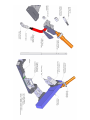
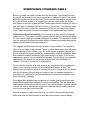
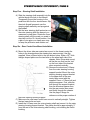
ReSpeed
1979-1985 MAZDA RX7, Non power steering –
Crossmember and Steering Rack conversion:
Component Contents:
1) Powder Coated Crossmember
2) Rear Lower Control Arms (RLCA). Left Hand and Right Hand.
2) Rear Control Arm Mounting Brackets. Left Hand and Right Hand.
2) 1/8th Thick Triangle Plates.
1) Urethane RLCA Bushing Kit.
2) Outer Tie Rod Converters.
1) Engine Mount Bracket with Urethane Isolator.
1) Urethane Rack Bushing / Washer Kit.
1) Lower Steering Shaft with Roll Pin Material and Heat Shrink Sleeve.
1) Lower / Middle Steering Shaft.
1) Outer Steering Housing Support with Aluminum U-Clamp.
1) Round Aluminum Spacer.
2) Flaming River U-joints.
1) Delrin Steering Shaft Bushing.
2) RLCA to LCA Tie Brackets.
1) Rear Control Arm Mounting Bracket Support Bar
Hardware Contents:
5) 10mm x 90mm Bolts, washers and lock nuts.
1) 10mm x 120mm Bolt, washers and lock nuts.
4) 10mm x 90mm Bolts, washer and lock nuts, shipped in the control arm
mounting holes.
2) 3/8-16 x 2 ¼ SHCS, washers and lock nuts
4) 3/8-16 x 1 1/4 Bolts, washers and lock nuts.
2) 1/2-20 x 1 3/4 Bolts, and lock nuts.
2) 5/16-18 x 1 ¼ SHCS and lock nuts
2) 3/4-16 x 3 1/2 Bolts and washers.
2) 9/16 Jam Nuts.
2) 1/2” Gold Clevis with 5/8 Jam Nuts.
2) 5/16” Gold Clevis with 3/8” Jam Nuts.
Steering Rack conversion, page 3
Before you begin you need to make sure of a few things. You will need to have
the car off the ground on jack stands as well as to support the front of the engine
while the engine mounts are removed. This should be done with an engine hoist.
If you do not have access to an engine hoist you can a jack under the engine
with a piece of wood to spread the load. Please make sure the method you use is
safe and does not damage the paint or finish of your vehicle. You also may need
to locate a few tools, beyond the normal hand tools you will need a few special
tools. Please review the list on the next page for the specialized tools needed.
Follow these directions carefully. Do not remove an item before this manual
states to do so. The reason is that the process we will take you through will allow
for your current caster and camber settings to be retained. You will need to re-set
your toe settings but without the added burden of caster and camber settings the
alignment after install will be less expensive.
This upgrade will dive deep into major systems of your vehicle. Care should be
taken at every stage of this process. Failure to follow these instructions will cause
serious damage to your vehicle, your self and/or people or property around you.
Do not attempt this process unless you understand the manual completely. Read
this installation manual completely a few times before you begin. If you do not
understand a part of it do not attempt the upgrade. Find a shop in your area that
specializes in the Mazda first generation or at the least the modification of
vehicles. Feel free to contact us for clarifications.
Do not start this process on a daily driver or any vehicle you are not prepared to
have in a non-running condition for an undetermined amount of time. The
process does not take more than a few days for most to complete but you should
plan for unforeseen things to pop up. Length of time for upgrade depends on
your skill level, familiarity of the first generation rx7 and/or tools available, and
most importantly, planning.
We suggest this upgrade to be completed on a vehicle that has an engine and
transmission completely installed in the stock configuration. This will insure the
final location of the engine is that of stock. If your are working on a project vehicle
that has the engine removed we suggest you take the time to install a complete
mock up running gear before you start
We also suggest you ask a friend to help you. Most of the time two heads are
better than one and the extra pair of arms will most certainly come in handy.
Steering Rack conversion, Page 4
Specialized Tools List:
1) Chop saw, Cutting wheel or a Hacksaw will be needed to cut a ¾”
diameter steel shaft to the correct length.
2) Hand Drill and a few drill bits: 1/8th inch and ¼ inch.
3) Sharpie or Paint Pen
4) Factory Service Manual or Haynes Manual. These can be found on the
Internet for down load if you do not have a copy.
5) 12” long piece of metal rod or flat stock, two 1.5” hose clamps
6) Anti-seize
Step One – Supporting The Vehicle:
You will need to support the vehicle on four jack stands as level as possible. You
will also need to support the engine while the engine mount is being swapped for
the new pieces. You can do this with an engine hoist from above and in front of
the vehicle. If you do not have access to an engine hoist you can use a jack
under the oil pan. If you do decide to support with a jack, you should come from
the back of the car forward to support the engine. Remove the two front wheels.
Step Two – Vehicle Preparation:
A) Following the Mazda factory service or a Haynes manual remove the
steering wheel, combination switch and the ignition switch. Making sure
the wheels are pointed straight ahead - mark the end of the inner steering
shaft at the 12 o’clock position.
B) Remove the center link and tie rods. Save the outer tie rods to be re-used
later.
C) Remove the Idler arm from the chassis.
D) Remove the two bolts holding the steering arms to the bottom of the strut
housings.
E) Remove the two bolts that hold the stay rods to the lower control arms.
Remove the bolt that holds the control arms to the crossmember. Note: Do
not remove the front nuts for the stay rods at this time.
F) Mark the passenger side control arm with a sharpie or piece of tape. Save
the control arm / steering arm assemblies to be re-used later.
Step Three – Crossmember / Steering Box
A) Support the engine with the engine hoist or jack. You should simply
support it, do not jack up on the engine. Take a measurement from the
driver side frame rail to the top bolt that holds the engine brace to the front
cover of the engine. Take a measurement from the ground to the same
bolt. Write these measurements in the spaces provided below:
Steering Rack conversion, Page 5
Measurement from the frame rail to top bolt:________________________
Measurement from the ground to the top bolt: ______________________
B) Take a measurement from the splined end of the inner steering shaft to
the start of the outer steering housing. Write this measurement in the
space provided below:
Measurement from the end of the steering shaft to housing: _____________
C) Remove the engine brace and stock crossmember. Save the four nuts and
washers that hold the crossmember to the chassis for re-use later.
D) Remove the four bolts that hold the upper steering housing to the pedal
box under the dash. Save these bolts to be re-used later. Do not remove
the bolts that hold the slotted end of the bracket to the pedal box.
E) Remove the three bolts that hold the steering box to the chassis. Carefully
slide the steering assembly out the front of the vehicle.
Step Four – Steering Shaft Preparation
A) We have found the outer steering shaft collapsible split joint to be weak.
We suggest to use a piece of metal and two hose clamps to tie the two
halves together until the steering shaft is ready to go back in.
B) Using the factory service manual slide the outer steering housing from the
end of the steering box.
C) Remove the upper inner steering shaft from the lower inner steering shaft.
You will find these two pieces held together with melted plastic. Use a
1/8th drill bit in each end of the two holes to remove the plastic that is
melted into the holes. Be careful to not enlarge the holes larger than 1/8th
inch. You will only need to drill down 1/8th inch or so from each end as the
holes do not go all the way through the lower steering shaft.
D) Slide the supplied new lower inner steering shaft into the stock upper inner
steering shaft until the two holes align. Make sure the 1/8th drill bit will fit
through both holes. Using the supplied aluminum rod cut two pins 1/8th
inch longer than the length of the two holes. Lay the inner steering shaft
assembly on a table using a few spacers to space it up off the table 1/16th
inch. Slide the pins into the two holes so they protrude through both sides
by 1/16th inch. Lightly mushroom the ends of the pins by hitting them with
a hammer. Rotate the inner steering shaft over and lay it directly on the
bench and do the same to the other end of each pin.
E) Slide the supplied heat shrink tube over the inner steering shafts to cover
the two pins. Let the shrink tube hang over the split joint 1/8th to 1/4 inch.
Shrink the tube with a heat gun or hair dryer.
F) Slide the inner steering shaft in the outer steering housing. Slide the
supplied Delrin Steering Shaft Bushing into the outer steering housing. It
may be necessary to clean the inside of the tube with a piece of sand
paper for a proper fitment.
Steering Rack conversion, Page 6
Step Five – Steering Shaft Installation
A) Slide the steering shaft assembly into the
vehicle though the hole in the firewall.
Temporarily mount the housing to the
pedal box with the four stock screws. Slip
the stock firewall grommet over the
steering shaft assembly and up against
the firewall.
B) Set the inner steering shaft protrusion out
the outer steering shaft the amount you
measured in step three. Rotate the inner
steering shaft until the mark you made in
step two is at the 12 o’clock position. Use
a pair of vise grips or a clamp as a stop
to keep the protrusion and rotation set.
Step Six – Rear Control Arm Mount installation
A) Mount the driver side rear control arm mount to the chassis using the
holes in the chassis where the steering box was mounted. Use two
supplied 10mm x 90mm bolts in the two bottom holes. Slide a 1/8th thick
triangle shaped plate over the two bolts on the wheel well side of the
chassis. Note: Driver side mount
will be the one that has the “ear”
on the front side of the bracket
when mounted vertically.
B) Remove the aluminum U-Clamp
from the outer steering housing
support bracket. Mount the outer
steering housing support bracket
to the upper hole in the rear
control arm mount with the
supplied 10mm x 110mm bolt and
aluminum spacer. First, slide the
bolt through the support bracket,
then the aluminum spacer then
into the rear control arm mount
and finally through the chassis.
Use the page 2 image for
reference on the proper rotation of
the outer steering housing support.
C) Make sure the rear lower control arm mount is vertically straight. Tighten
the two lower bolts and nuts.
D) Install the U-Clamp over the outer steering shaft and secure it to the outer
steering housing support bracket. The clamp should be approximately ½”
from the end of the outer steering shaft housing, not including the Delrin
bushing.
Steering Rack conversion, Page 7
E) Tighten the upper nut and bolt for the rear control arm mount / steering
housing support bracket.
F) Follow sections A, B, C and E above to mount the passenger side rear
control arm mount.
G) Tighten the hardware holding the steering assembly to the pedal box.
Step Seven – Rear Control Arm Installation / Caster setup
A) Insert the Urethane RLCA Bushing Kit into the RLCAs following the
instructions in the package from Energy Suspension.
B) Using the supplied 10mm bolts, washers and nuts mount the driver side
and passenger side RLCAs into the rear control arm mounts. The supplied
10mm bolts are shipped inserted into the stock geometry mounting holes.
Only these holes should be used during this installation. Driver side RLCA
is marked.
C) In order to make sure the current caster setting is retained we will use the
stock stay rods to set the rear control arm lengths. Temporarily mount the
RLCA to LCA Tie Brackets to the stock stay rods using the supplied
hardware. They will point to the back of the vehicle and toward the middle.
D) Rotate the rear control arm up and screw in or out on the gold clevis until
the hole in it and the RLCA to LCA Tie Bracket align. Run the jam nut
against the rear control arm. The rear control arms are now set to the
caster setting you began with.
E) Remove the two bolts that temporarily held the RLCA to LCA Tie Brackets
to the stock stay rods. Remove the stock stay rods.
Step Eight - Crossmember Installation
A) Install the new crossmember onto the chassis with the factory nuts and
washers.
B) The stock lower control arms will be mounted on opposite sides of the
vehicle than stock. Meaning the passenger side lower control arm you
marked in step two will now be mounted to the driver side. This will have
the stock steering arms pointing to the front of the vehicle.
C) Install the stock lower control arms using the supplied 10mm bolts and
nuts. The bolts are shipped installed in the stock geometry mounting
holes. Only these holes
should be used during this
installation.
D) Install the two bolts that
hold the steering arms to
the bottom of the strut
housings.
E) Install the RLCA to LCA
Tie Brackets to the stock
lower control arms where
the stay rods mounted.
F) Install the supplied ½”
hardware though the gold clevis and RLCA to LCA Tie Brackets.
Steering Rack conversion, Page 8
G) Install the engine mount to the front of the engine using the factory
mounting hardware. Using the supplied 3/8” socket head cap screws up
from the bottom of the slots in the crossmember through the supplied
urethane isolator into the slots in the engine mount.
H) Drop the jack or engine hoist slightly to allow the engine to sit on the
urethane isolator. Check the measurements you took in Step Three. You
can slide the engine from left to right a bit to obtain the frame rail
measurement. There is a small tolerance on these measurements.
I) Once the engine is positioned where you want it, tighten the hardware.
Step Nine – Rack Prep and Mounting
A) The flaming river rack will need to be modified slightly for use with the kit.
Screw the supplied 9/16” jam nuts all the way down on the rack tie rod
threads. Measure back 1.5” from where the jam nut stops and cut the
extra with a hacksaw or cutting wheel. Debur the ends. Apply anti-seize to
the threads.
B) Thread on the Outer Tie Rod Converters. Apply anti-seize to the threads.
Thread the stock outer tie rods to the Outer Tie Rod Converters - these
are left hand threaded.
C) Slide the supplied urethane rack bushings in to the rack mounting holes.
D) Mount the rack to the crossmember with the supplied ¾” bolts and
washers. There should be a washer on each side of the urethane
bushings.
E) Mount the tie rods to the steering arms using new cotter keys.
F) Center the rack by twisting the splined steering rack shaft and measuring
the amount the tie rod ends protrude from the inner fender well of the
vehicle. You need to make sure the tie rods and tie rod converters are
threaded all the way down on the threads to obtain an accurate
measurement.
G) Temporally mount the supplied Flaming River u-joint to the splines on the
steering rack shaft. You will notice a groove cut into the rack shaft. This is
where the setscrew in the u-joint will rest. Make 100% you seat the
setscrew into the groove.
H) Temporarily mount the other flaming river u-joint 7/8” onto the inner lower
steering shaft with a supplied setscrew. You must make 100% on the 7/8”
measurement. Not enough shaft into the u-joint is unsafe and to much will
cause the u-joints to bind.
I) Measure the distance from the end of each u-joint to each other. It may be
easier to have someone help you do this. Take this measurement and add
1.75”. Take the total measurements and cut the supplied ¾” DD middle
shaft to this length. Example: 6.125” measurement + 1.750 = 7.875”
J) Install the cut shaft between the two u-joints. It will be necessary to loosen
the setscrews on the u-joints and side them further onto the shafts to gain
enough room the get the middle shaft installed.
K) Make sure the u-joints are installed back in place, 7/8” from the ends of
each shaft. Hold them in place with one setscrew each. Visually inspect
for shaft protrusion to far into the u-joints. Temporarily install the steering
wheel. Turn the steering wheel lock to lock and inspect for binding.
Steering Rack conversion, Page 9
L) Remove the steering wheel. Check to make sure the end of the inner
steering shaft is protruding the measurement taken in step three. Make
sure the mark made on the end of the inner steering shaft is still at 12
o’clock position.
M) Once you are satisfied with the operation of the steering shaft follow the
instructions on the back of the Flaming River u-joint packages for final
setting of the setscrews and jam nuts. Double-check all of your work in
this area.
Step Ten – Support Bar Installation
A) Put a small amount of Anti-seize on the gold clevis installed into the
support bar. Thread the clevis all the way into the support bar.
B) Install the support tube clevis onto the passenger side rear control arm
mount “Ear”.
C) Adjust the clevis until the centerline distance matches that of the ears by
twisting the support bar and holding the driver side clevis from turning.
D) Insert the 5/16” hardware and tighten.
Step Eleven – Final Assembly
A) Reinstall the parts removed in Section A of Step Two.
B) Double check all nuts and bolts installed during assembly of all steps.
C) Run the steering from lock to lock and check for binding or excess
shaft movements.
D) The toe settings will need to be re-set. These can be done by eye to
make it down the road a few miles but must be properly set in order for the
vehicle to handle properly. Improper toes settings will also wear tires
faster.
One you have completed the assembly It is important to
doubledouble-check all your work. It is important to revisit the
installation after a few miles of driving and then
then daily until
you are comfortable the system is operating 100% and the
hardware is not loosening.
Step Twelve – Adjustments
The extra holes in the crossmember allow for adjustments in camber, and roll
center. With the use of a different hole in the rear mounts than the front mounts
you can begin to experiment with caster and/or camber gains. The gold clevis will
now be used for caster settings.
Optional parts for the kit are rod end conversions for the outer tie rods, Aluminum
engine mount isolators, as well as offset rack bushings that can be used for
bump steer adjustments on heavily lowered race vehicles.