1
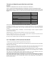
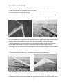
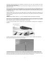
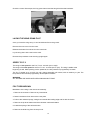
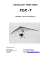
NANOLIGHT TRIKE WING FOX -T OWNER / SERVICE MANUAL Manufactured by: AEROS Ltd. Post-Volynskaya St. 5 Kiev 03061 Ukraine Tel: (380 44) 4554120 Fax: (380 44) 4554116 E-mail: [email protected], http:// www.aeros.com.ua 1 2 Table of Contents Technical Information and Operating Limitations .......................................................... 5 Fox T Reassembly After Shipping Procedure……………………………………................ 5 Fox T Breakdown For Shipping Procedure…………………......………………………........ 6 Fox T Set-Up Procedure ................................................................................................... 7 Preflight Procedure…………………………………………………………………………… 10 Laying the Wing Down Flat…………………………………………………………………. 12 Speed to Fly ..………………………………………………………………………………….. 12 Fox T Breakdown .......................................................................................................... .…12 Wing Tuning ……………………………………………………………………………………… 13 Maintenance.…………………………………………………………………………………….. 14 In Closing - A Few Final Words on Your Safety................................................................ 17 Schemes 3 Thank you for purchasing an Aeros wing for your nanolight trike. The Fox T wing is the best choice for those who want to feel the simplicity and real pleasure of bird-like flying with a nanolight trike. Slow, low and maneuverable flying is great fun when you fly the Fox T. It will allow you to float in the sky with maximum level of safety. With this wing you will have an extremely pleasurable flying experience. Please read and be sure you thoroughly understand this manual before flying the Fox T. Be sure that you thoroughly familiar with the wing and the contents of this manual before initial operation. We encourage you to read this manual thoroughly for information on the proper use and maintenance of your Aeros wing. If you have access to the Internet, please visit us regularly at http://www.aeros.com.ua In case of any doubts or questions contact your local dealers or Aeros directly. We wish you safe and enjoyable flying career. Aeros Ltd. Definitions Definitions used in this Manual such as WARNING, CAUTION and NOTE are employed in the following context: WARNING OPERATING PROCEDURES, TECHNIQUES, ETC. WHICH IF NOT FOLLOWED CORRECTLY, MAY RESULT IN PERSONAL INJURY OR DEATH. CAUTION OPERATING PROCEDURES, TECHNIQUES, ETC. WHICH IF NOT STRICTLY OBSERVED, MAY RESULT IN DAMAGE TO THE AIRCRAFT OR ITS INSTALLED EQUIPMENT. NOTE Operating procedures, techniques, etc. which considered essential to highlight. 4 TECHNICAL INFORMATION AND OPERATING LIMITATIONS WARNING THE FOX T IS DESIGNED FOR FLYING WITH A NANOLIGHT TRIKE ONLY. The Fox T wing has been designed especially for nanolight trikes, using a Fox hang glider as a base. Flight operation of the Fox T should be limited to non-aerobatic maneuvers; those in which the pitch angle will not exceed 30 degrees nose up or nose down from the horizon and bank angle will not exceed 60 degrees. 16.2 (174) 9.6 (31.5) 5.7 120 24 (53) 14 5.8/3.9/2.2 +6/-3 8 (18) 32 (20) 75 (47) 104 (230) 154 (340) Sail area, sq.m. (sq.ft.) Wing span, m (ft.) Aspect ratio Nose angle, Weight (without bags), kg (lb) Number of sail battens Breakdown length, m (ft) Tested load, G Wind speed max, m/sec (mph) Min. airspeed, km/h (mph) Max. airspeed, km/h (mph) Min. clip-in weight, kg (lb) Max. clip-in weight, kg (lb) Aeros recommends that no attempt should ever be made to deliberately spin this wing. The stability, controllability, and structural strength of a properly maintained Fox T have been determined to be adequate for safe operation when the wing is operated within the entire manufacturer specified limitations. No warranty of adequate stability, controllability, or structural strength is made or implied for operation outside of these limitations. Operating the Fox T outside of the above limitations may result in injury and death. Flying a nanolight trike with the Fox T wing in strong or gusty winds or turbulence may result in loss of control of the wing, which may lead to injury and death. Do not fly in such conditions unless you realize and wish to personally accept the associated risks. FOX T REASSEMBLY AFTER SHIPPING PROCEDURE 1. With the wing in the bag (4 meters long) lay the wing on the ground. 2. Unzip the bag. Undo the Velcro straps. Remove the batten bag, the control bar and the outer leading edge tubes # 3 from the bag. 3. Unfold the sail along the leading edge to its full length. Attach the outer leading edge tubes # 3 to the front leading edge tubes # 2 according to the markings (L-left, R-right marks must be on top). Working on one wing at a time and working with the appropriate leading edge # 3, fold the outer sprog, which is attached to the outer leading edge, towards the inboard end of the leading tube # 3. Slide the inboard end of the leading edge tube # 3 into the sail. Then slide the outer leading edge forward, allowing the sprog end to come outside the sail at the corresponding hole, and slide the rear leading edge into the inner leading edge. Align the outer leading edge properly so that the sprog is on the inside of the leading edge, and slide the outer leading edge forward, rotating as necessary, until the slot in the outer leading edge engages securely into the clevis pin in the front leading edge. When the outer leading edge is fully engaged, you will not be able to rotate it. 5 4. Tighten the sail along the leading edge by putting the sail mount webbing into the slot in the end cap of the leading edge # 3. NOTE The sail mount screws on the front part of the leading edge tubes # 1 must be unscrewed, otherwise the excess sail tension will not allow tightening the sail. The sail mount screws have to be screwed back after you accomplish all steps in section “Fox T set-up procedure” from item 1 through item 9. 5. Secure the sail mount webbing to the leading edge # 3 with the sail mount webbing Velcro. NOTE When spreading the wings with the sail mount screws having been unscrewed check that the sail mount webbing is in proper position in the slot of the end cap of the leading edge # 3. 6. Install the wing tip bags. Put battens on top of the wing between Mylar pockets in the front part of the wing. Place Velcro ties around the wing. Put the speed bar between leading edges in the rear part of the wing. Put the wing bag back on and zip it up. FOX T BREAKDOWN FOR SHIPPING PROCEDURE This process will basically be the reverse of reassembling after breakdown for shipping. Before beginning, read through the section above on how to re-install the rear leading edges. 1. Lay the wing on the ground or floor, unzip the bag and remove the Velcro ties. Remove the speed bar and battens from the wing. Remove the protection wing tip bags. 2. Check to see that the leading edges are marked “Left” and “Right”. If they are not, mark them with an indelible marker. 3. Unscrew the sail mount screws from the leading edges # 1. 4. Undo the sail mount webbing Velcro and remove the sail mount webbing from the leading edges end caps. With the outboard sprog folded towards the nose pull the rear leading edge straight aft and slide it backwards carefully out of the sail. Tape or pad the exposed ends of the inner leading edge tubes # 3, and do the same for the outer leading edge tubes # 2 in order to prevent sail damage during transportation. 5. Carefully fold the outermost area of the sail over onto the innermost area of the sail, place Velcro ties around the wing and put on the wing bag, turning the bag 180 deg (i.e. matching the front part of the bag to the rear part of the wing). 6. Zip up the wing bag zipper. 6 FOX T SET-UP PROCEDURE 1. Lay the wing on the ground, with the bag zipper up and the nose of the wing pointing into the wind. 2. Undo zipper and take out the battens and the control bar. 3. Lift and separate the control frame uprights. Remove the quick pin from the corner bracket. Insert the corner bracket all the way into the control bar. Install the quick pin bolt (from front to rear), securing the bracket to the control bar. . CAUTION DO NOT FORCE THE FITTING INTO THE CONTROL BAR IF IT DOES NOT SLIDE IN FREELY AND CHECK FOR DIRT OR DAMAGE TO THE FITTING OR THE INSIDE OF THE CONTROL BAR. 4. Flip the wing upright on the control bar. Try to set the control bar on level ground. Remove the wing bag and all the Velcro sail ties. Do not remove the leading edge tip protection bags at this time. 5. By lifting up the nose batten, push the nose batten fully back into the sail so that the V-tip of the batten rests on top of the keel tube. 6. Spread the wings almost all the way. The kingpost will automatically rise half way up. When spreading the wings make sure the washout bridles are not twisted or tangled around the bridle carabiner. 7. Remove the battens from the batten bag, and check each batten for symmetry against the corresponding batten from the other wing. Align the battens at their front tips, and at about the 60% of the 7 chord point. There should not be any deviation of more than 3 mm (1/8’’) from one batten to the other along the full length of the battens. If you choose not to check your battens for symmetry before each flight, you should, at a minimum, check them once a month. Aeros convention is that the red marked battens go in the left (port) wing and green marked battens in the right (starboard) wing. Battens are numbered from the center outwards, and the longest batten in a Fox T is designated as the "No. 1" batten. Install the cambered battens in the sail, leaving out the shortest three on each side for now. Install the batten tips into the hem of the trailing edge. At each batten, make sure the opening in the underside of the trailing edge hem is spread to accept the tab on the batten tip. Make sure the tab slides fully into the hem. CAUTION INSERT THE BATTENS CAREFULLY, SO AS TO MINIMISE STRESS AND WEAR ON THE SAIL. Never insert or remove battens with the crosstube tensioned (except for up to the last three on each side) and never insert or remove battens with heavy wind pressure on the top of the sail or in any condition which causes the battens to slide with great resistance in the pockets. To open or close the batten tip lever, press firmly on the undersurface of the tip lever to disengage or engage it. 8. Attach the bridle ring to the snap hook, taking care that there is no twist or rotation in the bridle ring which causes the bridle lines to cross over one another. 9. Spread the wings all the way and check all cables for any twisted thimbles or tangled cables. At the rear inside of the keel pocket find the sweep (crosstube tensioning) wires handle. Pull the sweep wires handle out of the rear end of the keel pocket, and check that the sweep wires are not wrapped around the keel. Attach the shackle of the sweep wires to the hook, placed on the keel tube. 8 WARNING IN-FLIGHT DISENGAGEMENT OF THIS ATTACHMENT WILL CAUSE A COMPLETE LOSS OF STRUCTURAL SUPPORT OF THE WING AND A TOTAL LOSS OF CONTROL. NEVER ATTACH THE PULL HANDLE WEBBING OF THE SHACKLE TO THE HOOK, EVEN TEMPORARILY. 10. Install the last three cambered outboard top surface battens. Install the tip lever battens as shown on the photos. 11. The next step is to install the outboard sprogs. To do so swing the sprog away from the leading edge and push it towards the leading edge in to the receptacle. Make sure the sprog sits all the way in the sprog receptacle. 12. Attach the bottom front wires to the hook on the bottom nose plate. 13. Install the nosecone, which is attached to the front part of the keel tube. Now your wing is ready to be mounted on your nanolight trike. 9 WARNING DO NOT FLY WITHOUT THE NOSECONE! PREFLIGHT PROCEDURE Conduct a complete preflight inspection of the wing, checking all assemblies, which have not already been checked. Every bolt, nut, pin, safety ring, and fastener of any kind should be checked during every pre-flight. A full pre-flight inspection should precede every flight you make, not just the first flight of the day. Carefully check the entire length of the leading edge pocket to insure that the Mylar insert is lying flat in the pocket. If any section of the Mylar is folded under, de-tension the crossbar, remove as many battens as necessary and unfold the Mylar. Along the left leading edge: Open the crossbar junction access zipper and look inside, making sure that side wires are properly secured, that the thimbles are not cocked on the tang. Check the split pin and the nut, which secures the leading edge – crossbar junction. Check that the sail is not caught on the crossbar end, or on any of the hardware. At the left wingtip: Check that the tip lever batten is properly installed. Along the trailing edge, left wing Check that there are no tears in the sail material along the trailing edge Check that all battens are properly secured Check that the outboard sprog is properly secured in position supporting the last outboard cambered batten. Check that the washout bridles are properly engaged. 10 From the rear keel Check that the shackle of the sweep wires is secured on the hook on the keel tube. Check the nuts of the kingpost channel, which secures the channel to the keel. Check the safety ring and the clevis pin, which secures the kingpost to the channel. Check the kingpost top for proper attachment of the bridles and condition of the top rear wire, carabiner and bridle wires. Along the trailing edge, right wing: Same as for the left wing. At the right tip: Same as for the left tip. Along the right leading edge: Same as for the left leading edge. Under the wing at the control bar: Sight down the downtubes, making sure that they are straight. WARNING DO NOT FLY WITH BENT DOWNTUBES! Check the cables at the control bar corners, making sure there are no kinks or twisted thimbles. Check for proper installation of all nuts and safety rings at the control bar corners. Check the sweep wire for wear where it passes through the kingpost channel. Check the crossbar center plate’s assembly including the sweep wires/X-bar junction and the center bolt. Also, visually inspect the crosstubes by sighting along the length of the crosstubes looking for any evidence of damage. 11 Check the control frame apex, the king post channel and the hang block bracket hardware. LAYING THE WING DOWN FLAT Once you have the wing set up, it can be laid down flat on the ground. Remove the nose cone from the nose. Release the bottom front wires from the nose hook. Lay the wing down with nose into the wind. Reverse the procedure to set the wing upright again. SPEED TO FLY The range of trim speed for the Fox T is 45 - 50 km/h (28-31 mph). The range of the stall speed for the Fox T is 32 - 34 km/h (20-21 mph). The wing is stable at the beginning of stall. While pushing out the speed bar, the bar pressure is progressively increase. The Fox T speeds up to 75 km/h (47 mph), being essentially roll neutral, with no tendency to yaw. The bar pressure will increase progressively as the speed increases. WARNING ALL SPEEDS ARE GIVEN WITH AEROS NANOLIGHT TRIKE. FOX T BREAKDOWN Breakdown of the wing is the reverse of assembly. 1. Remove the nosecone. Remove any instruments. 2. Detach the bottom front wires at the nose plate. 3. Pull out the outboard sprogs, swing them towards the leading edge and fix with the Velcro. 4. Remove the tip lever battens and three shortest cambered battens. 5. Install the tip bag of the sail at this time. 6. Remove the bridle ring from the snap hook. 12 7. De-tension the crossbar sweep wires and let the wings fold in slightly. 8. Remove the remaining top surface battens. 9. Fold the wings all the way in to the keel pulling the sail over the top of the leading edges. At each wingtip, remove the tip cover bag. Lay the kingpost down forward against the keel. Install the protective pad and sock over the rear wires junction bolt and the rear end of the keel. 10. Pull the sail out away from the keel until it is even on top and bottom. Roll the sail gently and carefully, parallel to the trailing edge of the front and then outboard portion of the sail. NOTE Try to roll the sail in such a way that the leading edge portion remains as smooth as possible. Do not attempt to stuff the sail between the Mylar pocket and the leading edge tube at any point where you feel resistance, and do not attach the Velcro ties tight so as to induce creases in the Mylar or leading edge sail material. Working from the trailing edge, roll the sail tightly to the leading edge and install the wing tip cover bag. 11. Finish rolling the sail in the area of the sprogs. Secure the sail with the Velcro sail ties. 12. Stow the battens in the batten bag and stow it in the front part of the wing. 13. Install the sail velcroes around the sail and stow the nosecone under the most forward Velcro. 14. Install the wing bag. Flip the wing over onto the ground. Detach the control bar. Fit the control bar in the protection bag and stow it between the leading edges in the aft part of the wing. 15. Fold up the control frame and install the control frame bag, lay it down against the keel. 16. Zip up the wing bag. WING TUNING Properly tuned, the wing is safe, comfortable and fun to fly. The wing has been tested and tuned by the manufacture or your dealer. However, in case you have enough experience, you may tune the wing by yourself, as written below, if necessary. There are a number of adjustments that affect the flight characteristics. WARNING DO NOT PERFORM MORE THAN ONE ADJUSTMENT AT ONCE. IF YOU DO NOT HAVE ENOUGH EXPERIENCE TO TEST FLY THE WING, ASK MORE EXPERIENCED PILOT TO DO IT FOR YOU. IT SHOULD BE PERFORMED IN SMOOTN AIR AND WITH CAUTION. BATTENS The battens will need to be compared and adjusted to match the batten profile template at regular intervals. Small variations in batten camber (± 10 mm at the trailing edge) will not have significant effect on flight characteristics. BATTENS TENSION With some airtime on the wing the battens tension may get too loose, this may cause the trailing edge to flatter. If the battens tensioned too much, the handling will become harder. Make sure the battens tensioned on both wings identical. All battens on the Fox T are tensioned by lever batten tips. The desired batten tension can be easily adjusted by the threaded batten tip adjuster. To increase batten tension rotate the threaded lever batten tip adjuster counter clockwise. To decrease batten tension rotate the threaded lever batten tip adjuster clockwise. 13 SAIL MOUNT CAPS ADJUSTMENT The turn of the wing can be corrected by rotating one of the sail mount plastic caps. A left turn is corrected by twisting the right sail cap clockwise (twisting the sail up at the trailing edge). A right turn is corrected by twisting the left sail mount cap counter clockwise (twisting the sail up at the trailing edge). If rotation of the plastic cap on one side is not enough to compensate turn, you can at the same time rotate the plastic cap on another wing in opposite direction. CG ADJUSTMENT CG adjustment is done by changing the location of your hang point along the keel. The farther forward your hang point is, the faster the wing will trim, the less effort will be required to fly fast, and the more effort will be required to fly slow. On the Fox T, the hang point position is adjusted by repositioning the hang bracket along the keel tube. MAINTENANCE This section contains a recommended schedule of periodic maintenance. None of the items in this section are a substitute for the continual and consistent practice of proper pre-flight inspections and immediate maintenance of any items on the wing, which require it. Safety requires that your wing be fully airworthy for every flight. Nuts and bolts must always be secure, safety rings must always be in place, and damage to any part, which could compromise the airworthiness of the wing, cannot be tolerated. If you have a question about the need to repair or replace some part of your wing, feel free to contact your dealer or Aeros directly. It is not always obvious which items require attention and which may not. Minor dents or dings in a non-critical location on an airframe tube may not require any repair or maintenance. On the other hand, a wire that has been kinked one time can fail very quickly after that, and should be replaced immediately. We recommend that you have all maintenance work done by your Aeros dealer. EVERY SIX MONTHS 1. Check the sail washout as described in the last section. 2. Check your battens on a flat level floor against the batten diagram provided, and correct any that deviate from the pattern by more than 6 mm (1/4"). 3. If you fly in a dusty or sandy environment, it will help to prolong the life of your batten pockets if you wipe each batten with a rag before you install it in the sail. 4. Have a complete inspection performed on the wing and replace any suspension system component that shows any wear, and any cable that shows any kinks, wear, damage, corrosion, etc. 14 5. Inspect all bolts for tightness, all safety rings for proper installation and possible damage. Inspect plates and fittings for damage, holes in tubes for elongation. 6. Inspect the sail for wear, tears, UV damage, loose stitching, etc. 7. Lightly spray all zippers on the wing with silicone spray lubricant. Also spray your battens before you install them in the wing to lubricate the insides of the batten pockets. Do not use any other type of lubricant. Wipe off any excess silicone so that it does not attract dirt. 8. Inspect the outboard sprogs. If the sprogs have been loaded heavily, it is possible that the sprog tubes may have been bent. EVERY YEAR In addition to the normal six month service items, also perform the following: 1. Have the sail completely removed from the frame and disassemble all frame components. Inspect every part of the wing for any damage or wear. Inspect the tubes for straightness and for signs of corrosion. 2. Anytime you have the sail off the frame, inspect all of the batten pockets and batten pocket terminations. 3. Replace bottom side wires and hang block heart bolt. SPECIAL CIRCUMSTANCES 1. Any time you suffer a crash or extremely heavy landing you should have an “annual” inspection done on your wing to insure that you find all damaged parts. Heavy landings may also impose very high loads on the sprogs and bridle lines. Inspect them accordingly. 2. If your wing is ever exposed to salt water you will need to have the wing completely disassembled in accordance with the recommended annual inspection procedure. All frame parts will need to be disassembled, including the removal of all sleeves and bushings, flushed liberally with fresh water and dried completely. 3. A wet wing must be dried before storing. Do not leave your wing wet for more than one day, because corrosion may result. 4. Take special care to avoid ice-covering the wing, particularly the leading edge in wintertime. 5. If you fly regularly at the coast in windy conditions, be aware that the sea mist spray can have the same effect. Hose down your wing after such flights, and keep a special lookout for corrosion. 6. Keeping your sail clean will extend the life of the cloth. When cleaning the entire sail you should generally use only water and a soft brush. You may clean small spots or stains with any commercial spot remover that is labeled for use on polyester. A NOTE ABOUT CABLES AND CABLE MAINTENANCE The cables which support the wing’s airframe are critical components of the wing’s structure, and must be maintained in an airworthy condition. It is a general practice in the design of aircraft structures to design to an ultimate strength of 1.5 times the highest expected load in normal service. The wing’s cables, like other structural components on the wing, are typically designed with a structural safety factor of only about 50% above the expected maximum load. No significant loss in cable strength can be tolerated. 15 A cable with even a single broken strand must be replaced before the wing is flown again. A cable which has been bent sharply enough to have taken a permanent set must also be replaced immediately. Some degree of fatigue due to repeated bending of cables is almost unavoidable in an aircraft that is assembled and disassembled regularly. Bottom side wires are subject to the highest loads in flight, and are therefore the most critical. This is why we recommend that these wires be replaced annually, even if there is no known damage. CHECKING THE SAIL WASHOUT 1. Fully set up the wing on a reasonably level surface. 2. Place three equal supports, about 1,7 m (5.5 ft) tall, under the each leading edge tube-cross tube junction and in place behind the connection of rear bottom cables to the keel tube. 3. Tie a lightweight string tightly across the wing from the inner of the supported battens to the corresponding batten on the other wing. 4. Measure the height of each thread in relation to the top of the keel tube. The results should be as follows: Batten number 1–1 2–2 3–3 6 -6 Sail height above the keel tube, mm 258 375 359 335 If measured distances are less than those of written in the table above, the wing should not be flown until re-adjusted. Tolerance is ± 20 mm. If measured distances are differ from those of written in the table for 20 mm per side, the wing should not be flown. In such case consult your local dealer. 16 IN CLOSING - A FEW FINAL WORDS ON YOUR SAFETY - Flying nanolight trikes is a grate fun but it is, as any form of flying, associated with risks. Your safety can be greatly enhanced by following a few simple rules: - Your wing is delivered to you ready to fly. Do not make any adjustments, which are not described in this manual. - If you are in doubt about any aspect of your wing, you should consult your dealer or Aeros for advice. - Fly a wing suited to your level of ability. A new risk may arise when you first fly a new type of the wing. - The reactions of your new wing may well differ from those of the wing you where used to. In order to keep this risk low, we recommend that you gradually become familiar with your new wing. - Before every take-off always do both an assembly check and a pre-flight check of your wing and a trike unit. - Do not take off if the sail is wet, especially the leading edge, as the stall speed will increase significantly. - Always fly with a dry sail! - A wet wing must be dried before storing. Do not leave your wing wet for more than one day because corrosion may result. - Don’t push your luck; it is your responsibility to know the limits of your wing and the limits of your own experience. Remember that ultimately your safety is your responsibility. - Fly only in places that are suitable for flying. - With proper care and maintenance, your wing will retain a high level of airworthiness for many years. Have fun. Fly safely. Aeros Team 17 Перв. примен. F16T.100.000.AD 15-F16T.650.000.AD 11-F16T.610.000.AD 3-F16.300.001.AD 9-F16T.450.000.AD 13-F16T.630.000.AD D Справ. № 6-F16T.150.000.AD C 17-STD.0344.AS B 7-F16T.250.000.AD A 8-F16T.350.000.AD E I F Инв. № подл. Подпись и дата Взам. инв. № Инв. № дубл. Подпись и дата 2-F16.200.000.AD G 14-F16T.640.000.AD 2-F16.200.000.AD 7-F16T.250.000.AD 10-F16T.600.000.AD 4-F16.300.002.AD 39-F16T.501.000 1-DSC15T.065.000.AD H 12-F16T.620.000.AD F16T.100.000.AD Лит. Изм. Лист № докум. Разраб. Пров. Т.контр. Нач. КБ Н.контр. Утв. F16T.100.000.AD Подп. Дата 07.04.11 Масса Масштаб 1:20 Fox 16T Airframe (Fox 16T Каркас) Лист 1 Листов 8 "AEROS" Копировал Формат А3 A (1 : 1) F16T.100.000.AD Перв. примен. 71-Болт 6-68 ОСТ131120-80 88-Washer M6 (DIN 125) 80-Nut M6, self-locking (DIN 985) Справ. № 55-STL.231.000 Подпись и дата 25-CBT2.14.181.000 49-STL.122.005 Инв. № подл. Подпись и дата Взам. инв. № Инв. № дубл. 25-CBT2.14.181.000 56-STL.232.000 19-STL.237.000.AD 74-Болт 6-76 ОСТ131120-80 88-Washer M6 (DIN 125) 80-Nut M6, self-locking (DIN 985) 27-DSC12B.266.000 88-Washer M6 (DIN 125) 79-Nut M6 (DIN934) 82-Safety Ring SBR1016 Изм. Лист № докум. F16T.100.000.AD Подп. Дата F16T.100.000.AD Копировал Лист 2 Формат А3 Перв. примен. F16T.100.000.AD 57-STL.235.000 B (1 : 1) 80-Nut M6, self-locking (DIN 985) 85-Splint 2.0 x 25 SBS2025 88-Washer M6 (DIN 125) 2 шт 64-Nut M8 ОСТ133042-80 67-Болт 6-34 ОСТ131120-80 89-Washer M8 (DIN 125) 31-DSC14A.265.000 80-Nut M6, self-locking (DIN 985) 88-Washer M6 (DIN 125) 2 шт 66-Болт 6-28 ОСТ131120-80 29-DSC14A.261.000 54-STL.181.000 50-STL.122.015 16-F16T.660.000.AD 28-DSC14A.181.000 5-F16.680.000.AD Инв. № подл. Подпись и дата Взам. инв. № Инв. № дубл. Подпись и дата Справ. № 30-DSC14A.262.000 73-Болт 6-74 ОСТ131120-80 88-Washer M6 (DIN 125) 80-Nut M6, self-locking (DIN 985) 86-Tapping Screw 4.2-16 Изм. Лист № докум. F16T.100.000.AD Подп. Дата 72-Болт 6-69 ОСТ131120-80 88-Washer M6 (DIN 125) 80-Nut M6, self-locking (DIN 985) F16T.100.000.AD Копировал Лист 3 Формат А3 Перв. примен. F16T.100.000.AD D (1 : 1) C (1 : 2) 97-КТu5 80-Nut M6, self-locking (DIN 985) 88-Washer M6 (DIN 125) 75-Болт 6-80 ОСТ131155-80 81-Safety Ring SBR1011 92-AL061-1500 96-HB4-100 34-DSC15T.043.000 31-DSC15T.041.000 Справ. № 53-STL.168.005 33-DSC15T.042.000 35-DSC15T.044.000 Инв. № подл. Подпись и дата Взам. инв. № Инв. № дубл. Подпись и дата 81-Safety Ring SBR1011 78-Nut M6 (DIN 936) 88-Washer M6 (DIN 125) 76-Болт(2) 6-78 ОСТ131120-80 36-DSC15T.045.000 44-STD.0424(C.15.0020.610.000) 45-STD.0502(STUD.0010.510.000) 52-STL.153.005 60-STL.312.000 40-OPT.D.245.000 89-Washer M8 (DIN 125) 2 шт 65-Nut М8 ОСТ 133059-80 Изм. Лист № докум. F16T.100.000.AD 80-Nut M6, self-locking (DIN 985) 88-Washer M6 (DIN 125) 69-Болт 6-66 ОСТ131120-80 Подп. Дата F16T.100.000.AD Копировал Лист 4 Формат А3 F16T.100.000.AD Перв. примен. E (1 : 1) 19-STL.237.000.AD 80-Nut M6, self-locking (DIN 985) 88-Washer M6 (DIN 125) 24-CBT09.13.236.000 59-STL.251.000 80-Nut M6, self-locking (DIN 985) 88-Washer M6 (DIN 125) 58-STL.236.003 89-Washer M8 (DIN 125) Справ. № 80-Nut M6, self-locking (DIN 985) 88-Washer M6 (DIN 125) 70-Болт 6-67 ОСТ131120-80 68-Болт 6-36 ОСТ131120-80 20-STL.252.000.AD 88-Washer M6 (DIN 125) Инв. № подл. Подпись и дата Взам. инв. № Инв. № дубл. Подпись и дата 96-HB4-100 80-Nut M6, self-locking (DIN 985) 38-F16T.365.000 88-Washer M6 (DIN 125) 63-Nut M6 ОСТ133042-80 84-Splint 2.0 x 20 SBS2020 Изм. Лист № докум. F16T.100.000.AD Подп. Дата F16T.100.000.AD Копировал Лист 5 Формат А3 F16T.100.000.AD Перв. примен. F (1 : 1) 18-STL.116.000.AD Справ. № 26-DSC12A.260.000 54-STL.181.000 29-DSC14A.261.000 61-STL.521.000 43-STD.0326 Инв. № подл. Подпись и дата Взам. инв. № Инв. № дубл. Подпись и дата 81-Safety Ring SBR1011 69-Болт 6-66 ОСТ131120-80 88-Washer M6 (DIN 125) 80-Nut M6, self-locking (DIN 985) Изм. Лист № докум. F16T.100.000.AD 41-Pin 4х28(26) 48-STG.B.308.000 89-Washer M8 (DIN 125) 64-Nut M8 ОСТ133042-80 85-Splint 2.0 x 25 SBS2025 Подп. Дата F16T.100.000.AD Копировал Лист 6 Формат А3 F16T.100.000.AD Перв. примен. G (1 : 2) 47-STG.B.134.000 Справ. № I (1 : 1) 83-Safety Ring SBR1519 Инв. № дубл. Подпись и дата 17-STD.0344.AS 51-STL.132.000 Инв. № подл. Подпись и дата Взам. инв. № 87-Tapping Screw 4.2x13 91-AL051-500 Изм. Лист № докум. F16T.100.000.AD Подп. Дата F16T.100.000.AD Копировал Лист 7 Формат А3 F16T.100.000.AD Справ. № Перв. примен. H (1 : 2) Подпись и дата 42-STD.0015(C.15.0020.600.007) 88-Washer M6 (DIN 125) 78-Nut M6 (DIN 936) 81-Safety Ring SBR1011 Инв. № подл. Подпись и дата Взам. инв. № Инв. № дубл. 46-STD.0551 23-CBT.166.000 80-Nut M6, self-locking (DIN 985) 94-BE64/33 95-BE65 Изм. Лист № докум. F16T.100.000.AD Подп. Дата 22-CBT.165.000 F16T.100.000.AD Копировал Лист 8 Формат А3 F16T.150.000.AD Перв. примен. Кол. на изделие - 1шт. 2-F16T.152.000.AD Справ. № 3-DSC14B.193.000.AD Инв. № подл. Подпись и дата Взам. инв. № Инв. № дубл. Подпись и дата 1-F16T.151.000.AD F16T.150.000.AD Лит. Поз. 1 Обозначение F16T.151.000.AD Наименование Keel Tube №1 (Килевая труба №1) 2 F16T.152.000.AD Keel Tube №2 (Труба килевая №2) 3 DSC14B.193.000.AD Button Spring One-sided (Фиксатор односторонний ) Изм. Лист № докум. Разраб. Кол. Пров. 1 Т.контр. Нач. КБ 1 Н.контр. 1 Утв. F16T.150.000.AD Подп. Дата 16.12.10 Масса Масштаб 1:2 Keel Tube Assembled (Килевая труба СБ) Лист 1 Листов 1 "AEROS" Копировал Формат А3