1
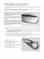
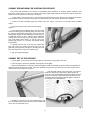
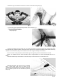
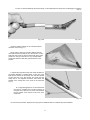
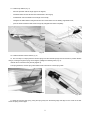
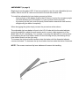
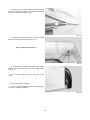
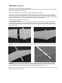
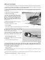
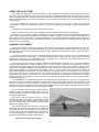
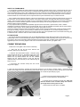
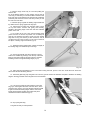
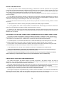
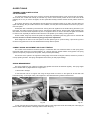
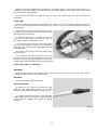
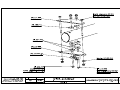
HANG GLIDER
COMBAT-09/COMBAT-09GT
OWNER / SERVICE
MANUAL
Size:__________________
Date of production:
__________________
Serial number:
__________________
Manufactured by:
AEROS Ltd.,
Post-Volynskaya St. 5.,
Kiev, 03061,
UKRAINE
Tel: (380 44) 455 41 20
Fax: (380 44) 455 41 16
E-mail: [email protected], http://www.aeros.com.ua
April 2011 edition
1
Combat Owner / Service Manual
Table of Contens
Introduction....…………………………………………..………….…..………………… 3
Technical information and operating limitations …...................…......……………..
4
Combat reassembly after shipping procedure ...…..................…..……………..…
5
Combat breakdown for shipping procedure.......….…...........…...…...........…..….
6
Combat set-up procedure ...........................…..…..............……................…….…. 6
Preflight procedure…………………………….………….………….…………….……. 11
Laying the glider down flat……………..……….….……………………….….……...
12
Launching and flying the Combat ..................…....................................……......... 13
Aerotowing ..………………………………………….…………………………………. 13
Using the VG system..............................................................................…….......
14
Landing the Combat ..............................................................................….…........ 14
Combat breakdown ................................…..............................................…......... 15
Removing the sail from the airframe and re-installing.........................…..….......... 17
Re-installing the sail on the frame..............……………………….........…..…......... 17
Combat stability systems.......................…..............................................…..........
18
Maintenance..………………..……….………………………………………...……….
19
Glider tuning............................................................…………………………..…….. 21
In closing - a few final words on your safety............................…....…................... 24
SCHEMES………………………………………………………………………………… 25
2
INTRODUCTION
Thank you for purchasing an Aeros glider.
The Combat 09 / Combat 09 GT (hereinafter Combat) hang glider is an advanced product of Aeros Ltd. It is
aimed at improvement of the modern competitive glider with very high performance combined with maximum safety
and comfort.
Please read and be sure you thoroughly understand this manual before flying your Combat. Be sure you are
thoroughly familiar with the set up, break down, preflight and maintenance procedure as described in this manual.
If you have access to the Internet, please visit us regularly at http://www.aeros.com.ua
In case of any doubts or questions contact your local dealers or Aeros.
We wish you a safe and enjoyable flying career.
Aeros Ltd.
3
TECHNICAL INFORMATION AND OPERATING LIMITATIONS
The Combat has been designed for foot launched soaring flight. It has not been designed to be motorized,
tethered, or towed. However it can be towed successfully using proper procedures.
Flight operation of the Combat should be limited to non-aerobatic maneuvers; those in which the pitch angle will
not exceed 30 degrees nose up or nose down from the horizon, and the bank angle will not exceed 60 degrees.
Combat 09/Combat 09GT
Sail area, sq.m.(sq.ft.)
14.9
14.9
(160)
10.7
(35.1)
7.7
129-131
105
(233)
35.8
(79)
24
14.2
14.2
(153)
10.7
(35.1)
8.06
129-131
100
(222)
35.0
(78)
24
13.7
13.7
(145)
10.35
(33.93)
7.9
129-131
90
(200)
34.5
(77)
24
13.5
13.5
(143)
10.7
(35.1)
8.5
129-131
90 -100
(200-222)
35
(78)
24
13.2
13.2
(142)
10.35
(33.93)
8.05
129-131
85
(189)
34.0
(75)
24
12.8
12.8
(138)
10.0
(32.81)
7.8
129-131
75
(166)
33
(73)
24
6
6
6
6
6
6
Tested load, G
Wind speed max, m/sec
(mph)
Min. airspeed with optimal
pilot clip weight, km/h (mph)
4.15/5.9
(13.4/19.3)
+6 / -3
12
(27)
29-31
(18-19)
4.15/5.9
(13.4/19.3)
+6 / -3
12
(27)
29-31
(18-19)
4.1/5.8
(12.8/19)
+6 / -3
12
(27)
29-31
(18-19)
4.15/5.9
(13.4/19.3)
+6 / -3
12
(27)
29-31
(18-19)
4.1/5.8
(12.8/19)
+6 / -3
12
(27)
29-31
(18-19)
4/5.6
(13/18.4)
+6 / -3
12
(27)
29-31
(18-19)
Max. airspeed with optimal
pilot clip weight, km/h (mph)
110+
(69)
110+
(69)
110+
(69)
110+
(69)
110+
(69)
110+
(69)
Min. clip pilot weight, kg (lb)
90
(198)
120
(265)
85
(187)
115
(254)
75
(165)
110
(243)
75
(165)
110
(243)
70
(154)
110
(243)
65
(143)
105
(231)
Wing span, m (ft)
Aspect ratio
Nose angle, º
Pilot clip weight optim., kg
(lb)
Weight (without bags), kg
(lb)
Number of upper sail
battens
Number of bottom sail
battens
Breakdown length, m (ft)
Max. clip pilot weight, kg (lb)
Aeros recommends that no attempt should ever be made to deliberately spin the glider.
The stability, controllability, and structural strength of a properly maintained Combat have been determined to be
adequate for safe operation when the glider is operated within the entire manufacturer specified limitations. No
warranty of adequate stability, controllability, or structural strength is made or implied for operation outside of these
limitations.
Operation of the glider by unqualified pilots may be dangerous.
Operating the Combat outside of the above limitations may result in injury and death. Flying the Combat in the
presence of strong or gusty winds, or turbulence may result in loss of control of the glider, which may lead to injury
and death.
Do not fly in such conditions unless you realize and wish to personally assume the associated risks.
ATTENTION! We do not recommend using Combat for motorized and aerobatic flights.
It requires recommended pilot proficiency not less than pilot rating +40 hours or equivalent Safe Pro rating to
fly Combat.
4
COMBAT REASSEMBLY AFTER SHIPPING PROCEDURE
1. With the glider in the bag (4 meters long) lay the glider on the ground.
2. Unzip the bag. Undo the velcro straps. Remove the batten bag, the speedbar, the rear leading edge tubes # 3 and
winglets from the bag.
3. Unfold the sail along the leading edge to its full length. Attach the rear leading edge tubes # 3 to the front leading
edge tubes # 2 according to the marking (L-left, R-right, marks must be on top).
Working on one wing at a time, and working with the
appropriate leading edge # 3, fold the outer sprog, which
is attached to the rear leading edge, forward against the
rear leading edge. Slide the inboard end of the leading
edge tube # 3 into the sail.
Then slide the rear leading edge forward, allowing
the sprog end to come outside the sail at the access
zipper, and slide the rear leading edge into the front
leading edge.
Align the rear leading edge properly so that the sprog
bracket is on the inside of the leading edge, and slide
the rear leading edge forward, rotating as necessary,
until the button spring in the rear leading edge engages
securely into the holes in the front leading edge. When
the rear leading edge is fully engaged, you will not be
able to rotate it (Fig.1).
Fig. 1
4. Tighten the sail along the leading edge by putting the sail mount webbing into the slot in the end cap of the leading
edge # 3.
Note: the sail mount screws on the front part of the leading edge tubes # 1 must be unscrewed, otherwise the
excess sail tension will not allow tightening the sail.
The sail mount screws have to be screwed back after you accomplish all steps in section “Combat set-up
procedure” from item 1 through item 8.
5. Secure the sail mount webbing to the leading edge # 3 with the sail mount webbing velcro.
Note: When spreading the wings with the sail mount screws been unscrewed check that the sail mount webbing
is in proper position in the slot of the end cap of the leading edge # 3.
6. Install the tip bags.
Put battens on top of the glider between Mylar
pockets in the front part of the glider.
Place velcro ties around the glider.
Put the speedbar and winglets between leading
edges in the rear part of the glider.
Put the glider bag back on and zip it up (Fig.2).
Fig. 2
5
COMBAT BREAKDOWN FOR SHIPPING PROCEDURE
This process will basically be the reverse of reassembling after breakdown for shipping. Before beginning, read
through the section above on how to re-install the rear leading edges. While following the instructions below, refer to the
photos in the section above for reference, if necessary.
1. Lay the glider on the ground or floor, unzip the bag and remove the velcro ties. Remove the speedbar and winglets
from the glider. Remove the protection tip bags. The outboard sprog access zippers should be fully unzipped.
2. Check to see that the leading edges are marked “Left” and “Right”. If they are not, mark them with an indelible
marker.
3. Unscrew the sail mount screws from the leading
edges # 1.
4. Undo the sail mount webbing velcro and remove the
sail mount webbing from the leading edges end caps. With
the outboard sprog folded towards the nose pull the rear
leading edge straight aft while pressing the button spring in
to disengage it from the front, and then slide it backward
carefully out of the sail. Tape or pad the edges of the front
end of the leading edge tubes # 3, and the rear of the
leading edge tubes # 2 to prevent sail damage during
transportation.
5. Carefully fold the rear of the sail over against the
front, place velcro ties around the glider and put on the
glider bag, turning the bag 180 deg (i.e. matching the front
part of the bag to the rear part of the glider) (Fig.3).
6. Zip up the glider bag zipper.
Fig. 3
COMBAT SET-UP PROCEDURE
1. Lay the glider on the ground, with the bag zipper up, with the bag at right angle to the wind.
2. Undo the zipper, remove the speedbar and winglets from the glider.
3. Remove the speedbar from the bag, spread the uprights. Install the speedbar so that the offset of the speedbar is
directed forward in the direction of flight. Attach the speedbar using the quick-pins. Pass the VG-rope through the cleat;
make a knot on the end of the rope (Fig.4).
4. Flip the glider upright on the control bar. Try to set the
basebar on level ground. Remove the glider bag and all
velcro ties. Remove the batten bag with the battens from the
front part of the glider. Spread the wings almost all the way,
so that the sail is a little sagged and the glider is resting on
the wing tips and on the keel tube.
Fig. 4
5. By lifting up and back on the nose batten strings, push
the nose battens fully back into the sail so that the batten tips
rest on top of the keel tube (Fig.5).
Fig. 5
6
6. Attach the ring of the bottom front wires to the hook on the bottom nose plate(Fig.6).
Fig. 6
Fig. 7
7. Turn the hang point spreader bar perpendicular to the keel tube (Fig.7).
Close the central access zipper.
Fix the Velcro straps behind the
hang loop.(Fig.8)
Fig. 8
8. Remove the battens from the batten bag, and check each batten for symmetry against the corresponding batten
from the other wing. Align the battens at the nose, and at about the 60% chord point as shown. There should not be any
deviation of more than 3mm (1/8’’) from one batten to the other along the full length of the battens.
Aeros convention is that green (blue) marked battens go in the right wing and red marked battens in the left.
Battens are numbered from the center outwards, and the longest batten in a Combat is designated as the "# 1"
batten.
Install the cambered top surface battens in the sail, leaving out the shortest four on each side for now.
Install the lever batten tips into the hem of the trailing
edge. At each batten, make sure the opening in the
underside of the trailing edge hem is spread to accept the
tab on the batten tip. Make sure the tab slides fully into the
hem (Fig.9).
7
Fig. 9
To open or close the batten tip lever press firmly on the undersurface of the tip lever to disengage or engage it
(Fig.10).
Fig. 10 a
Fig. 10 b
Insert the battens carefully so as to minimize stress
and wear on the sail (Fig.11).
Never insert or remove top surface battens with the
cross-bar tensioned (except for up to the last four on each
side) and never insert or remove battens with heavy wind
pressure on the top of the sail or in any condition which
causes the battens to slide with great resistance in the
pockets.
Fig. 11
9. Spread the wings all the way and check all cables for
any twisted thimbles or tangled cables. At the rear of the
keel find the shackle of the sweep wire. Pull the shackle
out the rear end of the keel pocket, and check that the
sweep wire is not wrapped around the keel. Attach the
shackle of the sweep wire to the hook on the keel tube
(Fig.12).
An in-flight disengagement of this attachment
will cause a complete loss of structural support of
the glider and a total loss of control. Never attach
the pull handle of the shackle to the hook, even
temporarily.
Fig. 12
10. Remove the protection bags from the wing tips and install the last four outboard top surface battens.
8
11. Install the tip battens (Fig.13):
-
bend the tip batten with the angle approx. 60 degrees;
-
install the batten into the sail with the bend directed to the wing tip;
-
install the flat end of the batten into the angle of the sail tip;
-
straighten the batten little bit and guide another end of the batten onto the leading edge batten hook;
-
push the bend towards the keel section and gently straighten the batten completely.
Fig. 13
Fig. 14
12. Install the bottom surface battens (Fig.14).
13. The next step is to deploy both the inboard sprogs and the outboard sprogs and secure them in position. Before
doing so, working through the sprog access zippers, preflight the following items (Fig.15) :
Internal ribs to confirm that they are fully zipped up.
The sprog hardware, and the sprog cable attachments at both ends of each sprog cable.
Fig. 15 a
Fig. 15 b
To deploy and secure each sprog, swing the sprog away from the leading edge and align it in the center of the rear
end of the sprog access zipper.
9
AMENDMENT (to page 9)
Beginning from the glider # 073.10 we have started to use the new adjustable tip lever
batten, fixed to the LE # 3 with one end and to the sail with another end.
To install the adjustable tip lever batten proceed as follow:
- bend one part of the batten (fixed to the LE tube) in its joint for necessary angle
and slide another part of the batten in it (the one that fixed to the sail);
- by pressing on the joint, push the partly folded batten towards the keel section,
straightening the batten completely.
When de-rigging the glider simply reverse the procedure written above.
The adjustable tip lever batten is fixed to the LE # 3 tube with the threaded adjuster,
giving a possibility to adjust the sail tension and to correct a light asymmetry in the
glider with VG off, if necessary. For example, correcting the light left turn can be done
by increasing the tip lever batten tension on the left wing and (or) decreasing the tip
lever batten tension on the right wing.
To increase the tip lever batten tension rotate the batten with the threaded adjuster
counter clockwise. To decrease the tip lever batten tension rotate the batten clockwise.
NOTE: The excess tensioned tip lever battens will worsen the handling.
Fully close the sprog access zipper and this will secure
the sprog in the proper position underneath the transverse
batten and capture it in position (Fig.16) .
Fig. 16
14. Install the nosecone taking care to align it so that it
lies flat on the top and bottom of the sail (Fig.17) .
Don’t fly without the nosecone!
Fig.17
15. Attach plastic winglets. Put front part of the winglet
between the sail and the outer part of the leading edge
tube (Fig.18) .
Put the winglet tightly inside the sail, fixing it with
velcro.
16. Zip up the center sail zipper.
17. Do a complete preflight inspection of the glider (see
the Section “Preflight procedure”).
Fig. 18
10
AMENDMENT (to page 10)
Combat 09 GT comes with a horizontal stabilizer (tail).
All necessary information regarding the tail is written in the tail Manual. In this section we will provide the information
regarding assembling the glider with a tail.
The horizontal stabilizer (tail) is designed to increase the hang glider pitch stability.
The tail has symmetrical low drag profile and is rigidly mounted at 5 deg. negative angle of attack to the slightly
extended (compare to Combat 09) keel tube. The tail consists of three parts: the center tail section and the left and
the right outer tail sections. It is made of stiff light weight carbon fiber and strong enough to withstand a point loading
and can be easily stored when de-rigged and packed in a glider bag or in a harness bag.
To install the tail on the glider proceed as follows.
1. Set up a glider completely.
2. Take the tail out of the bag. Connect the outer tail sections with the center tail section, installing the spar of the
outer tail first and then the pin at the trailing edge of the outer tail in to the corresponding holes in the center tail.
Make sure that button springs of the outer tail sections spars are fully engage into the holes in the undersurface of
the center tail section.
3. Slide the tail onto the keel tube until the button pins on the keel engages securely into the holes in the center tail
section.
WARNING! THE TAIL SHOULD BE INSTALLED SO THAT ITS DEHIDRAL IS POINTED UP AND ITS SWEEP
POINTED BACKWARD. INSTALLING THE TAIL THE OTHER WAY ARROUND WILL WORSEN THE GLIDER
FLIGHT CHARACTERISTICS AND THE GLIDER WILL BECOME DANGEROUS TO FLY.
NOTE: If there is a slack between the keel and the tail we recommend wrapping the keel around with a tape or sticky
Dacron as shown on the photo above.
PREFLIGHT PROCEDURE
Conduct a complete preflight inspection of the glider, checking all assemblies, which have not already been checked.
Every bolt, nut, pin, safety ring, and fastener of any kind should be checked during every pre-flight. A full pre-flight
inspection should precede every flight you make, not just the first flight of the day.
Carefully check the entire length of the leading edge pocket to insure that the mylar insert is lying flat in the pocket. If
any section of the mylar is folded under, de-tension the crossbar, remove the batten closest to the area of distortion, and
unfold the mylar.
Take your time and inspect entire glider!
Along the left leading edge
Open the main sprog access zipper and look
inside, making sure that the crossbar / leading edge
junction is assembled properly and safely secured
with the nut and the safety ring, side wires are
properly secured between the crossbar and the
leading edge plate, that the thimbles are not cocked
on the tang (Fig.19).
Check that the sail is not caught on the crossbar
end, or on any of the hardware
Remember to close the access zipper.
Fig. 19
At the left wingtip
This procedure is better to perform before plastic winglets have been installed.
Look into the sail from the wing tip. Tip folded batten
must be rested on the batten stop. The washout tip must
be installed. Check for any evidence of dents, deep
scratches, cracks or bends in the LE tube.
Be sure that the sail mount webbing is properly
installed in the end cap slot and safely and correctly
secured with the Velcro around the leading edge (Fig.20).
Along the trailing edge, left wing
Check that there are no tears in the sail material along
the trailing edge.
Check that all battens are properly secured.
Fig. 20
Check that the outboard and inboard sprogs are properly secured in position supporting the transverse battens, and
that the sprog access zippers are properly closed. With the VG set tight, the sprog paddle slides forward on the
transverse batten. Make sure that at VG full tight the rear end of the paddle does not slide past the rear edge of the
transverse batten, or the system could malfunction.
Check that the bridles are properly engaged.
From the rear keel
Check that the sweep wire is tight and secured on the hook on the keel tube. Check the proper alignment of the VG
ropes – they must not be twisted.
Check the rear wires / keel tube junction. The assembly must be connected with the pin and secured with the safety
ring.
Along the trailing edge, right wing:
Same as for the left wing.
11
At the right tip:
Same as for the left tip.
Along the right leading edge:
Same as for the left leading edge.
Under the glider at the control bar:
Sight down the down tubes, making sure that they are straight.
Do not fly with bent down tubes!
Check the cables at the control bar corners, making sure there are no kinks or twisted thimbles. Check for proper
installation of all nuts and safety rings at the control bar corners.
Unzip the center zipper.
Check the sweep wire for wear where it passes around
hang point channel.
Check that the routing of all VG ropes and pulleys is
clear and straight (Fig.21).
Fig. 21
Check the VG operation - the pull should be light initially, becoming harder as the VG tight limit is reached. The return
on release should be smooth.
With the VG set tight, the sprog paddles slides forward on the transverse batten. Make sure that at VG full tight the
rear end of the paddles does not slide past the rear edge of the transverse battens, or the system could malfunction.
Check the crossbar center plates assembly including the sweep wire/X-bar junction, all bolts are in places, secured
with nuts.
Also, visually inspect the crossbar by sighting along the length of the crossbars looking for any evidence of damage.
Check the control bar apex bracket hardware, including the clevis pin safeties, the control bar top plug bolt and nut.
Check the main and backup hang loops, pins and safety rings, bolt and nut, that they are properly installed in the
proper position and that they are in good condition.
LAYING THE GLIDER DOWN FLAT
Once you have the glider set up, it can be laid down flat on the ground.
1. Remove the nose cone from the nose.
2. Release the front wires from the nose hook.
3. Lay the glider down with nose into the wind.
4. Take a keel tube with a hand near the trailing edge and put the keel tube approx. 0.5 m up. Release the sweep
wire from the hook on the keel tube to loose a tension of bottom side wires.
Reverse this procedure to set the glider upright again.
12
LAUNCHING AND FLYING THE COMBAT
Before launching, hook in to the glider and do a careful hang check. We recommend that you hang as close to
the base tube as possible - this will give you lighter control pressures and better control in both roll and pitch.
1. If the wind is more than 25 km/h or gusty you should have an assistant on your nose wires on launch, and, if
necessary, an assistant on one or both side wires. Make sure all signals are clearly understood. Do a hang check
immediately prior to launch. The angle at which you hold the glider should depend on the wind speed and slope of the
terrain at launch; you want to achieve a slight positive angle of attack at the start of your run.
2. Run aggressively on launch and ease the bar out for lift off.
3. The flying characteristics of the Combat are typical of a high performance flex wing. Make your first flights from a
familiar site in mellow conditions to give you time to become accustomed to the glider.
4. We recommend that you take-off with VG off or approx. 1/4 on.
5. Do not take off if the sail is wet, especially the leading edge, as the stall speed will increase significantly. Always
fly with a dry sail!
6. For the same reason take special care to avoid ice covering the glider, particularly the leading edge in
wintertime.
Warning:
It is important that you do not take off with VG on more then ½ length of VG rope. The
glider with VG more than ½ on becomes easier to stall and the roll response gets longer. With low
speed during take off it can lead to unintended stall.
SPEED TO FLY
The range of trim speed for the Combat with VG off is 33 - 35 km/h (21-22 mph). The speed bar position in front of
the pilots face corresponds to this range.
With the VG on the trim speed for the Combat is 40 – 45 km/h (25-28mph) depending on sprog setting. The base bar
position opposite the pilot’s neck or little bit lower corresponds to this range. The roll pressure increase significantly and
the roll rate becomes significantly slower with the VG full on.
Never fly your Combat when its trim speed with VG on more than 50 km/h (31mph) – the glider becomes
pitch unstable and dangerous to fly.
The Combat speeds up to 110 km/h (69 mph), being essentially roll neutral, with no tendency to yaw. The pitch bar
pressure decreases with the VG on, being light when flying close to the trim speed, but progressive and consistent,
constantly increasing when the speed increase.
AEROTOWING
Special care must be taken in any form of towing.
We recommend that the VG be set to 1/4 - 1/3 on prior to launch. This provides the best qualitative flight
characteristics for flying in formation with the tug at normal aerotow speeds
Fix the excess VG rope on the control frame so it will not interfere with the construction of the cart during
take off. Make sure that all the harness ropes are hidden inside the harness and will not get tangled on the cart
during take off.
If possible, it is best to adjust the keel cradle on the cart to re-set the glider to the proper angle of attack. For Combat
gliders the best angle of the keel tube in relation to horizon is approx. 18 - 20 deg.
If it is not possible to re-adjust the cart, recognize the launch will be more demanding, and more dangerous, as the
glider will have an increased tendency to leave the cart at a lower speed, where lateral control is reduced, and the
tendency to come off the cart with one wing low is increased. To some degree, this can be compensated by pulling
forward through the control bar to position the base tube below your shoulders, and holding tight to the hold down rope.
This will cause the glider to raise the keel as it begins to develop enough lift to lift out of the cart. At that point, and not
before that point, you can release the rope and ease your weight aft to fly the glider off of the cart. Be prepared to pull in
once clear of the cart if necessary so as not to climb more quickly than the tug.
Once clear of the cart and in the position behind the tug, use firm lateral movements of short duration for roll and
directional control in order to stay in the position behind the tug. Do not move to one side of the bar and wait for the glider
to respond - this will lead to over control and being out of position, and may lead to roll / yaw oscillations. It is better to
"bump" the glider firmly in the direction of the desired correction and then return to center. If you need more correction,
bump again. In pitch, stay on top of the situation and be as aggressive as necessary to keep the tug on the horizon.
13
AMENDMENT (to page 13)
WARNING: USING CERTAIN TROLLEYS FOR TAKE OFF DURING AERO TOW
WITH A TAIL MAY LEAD TO POTENTIAL DANGER. THE MATTER IN QUESTION –
TROLLEYS WITH A DEEP V-SHAPED KEEL SUPPORT.
When the keel tube goes too deep in the V-shaped support, the support upper points
may (most probably will) catch the tail during take off.
The keel tube rises from the support at the same time with the glider lifting off the
trolley. Large deepening in the support will lead to the tail catching the upper points of
the support and the glider pitching nose down and crash right after departing from the
trolley. We have never discovered this problem because we are using different trolleys
where the keel tube of the glider doesn’t go deep inside, the deepening for the keel tube
is no deeper than the keel tube diameter. Having discovered this potential danger, we
recommend to the pilots when aero towing with a tail to use only trolleys, where the
deepening for the keel tube in the keel support is no bigger than the keel diameter.
USING THE VG SYSTEM
The Combat VG system uses a reduction system of pulleys between the central part of the crossbar and the hang
point tower channel to enable a wide VG range. The change in airframe nose angle from VG loose to tight is over 2
degrees. Tightening the VG increases the spanwise tension which the airframe places on the sail, reducing the spanwise
twist and the sail elasticity. The result is an increase in L/D performance and a reduction in roll control authority and roll
control response.
The VG is activated by pulling on the VG rope and then moving the rope to set the rope in the cleat. The
recommended procedure for increasing VG tension is to grasp the rope firmly at the cleat, and pull straight along the
basebar.
VG full loose is for maximizing roll control authority and roll rate.
Between VG full loose and VG one half, the glider retains good lateral control authority and response.
Tighter than VG one half, the glider’s roll pressures increase significantly and the roll rate becomes significantly
slower. Tight VG settings are recommended for straight line gliding, or for flying in smoother conditions when well clear of
both the terrain and of other gliders. The stall characteristics of the Combat at tighter VG settings are more abrupt and
less forgiving and the glider is more susceptible to spinning. Full breaking stalls and accelerated stalls at tighter VG
settings are not recommended.
LANDING THE COMBAT
Under ideal conditions, landing approaches are best done so as to include a long straight final into the wind at a
speed above best L/D speed. In a very limited field, or a field which slopes slightly downhill, when landing in light wind,
you may need to make your final approach at a slower speed, perhaps as slow as minimum sink, in order to be able to
land within the field.
In winds of less than 5 km/h (3 mph), if the landing area slopes down hill at more than 10:1, you should seriously
consider landing downwind and uphill; or crosswind, across the slope. Landing attempts, which require slow speed
approaches, maneuvering around obstacles or into a restricted area, or downwind or crosswind landings are not
recommended for pilots below an advanced skill level.
We recommend that you make your approach with the VG set between full loose and 1/2 on. A full loose VG setting
will reduce glide performance, making it easier to land on a target or within a small field. It will also ensure maximum
control authority during the approach, and especially when flying very slowly on final. At VG full loose, however, there is
some loss of aerodynamic efficiency and flare authority, For this reason, in very light winds, at higher wing loadings or at
higher density altitudes, it is recommended that a setting of VG 1/3 – 1/2 ore more be used. A full loose VG setting will
also increase the glider’s roll sensitivity, and some pilots have had difficulty with roll / yaw oscillations on final. The best
way to avoid this is to fly your entire approach at a constant airspeed, and to control your touchdown point by making
adjustments to the shape of your pattern. You should choose your approach speed based on the amount of wind and
turbulence present - in stronger wind and more turbulent air, fly faster. In any case, however, try to fly a constant airspeed
throughout the approach.
Once established on a straight final approach, with wings level and flying directly into the wind, you should fly the
glider down to where the basetube is between 1 and 2 m (3-6 ft) off the ground. At this altitude, let the control bar out just
enough to “round out” so that your descent is arrested and your flight path parallels the ground. The remainder of your
approach will consist of bleeding off excess speed while paralleling the ground and keeping the wings level and the nose
pointed in your direction of flight until it is time to “flare” for landing.
Prior to the landing flare your body position should be
generally upright, but slightly inclined forward, with your
head and shoulders forward of your hips and your legs and
feet trailing slightly behind.
Many pilots make the mistake of trying to get too
upright at this stage of the landing, which actually reduces
your flare authority and makes it harder to land on your
feet. Your hands should be at shoulder width and shoulder
height on the uprights (Fig.22).
You should be relaxed, with a light grip on the bar, and
your weight should be fully supported in your harness and
not at all by your arms. (If your harness does not allow you
to hang in the proper semi-upright landing position “hands
off,” without supporting your weight on the control bar, you
will have a lot more difficulty making good landings).
Fig. 22
We wish you many happy landings!
14
SAFETY IN TURBULANCE
A hang glider is a tailless aircraft and therefore its pitch stability is limited compare to the conventional aircraft. One of
the main design goals of the Combat 09 was to maximize pitch stability with a strong rigid sprog and dive sticks system
and compensated sprog system. After installing the tail on the Combat 09, pitch stability has greatly increased, allowing
even to lower sprogs settings keeping required pitch-up moment. However, there is still remains the risk of a tumble if
extreme turbulence is encountered, and it is important that the pilot understands ways to minimize this risk.
Many tumbles have happened because of the loss of airspeed due to turbulence. When the glider hits the surge of lift,
its nose raises, and even when the pilot holds the control bar in right position, the glider will climb and loose airspeed
quickly – that’s a moment when the tumble can occur, especially if sudden sink or rotating air is encountered. Therefore it
is important to maintain sufficient airspeed in turbulence and quickly react to bring the glider back to a normal flying
attitude, picking up the lost airspeed.
It is very important that the pilot hold the speedbar tight and close to the chest or just below the chest. If sudden
weightless or negative G situation occurs, the pilot should stay as close to speedbar as possible with his chest, keeping
a forward center of gravity, which greatly aids in producing a quick glider recovery.
A loose VG settings, due to the sprog compensator system, produce stronger positive pitch moment at negative angles
than tight VG setting. Therefore, it is necessary to release the VG completely or to ¼ VG when expecting a strong
turbulence. While in turbulence make sure you keep a very firm grip on the speedbar and do not sacrifice this strong grip
to release the VG. It is best to wait for a safe moment and then release.
FLYING IN RAIN
It is strongly advised to avoid flying in rain, as the stall characteristics of the glider change due to rain drops on the
leading edge. If rain is encountered in flight, keep the airspeed well above stall, especially near the ground and avoid any
turns close to the ground. At landing make final approach at higher speed than normally and be ready to flare
aggressively as son as the wing begins to stall. In no circumstances take off when your glider is wet.
COMBAT BREAKDOWN
Break down of the glider is the reverse of assembly.
1. Start with the VG set full loose. Remove the
nosecone. Remove any instruments.
2. Remove the undersurface battens. Unzip the sprog
access zippers all the way to the leading edge end of the
zippers and put out the inboard and outboard sprogs.
Remove the tip folded battens and the four shortest
battens from the outboard section of the sail. Roll the
outboard section of the sail and put the outboard wing tip
bags on (Fig.23).
3. De-tension the crossbar sweep wire and let the
wings fold in slightly.
Fig. 23
4. Open the Velcro behind the hangloop and take the hangloop out of the slots in bottom surface. Unzip the bottom
surface central zipper and take the protecting pads sewed on the sail out so that they protect the sail from contact with
the control bar apex fittings (Fig.24).
5. Remove the remaining battens except the top
battens #1. Put the battens into the batten bag.
6. Pull the wings in parallel to the keel tube. Take care
that the shackle of the crossbar sweep wire doesn’t
get caught when entering into the sail!
7. Detach the front wires at the nose plate.
Fig.24
15
8. Fold the wings all the way in to the keel pulling the
sail over the
top of the leading edges. At each wingtip, remove the tip
cover bag. At this time you should be able to dismount the
front ends of the root battens from the keel tube. Install the
protective pad and sock over the rear wire junction pin and
the rear end of the keel.
9. Fold the sprogs against the leading edge towards the
tip. Make sure the sprog zippers are fully open.
10. Pull the sail out away from the keel until it is even
on top and bottom. Roll the sail gently and carefully,
parallel to the trailing edge of the front and then outboard
portion of the sail.
Try to roll the sail in such a way that the leading edge
portion remains as smooth as possible. Do not attempt to
stuff the sail between the Mylar pocket and the leading
edge tube at any point where you feel resistance, and do
not attach the velcro ties so tight so as to induce creases in
the Mylar or leading edge sail material (Fig.25).
Fig. 25
11. Working from the trailing edge, roll the sail tightly to
the leading edge, and install the tip cover bags.
12. Secure the sail with the velcro sail ties. The first
velcro tie is installed by passing it over the top of the keel
tube just near the Crossbar-LE tube junctions, and then
installing it around the glider leading edges (Fig.26).
Fig. 26
13. Place the bag with battens on the nose section along the keel, put the nose cone under the front velcro ties.
Secure the sail with remaining sail ties.
14. Install the glider bag. Flip the glider over onto the ground. Detach the basebar and place it between the leading
edges in the bag provided. Place winglets next to the basebar.
15. Fold up the control bar and install the control bar
bag, lay it down against the keel. Undo the velcro, which
was done first, reach it out to free the keel tube and install
it again around both leading edges with the control bar
inside. Bring all wires forward along tubes and place
downtubes inside the folded sail (Fig.27).
16. Zip up the glider bag.
Fig. 27
The glider is ready for transportation.
16
REMOVING THE SAIL FROM THE AIRFRAME AND RE-INSTALLING
Many maintenance and repair procedures will require the removal of the sail from the frame. Please follow these
instructions when removing and reinstalling the sail. Please read all the instructions for each operation before beginning.
SAIL REMOVAL
You will need an unobstructed area 2 m by 10 m (6x30 ft). Make sure the surface is clean. If it is abrasive, you should
either put down a protective tarp or be extremely careful not to scrape your sail.
1. Lay the glider on its back, unzip and remove the glider bag. Untie the velcro ties, remove the basebar, winglets,
battens and put them aside. Remove the control bar protection bag.
2. Spread the wings slightly. Remove central battens from the sail. Dismount the sail from the front leading edge by
unscrewing the sail mount screw. Undo the sail mount webbing velcro and remove the sail mount webbing from the
plastic end at the rear leading edge.
3. Put a chair or other similar height support under the nose of the glider.
4. Remove the screw from the keel pocket webbing at the rear part of the keel tube. Detach the rear cables from the
keel tube.
5. Dismount the control bar apex assembly from the keel tube. Unbolt the hang point tower with a spreader bar and a
hang loop from the keel tube and slide it forward, along the keel.
6. Dismount the downtube fitting-side wire connections, remove the side wires and pass them through the holes
inside of the sail.
Reassemble the hardware removed in its place in the original order so that it doesn’t get lost. All disassembled
assemblies on the glider must be reassembled in the proper order and orientation.
7. Slide the sail slightly forward and get the nose of the frame out through the nose hole of the sail.
Now slide the complete frame out through the open center zipper. If you encounter resistance, stop and find out what
is hanging up.
8. If you need to send the sail to the factory for repair, remove the Mylar inserts and the transverse battens. The Mylar
insert is to remove from the front end of the Mylar pocket. It helps to secure the opposite end of the sail to something
solid, so that you can lay the leading edge out straight and pull the Mylar straight out of the pocket.
9. Fold and pack up the sail carefully if you plan to ship it in for repair. Be sure to include written instructions of what
you want done, your name and a phone number.
RE-INSTALLING THE SAIL ON THE FRAME
1. Install the Mylar inserts in the sail. Make sure you install them right side up; the slit edge is at the front and on the
bottom. The easiest way to install the Mylar insert is to push it into the pocket using a long lofting batten attached to the
end of the Mylar insert, which is first inserted in the pocket.
You will have to stop from time to time to make sure the Mylar insert is properly lying flat in the pocket. Do not push
the Mylar insert too far into the pocket. Make sure there are no folds in the Mylar insert, especially at the tips. Make sure
the Mylar wraps in the proper direction to follow the sail around the leading edge as it enters the pocket.
2. Install the transverse battens in the sail.
3. Position the sail on the floor with the keel pocket facing down and the wings folded over so that the leading edges
lie along the length of the root line, with the Mylar pockets lying on top.
4. The frame is most easily inserted with the rear leading edges installed.
5. Tie all sprogs down to the leading edges so that the sail doesn’t get caught on to them during installation.
6. Position the frame with the top nose plate facing up and with the rear end of the leading edges at the nose of the
sail. Slide the frame into the sail through the open bottom surface zipper, making sure that the leading edges of the frame
pass properly into the leading edge pockets of the sail and don’t get caught at the rear of the bottom surface near the
root. As you feed the frame slowly into the sail don’t forget to insert the keel into the keel pocket of the sail. Check
periodically to see that none of the hardware is snagging on the sail or internal sail ribs.
7. Make sure you untie all sprogs from the leading edges and get them out of the sail through the sprog access
zippers.
17
8. Continue to slide the frame into the sail until you will be able to get the nose of the frame out trough the nose hole
of the sail.
9. Mount the sail mount webbing straps on the plastic caps of the rear leading edge tubes and secure them with the
sail mount webbing velcro. (See the section at the beginning of the manual about re-assembly after shipping.)
10. Attach the keel retainer webbing strap to the keel tube with the screw.
11. Attach the hang point tower with the spreader bar and a hang loop to the keel tube. Check that the routing of the
sweep wire and all VG ropes around the spreader bar is right and clear.
12. Insert the side wires through the side wires holes out of the sail. Mount the side wires to the corresponding
downtube fittings, making sure that no cable is wrapped around a leading edge or crossbar, and that no thimbles are
cocked or twisted.
13. Attach the rear wires to the rear of the keel.
14. Set the glider up onto the control bar.
15. Spread the wings slowly and carefully, making sure that the sail rides forward as necessary at the nose without
catching.
Be careful: you can easily tear the sail open at the nose.
Note: When spreading the wings with the sail mount screws been unscrewed check that the sail mount webbing
is in proper position in the slot of the end cap of the leading edge # 3.
16. Finish the assembly of the glider completely according to the normal assembly procedures.
Note: Secure the sail mount webbing with the screws to the front leading edges after you accomplish all steps
in section “Combat set-up procedure” from item 1 through item 8.
17. Do a very careful and complete preflight of the glider according to the normal preflight procedure as explained
earlier in this manual.
COMBAT STABILITY SYSTEMS
Several design features of the Combat determine the glider's degree of stability in pitch:
- The combination of wing sweep and spanwise twist.
- Reflex in the root section.
- Main (inboard) sprogs, and the height at which they and the transverse battens support the trailing edge.
- Outboard sprogs, and the height at which they and the transverse battens support the trailing edge.
- The shape of the preformed battens and the internal fabric ribs, and adjustment of the internal velcro
attachments, which define the airfoil.
Correct attachment and proper adjustment of the inboard and outboard sprogs are critical to providing adequate
stability at low angles of attack, particularly those below the normal operating range.
18
MAINTENANCE
This section contains a recommended schedule of periodic maintenance. None of the items in this section are a
substitute for the continual and consistent practice of proper pre-flight inspections and immediate maintenance of any
items on the glider, which require it. Safety requires that your glider be fully airworthy for every flight. Nuts and bolts must
always be secure, safeties must always be in place, and damage to any part, which could compromise the airworthiness
of the glider, cannot be tolerated. If you have a question about the need to repair or replace some part of your glider, feel
free to contact your dealer or Aeros directly. It is not always obvious which items require attention and which may not.
Minor dents or dings in a non-critical location on an airframe tube may not require any repair or maintenance. On the
other hand, a wire that has been kinked one time can fail very quickly after that, and should be replaced immediately.
We recommend that you have all maintenance work done by your Aeros dealer.
EVERY SIX MONTHS
1. Check the adjustment of your outboard sprogs, as described in the last section.
2. Check your battens on a flat level floor against the batten diagram provided, and correct any that deviate from
the pattern by more than 6 mm (1/4").
3. If you fly in a dusty or sandy environment, it will help to prolong the life of your batten pockets if you wipe each
batten with a rag before you install it in the sail.
4. Have a complete inspection performed on the glider and replace any suspension system component that
shows any wear, and any cable that shows any kinks, wear, damage, corrosion, etc.
5. Inspect all bolts for tightness, all safeties for proper installation and possible damage. Inspect plates and
fittings for damage, holes in tubes for elongation.
6. Inspect the sail for wear, tears, UV damage, loose stitching, etc.
7. Disassemble basetube pulley assembly, clean, lubricate with white grease, and re-assemble.
8. Lightly spray all zippers on the glider with silicone spray lubricant. Also spray your battens before you install
them in the glider to lubricate the insides of the batten pockets. Do not use any other type of lubricant. Wipe off
any excess silicone so that it does not attract dirt.
9. Inspect the sprogs, sprog hardware and sprog cables. If the sprogs have been loaded heavily, it is possible
that the sprog tubes may have been bent, and the cables may have been stretched.
EVERY YEAR
In addition to the normal six month service items, also perform the following:
1. Have the sail completely removed from the frame, and disassemble all frame components. Inspect every part
of the glider for any damage or wear. Inspect the tubes for straightness and for signs of corrosion.
2. Anytime you have the sail off the frame, inspect all of the batten pockets and batten pocket terminations.
3. Replace bottom side wires and hang loops.
4. Replace the VG ropes.
5. Remove the transverse battens and inspect for damage.
19
SPECIAL CIRCUMSTANCES
1. Any time you suffer a crash or extremely hard landing you should have an “annual” inspection done on your glider
to insure that you find all damaged parts. Following any hard landing, be sure to inspect the apex hardware, the control
bar legs and basetube, and all control bar fittings for damage. Any time you replace a control bar leg or basetube, you
must carefully inspect all related fittings and replace any that are bent or damaged.
Hard landings may also impose very high loads on the sprog assemblies and transverse battens, and bridle lines.
Inspect accordingly.
2. If your glider is ever exposed to salt water you will need to have the glider completely disassembled in accordance
with the recommended annual inspection procedure. All frame parts will need to be disassembled, including the removal
of all sleeves and bushings, flushed liberally with fresh water, dried completely.
3. A wet glider must be dried before storing. Do not leave your glider wet for more than one day, because corrosion
may result.
4. Take special care to avoid ice covering of the glider, particularly the leading edge in wintertime.
5. If you fly regularly at the coast in windy conditions, be aware that the sea mist spray can have the same effect.
Hose down your glider after such flights, and keep a special lookout for corrosion.
6. Cleaning your sail - keeping your sail clean will extend the life of the cloth. When cleaning the entire sail you should
generally use only water and a soft brush. You may clean small spots or stains with any commercial spot remover that is
labeled for use on polyester.
PROCEDURE FOR CHECKING CARBON FIBER CROSSBEAMS APPLIED IN AEROS HANG GLIDERS
The present procedure is applicable for composite crossbeams (hereinafter -crossbeams") used in the frame of the
hang gliders KPL-13, KPL-14. Combat-13 and Combat-14, Combat-15,Combat L12,Combat L-13, Combat L-14, Combat
L-15, Combat L 07 12,Combat L07 13, Combat L07 14, Combat L07 15 and consists of visual inspection.
1. General inspection. The crossbeam should be free of visible defects/damage of the bearing structure of its walls
and bands. Delaminating of decorative coating is possible and it doesn't influence strength of the crossbeam.
2. Root junction of the crossbeam attachment. Bushings should not be biased; this is determined using glue marks
around their flange. The slack of the bushings in relation to the crossbeam is not allowed.
3. Tip attachment junction. The tip of the crossbeam should have no disintegration and visible damage.
In any case when damage is discovered, the repairiability of the crossbeam should be determined by a
representative of Aeros Ltd or by the manufacture of the crossbeam.
Conclusion about further possibility to use the crossbeam can be made only after loading the crossbeam
and can be done by a representative of Aeros Ltd or by the manufacture of the crossbeam only.
A NOTE ABOUT CABLES AND CABLE MAINTENANCE
The cables which support the glider’s airframe are critical components of the glider’s structure, and must be
maintained in an air worthy condition. It is a general practice in the design of aircraft structures to design to an ultimate
strength of 1.5 times the highest expected load in normal service.
Hang glider cables, like other structural components on the glider, are typically designed with a structural safety factor
of only about 50% above the expected maximum load. No significant loss in cable strength can be tolerated.
A cable with even a single broken strand must be replaced before the glider is flown again. A cable which has been
bent sharply enough to have taken a permanent set must also be replaced immediately.
Some degree of fatigue due to repeated bending of cables is almost unavoidable in an aircraft that is assembled and
disassembled with every flight. Side wires are subject to the highest loads in flight, and are therefore the most critical.
This is why we recommend that these wires be replaced annually, even if there is no known damage.
20
GLIDER TUNING
TRIMMING YOUR GLIDER IN PITCH
CG ADJUSTMENT
You will find that the pitch trim of the Combat, as well as the basetube position at trim, changes with VG setting.
At VG loose, the Combat will normally be trimmed very close to stall. The bar position at trim at VG loose will be
relatively far out. As you set the VG tighter, the trim speed will normally increase and the trim bar position will move
back.
At VG loose, the pitch is very well defined, and the pitch force increases quickly as you pull in from trim speed. At
tighter VG settings, the "pitch well" becomes more "shallow," and the pitch force increases much less as you pull in
from trim speed.
Overall pitch trim is affected by several factors. Among the most significant is the location along the keel of your
hang point. The farther forward your hang point is, the faster the glider will trim, the less effort will be required to fly
fast, and the more effort will be required to fly slow. If the glider's trim is too slow, it will make the glider more difficult
to control in roll, especially in turbulent air and when the nose pitches up on entering a strong thermal.
On the Combat, hang loop fore and aft position is adjusted by repositioning the hang point tower on the keel. Do
not miss the holes in the keel tube during hang point position adjustment!
Pilot’s weight has an effect on the trim speed. If the trim speed is got for a pilot of 80 Kg, a pilot of 60 Kg has to
move the hang point tower to the next backward hole to keep this trim speed.
COMBAT SPROG ADJUSTMENT AND FLIGHT TESTING
The Combat uses inboard and outboard sprogs in combination with one transverse batten on each sprog. Each
transverse batten spans two top surface battens, so a total of eight top surface battens are supported. The sprog
system is the primary component of the system, which provides pitch stability.
The function of the system is to support the trailing edge of the sail at low angles of attack, and thus to provide a
nose up pitching moment. The sprogs are adjusted at the factory to their proper settings.
SPROG MEASUREMENT
The sprog angles are very critical for modern hang gliders and should be checked regularly. The sprog angles
can be checked with any digital electronic angle meter.
1. Set the VG to full tight.
2. Rest the keel tube on a support and using the angle meter as shown on the figure 28 set the keel tube
horizontal (0 deg. on the angle meter). This angle has to be maintained during further measurements.
Fig. 28
Fig. 29
3. Fully open the sprog access zipper. Place the worktop of the angle meter under the middle part of the sprog so
that the entire worktop surface of the angle meter touches the sprog.
21
The scale of the angle meter will show the sprog angle (Fig.29).
The measurements for Combat 09 GT with a tail should be as follows:
Sprog angle
Main sprogs, deg
Outboard sprogs, deg
Combat
12.8 GT
5.3
7.4
Combat
13.2 GT
3.6
5.9
Combat
13.5 GT
3.5
4.5
Combat
13.7 GT
4.6
7.2
Combat
14.2 GT
3.8
5.8
Combat
14.9 GT
3.8
5.8
Combat
13.7
5.7
9.2
Combat
14.2
5.5
9.0
Combat
14.9
5.5
9.0
The measurements for Combat 09 without a tail should be as follows:
Sprog angle
Main sprogs, deg
Outboard sprogs, deg
Combat
12.8
6.7
9.7
Combat
13.2
-
Combat
13.5
-
METHOD OF ADJUSTMENT
To adjust the outboard sprog height:
1. Fully unzip the access zipper to gain access to the
sprog-LE tube connection.( Fig.30)
2. Remove the pin from the sprog threaded adjuster at
the front of the sprog. To raise the sprog, turn the end of the
sprog threaded adjuster counter clockwise .To lower the
sprog, turn it clockwise.
3. Re-install the pin to the sprog threaded adjuster, zip
the access zipper and press down firmly on the rear end of
the sprog to seat the cable before checking the
measurement again.
Fig. 30
To adjust the main sprog height:
1. Fully unzip the access zipper to gain access to the
crossbar-LE junction (Fig.31).
2. Remove the pin from the sprog threaded adjuster at the front of
the sprog. To raise the sprog, turn the end of the sprog threaded
adjuster counter clockwise .To lower the sprog, turn it clockwise.
3. Re-install the pin to the sprog threaded adjuster, zip the
access zipper and press down firmly on the rear end of the sprog to
set the cable before checking the measurement again.
Fig. 31
TEST FLIGHT
If the sprogs are set too low, it may cause a significant increase in trim speed and a reduction in pitch pressures
at tighter VG settings, and there will be a reduction in pitch stability at angles of attack below normal flight. This
stability reduction could increase the probability of a turbulence-induced tumble or other in-flight stability related loss
of control. If the sprogs are set too high, it may cause excessive pitch bar pressure at high speeds, and excessive roll
control pressures, lag in roll response.
22
Please be aware that flight-testing encompasses a very limited angle of attack range and that there is no
correlation between pitch stability in the flight test envelope and pitch stability in the extended angle of attack range
that is investigated on a test vehicle.
This test is best performed by a qualified test pilot, and, in any case, should be performed only in smooth air and
with caution.
TURN TRIM
Turns are caused by an asymmetry in the glider. If you have a turn, first try to make the glider symmetrical in
every way. If a turn appears only at VG settings of 3/4 to full tight, it may be an indication that the sprogs are set
asymmetrically.
In this case you have to lower the sprogs on the side
the glider is turning towards and raise the sprogs on the
other side by the same amount.
To lower the sprog, turn it clockwise. To raise the
sprog, turn the entire sprog counter clockwise. One full
turn raises or lowers the sprog about 15 mm.
If you have a turn with VG off only, correct it by rotating
one of the sail mount plugs. The left turn is corrected by
twisting the right sail plug clockwise (twisting the sail up at
the trailing edge).
Don’t forget to fix the plug in the chosen position using
the screw (Fig.32).
If your glider has a turn both with VG on and VG off,
first start to correct it as it was described in case of a turn
with VG of. If the turn with VG on still remains, then correct
it with sprogs as it was described in case of a turn with VG on.
Fig. 32
ADJUST ONE THING AT A TIME ONLY!
AIRFRAME
Check the leading edges for possible bent tubes. Check that the keel is not bent to one side. Check that the
crossbar has neither cracks nor any visible damage.
BATTENS
Check the battens for symmetrical shape.
BATTEN TENSION
All battens on the Combat are tensioned by lever
batten tips. The desired batten tension can be easily
adjusted by the threaded lever batten tip adjuster (Fig.33).
To increase batten tension rotate the threaded lever
batten tip adjuster counter clockwise. To decrease batten
tension rotate the threaded lever batten tip adjuster
clockwise.
Fig. 33
23
IN CLOSING - A FEW FINAL WORDS ON YOUR SAFETY
Hang gliding is an active air sport with associated risks. Your safety can be greatly enhanced by following a few
simple rules:
-
Your glider is delivered to you ready to fly. Do not make any adjustments, which are not described in this
manual.
-
If you are in doubt about any aspect of your glider, you should consult your dealer or Aeros for advice.
-
Only fly after having attended a good school, recognized by your hang gliding federation.
-
Fly a glider suited to your level of ability. A new risk may arise when you first fly a new type of the glider.
-
The reactions of your new glider may well differ from those of the glider you where used to. In order to keep
this risk low, we recommend that you gradually become familiar with your new glider.
-
Before every take-off always do both an assembly check and a pre-flight check.
-
Do not take off if the sail is wet, especially the leading edge, as the stall speed will increase significantly.
-
Always fly with a dry sail!
-
A wet glider must be dried before storing. Do not leave your glider wet for more than one day, because
corrosion
may result.
-
Never fly alone.
-
Do not attempt towing of any kind, unless you have attended a recognized towing school.
-
Don’t push your luck. It is your responsibility to know the limits of your glider and the limits of your own
experience. Remember, that ultimately your safety is your responsibility.
-
Fly only in places that are suitable for hang gliding.
-
With proper care and maintenance, your glider will retain a high level of airworthiness for many years.
Have fun. Fly safely.
Aeros Team
24
Кол. на изделие - 2шт.
CBT10.13.023.000.AD
Перв. примен.
3-CBT10.13.602.000
4-Nut M6 (DIN 936)
Справ. №
1-CBT10.13.027.000.AD
Инв. № подл.
Подпись и дата
Взам. инв. №
Инв. № дубл.
Подпись и дата
2-CBT10.13.028.000.AD
Таблица применяемости
Наименование
Combat
№ крыла
073.10/4669
CBT10.13.023.000.AD
Лит.
Поз.
Обозначение
Наименование
1
CBT10.13.027.000.AD Plug-on Batten Front Part (Лата упорная передняя часть)
2
CBT10.13.028.000.AD Plug-on Batten Rear Part (Лата упорная задняя часть)
3
CBT10.13.602.000
4
Plug-on Batten Fitting (Ухо упорной латы)
Nut M6 (DIN 936)
Материал
Сталь 12Х18Н10Т ГОСТ 5949-75
Изм. Лист № докум.
Кол. Разраб.
1 Пров.
1 Т.контр.
Нач. КБ
1 Н.контр.
1 Утв.
CBT10.13.023.000.AD
Подп. Дата
18.11.10
Масса
Масштаб
1:2
Plug-on Batten Assembled (Лата упорная СБ)
Лист 1
Листов 1
"AEROS"
Копировал
Формат А3
Перв. примен.
E (1 : 2)
STD.0033(C.15.0020.414.003)
STL.181.000
Washer M6 (DIN 125)
Safety Ring SBR1011
Болт 8-66 SPH (ОСТ131120-80)
Washer M8 (DIN 125)
STL.181.000
Nut M8, self-locking (DIN 985)
CBT07.13.637.000
Справ. №
Blind Rivet d4x10 A2
CBT07.119.000
STL.122.013
Инв. № дубл.
Подпись и дата
STL.154.000
Инв. № подл.
Подпись и дата
Взам. инв. №
STL.153.003
Washer M6 (DIN 125)
Safety Ring SBR1011
DSC14A.114.000
Washer M6 (DIN 125)
Nut M6, self-locking (DIN 985)
CBT09....040.000.AD
Лит.
Изм. Лист
Разраб.
Пров.
Т.контр.
Нач. КБ
Н.контр.
Утв.
корпус E
№ докум.
Подп. Дата
Zone E
08.04.11
Копировал
Масштаб
1:2
Лист 1
Combat09-12.8/13.2/13.7/14.2(13.5/14.9)
Масса
Листов 1
"AEROS"
Формат А4
CBT09.13.110.001.AD
Перв. примен.
Кол. на изделие - 1шт.
Safety Ring SBR1011
Washer M6 (DIN 125)
Справ. №
Right - CBT09....111.001.AD
Left - CBT09....111.002.AD
Tapping Screw 2.2x6.5
Washer M3 (DIN 125) A2
CBTL.13.114.000
STL.133.000
Safety Ring SBR1011
Инв. № подл.
Подпись и дата
Взам. инв. №
Инв. № дубл.
Подпись и дата
Blind Rivet d4.8x8 A2
CBTL.13.114.000
CBT09....110.001.AD- Tube №2 Assembled Right - show.
CBT09....110.002.AD- Tube №2 Assembled Left - mirror reflection.
CBT09....110.001.AD
Лит.
Изм. Лист
Разраб.
Пров.
Т.контр.
Нач. КБ
Н.контр.
Утв.
труба 2
№ докум.
Масса
Подп. Дата
08.04.11
1.815
Tube №2 Assembled Right (Труба №2 СБ пр.)
Лист 1
Combat 09-12.8/13.7(13.2)/14.2(13.5/14.9)
Копировал
Масштаб
1:4
Листов 1
"AEROS"
Формат А3
36° *
Перв. примен.
CBT10.13.130.001.AD
A
B
Справ. №
A (1 : 2)
15° 30'
4-STL.132.000
9-CBT10.13.131.001.AD
8-Tapping Screw 4.2x13
B (1 : 2)
7-Screw 5x16, half-countersunk
Подпись и дата
3-CBT10.13.601.000
2-CBTL.13.132.000
56-Safety Ring SBR1011
Инв. № подл.
Подпись и дата
Взам. инв. №
Инв. № дубл.
1-STL.116.000.AD
CBT10.13.130.001.AD
Лит.
1. *Размер для справок.
CBT10.13.130.001.AD - Труба боковая №3 правая СБ - показана
CBT10.13.130.002.AD - Труба боковая №3 левая СБ - зеркальное отображение
Изм. Лист
Разраб.
Пров.
Т.контр.
Нач. КБ
Н.контр.
Утв.
труба 3(2)
№ докум.
Подп. Дата
08.04.11
Tube №3 Right Assembled
(Труба №3 правая СБ)
Копировал
Масштаб
1:5
Лист 1
Combat09-12.8/13.2/13.7/14.2(13.5/14.9)
Масса
Листов 1
"AEROS"
Формат А3
Перв. примен.
Кол. на изделие - 2шт.
FT500-19-9,5-40
CBT2.13.144.000
FT500-19-9,5-110
Справ. №
Safety Ring SBR1011
CBT07.13.141.000
CBT07.12.141.000 - CBT09-12,8
CBT2.13.204.000
Инв. № подл.
Подпись и дата
Взам. инв. №
Инв. № дубл.
Подпись и дата
CBT07.13.142.000.AD
Safety Ring SBR1011
CBTL.13.143.000
STL.169.000.AD
CBT07....140.000.AD
Лит.
Изм. Лист № докум.
Разраб.
Пров.
Т.контр.
Нач. КБ
Н.контр.
Утв.
концевой АПУ
Подп. Дата
08.04.11
Sprog Outboard (Концевой АПУ)
0.299
Лист 1
Combat09-12.8/13.7(13.2/13.5/14.2/14.9)
Копировал
Масса
Масштаб
1:2
Листов 1
"AEROS"
Формат А3
Перв. примен.
Кол. на изделие - 2шт.
PBF/D 25,4-30
STL.244.003
PBF/D 25,4-125
Справ. №
Safety Ring SBR1011
CBT07....161.000
Pin 4х28(26)
Инв. № подл.
Подпись и дата
Взам. инв. №
Инв. № дубл.
Подпись и дата
CBT07.13.163.000.AD
CBT09-12,8: CBT07.12.163.000.AD
Safety Ring SBR1011
CBTL.13.164.000
STL.169.000.AD
CBT07....160.000.AD
Лит.
Изм. Лист № докум.
Разраб.
Пров.
Т.контр.
Нач. КБ
Н.контр.
Утв.
корневое АПУ
Подп. Дата
08.04.11
Sprog Internal (АПУ корневое)
0.449
Лист 1
Combat09-12.8/13.7(13.2)/14.2(13.5/14.9)
Копировал
Масса
Масштаб
1:2.5
Листов 1
"AEROS"
Формат А3
Кол. на изделие - 1шт.
Перв. примен.
STL.101.005
CBT09.13.189.003.WD
Справ. №
CBT09.13.191.000.AD
CBT09-12.8: CBT09.12.191.000.AD
Инв. № подл.
Подпись и дата
Взам. инв. №
Инв. № дубл.
Подпись и дата
CBT09....190.000.AD
CBT09....189.000.AD
Лит.
Изм. Лист
Разраб.
Пров.
Т.контр.
Нач. КБ
Н.контр.
Утв.
килевая
№ докум.
Подп. Дата
08.04.11
Keel Tube Assembled (Килевая труба СБ)
2.39
Лист 1
Combat09-12.8/13.5/13.7(13.2)/14.2(14.9)
Копировал
Масса
Масштаб
1:5
Листов 1
"AEROS"
Формат А3