1
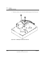
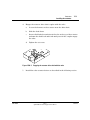
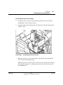
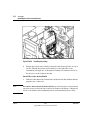
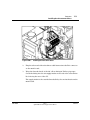
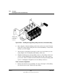
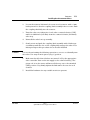
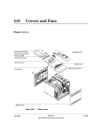
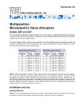
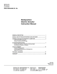
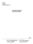
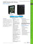
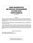
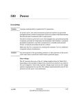
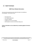
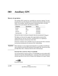
1130 Actuators
Installing the actuators
The actuators use pneumatic pressure (40 to 70 psi) to switch the valves
between their two positions.
1.
After installing the valves and valve box as described in the Valve Box
section, you can install the valve actuators.
2.
Set each actuator to the appropriate degree of rotation. Move the grenade
style pin to the hole on the actuator marked with the correct degree of
rotation, as shown below:
•
Four port valves—Place the pin in the 90° hole
•
Six port valves—Place the pin in the 60° hole
•
Ten port valves—Same as six port valves, but with the tubular 36°
actuator limiter on the pin.
60°
90°
Figure 1130-1
Jun 2001
Setting the actuator’s degree of rotation
Valves
Agilent 6890 Gas Chromatograph Service Manual
1 of 12
1130
Actuators
Installing the actuators
3.
Mount an actuator over each valve installed using two Torx T-20 screws.
Figure 1130-2
2 of 12
Mounting the actuator on the valve box
Valves
Agilent 6890 Gas Chromatograph Service Manual
Jun 2001
Actuators
Installing the actuators
4.
Engage the actuator drive shaft coupler with the valve.
a.
Loosen the hex nut on the actuator near the drive shaft.
b.
Slide the shaft down.
c.
Insert a flat bladed screw driver in the slot on the top of the actuator
and turn the shaft back and forth until you feel the coupler engage
the valve.
d.
Tighten the set screw.
Figure 1130-3
5.
Jun 2001
1130
Engaging the actuator drive shaft with the valve
Install the valve actuator drivers as described in the following section.
Valves
Agilent 6890 Gas Chromatograph Service Manual
3 of 12
1130
Actuators
Valve drivers
Valve drivers
The 6890 GC provides keyboard control for up to eight valve drivers which
are named Valve 1 through Valve 8.
Table 1130-1
6890 GC Valve Designations
Valve
Driver
Purpose
Valves 1–4
24 volt, 13 watt
Normal valve operation
Valves 5–6
24 volt, 100 mA
Relays/low power devices
Valves 7–8
48 Vdc or 48 Vac rms
Contact closures
There is a BCD input for controlling a multiposition valve. If a valve is
configured as a multiposition valve and the BCD is connected to this valve, a
position can be selected directly from the keyboard.
4 of 12
Valves
Agilent 6890 Gas Chromatograph Service Manual
Jun 2001
Actuators
Installing the valve actuator drivers
1130
Installing the valve actuator drivers
The valve actuators are driven by solenoid drivers which, when activated,
send high pressure air to the actuator to switch the valve.
Assemble the valve driver block
The valve driver block accommodates up to four valve drivers. A valve driver
must be installed for each valve/actuator installed.
Assemble the valve driver block as in Figure 1130-4. The example in this
procedure shows a valve driver block parts breakdown for a two valve system.
1.
Install two mounting posts on the intake/exhaust endplate (two large
threaded holes). Install an O-ring in the supply/exhaust ports on the
inside of the plate.
2.
Slide a valve driver over the mounting posts in the orientation shown.
Install two O-rings in the valve driver supply/exhaust ports as shown.
Mounting posts
Screw plugs
(may not be present)
O-ring
Figure 1130-4
Jun 2001
Assembling the valve driver block
Valves
Agilent 6890 Gas Chromatograph Service Manual
5 of 12
1130
6 of 12
Actuators
Installing the valve actuator drivers
3.
For each additional valve installed, install two more mounting posts and
a valve driver with O-rings in the same manner as the first.
4.
When all the drivers have been installed, screw on the other end plate
with the two hex screws as shown.
Valves
Agilent 6890 Gas Chromatograph Service Manual
Jun 2001
Actuators
Installing the valve actuator drivers
1130
Install the bracket and cabling
1.
Install the valve actuators as described earlier in this section before
installing the valve actuator drivers.
2.
Screw the valve driver bracket into the right side of the GC using the two
captive screws.
Figure 1130-5
3.
Assembling the valve driver block
Plug the connectors on the valve driver cable harness up through the
slots on the valve driver bracket.
Plug the larger 2 × 2 heater sensor connectors (P1, P2) into the outside
slots and the smaller 1 × 2 valve driver connectors (P3 to P6) into the
four middle slots.
Jun 2001
Valves
Agilent 6890 Gas Chromatograph Service Manual
7 of 12
1130
Actuators
Installing the valve actuator drivers
Figure 1130-6
4.
Installing the cabling
Plug in the heater/sensor lead(s) from the valve heater blocks on top of
the GC. Thread the heater/sensor lead(s) to the right side of the
instrument, through one of the keyhole wiring slots and into the P1 or
P2 detector on the actuator bracket.
Install the valve driver block
1.
Note
8 of 12
Slide the valve driver block down into the driver bracket until the drivers
plug into the connectors.
To remove drivers from the driver block, use a hex wrench to unscrew the
two hex screws on the left side of the block. Remove the driver, collapse the
block to the width of the remaining drivers and reinstall the hex screws.
Valves
Agilent 6890 Gas Chromatograph Service Manual
Jun 2001
Actuators
Installing the valve actuator drivers
Figure 1130-7
1130
Installing the valve driver block
2.
Plug the other end of the valve driver cable harness into the P22 connector
on the main board.
3.
Wrap the threaded ends of the 90° elbow fitting in Teflon® pipe tape.
Screw the fitting into the air supply intake on the side of the valve driver
block facing the rear of the GC.
The supply intake is the outside threaded hole, the one farthest from the
main board.
Jun 2001
Valves
Agilent 6890 Gas Chromatograph Service Manual
9 of 12
1130
Actuators
Installing the valve actuator drivers
Tubing from side
of actuators goes
to this row of
connectors
Figure 1130-8
Installing the supply fitting, tubing connectors, and actuator tubing
4.
Run a length of 1/4-inch tubing out the hole on the rear of the GC in the
lower left corner (when facing the rear of the instrument). Connect this
tubing to your air supply.
5.
Unscrew the screw plugs (if present) on the top of each driver you are
using. Replace the screw plugs with tubing connectors.
6.
Plumb the tubing from each installed actuator to the tubing connectors
on the corresponding driver. The tubing from the side of the actuator
goes to the connector farthest from the main board. Grip the tubing with
a piece of sandpaper and push it onto the tubing connector.
Valve actuator alignment
1.
10 of 12
Remove the valve box top assembly. See steps 1 through 3 of Installing
the valve box in section 1120 for the procedure.
Valves
Agilent 6890 Gas Chromatograph Service Manual
Jun 2001
Actuators
Installing the valve actuator drivers
Caution
Jun 2001
1130
2.
Loosen the actuator link arm lock screw at each actuator with a 3 mm
hex key wrench so that the coupling/shaft assembly is free to rotate. Push
the coupling shaft fully into the actuator.
3.
Turn the valve rotor index pin of each valve counterclockwise (CCW)
until it is 0.010-inch (0.25 mm) from the counterclockwise (left-hand)
valve stop.
4.
Reinstall the valve box top assembly.
5.
Gently rotate and push the coupling/shaft assembly with a blade-type
screwdriver until the slot on the coupling fully engages the valve rotor
index pin. Repeat this procedure for each valve installed.
Use care in performing the following operation so as not to accidentally turn
the valve rotor away from its preset (step 3) position.
6.
Make sure that all solenoid valves are turned “off” by the appropriate
valve controller. Turn on the air supply to the solenoid valve(s). The
piston rod of each actuator will move all the way out to the extended
(OFF) position. Very firmly tighten the link arm lock screw for each
actuator.
7.
Install the hardware for any variable restrictors present.
Valves
Agilent 6890 Gas Chromatograph Service Manual
11 of 12
1130
12 of 12
Actuators
Installing the valve actuator drivers
Valves
Agilent 6890 Gas Chromatograph Service Manual
Jun 2001