1
Technical Note 415
Valco Instruments Co. Inc.
Multiposition
Microelectric Valve Actuators
Models EMH and EMT
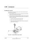
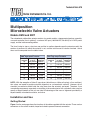
The microelectric multiposition actuator consists of a control module, a steppermotor/gearbox assembly,
a manual controller (use is optional), a universal AC input (100-240 VAC, 50-60 Hz) to 24 VDC power
supply, and the interconnecting cables.
The time it takes to step a valve from one position to another depends upon the actuator model, the
number of positions for which the actuator is set, and the total amount of rotation involved. Actual
times can be computed from the tables below.
EMH (high speed) actuator
EMT (high torque) actuator
Number of
Time req.
Time per
positions
to move
additional
set
one position position
Number of
Time req.
Time per
positions
to move
additional
set
one position position
NOTE: With the exception of Valco P type valves (which have a visible coil spring), all our multiposition valves are keyed to provide automatic alignment on a microelectric actuator. However, not all
standoffs (an extension which holds the valve away from the actuator) are keyed. Therefore, if you
are ordering components separately or retrofitting a valve and actuator with a standoff, make sure you
specify a keyed standoff so that you can take full advantage of the ease of alignment provided by a
keyed standoff, microelectric actuator, and valve.
Installation and Use
Getting Started
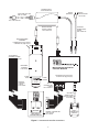
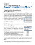
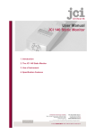
Figure 1 on the next page shows the functions of the cables supplied with the actuator. There are four
connectors on the control module, keyed and sized to prevent incorrect connection.
1
POWER SUPPLY
P/N PS24VDC-CE
BLACK
(GROUND)
LINE CORD (IEC-320)
P/N I-W-17600
BLACK/
WHITE STRIPE
+24-28 VDC
TO 110 OR 220 VAC
OPTIONAL
POWER INPUT
CABLE
P/N I-22535-CE
MOTOR DRIVER
OUTPUT CABLE
P/N I-22640-CE
MOTOR/GEARBOX
ASSEMBLY
P/N EMHMA-CE (High speed)
or EMTMA-CE (High torque)
TO EXTERNAL
CONTROL SYSTEM
PIN 1
MOUNTING
BRACKET
P/N I-22766
MULTIPOSITION ACTUATOR
CONTROL MODULE
CLAMP
RING
REMOTE
CONTROL
CABLE
P/N I-22696
P/N EMHCA-CE (High speed)
or EMTCA-CE (High torque)
CLAMP
SCREW
VALVE
MANUAL
CONTROLLER
CABLE
P/N I-22696-01
PIN 1
POSITION
PIN 1
STEP
PIN 1
OPTIONAL
SERIAL PORT
(RS-232) CABLE
P/N I-22697
HOME
ROTATION
PUSH BOTH BUTTONS
SIMULTANEOUSLY
TO REVERSE DIRECTION
MANUAL CONTROLLER
(Use optional)
P/N I-22679
Figure 1: Actuator and controller connections
2
DB-9
CONNECTOR
(FEMALE)
1.94"
1.00"
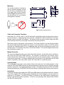
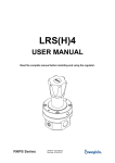
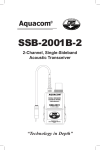
Mounting
4.44"
The actuator should be oriented so
that any potential leakage of liquid
from the valve or fittings flows away
from rather than into the actuator.
(below) Figure 2 provides the mounting dimensions for the stepper
motor/gearbox assembly.
.90"
2.19"
1.04"
2.3"
1.2"
1.375"
(CLAMPRING)
2.75"
1.00"
OK
.75"
OK
Figure 2: Mounting dimensions
Cable and Connector Functions
Input power (20 – 30 VDC, with 24 – 28 VDC preferred) is supplied through a miniature power connector: the inner pin is + voltage and the outer is ground. Average DC current requirement is 2.5 amps.
Standby current is less than 100 milliamps. The actuator should not share a power supply with other
noise-sensitive electronics, as the high current draw can cause problems.
Motor driver output is through the 10 pin connector. The 26-pin connector is for the manual controller
and remote digital input/output signals; the actuator can be controlled by either or both. The manual
controller has a pass-through port, so an additional cable can provide simultaneous control by an
external system. The three-pin connector is for RS-232 interface. The serial and digital functions are
fully described on pages 4 - 8.
Manual Controller
The manual controller allows the user to select the rotation direction, set the total number of positions,
and control the STEP and HOME functions. The controller is connected to the actuator control
module with the 26 pin ribbon cable. The manual controller has two functional modes – the operating
mode and the setup mode. The display indicates the current position in the operating mode, the total
number of positions in the setup mode, and an “EP” when there is a positioning error.
Operating Mode
This is the default mode; that is, the controller will be in this mode when it is initially powered. In this
mode the STEP and HOME functions are clearly labelled as the primary functions of the left and right
switches, respectively. To change the direction of rotation, momentarily depress the STEP and HOME
switches simultaneously. The DIRECTION LEDs will change, indicating that the direction has reversed.
Setup Mode
To shift into the setup mode, depress the STEP and HOME switches and hold them down for 8 seconds.
The position display LEDs will begin to flash, displaying the current setting for the total number of
positions in a full rotation. Use the STEP switch to increase or the HOME switch to decrease this
setting to the desired number of positions. To return to the operating mode, depress both switches
until the LEDs stop blinking.
3
Simultaneous Use of the Manual Controller and an External Control System
The manual controller has two identical connectors for input and/or output, permitting an external
system to be used simultaneously with the manual STEP and HOME commands. However, the
following precaution should be observed:
If the STEP and HOME functions are to be used by both systems, the external system control output
cannot be in the form of TTL signals; instead, the output must be a momentary signal asserted by a
contact closure or open collector driver. While TTL signals will cause no damage to either system,
they will effectively override the manual controller.
Connecting External Systems
An external control system can be connected to the actuator in several ways:
1. The Digital Input/Output connector is a 26 pin dual in-line connector which can mate to a mass
terminatable flat cable connector available from a number of manufacturers. The flat cable can
then be integrated into the control system.
2. The manual controller can be connected to the control module, and then a 26 pin dual in-line
connector and flat cable assembly can be attached to the manual controller. This allows dual
control as well as a visual indication of the actuator position.
3. A serial port can be connected from a host control system to the actuator, using the optional
RS-232 cable (Product No. I-22697).
Digital Protocols
Hardware Input / Output Protocols
Digital input/output control of the multiposition actuator is designed for simplicity and flexibility of
function. The simplest control of the actuator can be accomplished with two output control lines –
STEP and HOME. The chart on the next page lists other control options.
The inputs are held to a logical high (+5 volts) by pull-up resistors, and are designed to be driven low
either by contact closure, 5 volt digital logic, or open collector transistor outputs. The signal polarity is
defined as “negative true” – asserting the signal involves shorting the signal (in the case of contact
closure) or driving it (in the case of logic or transistor signals) to within 0.8 volts of ground potential.
These input signals must be at least 30 milliseconds in duration. The outputs are also “negative true”
signals driven by standard high speed CMOS gates, capable of driving standard logic input gates.
They include the BCD position, motor run, rotational direction, and error signals. If the actuator stops
out of position due to a stuck valve, the BCD output is set to “0” (all lines high for a negative true
output).
The digital interface is made through a 26 pin connector which also provides power (+5 volts/100 ma
maximum) and ground outputs. The ground should be connected to the control system to maintain
commonality between the actuator and the controlling device. If you intend to provide your own power
supply, make sure that it has an isolated output or that it shares a common ground with the controlling
system.
Software Input Protocols
(chart on next page, discussion on page 6)
4
Pin
Color
Signal
1
brown
Home
2
red
Motor run
3
orange
4
5
Direction
Pin
Color
Signal
Direction
Input
14
yellow
4 BCD
Output
Output
15
green
20 BCD
Output
Step
Input
16
blue
2 BCD
Output
yellow
Error
Output
17
violet
10 BCD
Output
green
Manual Dir.
Input
18
gray
1 BCD
Output
6
blue
Direction
Output
19
white
80 BCD
Input
7
violet
Auto Dir.
Input
20
black
8 BCD
Input
8
gray
Data latch
Input
21
brown
40 BCD
Input
9
white
+5 VDC 100 ma
Output
22
red
4 BCD
Input
10
black
Ground
Output
23
orange
20 BCD
Input
11
brown
80 BCD
Output
24
yellow
2 BCD
Input
12
red
8 BCD
Output
25
green
10 BCD
Input
13
orange
40 BCD
Output
26
blue
1 BCD
Input
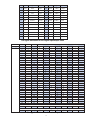
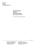
Pin signal definitions for the Digital Input/Output cable
Mode:
Input type:
Position:
Data Input Lines
8 BCD 10 BCD 20 BCD 40 BCD 80 BCD
–
–
–
–
–
–
–
–
–
–
–
–
–
–
–
–
–
–
–
–
–
–
–
–
–
–
–
–
–
–
–
–
–
–
–
–
–
X
–
–
–
–
X
–
–
–
–
X
–
–
–
–
X
–
–
–
–
X
–
–
–
–
X
–
–
–
–
X
–
–
–
–
X
–
–
–
X
–
–
–
–
X
–
–
–
–
X
–
–
–
–
X
–
–
–
–
X
–
–
–
–
X
–
–
–
–
X
–
–
–
–
X
–
–
–
–
X
X
–
–
–
X
X
–
–
–
X
X
–
–
–
X
X
–
–
–
X
X
–
–
–
X
X
–
–
–
X
X
–
–
–
X
X
–
–
X
–
–
–
–
SD0
BCD
1
2
3
4
5
6
7
8
9
*
*
*
*
*
*
10
11
12
13
14
15
16
17
18
19
*
*
*
*
*
*
20
SD2
Parallel
1
2
*
3
*
*
*
4
*
*
*
*
*
*
*
5
*
*
*
*
*
*
*
*
*
*
*
*
*
*
*
6
SD3
Binary
1
2
3
4
5
6
7
8
9
10
11
12
13
14
15
16
17
18
19
20
21
22
23
24
25
26
27
28
29
30
31
32
1 BCD
X
–
X
–
X
–
X
–
X
–
X
–
X
–
X
–
X
–
X
–
X
–
X
–
X
–
X
–
X
–
X
–
40
7
64
–
Code sequence break
–
–
–
–
–
X
–
–
Code sequence break
–
–
–
–
–
–
X
80
8
128
2 BCD
–
X
X
–
–
X
X
–
–
X
X
–
–
X
X
–
–
X
X
–
–
X
X
–
–
X
X
–
–
X
X
–
4 BCD
–
–
–
X
X
X
X
–
–
–
–
X
X
X
X
–
–
–
–
X
X
X
X
–
–
–
–
X
X
X
X
–
Pin signal definitions for the various input modes
5
Software Input Protocols
The input modes are selected by the serial port command “SDn”, with n = 0, 1, 2, or 3. Mode
information is stored in non-volatile memory and maintained during power up/down sequences. The
modes are:
SD0 (default) Binary Coded Decimal (BCD) input mode. For the 96 possible input positions, all
8 digital input data lines are required. Refer to the chart on the previous page for the signal line
definitions.
SD1 Disables the digital inputs to prevent user intervention during automated control via the serial
port. It resets to SD0 during the power up sequence.
SD2 Redefines the data input lines so that each input line equates to only one actuator position;
any and all combinations of data input lines are invalid. This mode can support only 8 positions:
1 BCD = position 1; 2 BCD = position 2; 4 BCD = position 3; 8 BCD = position 4; 10 BCD=
position 5; 20 BCD = position 6; 40 BCD = position 7; and 80 BCD = position 8. The offset value
SO is set to 1, and since the number of positions is limited to 8, any user-set NP value greater
than 8 will revert to 8. (See the chart on the next page for more explanation of NP and SO.)
SD3 Redefines the data input lines to a binary input instead of BCD. This reduces the number of
input lines required to select positions above 9. For example, BCD mode inputs for any position
between 10 and 15 requires the use of data input lines 1, 2, 4, 8, and 10 BCD. In the binary
mode, only lines 1, 2, 4, and 8 BCD are required. The position values for the binary mode are
calculated the same way as those for the BCD mode, except that all combinations of the input
lines are valid numerical positions.
Serial Control of the Actuator
Establishing Serial Communications
Items required:
• Valco cable assembly I-22697 or equivalent
• Terminal emulation or communication software such as QModem, ProComm Plus™,
or HyperTerminal® (included with Windows®), running on a PC-compatible computer
1. Connect the I-22697 cable to the actuator as indicated in Figure 1, and set the serial port at 9600
baud, no parity, 8 data bits, 1 stop bit, no hardware or software handshaking.
2. With the software running, check the bi-directional communication link between the keyboard/
monitor of the computer and the serial port by typing VR<enter>. If the link is functioning and an
actuator ID has not been set, a message similar to the following will appear on your monitor, giving
the program number and date of the actuator firmware.
I-PD-ETX88RXX (XX = revision number)
2 - Aug - 99
If there is no response, it is possible that the ID has already been set. To force a response from
a device with an unknown ID, type *VR<enter>. The asterisk is a substitute ID wild card which will
elicit a response from all devices on line, no matter what their ID is.
Programmer’s note: In order for multiple RS-232 slave devices to be controlled from one serial port,
they must all keep their outputs deactivated until they need to respond. When a device responds, it
asserts its output low for 2 milliseconds before sending the first character to clear the host UART’s
input. Nevertheless, it is possible that the UART will sense a framing error or receive a bogus
character. The programmer should be prepared to handle this possibility in software.
ProComm Plus™ is a registered trademark of Symantec Corporation
HyperTerminal® is a registered trademark of Hilgraeve, Inc.
Windows® is a registered trademark of Microsoft Crop.
6
Serial Commands
NP<enter>
Displays the number of positions the actuator is currently set to index
NPnn<enter>
Sets the number of positions (nn) for the current valve
CWnn<enter>
Sends the actuator clockwise to position nn (from 1 to NP)
CCnn<enter>
Sends the actuator counterclockwise to position nn (from 1 to NP)
GOnn<enter>
Sends the actuator to position nn (from 1 to NP) via the shortest route
CP<enter>
Displays the current position
SD<enter>
Displays the digital input status where 0 = enabled and 1 = disabled
SDn<enter>
Sets the digital input status to [0] BCD, [1] disabled, [2] parallel, or
[3] binary. NOTE: Setting the status to [1] locks out communication
through the manual controller and remote control cables, so digital input
status defaults to [0] at power up.
SM<enter>
Displays the current default rotational direction for the digital inputs.
SMl<enter>
Sets the default rotational direction for the digital inputs to [F] for forward
rotation, [R] for reverse rotation, or [A] to automatically choose the
shortest route. This feature can be used instead of external wiring tied
to the Manual and/or Autodirection input lines on the Digital I/O port.
ID<enter>
Displays the current device ID setting
IDn<enter>
Sets the device ID to value n, from 0 to 9
NOTE: When the ID feature is enabled, all commands to the device
must be prefaced by the ID. Entering ID* clears the ID.
SB<enter>
Displays the current baud rate
SBnnnn<enter>
Sets the baud rate to 1200, 2400, 4800, 9600 (default), 14400,
19200, 28800, or 38400. The parity setting, number of data bits,
and number of stop bits cannot be changed. (See section entitled
Setting a New Baud Rate on the next page)
SL<enter>
Displays current Data Latch signal status
SLn<enter>
This command displays or changes the requirement for a Data Latch
signal to accompany BCD inputs. When set to [0] (factory default), the
data latch is required for BCD inputs. When set to [1], the data latch is
NOT required. This feature can reduce the number of control lines
required for a system with a dedicated BCD output port and only one
actuator connected. NOTE: Be sure all the BCD inputs are asserted
within 20 milliseconds of each other or the actuator may be misdirected.
SO<enter>
Displays the current offset value
SOnn<enter>
Sets the offset value of the first position to be any number from 1 to
96 minus the total number of positions. Example: for a 10 position
valve, the offset can be set from 1 to 86. (See section entitled Using
the Offset Feature beginning on the next page.)
VR<enter>
Displays the part number and date of the firmware
/?<enter>
Displays a list of valid commands
Note: In this chart, nn represents numbers to be entered and l represents letters.
7
Serial Communication Protocol
Serial communication is based on an ASCII string protocol. Carriage
return (OD hex) characters parse the communications by defining the
end of each command. Line feed characters (OA hex) are ignored.
A three-pin connector is used for the RS-232 interface: pin assignments are indicated at right. Software flow control (Xon/Xoff) and hardware handshaking are not supported.
Serial Port (RS-232) Cable
Pin # Signal Description
1
Ground
2
Transmit to host
3
Receive from host
With the software-settable device “ID” feature enabled, the serial port output (transmit line) of the
actuator is disabled (high impedance). Thus, as many as ten actuators can be controlled from a single
host serial port for a temporary multidrop application. For permanent multidrop applications, the
RS-485 option is the factory-recomended solution. The table on the previous page describes and
explains all the commands available.
Using the Device ID Feature
Actuators are shipped from the factory with this feature disabled. When it’s enabled, the actuator
responds only to commands which begin with the correct ID prefix, allowing up to 10 actuators to be
controlled from one serial port. A single command can be broadcast to all actuators by using an
asterisk (*) as the command prefix. Note: Any broadcast command which elicits a response from the
serial port (such as *VR or *ID1) will receive a combined and unintelligible response.
To set the ID of an actuator, connect it to an RS-232 serial port as shown in Figure 1 on page 2.
Caution: When installing or replacing actuators on a shared serial port, make sure that no two
devices have been set to the same ID number.
1. Remove all of the actuators from the serial daisy chain except the one for which you are setting the ID.
2. Type VR <enter>. You should get a response giving the firmware version, indicating that serial
communication with the actuator is established. If there is no response, type *VR<enter> to see
if the ID is already set. If there is still no response, check the cabling and connections.
3. To set an ID, type IDn<enter>, where n is the new ID, from 0 to 9.
To change an ID, type i IDn<enter>, where i is the current ID and n is the new ID.
To disable the ID feature, type i ID*<enter>, where i is the current ID.
Setting a New Baud Rate
To permanently set a new baud rate for the actuator:
1. Establish communications with the actuator at the current baud rate.
2. Issue the command SBnnnn to temporarily change the baud rate to the desired rate. If the power
goes down at this point, the baud rate will revert to the last permanent setting.
3. Change the host computer to the same baud rate just set in the actuator, and verify that you can
establish communications.
4. Re-issue the same SBnnnn command you did previously (in Step 2), and the current baud will be
made permanent.
Using the Offset Feature
This feature makes it possible to control more than one actuator without increasing the number of
BCD input lines. The actuator’s SO value can be set from “1” to “96”, minus the current NP value (the
number of positions the actuator is set to index). Once an SO value is set, that value is the first (or
lowest) position an actuator will recognize. The factory SO setting is “1”, so an actuator with an NP
value of 10 responds to move commands for positions “1” to “10”. If the SO value is changed to “10”,
8
the actuator will respond only to move commands for positions “10” through “19”. For any setting of
SO and NP, the lowest valid position will be the SO value and the highest valid position will be the SO
value plus the NP value minus 1; i.e., the actuator will respond to commands for position SO through
position {SO + NP - 1}.
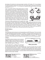
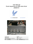
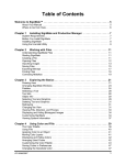
OUTLET
Here is an example of how this can be used to set up a 31-stream
stream selection system using six dedicated BCD lines and two
16-position valves and actuators. First, use the serial port command “SL1” to enable the auto-latching feature on both actuators.
(This eliminates the need for a data latch signal.) Configure the
second actuator using the serial port command “SO16”, giving it a
valid position range of 16 to 31. Use a piece of tubing to connect
port 16 of the first valve (on the actuator with the SO value still at
the factory setting of “1”) to the common port of the valve on the
second actuator (which now has the SO set to “16”). Connect
streams 1 through 15 to ports 1 through 15 on the first valve, and
streams 16 through 31 to ports 1 through 15 on the second valve.
S1
S16
S15
S4
S31
S19
VALVE 1
VALVE 2
CONTROL MODULE
FOR ACTUATOR 1
CONTROL MODULE
FOR ACTUATOR 2
PARALLEL CONTROL LINES
Figure 3: Use of the offset feature
This system will step sequentially from 1 through 31 with a single
BCD instruction. However, when positions are selected in a random sequence, position 16 must always
be requested before any positions higher 16 are selected. Figure 3 helps illustrate this: since both
actuators respond to a command to go to position 16, stream 16 will flow through valve 1/port 1, out
the common port of valve 2, into valve 1/port 16, and out of the common port of valve 1. Thereafter,
any stream select command that is above 16 will move only valve 2; when a move command for a
position less than 16 is given, valve 1 will move and cut off all flow from valve 2.
RS-485 Option
Software
The RS-485 option involves three minor software adaptations to the RS-232 protocol. The first is that the
ID range is extended to include the characters “A” through “Z”, with upper and lower cases treated as the
same ID. The second change is that the ID is required (either numbers from 0 to 9 or letters from A to
Z), and must be included in all commands. The factory-set default ID for all devices is “Z”. The third
adaptation is that all commands must include a forward slash [/] as the start-of-message character.
Hardware
The RS-485 hardware includes two 3-pin connectors
(Figure 4) used as in/out connectors for easy daisychaining of additional devices. Wired in parallel, the
signal assignments are as follows: Pin 1 is Ground,
Pin 2 is Phase B, and Pin 3 is Phase A.
JUMPERS 1 AND 2
Figure 4: Control module,
The four male pins in a vertical row to the left of
showing jumper locations
these connectors are jumper headers, used to add or
remove terminating resistors from the communication lines. The top two and the bottom two should
be jumpered when termination is required. The RS-485 hardware specifications require termination at each end of the communication line, so in a daisy-chaining application the jumpers should be
removed from all the intermediate devices. The RS-485 port on the host computer or controlling device
generally includes terminating resistors, so only the actuator at the far end of the communication string
needs to have the jumpers installed.
TN-415 10/14