1
SECTION V
TOWN OF WEST SILOAM SPRINGS
WATER AND SEWER CONSTRUCTION SPECIFICATIONS
DIVISION I
GENERAL SPECIFICATIONS
PART 101 - SCOPE AND LOCATION
101.1
The location of the project is in the Town of West Siloam, Oklahoma hereinafter
referred to as City. The character and exact location of the project are shown on the
Drawings
101.2
The site and/or rights-of-way upon which the work is to be performed is shown on
the Drawings. The Contractor agrees that the site and/or rights-of-way provided
is adequate for the performance of the work. If any additional working area is
required, the Contractor shall, at his expense, make arrangements for such
working area.
PART 102 - SCOPE, NATURE, AND INTENT OF SPECIFICATIONS AND DRAWINGS
102.1
The Specifications and Drawings are intended to supplement, but not necessarily
duplicate each other; and together constitute one complete set of Specifications
and Drawings, so that any work exhibited in the one and not in the other shall be
executed just as if it had been set forth in both, in order that the work shall be
completed according to the complete design or designs as decided and
determined by the Engineer.
102.2
The Drawings are not intended to be scaled for dimensions, and if dimensions
not shown on the Drawings are required, the Contractor shall request them from
the Engineer. Where existing utility lines or other sub-surface obstructions are
shown on the Drawings, the same have been located as nearly as practicable
from information furnished by owners of such, and from such surface indications
as may exist at the work site. Such obstructions are shown for the purpose of
advising the Contractor that they may interfere with the work to be done
hereunder, but not for the purpose of indicating that the work can be performed
without such interference.
102.3
Where soundings are shown on the drawings, the depths are determined by
driving a drill rod, using the churn method with water lubrication, to a maximum
depth of nine feet or to refusal, whichever is lesser in depth. By showing
soundings on the drawings, the City represents only that material of hardness
and character which could be penetrated by a drill rod found above the depth of
sounding as shown at the point where the drill rod was driven.
102.4
Where exploratory drilling is indicated to have been performed on the plans,
boring logs will be available for review at the office of the Engineer. The logs will
be furnished for information purposes only, and are not to be construed as a true
representation of actual subsurface conditions.
Page 1 of 9
Division I - General Specifications
May 2005
102.5
Should anything be omitted from the Specifications and Drawings which is
necessary to a clear understanding of the work, or should it appear various
instructions are in conflict, the Contractor shall request written instructions from
the Engineer before proceeding with the construction affected by such omissions
or discrepancies.
102.6
The Contractor's responsibility for construction covered by conflicting
requirements, not provided for by addendums prior to the time of opening bids for
the work represented thereby, shall not extend beyond the construction in
conformity with the cheaper of the said conflicting requirements. Any increase in
cost of work requested to be done in excess of the cheaper of the conflicting
requirements will be paid for as Extra Work as provided for herein.
PART 103 - LINES AND GRADES
103.1
All work done under this Contract shall be done to the lines, grades, and
elevations shown on the Drawings. All lines and grades shall be completed by
Licensed Surveyor paid for by the contractor. The Contractor shall provide all
batterboards, straight edges, and other materials for lines, levels, and measurements;
and shall set all batterboards under direction of the Engineer. The Contractor shall give
the Engineer at least forty-eight (48) hours notice as to the location where stakes are
required.
PART 104 - SATURDAY, SUNDAY, HOLIDAY AND NIGHT WORK
104.1
No work shall be done between the hours of 6:00 p.m. and 8:00 a.m., nor on
Saturday, Sunday, or legal holidays without the written approval or permission of
the Engineer in each case, except such work as may be necessary for the proper
care, maintenance, and protection of work already done, or of equipment, or in
the case of an emergency.
PART 105 - PROTECTION OF PROPERTY
105.1
The protection of City, State and Government monuments, street signs, and
other City property is of prime importance, and if the same be damaged,
destroyed or removed, they shall be repaired, replaced or paid for by the
Contractor. Disturbance to this property must first be approved by the agency
that controls it.
105.2
No valve or other control on any utility main or building service line shall be
operated for any purpose by the Contractor.
105.3
At places where the Contractor's operations are adjacent to, or crossing, the path
of railway, telegraph, telephone, cable, electric, and gas lines, or water lines,
sanitary sewers, and storm sewers, damage to which might result in expense,
loss or inconvenience, work shall not be commenced until all arrangements
necessary for the protection thereof have been made. Contractor shall notify the
Notification Center of Oklahoma One-Call System, Inc. of any excavation or
Page 2 of 9
Division I - General Specifications
May 2005
demolition prior to the commencement of such work. Notification shall be made
no sooner than ten (10) days, nor later than forty-eight (48) hours prior to start of
work, excluding Saturdays, Sundays, and legal holidays.
105.4
The Engineer has attempted to locate all storm sewers, culverts, buried telephone
or electrical conduits, sanitary sewers, water mains, and gas mains that might
interfere with the construction of this project. The Contractor shall cooperate with
the owners of any underground or overhead utility lines in their removal and
rearrangement operations in order that these operations may progress in a
reasonable manner and duplication or rearrangement work may be reduced to a
minimum, and that services rendered by those parties will not be unnecessarily
interrupted. The revision and crossings of the various types of lines shall be
made as follows:
a) Storm sewers and culverts may be removed at the time of crossing or may be
adequately braced and held in position while the pipe is placed beneath them. If
the storm sewer or culvert is removed, it shall be replaced with pipe of the same
type and size as that removed, and it shall be re-joined to the undisturbed line
with a joint satisfactory to the Engineer. Backfill over the main, up to and around
the storm sewer, shall be thoroughly compacted in order that no settlement will
occur. The revision and crossing shown on the Drawing shall be at the expense
of the Contractor. In the event lines, other than those shown on the Drawings,
are encountered and fall within the standard trench limit and, in the opinion of the
Engineer, revision of the line is necessary for the construction of the project, the
Contractor will be reimbursed for the extra cost of the crossing or revision under
the "Extra Work" clause of the Contract.
b) All overhead and buried telephone cable and electrical conduits, and gas mains
to be revised or crossed by the construction of this project shall be protected in
accordance with the directions of the utility company owning the conduits and/or
mains. The Contractor shall notify the companies and obtain their permission
before making any crossing or revisions. The revision and crossing shown on
the Drawing shall be at the expense of the Contractor. In the event lines other
than those shown on the Drawing are encountered and fall within the standard
trench limit and, in the opinion of the Engineer, revision of the line is necessary
for the construction of the project, the Contractor will be reimbursed for the extra
cost of the crossings or revision under the "Extra Work" clause of the Contract.
Any overhead cables or buried cables or conduits or gas mains damaged by the
Contractor shall be repaired at his expense to the satisfaction of the Engineer
and of the owner.
c) The Contractor shall not remove any water or sanitary sewer lines except as
directed by the Engineer or as required by the Drawings and Specifications, and
shall adequately brace and protect them from any damage during construction.
Any existing water main or sewer main or lateral damaged by the Contractor's
operation will be repaired by the City's maintenance forces. The Contractor shall
notify the City immediately after damaging any pipe. The repairs will be made at
the Contractor's expense. ·
Page 3 of 9
Division I- General Specifications
May 2005
105.5
105.6
The location of utility service lines serving individual properties mayor may not
be shown on the Drawings, but the Contractor shall assume that such service
lines exist whether or not they are shown on the Drawings, and it shall be the
responsibility of the Contractor to make any necessary changes in the line and/or
grade of such services, or to secure the necessary changes therein to be made
by the particular utility company involved or other owner thereof, or by an agent
or individual contractor approved by such utility company or other owner.
Contractor shall pay the cost of all such revisions whether performed by
contractor, the utility company, or other owner, or an approved contractor. In the
event of interruption of a utility service as a result of accidental breakage,
Contractor shall promptly notify the Engineer and the owner of the utility, and
shall repair or cause the same to be repaired, in the same manner as necessary'
changes above provided for, and the Contractor shall do all things necessary to
see to the restoration of services as promptly as may be reasonably done. All
sanitary sewer service lines damaged shall be replaced with cast iron pipe,
regardless of type or kind damaged.
In the event the Contractor in any way fails to comply with the requirements of
protecting, repairing, and restoring of any utility or utility service, the Engineer
may, upon forty-eight (48) hours' written notice, proceed to protect, repair, rebuild
or otherwise restore such utility or utility service as may be deemed necessary,
and the cost thereof will be deducted from any money due or which may become
due the Contractor pursuant to the terms of his contract.
PART 106 - CONNECTIONS
106.1
All connections to existing water mains shall be made by the Contractor, unless
noted otherwise. The Contractor shall perform his work so that these
connections may be readily made. All transfer of building service line
connections from the existing to the new main shall be made by the Contractor
after the main has been backfilled, tested, and chlorinated, but before any
sidewalks, driveways, curbs, and/or paved roadways, are replaced.
106.2
The Contractor shall not make any unauthorized connections to a sewer, nor
shall he permit any such connections to be made. If the Contractor is properly
authorized by the Engineer to make connections by installing tees in the sewer
under construction, such installation shall conform to the regulation of the City.
PART 107 - REFERENCES TO OTHER SPECIFICATIONS
107.1
Page 4 of 9
Where a standard such as American Society for Testing Materials, American
Concrete Institute, American Standards Association, American Water Works
Association, or other agency designation is specified for a material, that
designation shall be the current revision, either tentative or adopted. If a
referenced specification is in conflict with these specifications, the
specifications shall govern.
Division I- General Specifications
May 2005
PART 108 - PROTECTION OF MATERIALS
108.1
All materials delivered to the site of the work shall be adequately housed and
protected against deterioration according to the standard accepted procedures.
The Contractor shall keep his storage yards in good order, pile his materials
neatly, and protect them from damage.
PART 109 - TESTING
109.1
Materials: All materials required to be tested shall be tested by a laboratory approved by
CNE. No material shall be accepted for construction unless it bears the approval of the
laboratory. Reports of tests shall be forwarded to the Engineer and City. Before final
acceptance of the project, all materials shall be tested and shall be found in good and
proper condition, or shall be placed in such condition.
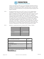
109.2
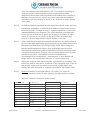
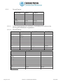
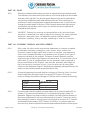
Testing of Manholes: All manholes will be tested using the vacuum test method,
following the manufacturer's recommendations for proper and safe procedures.
The vacuum tester shall be as manufactured by Cherne Industries or equal.
All pipes for vacuum testing entering the manhole shall be installed at the top
access point of the manhole.
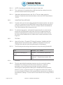
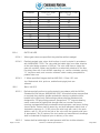
A vacuum of 10 inches of mercury (Hg)(5.0 psi) shall be drawn on the manhole
and the time shall be measured for the vacuum to drop to 9 inches of mercury
(Hg)(4.5 psi). The manhole shall pass the test if the time measurement exceeds
the values indicated in the following table:
Vacuum Test Timetable
Manhole Diameter - Inches
Depth-feet
4
8
12
16
20
24
+Each 2'
48 Inches
10 sec.
20 sec.
30 sec.
40 sec.
50 sec.
60 sec.
+5 sec.
60 Inches
13 sec.
26 sec.
39 sec.
52 sec.
65 sec.
78 sec.
+6.5 sec.
72 1nches
16 sec.
32 sec.
48 sec.
64 sec.
80 sec.
96 sec.
+8.0 sec.
96 1nches
19 sec.
38 sec.
57 sec.
76 sec.
95 sec.
114 sec.
+9.5 sec.
144 1nches
21 sec.
44 sec.
65 sec.
88 sec.
110 sec.
132 sec.
+11 sec.
Manhole depth shall be rounded to the nearest foot. Intermediate values shall be
interpolated. For depths abover 24 feet, add the values listed on the last line of
the table for each 2 feet of additional depth.
If the manhole fails the vacuum test, the contractor shall perform additional
repairs and repeat the test procedures until satisfactory results are obtained.
Page 5 of 9
Division I - General Specifications
May 2005
All repairs and testing are the responsibility of the Contractor and will be
performed at no additional cost to the City.
No payment will be made for any manholes which have not passed the vacuum
test.
109.3
Testing and Chlorinating Water Mains: Testing and chlorinating water mains will
be performed by the Contractor. Water mains shall be testing in accordance with the
Standard Specifications for "Installation of Ductile Iron Water Mains and Their
Appurtenances," AWWA Designation C-600. The pressure test of 150 psi shall
be for thirty minutes' duration . If the line passes the test without significant
pressure drop, a leakage test shall be made at the normal operating pressures
under which the line is to operate for two hours' duration. Before being placed in
service, all mains shall be chlorinated in accordance with "AWWA Standard for
Disinfecting Water Mains," AWWA Designation C-651. Where temporary plugs'
are required for pressure testing, the contractor shall furnish and install the plug
and temporary blocking, and remove after testing is complete. The cost shall be
included in the unit price bid for pipe. No additional payment will be made.
PART 110 - "OR APPROVED EQUAL" CLAUSE
110.1
When a material is specified or shown on the Drawings by brand or
manufacturer's name, any other material that will adequately perform the same
function, in the opinion of the City, may be accepted for use.
PART 111 - DeWATERING
111.1
The Contractor shall provide all necessary pumps, drains, dams, well points, and
other means for removing water from, or preventing water from entering the
trench or other excavation until the project is completed. Sufficient pumps or
other works shall be made available at all times to hold the water at a safe level
as determined by the Engineer. Water from the excavation shall be properly
disposed of so that no damage or interference results to public health, public or·
private property, completed or uncompleted work, other projects, or streets.
PART 112 - SAFETY
112.1
Excavations: The Contractor shall adequately shore, or sheet, and brace the
excavation, or shall slope the sides of the trench in accordance with the State of
Oklahoma Department of Labor requirements.
112.2
Explosives: In handling explosives used during the construction of the project,
the Contractor shall adhere to all Federal and State Laws and City Ordinances
regulating the purchase, transportation, storage, handling, and use of such
explosives. All blasting shall be done in strict.accordance with City Ordinance
Page 6 of 9
Division I - General Specifications
May 2005
#19947. No blasting shall be done without obtaining a "Blasting Permit" from the
City and presence of the Inspector. All equipment, tools, and materials used
shall be of the correct type and in good conditions for the operation. The
Contractor shall take all necessary precautions to avoid damage to property
resulting from the transportation, storage, handling and use of explosives.
Before blasting, the Contractor shall cover the area to be blasted with steel mesh
mat or other suitable material, reinforced with timbers of sufficient weight so that
rock and debris will be confined to the excavation. Any blasting within ten feet of
a water, sewer, gas, or pipe line shall be done with very light charges, and ·
utmost care should be taken to avoid disturbance to these lines. All locations for
blasting shall be subject to approval of the Engineer.
112.3
Danger Signals and Protection: When the Contractor is performing any type of
construction or excavation work, or is stockpiling or storing any materials or
equipment upon or adjacent to any street, alley, sidewalk, residence, public
ground, or other location that is likely to be subject to pedestrian or vehicular
traffic, he shall furnish, erect, and maintain substantial guard rails, safety fencing,
lights, and traffic control devices around the project to protect pedestrians,
animals, and vehicles from injury or damage. All traffic control shall be in
accordance with the Manual of Uniform Traffic Control Devices and
Procedures for Street Use and Temporary Traffic Control. Safety and traffic
control devices shall be installed and removed only at the direction of the
Engineer. The Contractor shall provide sufficient proper signals and flagmen for
warning during construction, excavation, and blasting operations.
112.4
Power Lines: No person, materials, or equipment shall come within six feet of
any power line carrying more than 440 volts unless the electric power services
has been first discontinued.
112.5
Fire Prevention and Protection: The Contractor shall take all necessary
measures to prevent fire, and shall provide satisfactory fire fighting means at the
location of work.
112.6
Interference with Traffic: The Contractor shall construct and maintain adequate
and safe bridges or crosswalks over excavations, where required. When a
roadway or sidewalk is not closed, the Contractor shall provide a safe substitute
route for any portion obstructed by his operations. If a roadway or sidewalk is
closed to traffic, the Contractor shall provide and mark detours. As directed by
the Engineer, construction across roadways or sidewalks may be done by open
excavation.
Condition of Equipment and Materials: All equipment, tools, appliances, and
112.7
Page 7 of 9
materials used in connection with the project shall be handled and operated only
when they are in safe operating condition and in accordance with a standard
safety procedure.
Division I - General Specifications
May 2005
PART 113 - REMOVAL OF CONDEMNED MATERIALS AND STRUCTURES
113.1
The Contractor shall remove from the site of the work, without delay, all rejected
and condemned materials or structures of any kind brought to or incorporated in
the work . Upon his failure to do so, or to make satisfactory progress in so doing,
within forty-eight (48) hours after the service of a written notice from the Engineer
ordering such removal, the condemned material or structure may be removed by
the City and the cost of such removal will be taken out of the money that may be
due or may become due the Contractor. No such rejected or condemned
material shall again be offered for use by the Contractor.
PART 114 - CLEAN-UP
114.1
Immediately upon installation of any portion of the work, the Contractor shall
restore all fills, topsoil, and utilities to their location and condition prior to
construction.
114.2
Immediately upon installation of any block in length of the work herein
contemplated, the Contractor shall remove all materials, tools, debris, excess
excavated material, and equipment; and restore the site in a manner satisfactory
to the Engineer.
114.3
Clean-up and restoration of service line transfers shall be made immediately
following each transfer installation.
PART 115 - PLACING WORK IN SERVICE
115.1
If desired by the City, portions of the work may be placed in service when
completed and the Contractor shall give prior access to the work for this purpose,
but such use and operation shall not constitute an acceptance of the work .
PART 116 - SUBMITTALS
116.1
The Contractor shall submit to the Engineer, six (6) copies of material submittals
for all material he proposes to use. Construction shall not begin until the
Engineer has approved the submittals in writing.
116.2
Submittals for pipe shall consist of notarized certifications, from the
manufacturer, that the pipe was manufactured and tested in accordance with the
applicable specifications. The certifications shall indicate the pipe diameter, the
pressure rating, and the batch number from which the pipe was manufactured.
For concrete and steel pipelines 16-inches and larger, a detailed laying schedule
prepared by the manufacturer shall be submitted, along with the detaildesign
calculations.
116.3
Submittals for material other than pipe shall consist of manufacturer's product
literature or shop drawings, indicating dimensions and material specifications.
Page 8 of 9
Division I - General Specifications
May 2005
Submittals shall include reference to compliance with AWWA, ASTM, NSF, and
other applicable standards.
116.4 All delivery tickets, including factory certification of ductile iron pipe, shall be
surrendered to City Inspector Henry Ward.
SECTION ENO
Page 9 of 9
Division I - General Specifications
May 2005
DIVISION II
MATERIAL SPECIFICATIONS
APPROVED FITTINGS MANUFACTURERS
Tapping Saddles and Valves
Mueller (DIP)
Clow (DIP)
American (DIP)
Tyler (DIP)
PowerSeal (DIP)
Smith-Blair (DIP)
Hanson Concrete (Cone)
Price 8ros(Conc)
TD Williamson(Conc)
Baker Series 428 (Steel)
Rockwell 622 (Steel)
Dresser (DIP)
Couplings for Out-of-Round Cl Pipe
Viking-Johnson
Smith-Blair
Straub
Check Valves
M&H
American Flow Control
Mueller
US Pipe
Clow
Kennedy
Watts
Restrained Joint Systems
American Flex Ring (DIP)
EBAA Megalug (DIP,PVC)
Ford Meter Box Uni-Flange(DIP,PVC)
Star StarGrip (DIP,PVC)
Price Snap Ring & Harness Joint (Cone)
Hanson Snap Ring & Harness Joint (Cone)
Northwest weld (Steel)
Hanson weld (Steel)
USPipe TR Flex (DIP gravity sanitary only)
Griffin SNAP-LOK (DIPgravity sanitary only)
McWane THURSTLOCK (DIPgravity
sanitary only)
4-Way Fire Hydrants
American Darling
Mueller (Aquagrip allowed)
Resilient Wedged Gate Valves
American
Mueller (Aquagrip allowed)
M&H
Clow
Kennedy
US Pipe
AVK
Ball Valves
3-Way Hydrants
American Darling B84B
Kennedy Guardian
Mueller Centurian (Aquagrip allo wed)
1
Valve Boxes
(Includes Debris C,p)
Tyler 6850 Series 562-S
I
1
East Jordan 85502737 (562-S)
SIGMA VB 262-35
Star VB 562SHD
4" Reversible Rim & 23 %" Lids (Water)
Neenah 1797-4R-TUL-WAT
Deeter 1155-TUL-WAT
East Jordan 2132R-TUL-WAT
Sigma MH121WV-35
Uniflanges
EBAA Series 2100 Megaflange
Pratt
Page 1 of 39
Division - Material Specifications
May 2005
1 %" & 2" Meter Setters
Ford 8-C 1 0046-011 (1 %"), 8-C 1 0046013(2")
Mueller 1 %"x15"82423, 2"x15"82423
AYMcDonald 20C615WFFF6654 (1 %")
AYMcDonald 20C715WGFF7766x22 .75
(2")
4" Reversible Rim & 23 %" Lids
(San)
(Only McGard system allowed for sealed
lids)
Neenah 1797-4R-TUL-SAN
Deeter 1155- TU L -SAN
East Jordan 2132R-TUL-SAN
Sigma MH121N-35
Air Relief Valves
8" Non-Reversible Rim & 23 114" Lid
APCO
Crispin
ValMatic
(San)
(Only McGard system allowed for sealed
lids)
Deeter 1265-TUL-SAN
Neenah 1797-TUL-SAN
East Jordan 2132-TUL-SAN
Sigma MH122N-35
Butterfly Valves
Pratt
Mueller
Manhole Grade Adjustment
Rings
4" Reversible Rim & 31 "h" Lid (San)
East Jordan V-1901 series (Cl only)
Deeter 1856 (Cl only)
(Only McGard system allowed for sealed
lids)
Deeter 1296-R-TUL-SAN
East Jordan 2230-R-TUL-SAN
Sigma MH123N-35
Chimney Adjustment Rings
GNC Concrete Products (Concrete)
Ladtech (HOPE)
8" Non-Rev Rim & 23 %" Lid (Stm)
Fittings
(Only McGard system allowed for sealed
lids)
Deeter 1265- TU L -STM
Neenah 1797-TUL-STM
East Jordan 2132-TUL-STM
Sigma MH122T-35
American
Griffin
McWane
Clow
Star
Sigma
US Pipe
Tyler
East Jordan
Pipeline Components (PCI)
4" Reversible Rim & 31 %" lid (Stm)
4" Reversible Rim & 23 114" Lids (Stm)
(Only McGard system allowed for sealed
lids)
Neenah 1797-4R-TUL-STM
Deeter 1155-TUL-STM
East Jordan 2132R-TUL-STM
Sigma MH121TW-35
(Only McGard system allowed for sealed
lids)
Deeter 1296-R-TUL-STM
East Jordan 2230-R- TUL-STM
Sigma MH123T-35
Cast Iron Curb Inlet - 6" Barrier
Deeter 2445
East Jordan 00760065
Neenah R-3076-6BOK
Lampholes (with closed pickhole)
East Jordan 3312800/id/3342800frame
Deeter 1828
Deeter 1828-B (Bolted Ring & Cover)
Page 2 of 39
Division II - Material Specifications
May 2005
Vane Grates-"Orain to River" with
"COT"
Neenah 3076-3000
East Jordan 00760033
Single Inlet Frame
Neenah 3076-0001
East Jordan 00760011
Center Inlet Frame
Type "D" 27 7/8" Circular Grate
Deeter 1950
East Jordan 00210032
Neenah 3078-0001
East Jordan 00760017
Left Inlet Frame
Bicycle Safe 17 %""x29 % "Grate
Neenah 3076-0015
EJ 44230231grate/FA1833032GOframe
Bolted Bicycle Safe Trench Grate
Neenah 3076-0019
East Jordan 00697033
Solid Knobby Frame/ 27 718" Circular Lid
Deeter 1159 Frame 11159 Lid
Neenah 1682-0001 Frame/R1682 Solid Lid
East Jordan 00210002
Vertical Standard Stormwater Grate
Neenah R5050
Cast Iron Curb Inlet - 8" Barrier
Neenah R-3076-8BOK
East Jordan 00760067
Cast Iron Curb Inlet - 6" Mountable
Neenah R-3076-6M
East Jordan 00760063
Neenah 3077-0001
East Jordan 00760013
Right Inlet Frame
Neenah 3077-0002
East Jordan 00760015
Water Meter Cans, Rims, Lids (non
lockable)
East Jordan 18 x 18 assembly 32534019
(314" x 518'?
East Jordan 18 x 24 assembly 32535019
(1 ")
East Jordan 28 x 36 Assembly 32535539 (1
W)
East Jordan 36 x 36 Assembly 00842801
(2")
Sigma 18 x 18 MB-161TT-35 (3/4" x 518'?
Sigma 18 x 24 MB-163TT-35 (1")
Sigma 28 x 36 MB-162TT-35 (1-112'?
Sigma 36 x 36 MB-147TT-35 (2")
PART 201- CONCRETE
201.1
201.1.1
CEMENT
All cement used in the work shall be a well-known brand of true Portland
Cement and shall conform to the Standard Specifications for Portland
Cement, ANSl/A.S.T.M. Designation C150. Unless otherwise permitted, the
Contractor shall use only one brand of cement in the work and under no
condition shall he use more than one brand of cement in the same structure.
Cement, which for any reason has become partially set or contains lumps or
cakes will be rejected and shall be removed from the site.
201.1.2
The acceptance or rejection of cement shall rest with the Engineer. All rejected
cement shall be plainly marked for identification, shall be immediately
removed from the work, and shall not be offered for inspection again.
Page 3 of 39
Division II - Material Specifications
May 2005
Cement kept in storage for several months may be subject to repeated tests,
as directed by the Engineer.
201.1.3
The cement shall be delivered in strong cloth or paper bags. No cement
shall be used or inspected unless delivered in the original package with the
brand and name of the manufacturer plainly marked thereon. Each bag of
cement shall contain approximately ninety-four pounds of cement, net weight,
and four bags shall be the equivalent of one barrel. Packages received in
broken or damaged condition will be rejected or accepted only as fractional
packages.
201.1.4
The Contractor shall provide, at the site of the work, a suitable weather tight
building, or buildings, having a tight floor properly blocked or raised from the
ground, for the storage of cement. The building shall be large enough to
permit keeping on hand a supply of cement in quantity sufficient to prevent
delays or interruptions to the work, which might be due to the lack of cement.
The cement shall be stored in such manner to permit easy access for the
proper inspection and identification of each shipment. Cement in bags shall
not be piled to a height in excess of seven feet. Suitable accurate scales
shall be provided by the Contractor for weighing the cement. After it has
been delivered to the job, the Contractor will not be permitted to remove or
dispose of the cement in any way without the consent of the Engineer.
201.1.5
At the beginning of operations and at all other times while cement is required,
the Contractor shall have, at the site of the work, an ample supply of
acceptable cement and shall carefully guard against possible shortage on
account of rejection, irregular deliveries, or any other cause.
201.2
WATER
201.2.1
All water used in mixing mortar or concrete shall be free from acid, alkali, oil,
salt, vegetable, or other matter in sufficient quantity to be injurious to the
finished product, and shall be from an approved source.
201.3
AGGREGATE
201.3.1
Fine aggregate for concrete shall be clean, hard, durable, uncoated grains of
Arkansas River sand or other sand acceptable to the Engineer. It shall be
free from injurious amounts of dust, clay balls, soft or flaky particles, shale,
alkali, organic matter, loam, or other deleterious substances. It shall not
contain more than three per cent, by weight, of material, which can be
removed by standard decantation tests. If the color of the supernatant liquid
is darker than that of the reference standard color solution when subjected to
the Standard Test For Organic Impurities in Sands for Concrete ANSl/ASTM
C40, the fine aggregate shall be rejected unless it passes the Standard Test
for Effect of Organic Impurities in Fine Aggregate on Strength of Mortar
ANSllASTM C87.
Page 4 of 39
Division - Material Specifications
May 2005
201.3.2
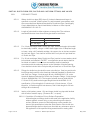
Fine aggregate shall be graded approximately within the limits shown in the
following table. If not enough fines are available in the natural sands,
limestone dust, or other approved fines shall be added:
Per Cent Passing Standard Square Mesh Screens
No. 4
95-100
No. 20
45-80
No. 50
10-30
No. 100
5-10
201.3.3
Coarse aggregate shall consist of the best available crushed limestone or
other approved material. River gravel or other material with smooth surfaces
shall not be used without specific written approval of the Engineer. Coarse
aggregate shall be clean, tough, sound, durable rock and shall not contain
harmful quantities of foreign materials and must be satisfactory to the
Engineer.
201.3.4
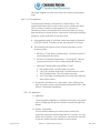
Coarse aggregate shall be graded approximately within the limits shown in
the following table:
Percent Passing Standard Square Mesh Screens
Aggregate
Max Size
2"
1 %"
%"
2%"
100
2"
95-100
100
1 %"
60-95
95-100
1"
50-83
100
Ok"
40-70
40-70
95-100
%"
20-40
3/8"
10-30
40-75
N0.4
0-5
0-5
0-5
201.3.5
Coarse aggregate shall conform to Standard Specifications for Concrete
Aggregates, ANSllASTM C33, except as to graduation. The maximum size
aggregate to be used in structures six inches thick and under shall be threequarters inch; in structures from six inches to ten inches thick, the maximum
size of aggregate shall be one and one-half inches. If required, the
Contractor shall furnish test certificates showing the aggregates meet the
above requirements.
201.3.6
In case the concrete resulting from the mixture of the aggregates is not of a
workable character or does not make the proper finished surface, the
Engineer may require a different grading in order to secure the desired
results, or they may allow the use of inert admixtures to correct deficiencies,
upon proper showing that such use will not materially lower the strength or
increase the permeability of the concrete.
201.4
201.4.1
Page 5 of 39
STEEL REINFORCEMENT
All reinforcing steel shall be deformed bars and shall conform to the
requirements of the Standard Specifications for Deformed and Plain Billet
Steel Bars for Concrete Reinforcement, ANSllASTM A615, for grade 40 or
grade 60. All steel shall be manufactured in the United States.
Division II - Material Specifications
May 2005
201.4.2
201.5
The Engineer reserves the right to require a test of three specimens of each
size of bar from each carload received. These tests shall be made by a
laboratory or testing firm approved by the Engineer and the cost of such
testing shall be included in the price bid for steel reinforcement.
STRENGTH AND PROPORTION
201.5.l
The concrete shall have a compressive strength of not less than 3500 PSI,
unless otherwise specified in the plans, as determined from test cylinders at
twenty-eight days, made, cured, and broken, as hereinafter specified.
201.5.2
The concrete shall be mixed in the approximate proportion of 1 :2-1/2:4-1/4 and
shall contain not less than 6 sacks of cement per cubic yard of finished
concrete. With the approval of the Engineer, admixtures may be added in
order to increase workabi lity.
201.6
TESTING OF CONCRETE
201.6. l
During the progress of the work, a reasonable number of compression tests
shall be made when and if required by the Engineer. Each test shall consist
of not less than three test cylinders. At least one test shall be made for each
one hundred cubic yards of concrete placed. The test cylinders shall be
made and stored in accordance with the Standard Method of Making and
Curing Concrete Test Specimens in the Field, ANSllASTM C31, and shall be
tested in accordance with the requirements relating to making compression
tests on concrete test specimens as given in the Standard Test Method for
Compressive Strength of Cylindrical Concrete Specimens, ANSl/ASTM C39.
201.6.2
All test specimens shall be kept as near to the point of sampling as possible
and yet receive the same protection from the elements as is given to the
portions of the structure being built. Specimens shall be protected from
injury. They shall be sent to a testing laboratory approved by the Engineer
not more than seven days prior to the time of the test, and while in the
laboratory shall be kept in the ordinary air at a temperature of approximately
70 degrees Fahrenheit until tested.
201.6.3
The Contractor shall furnish the Engineer certified reports on these tests. All failed
tests and shall be paid by the contractor.
201.7
RESPONSIBI LITY OF CONTRACTOR FOR STRENGTH
201.7.1
It is the intent of these specifications that the Contractor shall guarantee that
concrete of the specified compressive strength is incorporated in the
structures and that the responsibility for producing the required grades of
concrete is assumed by the Contractor.
201.7.2
Should the average strengths shown by test cylinders fall below the strengths
required, the Engineer will require any or all of the following changes: amount
Page 6 of 39
Division II - Material Specifications
May 2005
of cement, grading of aggregate , or ratio of the water to the cement used. If
the tests disclose that the strength of the concrete is insufficient for the
structure as built, the Engineer may condemn the part of any structure in
which concrete of insufficient strength has been placed and the Contractor, at
his cost, shall remove and replace such concrete with concrete meeting these
specifications.
201.8
201.8.1
201.9
201.9.1
201.10
EXPERIMENTAL CONCRETE MIXES
The Contractor shall make experimental mixes prior to the placing of the
concrete and at any time during the progress of the work when necessary to
demonstrate that the concrete will meet these specifications. Materials for
making experimental mixes shall be furnished by the Contractor and these
materials shall be identical with those intended for use in the work . The cost
of the materials, as well as the costs of crushing test specimens made from
the experimental mix, shall be borne by the Contractor and shall be included
in the price bid for concrete.
MIXING
The concrete shall be mixed in an approved batch machine or mixer. The
ingredients shall be accurately measured by weight, unless measurement by
volume is permitted by the Engineer, before being placed in the mixer.
Measuring boxes or other approved measuring apparatus shall be such that
the proportions can be accurately determined. The quantity of water to be
added, which will vary with the degree of dryness of the material and with the
weather conditions, shall be accurately measured for each batch of concrete.
Means shall be provided by which a measured quantity of water can be
introduced at any stage of the process. The mixing shall be done in a
thorough and satisfactory manner and shall continue until every particle of
aggregate is completely covered with mortar. The mixing time for each batch
shall not be less than one minute after the materials are in the mixer. The
entire contents of the drum shall be discharged before recharging.
Retempering of concrete, which has partly hardened, will not be permitted.
CONSISTENCY
201.10.1 All reinforced concrete which is required to be spaded or puddled in forms or
around reinforcing steel shall be of such consistency that: all aggregate will
float uniformly throughout the mass without settling or segregation; when
dropped directly from the discharge chute of the mixer, it will flatten out at the
center of the pile but will stand up at the edges, the pile spreading from
internal expansion and not by flowing; it will flow sluggishly when tamped or
spaded; it can be readily puddled into corners and angles of forms and
around reinforcing steel, it can be readily spaded to the bottom of the pour or
to a depth of several feet any time within thirty minutes after placing.
Page 7 of 39
Division II - Material Specifications
May 2005
201.10.2
A desirable consistency is one which results in a very slight accumulation of
water at the top of a layer several feet in thickness, but not with segregation
or accumulation of laitance.
201.10.3
If, through accident, intention, or error in mixing, any concrete shall, in the
opinion of the Engineer, vary materially from the consistency specified, such
concrete shall not be incorporated in the work but shall be discharged as
waste material at a location approved by the Engineer.
201.11
PLACING CONCRETE
201.11.1
Before beginning a run of concrete, surfaces of the forms, reinforcing steel,
and concrete previously placed, shall be thoroughly cleaned of hardened
concrete and foreign materials. Forms shall be thoroughly wetted or oiled.
201.11.2
Concrete shall be placed in the forms immediately after mixing. It shall be
deposited so that the aggregates are not separated. Dropping the concrete
any considerable distance, generally in excess of five feet, depositing large
quantities at any point and running or working it along the forms, or any other
practice tending to cause segregation of the ingredients, will not be allowed.
It shall be compacted by vibration or continuous tamping, spading, or slicing.
Care shall be taken to fill every part of the forms, to work the coarser
aggregate back from the face, and to force the concrete under and around the
reinforcement without displacing it. All concrete shall be thoroughly vibrated,
except where specifically excepted in the specifications. The concrete shall
be deposited in continuous horizontal layers and, whenever practicable,
concrete in structures shall be deposited continuously for each monolithic
section of the work. Chutes and tremies used for conveying concrete shall be
mortar-tight.
201.11.3 Work shall be arranged in order that each part of the work shall be poured as
a unit, if this is possible. Where necessary to stop pouring concrete, the work
shall be brought up in level courses and against a vertical stop board.
201.11.4
201.12
The placing of concrete under water, where permitted, must be done by
special approved methods.
PLACING IN COLD WEATHER
201.12.1
No concrete shall be placed without the specific permission of the Engineer
when the air temperature is at or below thirty-five degrees Fahrenheit.
201.12.2
If concreting in freezing weather is permitted by the Engineer, care shall be
taken to prevent the use of any frozen material. In addition to adequate
provision for protecting the concrete against chilling or freezing, the
Contractor shall be required to heat the water and aggregate in order that
when deposited in the forms, the concrete will have a temperature of not less
than fifty degrees Fahrenheit, nor more than eighty degrees Fahrenheit. The
concrete shall be adequately protected in order to maintain this temperature
Page 8 of 39
Division II - Material Specifications
May 2005
for a minimum of seventy-two hours after it has been placed and a
temperature above thirty-two degrees Fahrenheit for a period of two
additional days. The work shall be done entirely at the Contractor's risk.
201.12.3
201.13
No chemicals or other foreign matter shall be added to the concrete for the
purpose of preventing freezing.
READY-MIXED CONCRETE
201.13.1
Ready-mixed concrete may be used on the work, with the approval of the
Engineer, when the Contractor can demonstrate that the concrete can be
furnished in accordance with the specifications hereinabove and that delivery
can be made at such rate as will insure the continuity of any pour. Standard
Specifications for Ready-Mix Concrete, ANSl/ASTM C94, when not in conflict
with the specifications herein, shall control the furnishing of ready-mix
concrete.
201.13.2
All mixer trucks shall be equipped with water meters. Additional water shall
be added at the job site only with the specific approval of the Engineer.
201.14
CONSTRUCTION JOINTS
201.14.1
Construction joints shall be located as shown on the drawings and at other
points as may be necessary during the construction, provided that the
location and nature of additional joints shall be approved by the Engineer. In
general, joints shall be located at points of minimum shear, shall be
perpendicular to the principal lines of stress, and shall have suitable keys
having areas of approximately one-third of the area of the joints.
201.14.2
In resuming work, the surface of the concrete previously placed shall be
thoroughly cleaned of dirt, scum, laitance, or other soft material, and shall be
roughened. The surface shall then be thoroughly washed with clean water
and covered with at least one-half inch of cement mortar, after which
concreting may proceed. Mortar shall be placed in a manner in order not to
splatter forms and reinforcing steel.
201.15
FINISH OF CONCRETE SURFACES
201.15.1
All surfaces exposed to view shall be free from conspicuous lines, affects, or
other irregularities caused by defects in the forms . If for any reason this
requirement is not met, or if there are any conspicuous honeycombs, the
Engineer may require the correction of the defects by rubbing with
carborundum bricks and water until a satisfactory finish is obtained.
201.15.2
Immediately after removing the forms, all wires or other exposed metal shall
be cut back of the concrete surface, and the depressions thus made and all
honeycombs and other defects shall be pointed with mortar and then rubbed
smooth. If the Engineer deems any honeycomb or other defect to require
such treatment, the defective concrete shall be cut out to a depth sufficient to
Page 9 of 39
Division II - Material Specifications
May 2005
expose the reinforcement and to afford a key for the concrete replacing that
cut out.
201.16
CURING CONCRETE
201.16.1 Exposed surfaces of concrete shall be protected by approved methods from
premature drying for a period of at least seven days. Curing compounds ,
when approved by the Engineer, shall be applied according to the
manufacturer's recommendations. The Engineer may require the frequent
wetting of the concrete and/or forms and the use of means to protect it from
the direct rays of the sun.
201.17
PLACING REINFORCEMENT
201.17.1 All reinforcement, when placed, shall be free from mill scale, loose or thick
rust, dirt, paint, oil or grease, and shall present a clean surface. Bends and
splices shall be accurately and neatly done and shall conform to American
Concrete Institute Manual of Standard Practice for Detailing Reinforced
Concrete Structures.
201.17.2 All reinforcing shall be placed in the exact position shown on the drawings
and shall be held firmly in position by means of approved metal spacers and
supports, by wiring to the forms, and by wiring the bars together at
intersections with approved wire ties in order that the reinforcement will not be
displaced during the depositing and compacting of the concrete. The placing
and fastening of reinforcement in each section of the work shall be approved
by the Engineers before any concrete is deposited in the section. Care shall
be taken not to disturb the reinforcement after the concrete has taken its initial
set.
201.18
FORMS
201.18.1 Forms shall be so designed and constructed that they may be removed
without injuring the concrete. The material to be used in the form for exposed
surfaces shall be sized and dressed lumber or metal in which all bolt and rivet
heads are countersunk. In either case, a plain, smooth surface of the desired
contour must be obtained. Undressed lumber may be used for backing or
other unexposed surfaces, except inside faces of conduit.
201.18.2 The forms shall be built true to line and braced in a substantial and unyielding
manner. They shall be mortar-tight, and if necessary to close cracks due to
shrinkage, shall be thoroughly soaked in water. Forms for re-entrant angles
shall be filleted, and for corners shall be chamfered. Dimensions affecting the
construction of subsequent portions of the work shall be carefully checked
after the forms are erected and before any concrete is placed. The interior
surfaces of the forms shall be adequately oiled with a non-staining mineral oil
to insure the non-adhesion of mortar.
Page IO of 39
Division II - Material Specifications
May 2005
201.18.3
Form lumber, which is to be used a second time, shall be free from bulge or
warp and shall be thoroughly cleaned. The forms shall be inspected
immediately preceding the placing of concrete. Any bulging or warping shall
be remedied, and all dirt, sawdust, shavings, or other debris within the forms
shall be removed. No wood device of any kind used to separate forms will be
permitted to remain in the finished work.
201.18.4
Temporary openings shall be placed at the bottom of the column and wall
forms and at other points where necessary to facilitate cleaning and
inspection immediately before depositing concrete.
201.19
REMOVAL OF FORMS
201.19.1
Forms shall be removed in such manner as to insure the complete safety of
the structure . No forms shall be removed except with the express approval of
the Engineer. In general, this approval will be based on the following:
201.19.2
Forms on ornamental work, railings, parapets, and vertical surfaces which do
not carry loads and which will be exposed in the finished work shall be
removed within twenty-four to forty-eight hours after placing, depending upon
weather conditions.
201.19.3
Girder, beam, and joist sides only, column, pier, abutment, and wall forms
may be removed within twenty-four to forty-eight hours after placing,
depending upon weather conditions. No backfill shall be placed against walls,
piers, or abutments, unless they are adequately supported or have reached
the required strength.
201.19.4
Girder, beam, and joist soffit forms shall remain in place with adequate
shoring underneath, and no construction load shall be supported upon, nor
any shoring removed from any part of the structure under construction until
that portion of the structure has attained sufficient strength to support safely
its weight and the loads placed thereon.
PART 202 - QUICK-SETTING FLOWABLE FILL
202 .1
202.1.1
MATERIALS
Quick-setting flowable fill shall be a sand-cement slurry consisting of the
following materials in a one cubic yard mixture:
Sand
Water
Page 11 of 39
Division II - Material Specifications
May 2005
202.1.2
NOTE: Can change somewhat due to type of sand used.
202.1.3
The combination of materials above shall be mixed in a ready-mix truck to
produce the sand-cement slurry mixture.
202.1.4
Submittals shall be delivered to the City of Tulsa at a date set by the
Engineer. Submittals shall include the items outlined in ODOT Specification
701.03.
202.2
CONSTRUCTION METHODS
202.2.1
For each cubic yard of quick-setting flowable fill material required, the amount
of the mix components in the MATERIALS section shall be used to produce
the sand-cement slurry mixture. The slurry mixture shall be mixed between
70 to 100 revolutions of the ready-mix truck.
202.2.2
To minimize segregation, all flowable fill material shall be re-mixed at the
project site at mixing speed in the ready-mix truck for approximately two
minutes immediately prior to discharge of the sand-cement slurry mixture.
Re-mixing of the flowable fill slurry shall be done under the direction of the
Engineer.
202.3
TESTING
202.3.1
Special Provisions, "Flowable Fill Testing Procedures" identifies the Ohio
Ready-Mixed Concrete Association (ORMCA) Standards FF1(94), and
FF4(94) which shall be used in the performance of field testing.
202.3.2
The following are the testing requirements for the quick-setting flowable fill:
Flow
Compressive Strength (28
days)
= 4 Yi " inches
Minimum = 25 pounds per square inch
Minimum
(psi)
Maximum
(psi)
202.4
202.4.1
Page 12 of 39
= 60 pounds per square inch
GENERAL
The time required before placing pavement over the cured quick-setting
flowable fill is a minimum of six hours and/or whenever a minimum
penetration value of 400 pounds per square inch (psi) is achieved.
Penetrometer readings shall be taken with a Soiltest Mortar Penetrometer,
Model CT -421A, or approved equal. The upper three inches of the area of
the cured flowable fill mixture to be tested shall be removed prior to taking the
penetrometer readings. The test value of record shall be the average of three
tests.
Division II - Material Specifications
May 2005
PART 203 .DUCTILE IRON PIPE, DUCTILE AND CAST IRON FITTINGS, AND VALVES
203.1
PIPE AND FITTINGS
203.1.1
Where ductile iron pipe (DIP) three (3) inches in diameter and larger is
specified or required, it shall conform to, and be tested in accordance with,
the current American National Standard for Ductile Iron Pipe, Centrifugally
Cast in Metal Molds or Sand-Lined Molds, for Water or Other Liquids,
ANSllAWWA C151/A21.51.
203.1.2
Length of joints shall be either eighteen or twenty feet. The minimum
standard thickness class of each size pipe shall be as follows:
Pipe Size
4" thru 8"
1O" and larger
Thickness Class
51
50
203.1.3
For 16-inch and larger Water Ductile Iron Pipe, all bell and spigot joints shall
be electrically bonded, using a #4 AWG bare copper wire of adequate length
to braze, using a #15 cadweld cartridge, the copper wire to the bare metal at
the bell and spigot. Cost shall be included in the unit price bid per lineal foot
of Ductile Iron Pipe.
203.1.4
For 16-inch and larger Water Ductile Iron Pipe, junction box test stations shall
be furnished and installed, EXCEPT, no magnesium anode banks shall be
furnished or installed. Junction box test stations shall be installed in
accordance with the stationing shown on the Schedule of Anode Spacing.
Cost shall be included in the unit price bid per lineal foot of Ductile Iron Pipe.
203.1.5
Fittings for ductile iron pipe shall be cast or ductile iron. Cast iron and ductile
iron fittings shall conform to the American National Standard for Ductile-Iron
and Gray-Iron Fittings, 3-inch through 48-inch, ANSllAWWA C110; or the
American National Standard for Ductile-Iron Compact Fittings, 3-inch through
48-inch, ANSllAWWA C153. The length of all solid sleeves (both AWWA
C110 and C153) shall be the longest length listed in the AWWA C110
specification (12-inch length for 3-inch through 12-inch sleeves, 15-inch
length for 14-inch through 24-inch sleeves, and 24-inch length for 30-inch
through 48-inch sleeves).
203.1.6
Interior of all sanitary sewer 15-in and larger ductile iron pipe shall be lined
with 40 mils of ceramic epoxy ("Protecto 401", or equal).
203.1.6.1 Condition of Ductile Iron Prior to Surface Preparation.
All ductile pipe and fittings shall be delivered to the application facility
without asphalt, cement lining, or any other lining on the interior
surface. Because removal of old linings may not be possible, the
intent of this specification is that the entire interior of the ductile iron
pipe and fittings shall not have been lined with any substance prior to
the application of the specified lining material and no coating shall
Page 13 of 39
Division II - Material Specifications
May 2005
have been applied to the first six inches of the exterior of the spigot
ends.
203.1.6.2 Lining Material.
The Standard of Quality is Protecto 401 Ceramic Epoxy. The
material shall be an amine cured novalac epoxy containing at least
20% by volume of ceramic quartz pigment. Any request for
substitution must be accompanied by a successful history of lining
pipe and fittings for sewer service, a test report verifying the following
properties, and a certification of the test results.
A. A permeability rating of 0.00 when tested according to Method A
of ASTM E-96-66, Procedure A with a test duration of 30 days.
B. The following test must be run on coupons from factory lined
ductile iron pipe:
1. ASTM 8-117 Salt Spray (scribed panel) - Results to equal 9.0
undercutting after two years
2. ASTM G-95 Cathodic Disbondment 1.5 volts @ 7rF. Results
to equal no more than 0.5mm undercutting after 30 days.
3. Immersion Testing rated using ASTM 0-714-87.
a. 20% Sulfuric Acid - No effect after two years.
b. 140°F 25% Sodium Hydroxide - No effect after two years.
c. 160°F Distilled Water - No effect after two years.
d. 120°F Tap Water (scribed panel) 0.0 undercutting after two
years with no effect.
C. An abrasion resistance of no more than 3 mils (.075mm) loss
after one million cycles using European Standard EN 598: 1994
Section 7.8 Abrasion Resistance.
203.1.6.3 Application
A. Applicator
The lining shall be applied by a competent firm with a successful
history of applying linings to the interior of ductile iron pipe and
fittings.
B. Surface Preparation
Prior to abrasive blasting, the entire area to receive the
protective compound shall be inspected for oil, grease, etc. Any
areas with oil, grease, or any substance which can be removed
by solvent, shall be solvent cleaned to remove those
Page 14 of 39
Division
II - Material Specifications
May 2005
substances. After the surface has been made free of grease, oil
or other substances, all areas to receive the protective
compounds shall be abrasive blasted using sand or grit abrasive
media. The entire surface to be lined shall be struck with the
blast media so that all rust, loose oxides, etc., are removed from
the surface. Only slight stains and tightly adhering oxide may
be left on the surface. Any area where rust reappears before
lining must be reblasted.
C. Lining
After the surface preparation and within 8 hours of surface
preparation, the interior of the pipe shall receive 40 mils nominal
dry film thickness of Protecto 401. No lining shall take place
when the substrate or ambient temperature is below 40 degrees
Fahrenheit. The surface also must be dry and dust free. If
flange pipe or fittings are included in the project, the lining shall
not be used on the face of the flange.
D. Coating of Bell Sockets and Spigot Ends
Due to the tolerances involved, the gasket area and spigot end
up to 6 inches back from the end of the spigot end must be
coated with 6 mils nominal, 10 mils maximum using Protecto
Joint Compound. The Joint Compound shall be applied by
brush to ensure coverage. Care should be taken that the Joint
Compound is smooth without excess buildup in the gasket seat
or on the spigot ends. Coating of the gasket seat and spigot
ends shall be done after the application of the lining.
E. Number of Coats
The number of coats of lining material applied shall be as
recommended by the lining manufacturer. However, in no case
shall this material be applied above the dry thickness per coat
recommended by the lining manufacturer in printed literature.
The maximum or minimum time between coats shall be that
time recommended by the lining material manufacturer . To
prevent delamination between coats, no material shall be
used for lining which is not indefinitely recoatable with
itself without roughening of the surface.
F . Touch-Up & Repair
Protecto Joint Compound shall be used for touch-up or repair in
accordance with manufacturer's recommendations.
Page 15 of 39
Division
II - Material Specifications
May 2005
203.1.6.4 Inspection and certification
A Inspection
1. All ductile iron pipe and fitting linings shall be checked for thickness
using a magnetic film thickness gauge. The thickness testing shall
be done using the method outlined in SSPC-PA-2 Film Thickness
Rating.
2. The interior lining of all pipe barrels and fittings shall be tested for
pinholes with a nondestructive 2,500 volt test. Any defect found
shall be repaired prior to shipment.
3. Each pipe joint and fitting shall be marked with the date of
application of the lining system along with its numerical sequence
of application on that date and records maintained by the applicator
of his work.
B. Certification
The pipe or fitting manufacturer must supply a certificate attesting to
the fact that the applicator met the requirements of this specification,
and that the material used was a specified.
203.1.6.5 Handling
Protecto 401 lined pipe and fittings must be handled only from the
outside of the pipe and fittings. No forks, chains, straps, hooks, etc.
shall be placed inside the pipe and fittings for lifting, positioning, or
laying.
203.2
JOINTS
203.2.1
Cast iron and ductile iron pipe and fittings shall be jointed with any of the end
types as specified below, unless a particular end type is specified. Fittings
shall have mechanical joints, unless otherwise specified. Flanged ends shall
be used only where specifically noted on the Drawings except that the valve
connection end of all tapping sleeves shall be flanged.
203.2.2
Mechanical joints and push-on joints shall conform to, and be tested in
accordance with, the American National Standard for Rubber Gasket Joints
for Ductile-Iron and Gray-Iron Pressure Pipe and Fittings, ANSl/AWWA
C 1111 A21 .11 .
203.2.3
Flange joints shall conform to the American National Standard for Cast Iron
Pipe Flanges and Flanged Fittings, ANSI 816.1.
203.2.4
Where ductile or cast iron pipe is to be tapped, a split case iron or a flexible
stainless steel tapping sleeve may be used.
Page 16 of 39
Division 11- Material Specifications
May 2005
203.2.5
Split case iron tapping sleeves shall be of 150 psi working pressure. Sleeve
body shall be cast iron conforming to ANSllAVWVA C11 0. Sleeve shall have
mechanical joints conforming to AVWVA C111 on the run and a flange branch
conforming to ANSI 816.1, Class 125. End gaskets shall be natural rubber or
neoprene material conforming to ANSllAVWVA C111.
203.2.6
6
203.2.7
Openings of the sizes shown on the drawings shall be furnished with steel
blind flanges of proper strength to withstand working pressure of the line
where no other provision is made for closing the openings. Blind flanges shall
be fabricated from material as specified under ANSllAVVWA C200. All bolts
shall be carbon steel ANSl/ASTM A307, Grade A only, in accordance with
ANSllAVVWA C207.
203.2.8
Where restrained joints are specified or required, they shall be of a
mechanical type or push-on type assembly easily removed in field once
assembled without special equipment. Assemblies shall be ANSllAVWVA
rated. Set screw type retainer glands will not be permitted.
203.3
Flexible stainless steel tapping sleeves shall be rated at 150
psi pressure, with flanges meeting AVWVA C207. Assembly shall be
NSF or UL rated. Bolts, nuts, and washers shall be stainless steel.
Gaskets shall conform to ANSllAVVWA C111.
COATING, LINING AND POLYETHYLENE WRAP
203.3.1
Cast iron and ductile iron pipe and fittings shall be bituminous coated outside
and cement-mortar lined inside with seal coat in accordance with American
National Standard for Cement Mortar Lining for Ductile-Iron and Gray-Iron
Pipe and Fittings for Water, ANSllAVVWA C1 04/A21.4.
203.3.2
All ductile iron and cast iron pipe and fittings shall be encased with
polyethylene tube in accordance with AVWVA C105, American National
Standard for Polyethylene Encasement for Ductile Iron Piping for water and
other liquids. Polyethylene film shall be manufactured of virgin polyethylene
material conforming to ASTM 0-1248, Type 1, Class A or C, Grade E.
Thickness shall be not less than 8 mils (0.008 in.). Tensile strength shall be
1200 psi, minimum. Elongation shall be 300 percent, minimum. Tube length
shall provide at least one (1) foot of overlap at each joint of pipe. Tape shall
be a 2" width, plastic backed adhesive tape, Polykan #900, Scotch #50, or
equal. Tube width for each pipe diameter shall be as follows:
Page 17 of 39
Division - Material Specifications
May 2005
NOMINAL
PIPE SIZES
4"
6"
8"
10"
12"
14"
16"
18"
20"
24"
30"
36"
203.4
PUSH-ON JOINT
FLAT
TUBE WIDTH
14"
17"
21"
25"
29"
33"
37"
41"
45"
53"
67"
81"
MECHANICAL JOINT
FLAT
TUBE WIDTH
16"
20"
24"
27"
30"
34"
37"
41"
45"
53"
67"
81"
GATE VALVES
203.4.1
Where gate valves are specified, they shall be resilient-wedged .
203.4.2
Resilient-wedged gate valves shall conform to and be tested in accordance
with ANSllAWWA C509. The valve shall be bubble tight from either direction
at the rated design pressure of 200 psi. The valve shall have a single disc
gate with synthetic rubber seat bonded or mechanically attached to the disc;
non-rising stem with 2-inch AWWA operating nut; counter clockwise opening,
"O" ring stem seals, and corrosion resistant interior coating acceptable for
potable water use.
203.4.3
3 Where specified, flanges shall be ANSI B16.1, Class 125, cast
iron. Mechanical Joint, push-on, and bell and spigot joints are
allowed.
203.5
BALL VALVES
203.5.1
Ball valves shall conform to and be tested in accordance with the AWWA
Standard for Ball Valves, ANSllAWWA C507. Where ball valves are specified
or required, they shall be: double-seated with natural or synthetic rubber
located in the valve body. Ball seating surfaces shall be stainless steel;
designed for 150 psi working pressure; flanged end; "O" ring rotor bearing
seals; constructed of high-tensile strength cast iron; counter-clockwise
opening; equipped with totally enclosed manual operators, and torque limiting
control device. Valves shall be tested by, and shall withstand without leak, a
hydrostatic pressure of: (1) 250 psi on the valve body with rotor in the open
position; and (2) 150 psi on the side of the valve with the opposite side open
to atmosphere. Six (6) copies of the test results and manufacturer's drawings
shall be submitted for approval prior to delivery of the valve.
203.5.2
Valves shall be bubble tight at rated pressure with flow in either direction.
Page 18 of 39
Division II - Material Specifications
May 2005
203.5.3
203.6
Where flanges are specified, they shall be ANSI 816.1, Class 125, cast iron
flanges.
BUTIERFL Y VALVES
203.6.1
Butterfly valves shall be of the tight-closing, rubber-seat type, shall have a
rated pressure of 150 psig, and shall be bubble-tight at this pressure with flow
in either direction. Valve opening shall be counter-clockwise. The valves shall
conform to and be tested in accordance with the AWWA Standard for RubberSeated Butterfly Valves, ANSllAWWA C504, Class 1508. The valve body
shall be of the short-body flange type, constructed of cast iron conforming to
either ASTM A126, Class B, or ANSllASTM A48, Class 40 or ductile iron
ANSIIASTM A536, Grade 65-45-12. Flanges shall be ANSI B 16.1, Class
125, cast iron flanges. Valve Discs shall be constructed of alloy cast iron
conforming to ANSllASTM A436, Type 1, or cast iron conforming to
ANSllASTM A48, Class 40, or ductile iron ANSllASTM A536, Grade 65-4512. Valve shafts shall be constructed of 18-8, Type 304 or 316 stainless
steel, ANSllASTM A296, Grade CF8, or monel. Valve seats shall be body
mounted and shall be of natural or synthetic rubber compound with mating
seat surfaces of 18-8, Type 304 or 316 stainless steel, or alloy cast iron
conforming to ANSl lASTM A436, Type 1, or bronze Grade A, 0, or E. Valve
bearings shall be corrosion resistant and self-lubricating.
203.6.2
Interior surfaces of the valve, except seating surfaces, shall be epoxy coated
in accordance with AWWA Standard for Protective Interior Coatings for
Valves and Hydrants, AWWA C550. Exterior surface of the valve shall be
painted with two (2) coats of asphalt varnish conforming to Federal
Specifications Tl-V-51C. For non-buried service, exterior surface shall be
coated with two (2) coats of epoxy, not zinc chromate.
203.6.3
Performance, hydrostatic and leakage tests shall be conducted in strict
accordance with ANSllAWVVA C 504, except that the leakage tests as
outlined in Section 5.3 are to be conducted on both faces of the disc.
203.6.4
Six (6) certified copies of the manufacturers detail drawings shall be
submitted for approval prior to delivery of the valve.
203.6.5
Six (6) certified copies of the test results, signed by a registered professional
engineer, are to be furnished to the Engineer.
203.7
203.7.1
Page 19 of 39
MANUAL OPERATORS FOR BALL VALVES AND BUTIERFLY VALVES
Manual Operators for Ball and Butterfly valves shall be totally enclosed,
permanently lubricated, counter-clockwise opening, and designed for buried
or submerged service. Manual Operators shall be equipped with a 2" square
AWWA operating nut with a removable handwheel complete with spinner and
an open-Closed indicator, suitable for one-man operation at 150 psi
unbalanced across the valve. Manual Operators shall be either worm gear or
Division II - Material Specifications
May 2005
traveling-nut type, and shall conform to AWWA C507 for Ball Valves or
AWWA C504 for Butterfly Valves.
203.7.2
203.8
203.8.1
203.9
203.9.1
203.10
203.10.1
Page 20 of 39
Manual Operators for Ball and Butterfly Valves 16" and larger shall be
equipped with a Torque Limiting Control Device. The device shall be
mounted directly on the operating nut for valves in vaults and on top of the
extension shaft for buried valves. The device shall be secured to the
operating nut with two setscrews. The device shall dedutch at 200 lb-ft of
input torque in either direction of rotation. The device shall be designed for
permanent buried or submerged service. Declutch and reset shall be
automatic. Repeatability shall be within 5 percent of original rating for a
minimum of 1000 cycles. Certified proof-of-design test reports shall be
furnished for the device.
AIR RELIEF VALVES
Where air relief valves are specified or required, the valve shall be heavy-duty
combination air release and vacuum type for 150 psi working pressure, tested
to 300 psi, size shown on plans. Body, cover, and baffle shall be cast iron.
All internal parts to be either highest quality stainless steel or bronze, and the
inside of valve coated with rust inhibitor.
CHECK VALVES
Where check valves are specified or required, they shall conform to, and be
tested in accordance with the AWWA Standard for Swing-Check Valves for
Ordinary Water Works Service, AWWA C508. They shall be horizontally
mounted, single disc, swing type with a full diameter passage providing
minimum pressure loss. Valves shall be of the non-slamming type designed
for the future installation of outside lever and weight. Unless otherwise
specified, all check valves installed in pump or lift stations shall be equipped
with position indicator. Disk shall be coated rubber and body shall be epoxy
coated. Ends shall fit the pipe or fitting to which attached (push-on,
mechanical, bell and spigot, or flanged).
3-WAY FIRE HYDRANTS
Where fire hydrants are specified, they shall conform to, and be tested in
accordance with the AWWA Standard for Dry-Barrel Fire Hydrants,
ANSllAWWA C502. All hydrants shall have: breakable connection features
and a breakable coupling on the stem immediately above the bury line which
has a lower breaking point than the rest of the unit; 5 1/4 -inch compression
main valve; 6-inch inlet connection; standard bell or mechanical joint hub;
four-foot six-inch bury length, or as specified on drawings; two 2 1/2-inch hose
nozzles with National Standard threads; one 4-inch pumper nozzle with City
Standard threads (refer to attached Standard Detail for Fire Hydrants); "O"
ring seal; drain valve; left (counter-clockwise) opening; Federal yellow finish
paint above ground line; and National Standard pentagon operating nut.
Division II - Material Specifications
May 2005
,---------·-·
203.10.2
203.11
Where fire hydrant extensions are specified or required, they shall be of
proper design to accommodate the make of fire hydrant installed.
FOUR-WAY FIRE HYDRANT
203.11.1
Where four-way fire hydrants are specified or required, they shall conform to,
and be tested in accordance with the AWWA Standard for Dry-Barrel Fire
Hydrants, ANSl/AWWA C502. All hydrants shall have: breakable connection
features and a breakable coupling on the stem immediately above the bury
line which has a lower breaking point than the rest of the unit; 8-inch inlet
connection; bell, flange, or mechanicaljoint inlet; four-foot six-inch bury
length; two 2 1/2-inch hose nozzles with National Standard threads; two 4-inch
pumper nozzles with Tulsa Standard threads; "O" ring seal; drain valve; left
(counter-clockwise) opening; Federal yellow finish paint above ground line;
and National Standard pentagon operating nut.
203.11.2
Where fire hydrant extensions are specified or required, they shall be of the
proper design to accommodate the make of fire hydrant installed.
203.12
203.12.1
BLOW-OFF HYDRANT
Where blow off hydrants are specified or required, they shall be
constructed in accordance with Construction Standard Blow-off Hydrant.
1
PART 204 - STEEL PIPE AND FITTINGS
204.1
204.1.1
GENERAL
Where steel pipe is specified or required, it shall conform to the AWWA
Standard for Steel Water Pipe, 6-lnches and Larger, AWWA C200. No steel
less than 33,000 psi specified minimum yield strength shall be permitted. All
pipe shall be hydrostatically tested in accordance with AWWA C200. Mill
Test Reports shall be furnished and the hydrostatic test pressure shown on
shop fabrication drawings. AWWA Designation C200 shall govern the testing.
Pipe length shall be not less than 35 feet per joint, except for specials, unless
otherwise noted. There shall be no more than one longitudinal or girth seam
per section. Nominal pipe diameter and steel thickness shall be as specified
on the drawings. The diameter shown is the required inside diameter of
cement-mortar lining. All pipe shall be manufactured by an established
manufacturer who has had at least three (3) years experience in successfully
building this type of pipe. Openings for air valves, main connections, and
blow-off connections shall be provided with suitable reinforcements around
the opening, welded to the body of the pipe in accordance with AWWA
Manual M11. Openings of the sizes shown on the drawings shall be furnished
with steel blind flanges of proper strength to withstand the working pressure
of the line where no other provision is made for closing the openings. Blind
flanges shall be fabricated from material listed above as specified under
AWWA C200. All bolts shall be carbon steel ANSllASTM A307, Grade A
Page 21 of 39
Division II - Material Specifications
May 2005
only, in accordance with ANSl/AWWA C207. For corrosion monitoring of
steel pipe, junction box test stations shall be furnished and installed.
Magnesium anode banks shall be furnished and installed where specified in
the plans. Junction box test stations and anode banks shall be installed in
accordance with the stationing as shown on the Schedule of Anode Spacing
in the plans.
204.1.2
All steel pipe shall be manufactured with ends of true circular shape, free from
indentations, projections, or roll marks for a distance of eight inches (8") from
the end of the pipe. This shall be done by hydraulic expansion or some other
method satisfactory to the Engineer. The outside diameter of the pipe shall
be true enough in dimension to permit the passage for a distance of eight
inches (8") from the end of the pipe a ring gauge with a bore three-thirty
seconds of an inch larger than the outside diameter of the pipe.
204.1.3
Where steel fittings or specials are specified or required, they shall conform to
all of the steel pipe specification requirements and to the AWWA Standard for
Dimensions for Steel Water Pipe Fittings AWWA C208. Where fittings and
specials are fabricated from mill pipe, they shall be fabricated from pipe
hydrostatically tested in accordance with AWWA C200 with mitered joints dye
checked for welding flaws. Changes in line and grade shall be made by steel
specials or in the joints. Joint deflection shall not exceed that as
recommended by the manufacturer. Inside diameter of steel specials and
fittings shall be the required inside diameter of cement-mortar lining.
204.1.4
Where field cutting of steel pipe is permitted, pipe shall be cut by sawing. The
inside lining shall be removed for a minimum of six inches each side of the cut
and the pipe surface shall be cleaned and brushed to bright metal. After
welding, the inside lining shall be replaced in accordance with AWWA C602.
204.1.5
Minimum thickness of steel pipe shall be 0.25 inches. The minimum
thickness standard in inches for each following size pipe shall be as follows:
Minimum Thickness - Inches for Grade of Steel
Nominal Pipe
Diameter
6"- 30"
A-283 Gr. D
A-570 Gr. 33
36"
42"
48"
54"
60"
66"
72"
0.313
0.313
0.375
0.438
0.500
0.500
0.563
Page 22 of 39
A-53 Gr. B
A-135 Gr. B
A-139 Gr. B
A-36
0.250
0.281
0.313
0.375
0.406
0.438
0.500
Division II - Material Specifications
A-139 Gr. C
A-572 Gr. 42
0.250
0.250
0.281
0.313
0.344
0.375
0.406
May 2005
204.1.6
204.2
The design criteria for steel pipe thickness is based on 150 psi working
pressure plus a 75 psi allowance for water hammer. Maximum depth of cover
shall be 12 feet. Depth of cover in excess of 12 feet shall require special
design.
JOINTS
204.2.l
Steel Pipe and fittings shall have one of the following type joints: slip joint
ends for field lap welding, single beveled ends for field butt welding, double
beveled ends for field butt welding, "O" ring bell and spigot joints, or plain
ends for mechanically coupled field joints. Flange ends shall be used only
when noted on the drawings.
204.2.2
Welded joints shall conform to, and be tested in accordance with the AWStandard for
Field Welding of Steel Water Pipe Joints, AWWA C206. Slip
joints for field lap welding shall be sized to provide a tolerance of not less than
0.09 inches and not more than 0.41 inches difference in measurement
between the outside circumference of the spigot end and the inside
circumference of the bell end.
204.2.3
Mechanically coupled joints shall consist of Dresser Couplings, Style 38, or
equal, or as specified on the drawings. The harness lugs, tie bolts, and nuts
shall conform to AWWA M11 Steel Pipe Design and Installation, Par. 19.8.
204.2.4
Bell and spigot joints with rubber gasket shall conform to the AWWA Standard
for Steel Water Pipe 6-lnches and Larger, AWWA C200 and the AWWA Steel
Pipe Manual, Mil. The gasket shall be a continuous "O" ring design of natural
rubber or neoprene and shall be of suitable cross-section and size to assure a
watertight joint. Acceptable bell and spigot joints for all steel pipe diameters
and thicknesses shall be the "O" Ring-Bar Type, or the "O" Ring-Carnegie
Section, or rolled groove type joint. Bell and spigot ends shall be properly
sized by forcing over a sizing die or by expanding to stretch the steel beyond
its elastic limit so that the difference in diameter between outside of spigot
and inside of bell at normal engagement is not less than .03" and not more
than 0.1O" as measured on circumference with a diameter tape. Shop applied
interior lining on the bell end of the pipe shall be held back a minimum
distance of the spigot engagement + 1-1/8" for the Bar and Carnegie Type
Joints. Hold back for the rolled groove joint shall be the spigot engagement +
%". Interior lining for the spigot, shall be continuous to the end. Field
replacement of the interior joint linings shall be in accordance with Section
203.4. of these specification for cement-mortar linings. All "O" Ring joints
shall be electrically bonded using a #4 bare copper wire, 6" length #15
cadweld cartridge brazed to bare metal at the bell and spigot or equal. Shop
applied exterior coatings shall be held back in accordance with
manufacturer's specifications. Field replacement of exterior coatings at the
joints shall be in accordance with the AWWA Standard for Cold-Applied Tape
Coatings for Special Sections, Connections, and Fittings, for Steel Water
Pipelines, AWWA C209, or A\NVVA C203 Coal-Tar Protective Coatings and
Linings for Steel Water Pipelines, Enamel and Tape, Hot Applied, or AWWA
Page 23 of 39
Division II - Material Specifications
May 2005
C205, Cement-Mortar Protective Lining and Coating for Steel Water Pipe, 4"
and Larger, Shop Applied.
204.2.5
Where steel pipe is to be tapped, a split tapping saddle of 150 psi working
pressure shall be used. The saddle body shall be heavy welded ANSllASTM
A36, or ANSllASTM A285, Gr. C steel with flange conforming to ANSl/AWWA
C207, Class D. The gasket shall be natural rubber or neoprene design in a
continuous ring of suitable cross-section, and sized to assure a watertight
joint. The interior and exterior surfaces of the saddle body shall be shop
coated with a fusion-bonded epoxy. The exterior coating or wrap on steel
pipe shall be removed to bare metal beneath the entire area to be covered by
the sleeve.
204.2.6
Flanged joints shall conform to the AWWA Standard for Steel Pipe flanges,
AWWA C207, Class D.
204.3
EXTERIOR COATING
204.3.1
The exterior coating on steel pipe and fittings shall be in accordance with
Coal Tar Protective Coatings and Linings for Steel Water Pipelines, Enamel
and Tape, Hot Applied, AWWA C203; or Tape Coating Systems for the
Exterior of Water Pipelines, AWWA C214 or cement-mortar coatings in
accordance with AWWA C205, Cement-Mortar Protective Lining and Coating
For Steel Water Pipe, 4" and Larger, Shop Applied. Where tape coatings are
used, the total thickness shall be no less than 80 mils. Where cement-mortar
coating is used, the thickness shall be not less than 3/4" and reinforced with
spiral-wire, wire-fabric, or ribbon mesh reinforcement in accordance with
AWWA C205, Sec. 2.1. A" above ground piping shall be cleaned, primed,
and painted with an enamel, as shown in the plans. The total dry film
thickness shall be 6 mils.
204.3 .2
If field welding is used, the pipe joints shall be furnished with the outside
coating held back, in accordance with standard joint detailed drawings. The
coating and any touch up work shall be done under the direction of the
coating manufacturer , and as approved by the Engineer.
204.4
204.4.1
INTERIOR LINING
The interior lining shall be installed in the field in accordance with AVVWA
C602, Cement-Mortar Lining of Water Pipelines, 4-lnch and Larger, In Place;
or shop applied in accordance with AWWA C205, Cement Mortar Protective
Lining and Coating for Steel Water Pipe, 4" and Larger, Shop Applied. The
lining shall be 3/8" thick for diameters through 36", and 1/2" thick for 42" and
larger, whether shop or in place lined. Tolerances shall be in accordance with
the applicable AWWA standards. Coal-tar enamel and coal tar epoxy interior
linings will not be permitted.
204.4.2
Page 24 of 39
Where in place cement-mortar lining is used, the contractor shall furnish all
materials, labor, equipment, prepare the interior surface, and machine place
Division
n ·Material Specifications
May 2005
the mortar lining in the pipe. The lining at valves, specials, and bends may be
hand sprayed or troweled, or hand applied as required. The lining shall be
maintained in a moist condition while curing. The contractor shall be
responsible for any extended curing time until acceptance by the Engineer.
No additional payment shall be made for any extended curing period.
204.4.3
204.5
204.5.1
Where in-place mortor lining is cracked or delaminated from steel cylinder
pipe, contractor shall repair broken or delaminated areas with Hilti 2-part
epoxy, or approved equal.
STRUTTING AND BRACING
Strutting and bracing shall be provided on all specials, fittings, and straight
pipe, where shop lined or coated with cement mortar, so as to limit the pipe
deflection to 2% maximum of inside diameter. A minimum of three strutting
braces shall be installed in each standard pipe joint. For pipe 54" and larger
in diameter , the strutting shoes at each bearing point shall be minimum 4 feet
long, parallel to the longitudinal pipe axis. The strutting shall remain in place
until all compacting and backfilling has been completed. Where In Place
cement mortar lining is to be installed, sufficient strutting braces subject to the
approval of the engineer, shall be installed at the shop to insure against pipe
deformation.
PART 205 • REINFORCED CONCRETE PIPE AND FITTINGS
205.1
REINFORCED CONCRETE PIPE AND FITllNGS FOR WATER AND
SANITARY SEWER LINES
205.1.1
Where reinforced concrete pipe (RCP) and fittings are specified or required
per AWWA C301, for water or sanitary sewer lines, they shall be designed,
manufactured, and tested in accordance with the AWWA Standard for
Prestressed Concrete Pressure Pipe, Steel Cylinder Type, for Water and
Other Liquids, AWWA C301, or Reinforced Concrete Pressure Pipe, Steel
Cylinder Type, Pretensioned, for Water and other Liquids, AWWA C303. All
pipe shall be manufactured by an established manufacturer who has had at
least three years experience in successfully building this type of pipe. All
specials and fittings shall be built to the details furnished by the manufacturer
and approved by the Engineer. Each special and each length of straight pipe
shall be plainly marked to indicate the head for which the pipe is designed
and to indicate where the pipe will be used by reference to the layout
drawings. All closure fittings shall be furnished with an 18-inch flanged
access manway with an 18-inch steel blind flange. 6-inch screw type hand
hole fittings will not be permitted.
205.1.2
Sanitary Sewer Prestressed Concrete Cylinder Pipe (PCCP) or Reinforced
Concrete Pipe(RCP) shall have the following interior lining systems or equal:
Page 25 of 39
Division II - Material Specifications
May 2005
The lining system shall be a plural component. 100% solids, moisture tolerant,
epoxy primer followed with a plural component, 100% solids, polyurethane
top coat. The primer shall be a Zebron Low Temperature Epoxy (ZLTE) and
the topcoat shall be Zebron #486 polyurethane as manufactured by Zebron
Corporation, Anaheim, CA or approved equal. The lining system shall be
suitable for application by airless spray. The primer shall be applied to a
thickness of 2 to 3 mils and can be top coated when the primer becomes
tacky (sticky to the touch) or can be top coated during the next 8 hours. When
waiting up to 8 hours to top coat the primer.special care must be taken to
assure the surfaces to be top coated are not exposed to moisture, dust, or
other contaminants. The topcoat shall be applied to a 50-mil thickness and
shall not exhibit running, sagging, or shrinking. The lining system shall be
compatible with application to cured or green (one day old) Portland cement
concrete or mortar. The applied lining shall formed impermeable, pin-holefree. Membrane, monolithically applied with tight adherence to the concrete or
mortar. The cured lining shall not peel or spall from the concrete or mortar
surfaces. The lining system shall be resistant to abrasion during normal pipe
handling and installation.
205.1.3
All concrete or mortar substrates must be sweep-abrasive grit blasted to
create adequate profile then made dust free. All surfaces to be lined must be
free of any oil, grease, or other deleterious materials. The surface must be dry
to the touch (no standing water), but can have some surface discoloration due
to moisture.
205.1.4
The two-component epoxy lining for PCCP shall be tested in accordance with
National Association of Corrosion Engineers Standard for Discontinuity
(Holiday) Testing of Protective Coatings. Results of the Discontinuity Testing
shall be furnished to the City of Tulsa. Any defects shall be repaired and
retested.
205.1.5
RCP and fittings for water lines shall be designed for the following conditions
(minimum): Normal operating pressure equal to 150 psi plus 50% for surge
pressure plus earth load resulting from actual backfill depth, but not less than
8 feet plus external live load equal to AASHTO HS 20 loading. The thickness
of the mortar coating shall provide a minimum cover of I inch over the
reinforcing steel.
205.1.6
Reinforced concrete pipe and fittings for water lines shall be jointed according
to AWWA Standard for Prestressed Concrete Pressure Pipe, Steel Cylinder
Type, for Water and Other Liquids, ANSllAWWA C301, or Reinforced
Concrete Pressure Pipe, Steel Cylinder Type, Pretensioned, for Water and
Other Liquids, AWWA C 303.
205.1.7
Where concrete pressure pipe ANSllAWWA C301, Steel Cylinder
Prestressed Concrete or Pretensioned Concrete Pressure Pipe, AWWA C303
is to be tapped, the tapping saddle shall be fabricated in accordance with the
American Water Works Association Manual M-9, and as recommended by
manufacturers of Concrete Pressure Pipe. Saddle shall provide grout
Page 26 of 39
Division II - Material Specifications
May 2005
gaskets and grout opening to enable filling the wall space between saddle
and pipe wall with grout, to assure complete protection of the steel pipe wall.
The saddle shall also provide gland assembly, including gasket and flange, to
insure a tight seal.
205.1.8
205.2
Openings of the sizes shown on the drawings shall be furnished with steel
blind flanges of proper strength to withstand the working pressure of the line
where no other provisions is made for closing the openings. Blind flanges
shall be fabricated from material as specified under AVVWA C200. All bolts
shall be carbon steel ASTM A307, Grade A only, in accordance with
ANSllAVVWA C207.
REINFORCED CONCRETE PIPE AND FITIINGS FOR STORMWATER
AND SANITARY SEWERS
205.2.1
Where reinforced concrete pipe (RCP) and fittings are specified or required
per ASTM C76, for storm and sanitary sewers, except as herein modified,
they shall be designed, manufactured, and tested in accordance with ASTM
C76, Standard Specification for Reinforced Concrete Culvert, Storm Drain;
and Sewer Pipe. Pipe shall be a minimum Class Ill. Pipe length shall be no
less than 6'-0" except for shorts and specials. Pipe sections connected to a
manhole or structure shall be no more than 4' - O" in length, as measured
from the inside face of the structure to the point of flexure of the joint.
Elliptical reinforcement is not allowed. At least three circumferential
reinforcing bars shall be provided in each pipe bell equal in area to an
equivalent length of outside cage in the pipe barrel. Concrete shall have a
minimum 28-day compressive strength of 6,000 psi, and absorption not to
exceed six percent.
205.2.2
Testing shall be observed and reported by an independent testing laboratory
approved by the Engineer. One (I) Three-Edge Bearing Test in accordance
with ASTM C497 shall be performed on a representative sample of each
diameter and class of pipe to be furnished. One (I) absorption test in
accordance with ASTM C497 shall be performed for each 300 tons of pipe
manufactured, not less than one (I) test per day's production. Four (4)
concrete cylinders or core samples shall be tested for compressive strength
from each days production, two at 7 days and two at 28 days. An in-plant
hydrostatic test in accordance with ASTM C361 shall be performed on each
section of pipe and each pipe joint at an internal hydrostatic head of 25 feet.
The joints shall be tested for a minimum period of one (I) hour under constant
pressure as specified. Each pipe unit that satisfactorily passes all hydrostatic
testrng shall bear the seal of the testing laboratory . This seal does not
constitute acceptance of the pipe installation, which will be subjected to
further testing and inspection in the field.
205.2.3
In lieu of the in-plant hydrostatic testing of each joint, the Contractor may
substitute the following procedure: (I) Perform one in-plant hydrostatic test
per days production, in accordance with the previously specified criteria; and
(2) Perform an air test on each joint in the field after assembly, in accordance
Page 27 of 39
Division II - Material Specifications
May 2005
with the City of Tulsa Water and Sewer Department Standard Air Test
Procedure. The Contractor shall furnish all air test equipment. Testing and
test conclusions shall be verified by the Engineer. The Engineer reserves the
right to require additional in-plant hydrostatic testing.
205.2.4
Reinforced concrete pipe and fittings for storm sewer shall be jointed in
accordance with ASTM C361, Standard Specification for Reinforced Concrete
Low-Head Pressure Pipe. Joints shall be concrete bell and spigot, employing
a rubber gasket and cement mortar formed by a diaper. Rubber gaskets shall
be either a standard o-ring gasket or a Forsheda pre-lubricated gasket, or
equal. For the o-ring gasket, the spigot end shall contain a groove to confine
and compress the gasket on four surfaces when the joint is in final position.
The Forsheda joint shall be designed and installed in accordance with the
manufacturer's recommendations.
205.2.5
Reinforced concrete pipe and fittings for sanitary sewer shall be jointed in
accordance with AWWA C302, Reinforced Concrete Pressure Pipe, Noncylinder type. Joints shall be Steel End Ring with Spigot Grove and 0-ring
gasket, and include cement mortar formed by a diaper.
PART 206 - VITRIFIED CLAY PIPE AND FITTINGS
206.1
PIPE AND FITTINGS
206.1.1
Where vitrified clay pipe (VCP), fittings and in-line tees are specified or
required, they shall conform to the Standard Specification for Vitrified Clay
Pipe, Extra Strength, Standard Strength, and Perforated ANSllASTM C700.
Testing shall be in accordance with methods of Testing Clay Pipe,
ANSllASTM C301.
206.1.2
2 Where vitrified clay pipe is being installed, in-line tees for future
connections to the sanitary sewer shall be manufactured specifically for
vitrified clay pipe.
206.2
JOINTS
206.2.1
Vitrified clay pipe shall be jointed with material conforming to the Standard
Specification for Compression Joints for Vitrified Clay Pipe and Fittings,
ANSllASTM C425. All jointing materials shall be used in accordance with the
manufacturer's instructions and subject to the approval of the Engineer.
206.2.2
Where it is necessary to connect vitrified clay pipe to ductile iron pipe a rigid
type adapter shall be used. Only the following adapters will be permitted:
Dickey OPB- VC x 01, Dresser Style 39, and Rockwell Omni. Flexible
couplings will not be permitted.
Page 28 of 39
Division II - Material Specifications
May 2005
PART 207 ·POLYVINYL CHLORIDE (PVC) PIPE, WATER SERVICE
207.1
Where polyvinyl chloride (PVC) pipe four (4) inches in diameter through
twelve (12) inches in diameter is specified or required, it shall conform to and
be tested in accordance with AWWA C900, "AWWA STANDARD for
POLYVINYL CHLORIDE (PVC) PRESSURE PIPE, 4 IN. THROUGH 12 IN.,
FOR WATER", as herein modified. PVC water pipe shall be approved by the
Underwriters Laboratory Sanitation Foundation Testing Laboratory for potable
water pipe. Polyvinyl chloride water pipe shall be restricted from use adjacent
to arterial streets ..
207.2
PVC pipe shall conform to pressure Class 200 (equivalent to Dimension Ratio
14) and shall have an outside diameter (OD) equal to the 00 of equivalent
size ductile iron pipe.
207.3
PVC pipe shall have integral wall-thickened bell ends and shall be jointed
using one-piece elastomeric gaskets. Solvent cement jointing shall not be
permitted.
207.4
Fittings for PVC pipe shall be polyethylene wrapped ductile or cast iron
conforming to Part 202 of these specifications. The use of PVC fittings shall
not be permitted.
207.5
Contractor shall submit certifications from the manufacturer that PVC pipe
has been manufactured in accordance with AWVVA C900, and that it meets
the approval of the "NSF".
207.6
Where restrained joints are required, they shall be of a mechanical type
assembly easily removed in field once assembled without special equipment.
Assemblies shall be ANSllAWVVA approved. Setscrew type retainer glands
will not be permitted.
PART 208 ·POLYVINYL CHLORIDE (PVC) PIPE, SEWER SERVICE
208.1
Where polyvinyl Chloride (PVC) pipe eight (8) inches in diameter through
fifteen (15) inches in diameter, fittings and in line tees are specified or required
for sewer service, it shall conform to and be tested in accordance with ASTM
D3034 "Type PSM Polyvinyl Chloride Sewer Pipe and Fittings" for standard
dimensional ration (SOR) of 35. Minimum pipe stiffness for all sizes shall be
46 psi.
208.2
Page 29 of 39
Where polyvinyl chloride (PVC) pipe 18-inches in diameter through 36 inches
in diameter is specified or required for sewer service it shall conform to and .
be tested in accordance with ASTM F679, Polyvinyl Chloride (PVC) Large
Diameter Plastic Gravity Sewer Pipe and Fittings Minimum pipe stiffness shall
be 46psi.
Division II - Material Specifications
May 2005
208.3
The PVC sewer pipe shall be supplied in 12.5 foot, or 20 foot laying lengths
as specified.
208.4
Where it is necessary to connect PVC sewer pipe to ductile iron pipe and
AWWA C110 long body solid sleeve shall be used with a special gasket for
the PVC pipe. Flexible couplings will not be permitted.
208.5
Where PVC sewer pipe is being installed, the fittings for the service line and
the in-line tees for future service connections shall be manufactured and
specifically designed for Schedule 40 PVC service lines.
208.6
The manufacturer shall maintain quality control through regularly scheduled
testing in accordance with all referenced ASTM standards. Testing for
flattening and the pipe stiffness shall be performed on one test specimen for
each size and class of pipe produced for the project. Certifications shall be
furnished that the material was manufactured, sampled, tested, and inspected
in accordance with all applicable specifications. The certifications shall
indicate the manufacturer's production code from which the plant location,
machine, and date of manufacture can be identified.
PART 209 - CASTINGS
209.1
Gray iron castings shall conform to and be tested in accordance with the
Standard Specification for Gray Iron Castings ASTM A48 and applicable
sections of Drainage Structure Castings, AASHTO M 306, current edition. All
castings, including manhole steps, lamphole covers, water meter lids,
manhole frames and lids, adjustment rings and valve boxes shall be Class
358 iron.
209.1.1
Iron class shall be determined using only those guidelines outlined in ASTM
A48 . Tensile specimens shall be obtained using AASHTO M306 Para 9.1.4,
Acceptance on the Basis of Test Bars Cut from Portions of Units Supplied to
Purchaser. Where samples are too thin and cannot be obtained under ASTM
M306 Para 9.1.4, specimens shall be obtained under ASTM M306 Para 9.1.3
Acceptance on the Basis of Cast-on Test Bars. Elapsed time during tensile
test shall follow ASTM A48 para 14. Tensile test specimens shall fit the
holders of the testing machine in a way such that the load will be axial.
209.1.2
2 Additionally, castings that are rated for traffic loadings within dedicated
public rights-of-way or other locations subject to vehicular traffic must pass
an AASHTO proof load test that can maintain a 40,000 lb proof load for one
(1) minute, applied on a 9"x9" contact area in the center of the casting. The
load shall be applied at a constant rate requiring a minimum of 30 seconds
to reach the 40,000 lb level. Following this test the casting shall be visually
inspected for cracks or permanent deformation which will be cause for
rejection. Following this, the casting shall be loaded to failure.
Page 39 of 39
Division II - Material Specifications
May 2005
209.1.3
Cost for tensile and proof load testing shall be borne by manufacturer, and
testing shall be performed at a testing facility acceptable to the Engineer. All
tests shall be witnessed by the Engineer.
209.2
Casting dimensions shall vary by not more than ± 1116 inch per foot.
209.3
All bearings surfaces shall be machined to prevent rocking and rattling.
209.4
Where sealed manholes are specified, only McGard locking system with 5/8"
- 11 thread which is keyed to City standard lock is allowed.
209.5
Only those castings which have been approved by the Department will be
permitted. Approval for each casting shall consist of approved shop
drawings, plus laboratory test reports of the tensile test and load test.
209.6
The City reserves the right to randomly select any castings for tensile and proof
load testing from the foundry's local representative's yard. Such testing shall be
at manufacturer's expense.
PART 210 - CONDUIT
210.1
Where conduit (also known as tunnel liner or pipe sleeve), 6 inches or larger,
is specified or required, it shall be steel pipe, and be in accordance with
AWWA C200, 3/B" wall thickness.
Conduit shall be sized according to the following:
Carrier Pipe
Water
6"
8"
Conduit,ID
Sanitary Sewer
6"
8"
10"
12"
12"
15"
16"
16"
24"
30"
36"
42"
18"
32"
24"
30"
36"
42"
48"
54"
60"
62"
68"
42"
48"
Page 31of 39
18"
20"
22"
24"
26"
28"
30"
32"
Division II - Material Specifications
May 2005
PART 211 - VAULT, PITS AND MANHOLES
211.1.1
Concrete masonry units shall conform to, and be tested in accordance with
the specifications for Concrete Masonry, Hollow Load Bearing Concrete
Masonry Units, ANSl/ASTM C90, or Concrete Building Brick C55, Grade A
211.1.2
Precast manholes shall conform to, and be tested in accordance with, the
specifications for Precast Reinforced Concrete Manhole Sections,
ANSllASTM C478, flat slab top type.
211.1.3
Manhole adjusting ring shall be solid cast iron that fits in the standard City of
Tulsa Sanitary Sewer manhole frame and the standard manhole lid fits in the
adjusting ring.
211.1.4
Adjusting rings shall conform to and be tested in accordance with the
Standard Specification for Gray Iron Castings ASTM A48 and Drainage
Structure Castings, AASHTO Designation: M306-89. Castings shall be Class
35-8 iron and unpainted.
211.1.5
The contact surface between manhole ring and manhole frame and the
contact surface between manhole ring and manhole lid shall be machined
smooth to prevent rocking and rattling.
211.1.6
The two (2) inch manhole adjusting ring where specified shall have a
minimum weight of 70 pounds and the three (3) inch manhole adjusting ring
where specified shall have a minimum weight of 100 pounds.
211.1.7
Markings on all gray iron castings shall conform to AASHTO Designation
M306-89. (AASHTO M306-89 states: Each casting shall be identified by the
foundry showing): Name of Foundry, Country of manufacturer, ASTM
Designation Number, Class by a number followed by a letter indicating the
minimum tensile strength and size of test bar. (i.e. Class 35-8), Heat Number
and Date. No other wording or marking of any kind other than those stated
above or shown on the plan will be permitted on castings.
211.1.8
All sanitary sewer manholes and structures 5-foot l.D. or larger shall have an
interior epoxy coating
211.1.9
MANHOLE COATING - This section specifies the insitu-coating of new
concrete sanitary sewer manholes to provide protection against corrosion to
the manhole interior. This section includes requirements for product and
contractor qualifications, work, materials, and equipment required for surface
preparation, repairs, and application of a monolithic solvent-free epoxy
coating to specified surfaces.
Page 32 of 39
Division 11 - Material Specifications
May 2005
211.1.10 SUBMITIALS - The following items shall be submitted to Engineer for
approval:
A. Technical data sheet and material safety data sheet (MSDS) on
each product used, including ASTM test results indicating the
product conforms to and is suitable for its intended use per
these specifications.
B. Contractor Qualifications:
1. Manufacturer certification that Contractor has been trained
and approved in the handling, mixing and application of the
products to be used.
2. Certification that the plural component spray equipment to
be used for applying the products has been manufactured or
approved by the protective coating manufacturer and
Contractor's personnel have been trained and certified for
proper use of the equipment.
'
3. Three (3) recent references of Contractor projects of similar
size and scope indicating successful application of a highbuild solvent-free epoxy coating by plural component spray
application in underground concrete structures.
4. Proof of any necessary federal, state or local permits or
licenses necessary for the project.
5. Design details for any additional ancillary systems and
equipment to be used in site and surface preparation,
application and testing.
211.1.11 DELIVERY, STORAGE, HANDLING AND SITE CONDITIONS
A. Protective coating materials are to be stored and handled
according to their material safety data sheets.
B. Contractor shall conform with all local, state and federal
regulations including those set forth by OSHA, RCRA and the
EPA and any other applicable authorities.
211.1.12 WARRANTY
Contractor shall warrant all work against defects in materials and
workmanshi p for a period of one (1) year, unless otherwise noted,
from the date of final acceptance of the project. Contractor shall,
within a reasonable time after receipt of written notice thereof,
repair defects in materials or workmanship which may develop
during said one (1) year period, and any damage to other work
Page 33 of 39
Division II - Material Specifications
May 2005
caused by such defects or the repairing of same, at his own
expense and without cost to the City.
211.1.13 EXISTING PRODUCTS
A. Standard Portland cement or new concrete (not quick setting
high strength cement) must be well cured prior to application of
the protective coating. Minimum of 28 days cure time.
211.1.14 MANUFACTURER
A. Raven Lining Systems, Inc., Tulsa, Oklahoma 800-324-2810 or
918-584-2810 or FAX 918-582-4311, or equal.
211.1.15 REPAIR MATERIALS
A. Repair materials shall be used to fill voids, structurally reinforce
and/or rebuild surfaces, etc. as determined necessary by the
Authority and protective coating Contractor. Repair materials
must be compatible with the specified epoxy coating and shall
be applied in accordance with the manufacturer's
recommendations.
211.1.16 PROTECTIVE COATING MATERIAL
A. Raven Lining Systems' Raven 405 epoxy coating system, or
equal.
Product type
Color
Amine cured epoxy
Light Blue
Solids Content (vol %)
Mix Ratio
Compressive Strength, psi
Tensile Strength, psi
Flexural Modulus, psi
Hardness, Type D
Bond Strength - Concrete
Concrete
Chemical Resistance to:
Sulfuric Acid, 10%
Sodium Hydroxide, 20%
Municipal Wastewater
County
100
3:1
18,000
7,600
600,000
88
>Tensile Strength of
Immersion Service
Immersion Service
Successful pass L.A.
Sanitation District Coating
Evaluation
211.1.17 SURFACE PREPARATION
A. Contractor shall inspect all surfaces specified to receive a
protective coating prior to surface preparation. Contractor shall
Page 34 of 39
Division II - Material Specifications
May 2005
notify Engineer of any noticeable disparity in the surfaces which
may interfere with the proper preparation or application of the
repair mortar and protective coating.
B. All contaminants including: oils, grease, incompatible existing
coatings, waxes, form release, curing compounds,
efflorescence, sealers, salts, or other contaminants shall be
removed.
C. All concrete or mortar that is not sound or has been damaged
by chemical exposure shall be removed to a sound concrete
surface or replaced.
D. Surfaces to receive protective coating shall be cleaned and
abraded to produce a sound surface with adequate profile and
porosity to provide a strong bond between the protective coating
and the substrate. Contractor shall utilize high pressure water
cleaning equipment capable of 5,000 psi at 4 gpm.
E. Infiltration shall be stopped by using a material which is
compatible with the specified repair mortar and is suitable for
topcoating with the specified epoxy protective coating.
211.1.18 APPLICATION OF REPAIR MATERIALS
A. Repair materials shall meet the specifications herein. If using
approved cementitious repair materials, such shall be trowelled
to provide a smooth surface with an average profile equivalent
to coarse sandpaper to optimally receive the protective coating.
No bugholes or honeycomb surfaces should remain after the
final trowel procedure of the repair mortar. The repair materials
shall be permitted to cure according to manufacturer
recommendations.
B. After leak repair is performed, all surfaces shall be inspected for
remaining laitance prior to protective coating application. Any
evidence of remaining contamination or laitance shall be
removed. If repair materials are used, refer to these
specifications for surface preparation. Areas to be coated must
also be prepared in accordance with these specifications after
receiving a cementitious repair mortar and prior to application of
the epoxy coating.
211.1.19 APPLICATI ON OF PROTECTIVE COATING
A. Application procedures shall conform to the recommendations
of the protective coating manufacturer, including material
handling, mixing, environmental controls during application,
safety, and spray equipment.
Page 35 of 39
Division II - Material Specitications
May 2005
B. The protective coating material must be spray applied with
protective coating manufacturer approved heated plural
component spray equipment by a Certified Contractor of the
protective coating manufacturer.
C. Specified surfaces shall be coated by spray application of a
moisture tolerant, solvent-free, 100% solids, epoxy protective
coating as further described herein. Spray application shall be
to a minimum wet film thickness of 80 mils.
D. If necessary, subsequent topcoating or additional coats of the protective coating should occur as soon as the basecoat
becomes tack free, ideally within 12 hours but no later than the
recoat window for the specified products. Additional surface
preparation procedures will be required if this recoat window is
exceeded.
211.1.20 TESTING AND INSPECTION
A. All manholes shall be vacuum tested after installation and prior
to protective coating preparation and application.
B. During application a wet film thickness gage, such as those
available through Paul N. Gardner Company, Inc. meeting
ASTM 04414 - Standard Practice for Measurement of Wet Film
Thickness of Organic Coatings by Notched Gages, shall be
used to ensure a monolithic coating and uniform thickness
during application. A log shall be submitted to Authority by
Contractor that includes wet film thickness testing and protective
coating material usage per manhole structure. This log is to be
kept and certified by Contractor that material usage and WFT
indicates proper coverage at a minimum of 80 mils per these
specifications.
C. After the protective coating has set hard to the touch it shall be
inspected by Authority with high-voltage holiday detection
equipment. Surface shall first be dried, an induced holiday shall
then be made on to the coated concrete surface and shall serve
to determine the minimum/maximum voltage to be used to test
the coating for holidays at that particular area. The spark tester
shall be initially set at 8,000 volts (100 volts per 1 mil of film
thickness applied) but may be adjusted as necessary to detect
the induced holiday (refer to NACE RP0188-99). All detected
holidays shall be marked and repaired by abrading the coating
surface with grit disk paper or other hand tooling method. After
abrading and cleaning, additional protective coating material
can be hand applied to the repair area. Large areas may
require additional surface preparation and spray application to
Page 36 of 39
Division II - Material Specifications
May 2005
achieve minimum thickness. All touch-up/repair procedures
shall follow the protective coating manufacturer's
recommendations.
D. At the Engineer's option, select structures may be subjected to
adhesion testing and destructive testing for measurement of film
thickness at no additional cost. Measurement of adhesion of
the protective coating to the substrate can be made in
accordance with ASTM 04541. Measurement of film thickness
can be made from the dollies pulled during adhesion testing. _
Any areas detected to have inadequate adhesion shall be
evaluated by the Engineer. Further tests may be performed to
determine the extent of potentially deficient bonded area and
repairs shall be made by Contractor in strict accordance with
manufacturer's recommendations.
E. A final visual inspection shall be made by the Authority and
Contractor. Any deficiencies in the finished coating shall be
marked and repaired by Contractor according to the procedures
set forth herein.
PART 212 - SAND FOR CUSHION OR BACKFILL
212.1.1
Sand shall be graded from fine to coarse, free from objectionable material,
and contain not more than ten percent (10%) clay or loam by weight. One
hundred per cent shall pass a three-quarter inch screen, and ninety-five per
cent shall pass a number four screen.
PART 213 - CRUSHED STONE FOR SURFACING, BASE COURSE, AND STABILIZATION
213.1
Page 37 of 39
Crushed stone shall consist of clean, tough, durable fragments, free from an
excess of soft or disintegrated particles. Sampling shall be in accordance
with the Standard Method of Sampling Aggregates, ANSllASTM O 75.Sieve
analysis shall be performed in accordance with the method of Sieve Analysis,
ANSllASTM C136. Gradation to be used at each location will be specified by
the Engineer. Crushed stone for aggregate base and surface course shall
conform to the Oklahoma Department of Transportation Specifications for
Highway Construction, and shall conform to the following gradations:
Division II - Material Specifications
May 2005
213.2
Percent Passing
Sieve Size
3"
1-1/2"
3/4"
3/8"
N0.4
No. 10
No. 40
Type A
Type B
100
40-100
30-75
25-60
20-50
15-35
7-22
----
100
40-100
30-75
25-60
20-43
8-26
213.2.1
Crushed stone aggregate for stabilization and bedding shall conform to the
following ASTM 0448 and C33 gradations:
213.2.2
Percent Passing
Sieve Size
4"
3 %"
2 %"
2"
1 %"
1"
%"
%"
3/8"
N0.4
Sieve Size
4"
3 W'
2 %"
2"
-
Size #57
1" to N0.4
-
-
-
0-15
-
-
0-5
35-70
-
10-30
0-5
-
-
100
95-100
-
Size #67
%" to N0.4
-
-
-
-
1"
100
90-100
%"
3/8"
N0.4
Size #467
1 %" to N0.4
10
95-100
1 Y2"
%"
Page 38 of 39
Size #1
3 %" to 1 %"
100
50-100
25-60
20-55
0-10
Division II - Material Specifications
25-60
-
0-10
Size #?
%" to N0.4
-
-
100
90-100
40-70
0-15
May 2005
PART 214 - RIP RAP
214.1
QUALITY OF MATERIALS: All stone for Rip Rap shall be either sandstone,
limestone, or other hard stone of good quality that will not materially
disintegrate under action of air or water. It shall weigh not less than 140
pounds per cubic foot as determined from the bulk specific gravity (saturated
surface dry) of the sample in accordance with procedure in ANSl/ASTM
Specifications C127-68, "Test for Specific Gravity and Absorption of Coarse
Aggregate". Slabs or slivers shall not be used. Rocks shall be of angular
shape. Gypsum, anhydrite, chert, shale, soft or weathered rock shall not be
used. All stone material furnished shall be such that will yield hard, massive,
heavy, durable stone, and shall be free from cracks, seams and other defects
that would tend to unduly increase its destruction by natural causes. The
contractor shall furnish for the work, an approved stone of good quality. The
successful bidder shall, within fifteen (15) days after receipt of notice to
proceed, submit to the contracting officer for approval, three (3) samples
weighing not less than 150 pounds each, of the stone he proposes to furnish .
The samples shall be fairly representative of the whole quarry. If it is
proposed to furnish stone for more than one quarry, samples as stated above
shall be furnished from each quarry. The City will notify the contractor of
acceptance or rejection of the stone samples within ten (10) days after their
submittal for approval. The submission of samples will not be required if the
material is to be obtained from a source previously approved by the City from
test and service records.
214.2
TYPE "B::Type "B" rip rap material shall be quarry-run rock free from
overburden spoil, and no piece shall weigh more than 500 pounds. At least
forty percent (40%) of any shipment shall consist of rocks weighing 100
pounds or more. Rock shall be graded so as to produce a reasonably wellgraded mass with the minimum practicable percentage of voids. Rock
carrying dirt and fines less that 112-inch in maximum cross section,
accumulated from interledge layers or from blasting or loading operations, will
be accepted if such material does not exceed ten percent (10%) by weight.
214.3
TYPE "C": Type "C" rip rap material shall be quarry-run rock free from
overburden spoil, and no piece shall weigh more than 1 ,000 pounds. At least
forty percent (40%) of any shipment shall consist of rocks weighing 200
pounds or more. Rock shall be graded so as to produce a reasonably wellgraded mass with the minimum practicable percentage of voids.
SECTION END
Page 39 of 39
Division II - Material Specifications
May 2005
DIVISION Ill
CONSTRUCTION SPECIFICATIONS
PART 301 - RIGHT-OF-WAY CLEARING AND RESTORING
301.1
Work under this item shall include the removal and reconstruction or replacement
of all obstructions affected by the construction of the project, including, but not
limited to fences, retaining walls, patios, trash burners, signs, mail boxes, outbuildings, landscaping, etc. Any such obstructions that are not to be
reconstructed are so designated on the drawings. Such shall be removed and
disposed of by the contractor. All obstructions to be replaced or reconstructed
shall be restored to substantially the same condition as existed prior to the
construction except as otherwise noted. The Contractor shall remove and
dispose of all debris, restore the grade of the surface of the earth as reasonably
as may be done to the grade existing prior to construction, and upon completion
of the work shall leave the site in as neat, clean and orderly condition as nearly
as it was prior to construction as may be reasonably done. Contractor shall
document by photographing all concrete and asphalt driveway crossingsand
marking the location by street address on each photo. Photographs shall be filed
with City prior to commencing work. All costs of photography shall be included in Bid
Item 301 a, Right-of-way clearing and restoring.
301.2
Passable surfaces across or along the construction vicinity shall be maintained at
all times with gravel, steel mat or plate, or temporary bituminous surfacing
material where a sidewalk, driveway, parking lot, street or alley previously
existed. Pavement damaged by the Contractor's equipment shall be replaced to
original condition. Gravel surfaces shall be replaced with the same.
301.3
If an obstruction is of public ownership, the Contractor shall notify the appropriate
agency, and obtain any necessary permit or license forty-eight hours before
beginning any operations affecting the obstruction . All work shall conform to the
current standards and specifications of that agency, and shall be approved by the
agency before completion of the project. At the Contractor's request, the
Engineer will furnish information as to what licenses or permits are required.
301.4
PAYMENT: Payment for this item shall be made at the unit price bid per linear
foot. Total footage shall be the total length of pipe, not including bores, fittings,
or specials, as included in other items. No additional payment shall be made for
alterations of utility mains, service lines, or appurtenances, unless specifically
provided for elsewhere in the Contract Documents.
PART 302 - EXCAVATION AND BACKFILL, UNCLASSIFIED
302.1
Page 1 of 25
The work under this item shall include all earth, shale, gravel, loose rock, solid
rock, debris, junk and/or other material excavated or otherwise removed in the
Division Ill- Construction Specifications
May 2005
preparation of the trench; all work in connection with the excavation, removal and
subsequent handling and disposal of such material, regardless of its type,
character, or condition; subgrade preparation, all sheeting, piling, shoring,
bracing, and dewatering of trenches; protection of adjacent property; backfilling;
sand cushion; grade base stabilization; all specified backfill consolidation; and
other work necessary or required.
302.2
The trench shall be excavated so that the pipe can be laid to the alignment and
grades shown on the drawings, or as directed by the Inspector. In dense or builtup areas or where unstable soils exist, the trench shall be excavated a maximum
of one hundred (100) feet in advance of pipe laying. In open areas or where soil
conditions permit, the trench excavation may be unlimited in advance of pipe
laying, as approved by the Engineer. Opening of trenches in excess of the
maximum requires specific approval of the Engineer. Trenches shall be dry
when the trench bottom is prepared. The trench bottom shall be shaped so that
even bearing is obtained for the barrel of the pipe with the bells unsupported.
The standard trench width as shown on the attached Standard Detail, shall not
be exceeded at any elevation below a point twelve inches above the top of the
pipe. If for any reason this portion of the trench exceeds the permitted width and
if the Inspector shall determine that cradling or encasement then is required, said
concrete cradle or encasement shall be installed. Any part of the bottom of the
trench excavated more than four inches below the specified grade shall be
corrected with approved material thoroughly compacted as directed by the
Inspector. In the event suitable material is not available, sand shall be used.
When rock is encountered and concrete cradle is required, it shall be excavated
four inches below the bottom of the pipe and the trench refilled to grade with
sand. When quicksand or other unstable earth is encountered, the Contractor
shall excavate to sufficient depth to permit backfilling with Class "A" crushed
stone in order to provide a stable base for the pipe. Trench safety shall be in
accordance with applicable OSHA, State, and local regulations.
302.3
Bedding of pipe shall be as shown on the attached Standard Details. Sand shall
be placed in the trench simultaneously on both sides of the pipe to an elevation
of six inches above the top of the pipe, being carefully worked and hand-tamped
around the pipe in order to consolidate the sand and assure excellent bedding.
Backfill "material shall not be placed in the trench covering the sand cushion
without prior approval of the Inspector.
302.4
For large diameter (18" and above) flexible pipe, bedding shall be in accordance
with the Bedding Detail for Large Diameter Flexible Pipe. The pipe shall be
bedded in soil-cement, installed over a 6-inch sand cushion. The bedding shall
be installed to the top of the pipe for the full width of the excavated trench. The
soil-cement shall consist of a mixture of sand, portland cement, and water. Each
cubic yard of soil cement shall contain 1112 sacks of cement and approximately
70 gallons of water. Precautions shall be taken to prevent flotation. Movable
trench supports shall not extend lower than the top of the pipe.
302.5
When the type of backfill material is not indicated on the Drawings or specified,
the backfill may be made with the excavated material, provided that such
Page 2 of 25
Division Ill - Construction Specifications
May 2005
material, in the opinion of the Inspector is suitable for backfilling. In the event
that excavated material is not suitable, sand or other approved material shall be
used. From six inches above the pipe to eighteen inches above the pipe, the
trench shall be backfilled by hand or by mechanical methods approved by the
Inspector. Special care shall be used in placing this portion of the backfill to
avoid damaging or moving the pipe. The remainder of the trench may be
backfilled by mechanical methods. Backfilling operation shall be completed
within one hundred (100) feet or less of the finished line at all times, as directed
by the Inspector.
302.6
Unless otherwise directed by the Engineer, all trenches excavated across any
sidewalk, driveway, parking lot or other paved area, across any traveled portion
of unpaved streets or alleys, across any proposed roadways or proposed
roadway fills, and as shown on the drawings shall be bedded and backfilled with
Type A Crushed Stone (1-1/2" crusher run), placed in 8-inch maximum lifts and
compacted to 95% Standard Proctor Density, as measured by the Nuclear
Density Method. Compaction shall be done by a vibratory hand tamper.
Trenches excavated across existing street or alley paving shall be backfilled in
accordance with the standard detailfor Pavement Removal and Replacement.
For excavations where there is more than 6 feet of cover over the top of the pipe
and where the trench width is sufficient for use of heavy compaction equipment,
an engineered fill using a suitable compactable material may be used in lieu of
crusher run, if approved in writing by the City. If the backfilling has been completed and
the backfill material does not meet the requirements for compaction, all the material
shall be removed and hauled from the job site and the trenches refilled with material as
specified above. Failure of backfill shall be corrected immediately, as directed by the
Engineer.
302.7
PAYMENTS: Payment for this item shall be made at the unit price bid per cubic
yard. Volume will be computed as follows: standard trench width as listed in
Standard No. 315; length of line, as the actual horizontal measurement along the
centerline of the ditch; depth of excavation as the actual depth of ditch from the
original ground surface to the flow line of the pipe as shown in the construction
notes. Average end-area method of computing volume will be used. No
payment for excavation will be made for material excavated outside the neat
lines of the standard trench width. No additional payment will be made for: sand
cushion; backfilling; compaction of backfill; crushed stone used for backfill under
existing and/or proposed roadways, roadway fills, streets, alleys, driveways,
sidewalks, parking lots or as shown on the Drawings; removing and replacing top
soils and obstruction, tunneling of trees, storm sewers or other obstructions;
blasting; bracing and shoring; dewatering; pumping and draining; grade base
stabilization; removal of excess excavated material; or restoration of the site. It is
mutually understood that subterranean water, quicksand, or other unstable earth
may be encountered and the Contractor has taken such into consideration in
making this bid. Where such is encountered, Contractor will be required to
excavate to sufficient depth to permit backfilling with crushed stone in order to
provide a stable base for the pipe. Extra payment will not be made because of
Page 3 of 25
Division Ill- Construction Specifications
May 2005
such additional excavation or because it is necessary to excavate wider than the
standard trench width; or for crushed stone.
PART 303 - MOBILIZATION
303.1
This work shall consist of the performance of construction preparatory
operations, including the movement of personnel and equipment to the project
site and for the establishment of the Contractor's offices, buildings, and other
facilities necessary to begin work on a substantial phase of the Contract. The
Engineer's field office and laboratory is a separate pay item and is not included in
this work.
303.2
PAYMENT
303.2.1
payment shall be full compensation for performing the work specified and the
furnishing of all materials, labor, tools, equipment, and incidentals necessary to
mobilize and subsequently demobilize the construction preparatory operations.
303.2.2
Payment for this item will be made in two installments unless the first estimate
submitted is also the final estimate, in which case the total lump sum bid will be
paid. The first payment of 50 percent of the lump sum Contract price will be
made on the first estimate following partial mobilization and the initiation of
construction work.
303.2.3
The second and final payment will be made on the next estimate following the
completion of substantial mobilization. The determination of when an estimate is
due shall be in accordance with Subsection 109.06 of the Standard
Specifications. Mobilization will not be considered in this determination. The
completion of the erection of materials processing plants, if any, will not be
required as a condition to the release of the final payment.
PART 304 - CONTRACTOR CONSTRUCTION STAKING
304.1
304.1.1
This work shall consist of furnishing, placing, and maintaining construction layout
stakes necessary for the proper prosecution and inspection of the work under the
contract.
Contractor shall exercise care in the preservation of stakes and benchmarks and
have them reset when they are damaged, lost, displaced, or removed. Contractor
shall use licensed land surveyor in the State of Oklahoma and suitable
equipment for the layout work required.
304.1.2
Page 4 of 25
Contractor shall set all additional stakes needed, such as offset stakes, reference
point stakes, slope stakes, pavement, curb line and grade stakes, stakes for
bridges, sewers, roadway drainage, pipe underdrains, paved gutter, fence,
culverts, or other structures - and any other horizontal or vertical controls
necessary to secure a correct layout of the work . Stake centertine/control line of
temporary features, such as shoo-fly detours. Contractor shall make stakes for
Division Ill- Construction Specifications
May 2005
line and grade adequate to maintain the specified tolerances for the operation
being performed and satisfactory to Engineer. Mark the station number and the
distance from the centerline of construction on all grade stakes.
304.1.3
Contractor shall furnish platforms and equipment necessary for proper and safe
access for checking the staking, and when significant errors occur, resurvey to
satisfaction of the Engineer.
304.1.4
Contractor shall notify Engineer immediately of plan errors. Special surveys
necessary to determine corrective action shall be responsibility of Engineer.
304.2
304.2.1
PAYMENT
Payment shall be by lump sum for Contractor Construction Staking, and shall be
full compensation for furnishing all materials, equipment, labor, and incidentals to
complete the work as specified, including profile measurements of connecting
features.
304.2.2 Payment for this item of work shall be on the following schedule:
25 percent on the first payment estimate
25 percent when 10 percent of the contract work is complete
25 percent when 50 percent of the contract work is complete
20 percent when 75 percent of the contract work is complete
5 percent when all construction features have been verified as
properly placed and completed
PART 305 - PIPE, VITRIFIED CLAY
305.1
The work under this item shall include furnishing, delivery, and placing and
jointing of vitrified clay pipe (VCP) in the trench in specific conformity with the line
and levels given.
305.2
The pipe shall be laid on a firm trench bottom, true to the lines and grades shown
on the Drawings and/or as given in the field by the Inspector. Pipe shall be
protected during handling against impact shocks and free fall. The laying of pipe
in finished trenches shall be commenced at the lowest point, with the spigot ends
pointing in the direction of flow. Pipe shall be laid continuously through new
manholes if both inlet and outlet pipes are of the same size and in line. Upon
completion of the manhole the invert shall be shaped. The ends of adjoining
pipes shall butt against each other for their entire circumference in such a
manner that there is no shoulder or unevenness of any kind. If Contractor uses
batterboards, a top line shall be maintained over a span of three grade stakes
when laying pipe. As each batterboard is erected, the top line shall be sighted to
assure the accuracy of the grade stakes and the batterboards' settings. Any
errors, discrepancies, or displacement of grade stakes shall be called to the
attention of the Inspector for correction.
Page 5 of 25
Division Ill- Construction Specifications
May 2005
305.3
Prior to making pipe joints, all surfaces of the portion of the pipe to be jointed
shall be cleaned and dried. Jointing shall be done in strict accordance with the
manufacturer's recommended procedure. Trenches shall be kept water-free
during jointing and for a sufficient period thereafter to allow the joint to become
fully set and completely resistant to water penetration. There shall be no
realignment of the pipe after the joint is completed unless the pipe is removed
and a completely new joint constructed.
305.4
Double joints of eight inch pipe may be prepared and laid, provided the double
joints are prepared by jointing the pipe in a vertical position using a straight edge
inside the pipe to align the joint. Double joints shall not be placed in a horizontal
position prior to laying unless suitably supported in racks. Double joints of pipe
shall be supported at the middle joint, as well as the ends, when the pipes are
lowered into the trench.
305.5
PAYMENT: Payment for this item shall be made at the unit price bid per linear
foot of the pipe specified in the Proposal, and placed as shown on the Drawings.
Total footage shall be the actual horizontal measurement along the centerline of
the pipe. No additional payment shall be made for vertical pipe or fittings used
with drop manholes.
PART 306 - PIPE, REINFORCED CONCRETE
306.1
The work under this item shall include furnishing, delivery, placing and jointing of
reinforced concrete pipe (RCP) in the trench in specific conformity with the lines
and levels given.
306.2
For water and sewer lines, the American National Standard for Installation of
Gray and Ductile Cast-Iron Water Main and Appurtenances, AWWA C-300, shall
govern the installation as applicable. The method of bedding shall be as shown
on the attached Standard Bedding Detail. Bedding for pretensioned concrete
pipe shall be in accordance with Standard Bedding Detail for Pretensioned
Concrete Pressure Pipe. The Drawings show the plan and grade for the pipeline.
The Contractor shall submit detailed drawings to the Engineer for approval,
showing the proposed method of laying the pipe to these grades. All pipelines to
be crossed shall be located by the Contractor before these drawings are
prepared. The ends of the pipes to be jointed shall be cleaned immediately prior
to jointing and the rubber gasket thoroughly lubricated with vegetable soap
before it is placed in position on the spigot end. Extreme care shall be taken in
moving the spigot end of the pipe into the bell end of previously laid pipe. If the
gasket is damaged or moved out of place, the new pipe shall be removed and a
new gasket applied before rejoining. Any soap remaining on the exposed
concrete surfaces inside or outside the pipe shall be completely removed.
Fittings or specials included as pipe shall be blocked in accordance with the
attached Standard Detail.
306.3
For sanitary and storm sewers, the methods of laying pipe, foundation, and grade
specified under Pipe, Vitrified Clay, shall apply. All pipe shall be installed with
Page 6 of 25
Division Ill- Construction Specifications
May 2005
the mark IC-76" visible on the top of the pipe. The ends of the pipes to be jointed
shall be cleaned immediately prior to joining and the rubber gasket. Extreme
care shall be taken in moving the spigot end of the pipe into the bell end of
previously laid pipe. If the gasket is damaged or moved out of place, the new
pipe shall be removed and a new gasket applied before rejoining.
306.4
For all lines, after the pipe has been jointed, a band at least five-and-one-half
inches wide shall be placed around the outside of the pipe at the joint. This band
shall serve as a form for placing 1:1 cement mortar grout in the external recess
formed by the face of the groove and the shoulder of the tongue. If a reinforced
paper joint band is used, it shall be drawn up tight around the pipe and the
backfill tamped against it up to the spring line before pouring the grout. If a cloth
band is used, it shall be wired around the outside of the pipe, and the grout
poured before backfilling. On all pipes, the joint space remaining on the inside of
the pipe shall be filled with a stiff mixture of 1:1 cement mortar which shall be
troweled in place to produce a continuous, smooth, flush surface across the joint.
306.5
PAYMENT: Payment for this item shall be made at the unit price bid per lineal
foot of pipe of the type specified in the Proposal, and placed as shown on the
Drawings. Total footage shall be the actual horizontal measurement along the
centerline of the pipe. No additional payment shall be made for vertical pipe or
fittings used with drop manholes, for fittings or specials included as pipe, or for
concrete blocking or interior coatings.
PART 307 - PIPE, DUCTILE IRON
307.1
The work under this item shall include furnishing, delivery, placing, and jointing of
Ductile Iron pipe in the trench in specific conformity with the lines and levels
given. All Ductile Iron pipe shall be wrapped with a loose fitting, slip-on
polyethylene film. The polyethylene film shall be slipped over the end of the pipe
length that has been raised above the ground at the trench side. After the joint
on the pipe is made up, the one-foot length shall be slipped over the joint to form
an over-or-under lap of the adjacent polyethylene tube at this point. The loosely
fitting film shall then be neatly folded over the top of the joint and held in place
with tape. The loosely fitting tube extending along the pipe shall be drawn up
snugly and folded along the top and held in place by using short pieces of plastic
tape at intervals not to exceed four (4) feet. Fittings, valves and corporation
stops shall be wrapped with a section of polyethylene material split to form a flat
sheet, using plastic tape to hold the material around the appurtenance. For all
pipe, the American National Standard for Installation of Gray and Ductile CastIron Water Mains and Appurtenances, AWWA C-600 shall govern the installation
as applicable. The method of bedding shall be as shown on the attached
Standard Detail for Thrust Blocks and Trench Conditions.
307.2
For water lines, all angled fittings or specials included as pipe shall be restrained,
or blocked in accordance with the attached Standard Detail, the size to be
determined by the Engineer.
Page 7 of 25
Division Ill- Construction Specifications
May 2005
307.3
PAYMENT: Payment for this item shall be made at the unit price bid per linear
foot of pipe of the type specified in the Proposal, and placed as shown on the
Drawings. Total footage shall be the actual horizontal measurement along the
centerline of the pipe. No additional payment shall be made for vertical pipe or
fittings used with drop manholes, for fittings or specials included as pipe, interior
coatings, or for concrete blocking.
Payment for any ductile iron pipe designated "restrained Joint" shall include cost
of all components necessary to restrain joints of pipe.
PART 308 - PIPE, STEEL
308.1
The work under this item shall include furnishing, delivery, placing, and jointing of
steel pipe in the trench in specific conformity with the lines and levels given. For
all lines, American National Standard for Installation of Gray and Ductile CastIron Water Mains and Appurtenances, AWWA C-200 shall govern the installation,
as applicable. The method of bedding shall be as shown on the attached
Standard Bedding Detailfor Steel Pipe. The Drawings show the plan and grade
. for the pipeline. The Contractor shall submit detailed drawings to the Engineer
for approval, showing his proposed method of laying the pipe to these grades.
All pipelines to be crossed shall be located before these drawings are prepared.
Fittings or specials included as pipe shall be blocked in accordance with the
attached Standard Detail for Thrust Blocks and Trench Conditions.
308.2
If joints are field-welded, they shall develop the full strength of the pipe. The
Contractor shall file with the Engineer a description of the method of welding
which he proposes to use, the name of the individual or company who will do the
welding, and a statement regarding the previous experience of such individual or
company in this particular line of work. Testing shall be in accordance with
Section 3.3 of AWWA C206. If requested, coupons shall be cut across the field
welds and tested by a testing company approved by the Engineer and at the
contractor's expense. The line may be welded continuously with provisions for
slack in the line, or in sections to be lowered in the trench and connected by a
position weld.
308.3
If joints are to be mechanically coupled, sections up to 240 feet may be coupled
and lowered carefully into the ditch. Electrical continuity shall be provided at all
joints. Preparation for, protection of, and repair of pipe coating and lining, and
coating of mechanical couplings shall conform to the applicable section of these
specifications.
308.4
Field replacement of the cement-mortar interior lining shall be in accordance with
the AWWA Standard for Cement-Mortar Lining of Water Pipelines, 4-lnch and
Larger, In Place, AWWA C602.
308.5
PAYMENT: Payment for this item shall be made at the unit price bid per linear
foot of pipe of the type specified in the Proposai, and placed as shown on the
drawings. Total footage shall be the actual horizontal measurement along the
Page 8 of 25
Division Ill- Construction Specifications
May 2005
centerline of the pipe. No additional payment shall be made for vertical pipe or
fittings used with drop manholes, for fittings or specials included as pipe, or for
concrete blocking.
Payment for any steel pipe designated "restrained joint" shall include cost of all
components to restrain joints of pipe.
PART 309 - POLYVINYL CHLORIDE (PVC) PIPE, WATER SERVICE
309.1
309.2
When PVC pipe is delivered to the jobsite it shall not be exposed to sunlight for
more than three (3) weeks. PVC pipe exposed to sunlight for more than three (3)
weeks shall be covered with an opaque protective covering. The pipe shall be
left stacked and no more pipe than can be installed in one day shall be strung
along the jobsite.
When a length of PVC pipe is cut, the plain end shall be beveled to the same .
configuration as the factory beveled end. The end shall be beveled using a pipe
beveling tool, portable sander, or abrasive disc. After beveling, stop marks shall
be applied to the plain end at a distance from the end corresponding to the
original stop marks.
309.3
Both Bell End and Plain End of PVC pipe shall be thoroughly cleaned before
connecting pipes.
309.4
Elastomeric Gaskets shall be placed into bell with colored side of the gasket to
the outside ..
309.5
Before connecting PVC pipes, the plain end shall be lubricated with an approved
lubricant. The bell end of PVC pipe shall not be lubricated.
309.6
When connecting, the plain end pipe shall be inserted into the bell end pipe and
then pushed until stop marks on plain end are flush with end of bell.
309.7
PAYMENT: Payment for this item shall be made at the unit price bid per linear
foot of pipe of the type specified in the Proposal, and placed as shown on the
Drawings. Total footage shall be the actual horizontal measurement along the
centerline of the pipe. No additional payment shall be made for vertical pipe or
fittings or specials included as pipe, or for concrete blocking.
Payment for any PVC pipe designated "restrained joint" shall include cost of all
components to restrain joints of pipe.
PART 310 - LOCATOR WIRE AND DETECTABLE MARKING TAPE
310.1
Page 9 of 25
A Number 8 bare copper conductor wire for the purpose of locating PVC pipe
shall be buried along the top of the pipe, and connected at each end to a fire
hydrant by Cadweld Brazing just above the -ground.
Division Ill- Construction Specifications
May 2005
310.2
Detectable Mylar marking tape for location of PVC water pipe shall be required in
areas as designated by the Engineer, more generally in commercial zones and
open areas. Detectable Mylar marking tape shall be 2-inches wide, Blue in color
with a continuous black lettered imprint stating "Caution: Water Line Below".
Tape shall be equal to Lineguard Tape Ill as manufactured by Lineguard, Inc. of
Wheaton, Illinois.
310.3
Detectable Mylar Tape shall be buried above PVC water lines at a depth of 10inches below the surface.
310.4
Payment for tape and wire shall be included with unit price payment for PVC
pipe.
PART 311 - TAPPING OF PVC PIPE FOR SERVICE CONNECTIONS
311 .1
Standard water service connections shall be made by using bronze service
clamps as per standard drawings. The couplings shall be provided with factory
installed brass bushings which conform to ASTM B62 and AWWA
for
standard corporation stop threads. Bushings must match the corporation stops.
Direct tapping of PVC water pipe will not be allowed.
caoa
PART 312 - FITTINGS
312.1
The work under this item shall include all of the requirements specified under the
item of pipe, in that "pipe" is understood to also mean "bends, tees, crosses,
sleeves, outlet assemblies and other specified fittings." Unless otherwise
specified, outlet assemblies shall consist of a flanged or mechanized (MJ) outlet
constructed into the wall of steel or concrete pipe. If ductile iron pipe is used, the
outlet shall consist of a tee with the outlet flanged. If a gate valve is shown on.'
the Drawings to be attached to the outlet, the line side end shall be flanged and
the opposite end shall be bell or mechanical joint according to the item for valves.
All bends, tees, crosses, outlet assemblies, and plugs shall be blocked with
concrete as shown on the attached Standard Detail, except where the fittings
have flanged, welded, or harnessed joints, the Inspector may, under certain conditions, delete the blocking. Concrete blocking shall be placed so that joints
are accessible for repair.
312.2
PAYMENT: Paymentfor this item shall be made at the unit price bid per fitting,
of the type specified in the Proposal, and placed as shown on the drawings.
Only fittings specifically noted in the Proposal are included in this item. No
additional payment shall be made for excavation, backfilling, or concrete
blocking.
Payment for any fittings designated "restrained" shall include cost of all
components to restrain joints of fittings ..
Page 10 of 25
Division Ill - Construction Specifications
May 2005
PART 313 ·POLYVINYL CHLORIDE (PVC) PIPE, SEWER SERVICE
313.1
The work under this item shall include furnishing, delivery, placing, and jointing
PVC sewer pipe in the trench in specific conformity with the line and levels given.
Installation shall be in accordance with ASTM 02321, Underground Installation of
Flexible Thermoplastic Sewer Pipe, except as modified by these specifications.
313.2
Pipe shall be protected during unloading and installation against impact shocks
and free fall. After unloading and before installation, pipe shall be stored on flat
level ground with no rocks or other objects under the pipe.
313.3
The pipe shall be laid on a firm trench bottom, true to the lines and grades shown
on the drawings and/or as given in the field by the Inspector. Pipe shall be
protected during handling against impact shocks and free fall. The laying of pipe
in finished trenches shall be commenced at the lowest point, with the spiqot ends
pointing in the direction of flow. Pipe shall be laid continuously through new
manholes if both inlet and outlet pipes are of the same size and in line. Upon
completion of the manhole, the invert shall be shaped. The ends of adjoining
pipes shall butt against each other for their entire circumference in such manner
that there is no shoulder of unevenness of any kind. The pipe grade shall be
obtained by using laser or batterboards and a "top line". A top line shall be
maintained over a span of three grade stakes when laying pipe. As each
batterboard is erected, the top and the batterboards settings. Any error,
discrepancies, or displacement of grade stakes shall be called to the attention of
the Inspector for correction.
313.4
Prior to making pipe joints, all surfaces of the portion of the pipe to be jointed
shall be cleaned and dried. Jointing shall be done in strict accordance with the
manufacturer's recommended procedure.
313.5
At connections to manholes or other concrete structures, where the pipe is.to be
grouted or cast into the wall, a tight fitting rubber water stop gasket shall be
installed around the pipe. The outer sealing surface of the pipe shall be planed
smooth. The pipe section with the gasket shall be grouted or cast into the
manhole wall. Only pipe with a smooth outer wall or concentric ribs shall be used
for cast or grouted in place connections. Where A-Lock type gaskets are used,
only smooth outer wall pipe shall be used.
313.6
Approximately 30 days after backfilling the contractor shall measure vertical ring
deflection for all pipe. The deflection testing shall be performed in the presence
of the Engineer or his designated representative. Maximum ring deflection of the
installed pipe shall be limited to 5 percent of the base inside diameter. All pipe
which exceeds the allowable deflection shall be replaced or corrected by the
contractor at no additional cost. The Contractor shall provide all mandrels and
necessary equipment to perform the tests. Deflection shall be tested using a
Go/No/Go Deflection Test Gauge conforming to the standard detail or as
manufactured by Cherne Industries, Inc., or equal in accordance with the
manufacturer's instructions.
Page 11 of 25
Division Ill - Construction Specifications
May 2005
313.7
Any flushing of PVC sewer lines will be performed by the City, but the Contractor
will lend assistance as may be required. Any infiltration of flushing water or other
leaks into the sewer shall not be acceptable, and the contractor shall immediately
correct the cause of the leak in a manner acceptable to the Engineer.
313.8
Where air testing of PVC pipe is specified, it shall be air tested in accordance
with the ODEQ standard air test procedure. The air testing will be
performed by the contractor.
313.9
PAYMENT: Payment for this item shall be made at the unit price bid per linear
foot of the pipe specified in the Proposal, and placed as shown on the Drawings.
Total footage shall be the actual horizontal measurement along the centerline of
the pipe. No additional payment shall be made for vertical pipe or fittings used
with drop manholes.
PART 314 - MANHOLE
314.1
The work under this item shall include all excavation, furnishing all materials
required, construction, pipe connection thereto, finishing and backfilling of new
standard or drop manholes. Construction of manholes shall progress as rapidly
as installation of the line permits, and as directed by the Inspector. Brick
manholes are not intended for new construction and shall be allowed only as
approved by Engineer.
314.2
Excavation for manholes shall be made with vertical sides and minimum
dimensions permitting construction of the manhole in accordance with the
attached Standard Details. Manholes are to be built to an elevation not less than
that of the existing ground surface, or as shown on the drawings.
314.3
314.4
Page 12 of 25
New manholes shall be constructed around existing lines without disturbance to
the line. When the manhole is completed, the existing pipe shall be removed
from the invert of the manhole. Care shall be taken in removing the pipe to
prevent any stoppage. Immediately upon completion of the manhole, all waste
mortar and debris shall be removed from the bottom and invert. When the walls
are completed, a standard manhole frame and cover shall be set in place. Above
the base, manhole inverts shall be carefully constructed of solid concrete to
maintain proper velocities. Changes in pipe grade, alignment or size shall be
made by transition sections of the invert, determined by the lower half of the inlet
and outlet pipes, but not greater than that of the outlet pipe. All inverts shall be
plastered, troweled, and brushed to a smooth, clean surface. Inlet and outlet
pipes shall not project beyond the interior wall of the manhole and shall be free
from all sharp masonry.
During construction, each manhole step shall be set in place on the inside of the
manhole, beginning eighteen inches above the bottom and placed not more than
fifteen inches apart. No steps shall be placed closer than eighteen inches to the
manhole top or farther than 27" to the manhole top. If concrete masonry units
are used for the walls, special cut step blocks shall be installed to receive the
steps. Steps shall be built firmly into the wall, allowing the steps to project five
Division Ill - Construction Specifications
May 2005
inches inside the manhole. If five-inch concrete masonry units are used, the
ends of the steps projecting beyond the outside wall shall be cut off flush with the
wall, and plastered over. The centerline of the steps shall be as shown on the
attached Standard Detail for Manholes. Four-and-one-half-i nch steps shall be
used for brick manholes and twelve-inch steps for precast manholes.
314.5
The use of concrete masonry units shall not be allowed in connection with pipes
larger than eight inches in diameter. If concrete masonry units five inches thick
are used, the manhole shall not be located within any dedicated street or alley, or
any other location subject to vehicular traffic; and shall not exceed twelve feet in
depth. The foregoing restrictions as to location and depth shall not apply if eightinch concrete masonry units, brick, or precast manholes are used.
314.6
For brick manholes, a single rowlock course shall be turned over each pipe.
Every unit shall have a full mortar joint on the bottom and sides, which shall be
formed in one operation by placing sufficient mortar on the bed and forcing the
unit into it. Horizontal joints shall not exceed three-eights inch and vertical joints
on the inside of the manhole shall not exceed one-quarter inch in thickness. All
joints on the inside are to be rubbed full and struck as the manholes are built up.
Walls shall be constructed in horizontal courses with vertical joints staggered .
When the manhole top is above the proposed graded elevation, the taper shall
be drawn in the manhole top to twenty-four inches 1.0. at a point one foot below
said proposed elevation and the remainder constructed with brick as a twentyfour inch cylinder. The inside and outside walls of the manholes are to be
plastered with one-quarter inch of mortar to give a smooth and regular finish.
314.6.1
314.7
Testing of Manholes shall be done in accordance with Part 109.2 of the
Specifications.
PRE-CAST MANHOLES
314.7.1
Pre-cast manholes with cast-in-place base slabs will be permitted for all standard
and drop manhole installations.
314.7.2
Pre-cast manholes with integral pre-cast floors will be permitted only for standard
manhole installations with depths of 12 feet or less.
314.7.3
Pre-cast manholes with integral pre-cast floors will not be permitted for drop
manhole installations. Pre-cast floors shall be placed on a minimum of 18-inches
of compacted Class A crushed stone.
314.7.4
Pre-cast manholes shall conform to the specifications for Pre-Cast Reinforced
Concrete Manhole Sections, ASTM C478. Joint construction shall be in
accordance with the standard specification for Reinforced Concrete Pipe except
that no exterior grout band is required. No more than eight (8) inches of
concentric rings shall be used to bring the manhole to finished grade. Each
concentric ring shall have a full mortar joint, not exceeding three-eighths (3/8)
inch in thickness. Inside joints shall be rubbed full and struck.
Page 13 of 25
Division Ill - Construction Specifications
May 2005
314.7.5
314.8
Cost of sealed manhole rims and lids shall be included in cost of manhole.
PAYMENT: Payment for this item shall be made at the unit price bid per
manhole of the type specified in the Proposal, and placed as shown on the
drawings. If the manhole depth, measured from the invert to the top of the cover,
exceeds six feet, the additional depth shall be paid for at the unit price bid per
vertical foot of manhole depth over six feet. No additional payment will be made
for excavation, backfilling, pipe or concrete bottoms or interior coatings.
PART 315 - CONNECTION
315.1
The work under this item shall include all excavation, furnishing all materials
required, construction, finishing, and backfilling of connections to existing mains,
valves, manholes, special connections, service line re-connections, plugs, or inline tees for future connections, as indicated on the Drawings or as directed by
the Inspector.
315.2
The drawing shows details of the various connections and they shall be made in
accordance with the details or as directed by the Engineer. On water mains,.
Contractor shall make the pressure and wet connections to existing mains, as
shown on the drawing, unless specifically noted otherwise.
315.3
Connections to existing manholes shall be made by cutting into the manhole at
the specified grade and inserting the pipe. Pipe installation shall be done in
accordance using A-LOK or Z -LOK rubber gasket, or the pipe may be grouted in
place with hydrophilic waterstop formed around the pipe and the cold joint.
Acceptable hydrophilic compound is ADEKA P-201, or approved equal. Joint shall
be watertight. Contractor shall not break into any existing sewer unless the Inspector
is present and the work done shall be under the direction of the Inspector. Inlet and
outlet pipes at the invert shall not project beyond the interior walls of the manholes.
The manhole base shall be cut and reconstructed in such a manner that a proper
invert section is maintained. All waste mortar, debris, and sharp edges shall be
removed from the joints, bottom, and invert. Contractor shall remove and replace the
manhole steps in the proper location and in accordance with Part 314.4,if they are
not properly located after the connection is made. Any and all diversion or pumping
of water or sewerage in a wet connection is included in this Item.
315.4
Page 14 of 25
Methods of construction shall be the same for house line reconnections as for
main sewers. Ductile iron pipe shall be used for all lines in parking areas, across
open or closed storm sewers, across backfilled ditches, or within public rights-ofway . PVC shall be used in all other locations, unless ductile iron pipe is
specifically required by the Engineer. All reconnections shall be constructed in
conformance with the Plumbing Code of the Town of West Siloam, unless modified
herein. New pipe used .shall be of the same diameter as the existing line.
Division Ill- Construction Specifications
May 2005
315.5
Plugs shall be constructed of manhole brick and mortar, extending at least one
foot into the line plugged from the manhole. The plug shall be watertight and
troweled to a smooth finish on the interior of the manhole.
315.6
In-line tee fittings shall be installed for future service connections, as shown on
the plans, in accordance with the Standard Detail for in-line tees. The tee shall
be capped with a screw plug of either bronze, brass or a detectable plastic,
marked by a non-magnetic, mylar tape, and stapled to both sides of a nominal 2"
x 4" marker, 8' long, 4' buried, and 4' exposed, directly above fitting plug. The
mylar tape shall be minimum 2-1/2" width, green in color, marked "Caution,
Sanitary Sewer Below," as manufactured by Terra Tape or Line Guard.
315.7
After new water mains have been tested and chlorinated, the Contractor shall
excavate around the new main for the service transfer. The existing mains and
new mains shall remain in service during the transfer of services. The Contractor
shall tap the new main and install a new corporation stop, service clamp, bend,
copper tubing, and required fittings. The new service shall be connected to the
existing meter after the service has been tested for leakage. The excavated area
shall be backfilled and restored to original condition. Where galvanized service
lines are encountered, they shall be replaced with copper. Where long services
are replaced, they shall be bored under existing pavement. Open cutting will not
be permitted unless approved by the Engineer. Copper tubing shall be Type K
soft annealed conforming to ASTM B 88.
315.8
PAYMENT: Payment for this item shall be made at the unit price bid for each
type of connection constructed, or in-line tee for future connection, as specified
on the Proposal, or as directed by the Engineer. Payment for the first drop
connection to a new manhole is included in the Manhole Item. No additional
payment will be made for excavation, backfilling, furnishing and placing of
concrete, removing and replacing of manhole steps, if necessary, or for the
diversion or pumping of water or sewerage necessary to make the connection.
Payment for water service transfers shall be made at the unit price bid for pipe
and fittings under the appropriate connection bid item and shall include all
necessary excavation, backfill. right-ot-way clearing and restoring, materials, and
labor.
PART 316 - LAMPHOLE
316.1
316.2
Page 15 of 25
The work under this Item shall include all excavation, furnishing all materials
required, construction, pipe connection thereto, finishing and backfilling of new
lampholes. Lampholes shall be located and constructed as shown on the
Drawings, or as directed by the Inspector. When the concrete lamphole frame
base is completed, a standard lamphole frame is to be set in place and closed
with a lamphole cover.
PAYMENT: Payment for this item shall be made at the unit price bid per
lamphole constructed as specified on the Proposal. No additional payment will
be made for excavation, backfilling, or pipe.
Division 111- Construction Specifications
May 2005
PART 317 - VALVE
317.1
317.2
317.3
317.4
The work under this item shall include furnishing, delivery, and installation of
valves at the locations shown on the Drawings, and in accordance with the
attached Standard Details. The American National Standard for Installation of
Gray and Ductile Cast-Iron Water Mains and Appurtenances, AWWA C-600 shall
govern the installation, as applicable. If the paint is damaged, the .valve shall be
cleaned by wire brushing and given two coats of black asphalt paint.
Gate valves shall be set with the stems plumb. Ball valves shall be set with the
handwheels horizontal. Air relief valves shall be set so that the square operating
nut on the two-inch valve can be operated from the top. Check valves shall be
set horizontally. Construction standards for air relief and check valve vaults shall
be the same as for manholes.
Fire hydrants shall be set so that the bottom of the steamer nozzle is not less
than eighteen (18) inches nor more than twenty-one (21) inches above the finish
grade of the ground. Breakable bolts damaged in the installation shall be
replaced in kind. If the Mueller hydrant is used, the oil reservoirs shall be filled
before the hydrant is set. Concrete blocking shall be placed so that the drain and
joints are accessible. Restraining glands may be used in lieu of concrete
blocking for fire hydrants. Fire hydrant and stem extensions shall be provided
and installed as necessary, in accordance with the manufacturer's
recommendations.
PAYMENT: Payment for this item shall be made at the unit price bid per valve,
of the type specified on the Proposal, and placed as shown on the Drawings. If
fire hydrant and stem extension are required, they shall be paid for at the unit
price bid for each different length of extension used. The unit price bid for air
relief and check valves shall include the valve vault. No additional payment shall
be made for: excavation; backfilling; concrete blocking; the pipe length between
the line and the fire hydrant, except where the pipe is shown on the Drawings in
a separate profile; crushed rock for drains; air relief valve piping vaults; or
restraining glands on fire hydrants in lieu of cement blocking.
Payment for any valve designated "restrained joint" shall include cost of
restraining glands.
PART 318 - VALVE BOX
318.1
The work under this item shall include furnishing, transporting, and installation of
valve boxes at the locations shown on the Drawings. The American National
Standard for Installation of Gray and Ductile Cast-Iron Water Mains and
Appurtenances, AWWA C-600, shall govern the installation, as applicable.
318.2
Valve box shall include SW services' Debris Cap or equal.
Page 16 of 25
Division Ill - Construction Specifications
May 2005
318.3
PAYMENT: Payment for this item shall be made at the unit bid price per value
box and debris cap and placed as shown on plans. Any valve box extension
shall be paid under separate bid time. No additional payment shall be made.
PART 319 - ENCASEMENT, CONCRETE
319.1
The work under this item shall include the installation of concrete encasement as
shown on the Drawings or as directed by the Inspector, in accordance with the
attached Standard Detail. Care shall be taken to assure that placing of
encasement does not deflect the pipe from the proper grade and alignment.
319.2
Sanitary sewers shall be encased when the depth of cut from the original ground
elevation to the flow line of the pipe is four feet (4') or less. Concrete
encasement necessitated by trench widths more than the maximum as shown on
the attached Standard Detail for Thrust Blocks and Trench Conditions shall be
placed as directed by the Inspector.
319.3
PAYMENT: Payment for this item shall be made at the unit price bid per cubic
yard of concrete placed as encasement. All concrete encasement required
because of excessive trench width shall be placed at the expense of the
Contractor. No payment will be made for concrete used as fill or in excess of the
theoretical quantity computation based on the attached Standard Detail for
Thrust Blocks and Trench Conditions.
PART 320 ·CRADLE, CONCRETE
320.1
The work under this item shall include the installation of concrete cradle as
shown on the Drawings or as directed by the Inspector, in accordance with the
attached Standard Detail for Thrust Blocks and Trench Conditions. Care shall be
taken to assure that placing of cradle does not deflect the pipe from the proper
grade and alignment.
320.2
PAYMENT: Payment for this item shall be made at the unit price bid per cubic
yard of concrete placed as cradle. All concrete cradle required because of
excessive trench width shall be placed at the expense of the Contractor. No
payment will be made for concrete used as fill or in excess of the theoretical
quantity computation based on the attached Standard Detailfor Thrust Blocks
and Trench Conditions.
PART 321 - PIERS, REINFORCED CONCRETE
321.1
Page 17 of 25
The work under this item shall include all materials, forming, construction and
finishing of reinforced concrete piers, and necessary pipe anchorage. Piers shall
be located and constructed as shown on the Drawings. Forms shall be made to
conform to the shape of the pier and securely braced. Reinforcing steel shall be
bent as detailed and securely tied in place. Bearing area for the pipe shall be
Division Ill - Construction Specifications
May 2005
made to fit the outside diameter of the pipe and shall support the pipe at the
proper grade. Steel strapping and bolts shall be installed and painted with one
heavy coat of coal tar or asphalt paint after bolting in place. Any honeycomb or
other unevenness in the concrete shall be patched with cement mortar
immediately after form removal.
321.2
PAYMENT: Payment for this item shall be made at the unit price bid per cubic
yard of concrete placed as reinforced concrete piers in accordance with the
attached Standard Details, at the location shown on the Drawings, or as directed
by the Engineer. No additional payment will be made for excavation, forming,
bracing, dewatering, backfilling, or pipe anchorage.
PART 322 - CONDUIT, BORED
322.1
The work under this item shall include the installation of railroad, street, or other
crossings by boring utilizing steel conduit as shown on the Drawings. The
conduit pipe shall be installed to the line and grades given. Voids between the
outside of the conduit and the surrounding earth shall be filled with cement grout
or other material approved by the Engineer. The space between the outside of
the carrier pipe and conduit shall be filled with sand and spacers.
322.2
PAYMENT: Payment for this item shall be made at the unit price bid per lineal
foot of steel conduit, of the size specified in the Proposal, and placed as shown
on the Drawings. All carrier pipe shall be paid for under other items. No
additional payment shall be made for excavation, backfilling, boring, tunneling,
dewatering, sand fill, bulkhead, or bore pits.
PART 323 - STRUCTURE, SPECIAL
323.1
The work under this item shall include the furnishing of all materials and
performing all work necessary to complete any 'special structures shown on the
Drawings.
323.2
PAYMENT: Payment for this item shall be made at the unit price bid for each
structure as specified in the Proposal, and constructed as shown on the
Drawings. Pipe, fittings, valves and other appurtenances will be paid for under
other items. No additional payment will be made for excavation, backfill,
foundations, or any particular element of construction or interior coatings.
PART 324 - MATERIALS FURNISHED BY CONTRACTOR AND INSTALLED BY CITY
324.1
Page 18 of 25
The work under this item shall include furnishing and hauling of materials to the
site of work. All necessary clearing, excavation, other site preparation, backfill
and restoration, shall be performed by the contractor so that the City may install
the materials in place with a minimum amount of delay. The Contractor shall
furnish assistance to the City in installing the materials so that they may be
Division 111- Construction Specifications
May 2005
readily installed. The City's responsibility shall be only for the actual installation
of the materials. All other work shall be performed by the Contractor.
324.2
PAYMENT: Payment for this item shall be made at the unit price bid per material
item of the type specified in the Proposal and actually installed per Drawings.
Only materials specifically noted in the Proposal are included in this item. All
necessary clearing, excavation, other site preparation, backfill and restoration will
be paid for under other bid items.
PART 325 - SODDING AND SEEDING
325.1
325.1.1
Where the installation of water, sanitary or storm sewer mains traverse
developed areas, residential or commercial, the Contractor shall restore all
damaged sod turf using same type and variety. The restoration of sod turf shall
be by either Sod Replacement or Hydromulch Seeding, as directed by the
Engineer. Replacement sod shall match existing sod in type and variety.
Only that turf in one residential block may be removed at any time. Where
residential blocks are not involved, only that turf in approximately 500 linear feet
of trench excavation may be removed at any time. The Contractor shall restore
all turf damaged by the construction. Payment for turf restoration will be per
linear foot, based on the length of main installed through an area. The
Contractor shall consider, when preparing his bid, the width of turf restoration
required.
325.2
Sod Replacement: Remove the sod turf with approved cutting equipment. Store
the turf in an area where construction operations will not damage it and apply
sufficient water to preserve the root system. Replace the sod turf after the trench
has been backfilled and compacted. As an alternate to this method, the
Contractor may furnish and install new solid slab grass sod of the same type as
that which was removed. The new sod shall be moist when excavated from the
source and kept moist until planted. Sod shall consist of vegetative parts
(rhizomes, stolons, and roots) with an appreciable quantity of adhering soil. Sod
that becomes dry shall be discarded. Sodded areas shall be thoroughly watered
after placement.
325.3
Hydromulch Seeding: Remove, store, and replace topsoil. Apply seed, fertilizer,
and mulch together in homogeneously mixed slurry. Fertilizer shall be 10-20-10
and shall be applied at a rate of 10 lbs. per 1,000 sq. ft. Mulch shall be wood fiber
and applied at a rate of 46 lbs. per 1,000 sq. ft. Grass seed shall be either hulled
Bermuda applied at a rate of 2 lbs. per 1,000 sq. ft. or K-31 fescue applied at a
rate of 8 lbs. per 1,000 sq. ft. as directed. Mulch shall be kept moist for a
minimum of 10 days or until seeds have germinated and rooted. Watering shall
be provided as required to maintain the grass.
325.4
Page 19 of 25
. The Contractor shall obtain a construction meter from the Connection Control
Division and pay all required fees for any watering. The Contractor shall
maintain all sodded or seeded areas until acceptance of the contract.
Division 111- Construction Specifications
May 2005
325.5
PAYMENT: Payment for Sod Replacement or Hydromulch Seeding will be made
at the unit price bid per linear foot and shall include all necessary top soil
replacement, fertilizing, watering, and maintenance. The linear foot pay quantity
will be measured parallel to the pipe through the area being restored. The
Contractor shall consider the width of turf restoration required for each area. No
additional payment will be made for extra sodding or seeding required due to
valve vaults, fire hydrants, tie-ins, service transfers, leak repairs, plugging,
manholes, lampholes, or other appurtenances.
PART 326 - STREET WASH DOWN
326.1
The Contractor shall, at the written direction of the engineer, wash down streets
to control dust and clean the streets in the area of construction. Contractor shall
obtain a construction meter from the Connection Control Division of the Water
and Sewer Department and shall pay all required fees for obtaining and using the
meter.
326.2
PAYMENT: Payment for street wash down shall be made at the unit price bid ..
per linear foot of street. No payment will be made for street washing without prior
written instructions from the Engineer.
PART 327 - TRAFFIC CONTROL DEVICES
327.1
The Contractor shall furnish and install traffic control devices when construction
is performed upon or adjacent to any street, alley, sidewalk, residence, public
ground, or other location that is subject to pedestrian or vehicular traffic. Traffic
control devices shall include safety fencing, barricades, signs, barrels, warning
lights, arrow panels, flagmen, high level devices, etc.
327.2
Traffic Control Devices shall conform to the latest edition of the Manual on
Uniform Traffic Control Devices.
327.3
Safety fence shall be an open mesh type, high-density plastic material, 48-inches
in height, and colored International Safety Orange. Fence shall be supported by
fence posts spaced at no more than 1 0 feet.
327.4
PAYMENT: Payment for safety fence shall be at the unit price bid per linear foot
based on the total footage used for the duration of the project. No additional
payment will be made for moving the fence as the job site changes. Payment for
Type I, II, and Ill Barricades with flashing light; warning signs with flashing lights,
16 sq. ft. and over, and below 16 sq. ft.; barrels with steady burn light; advance
warning arrow panels; and high level warning devices shall be made at the unit
price bid per sign day. One sign day is one traffic control device in place for one
day. Flagmen shall be paid for at the unit price bid per man-day. One man-day
is one man flagging for one full eight (8) hour period. No payment will be made
for cones.
Page 20 of 25
Division 111- Construction Specifications
May 2005
PART 328 - BORE
328.1
Waterline installed under existing concrete or asphalt driveways shall be bored.
The diameter of the bore shall be a maximum of 2-inches larger than the outside
diameter of the pipe bell. The annular space between the carrier pipe and the
surrounding undisturbed earth shall be filled with sand. If the carrier pipe is
ductile iron it shall be polyethylene wrapped and taped at one (1) foot intervals
through the entire length of the bore. If the Engineer determines that boring is
not possible, the driveway shall be open cut and the pavement replaced as
directed by the Engineer.
328.2
PAYMENT: Payment for crossings by boring shall be at the unit price bid per
linear foot as measured from edge to edge of the driveway . All carrier pipe shall
be paid for under other items. No additional payment shall be made for
excavation, backfilling, boring, tunneling, dewatering or sand fill, or bore pits.
PART 329 - PAVEMENT, REMOVAL AND REPLACEMENT
329.1
Work under this item includes removal and replacement of concrete or asphalt
for sidewalks, driveways, parking lots, curbs, streets, alleys, and the like.
Pavement crossed at right angles shall be saw cut, removed, and replaced as
shown on the standard drawings or as directed by the Engineer for the type of
pavement indicated on the proposal. Pavement crossed diagonally shall be
squared by saw cutting at right angles to the paved area. If a construction joint is
within three (3) feet of a proposed saw line, the pavement shall be replaced to
the joint as directed by the Engineer. New concrete pavement shall bridge the
top of the trench by a minimum of one (1) foot on each side. All paving shall
conform to the Oklahoma Dept of Transportation standards and specifications. No
street cuts area allowed exept as approved by the City.
329.2
All concrete pavement removal shall be a minimum of 3 feet by 3 feet. Concrete
shall be High Early Strength Class P5 as per ODOT Section 701A with a
minimum 28 day compressive strength of 5,000 psi, which contains the following:
Cement
Flyash
Air
W/C Ratio
329.3
Page 21 of 25
705 lbs/Cu. Yd.
0
4-6%
441bs./lb.
Concrete shall meet the existing concrete depth with a minimum depth of 8" for
streets, 6" for commercial Driveways,S" for residential driveways, and 4" for
sidewalks. Edges of cut shall be sawcut full depth. No traffic shall be allowed on
the street replacement for 24 hours after placing of concrete. Twenty-four hours
after placing of concrete, all butt joints must be sawed a minimum of 2", cleaned
and sealed with joint sealer, ODOT Section 701A.08(e). If curb and gutter are
removed, they shall be replaced to the standards and specifications of the typical
Division Ill - Construction Specifications
May 2005
existing curb and gutter. When one or more longitudinal construction joints are
removed, the joints shall be re-established in accordance with the City of Tulsa
standards for concrete pavement. When a pavement section is removed along
an existing longitudinal construction joint, the pavement shall be dowelled to the
adjacent pavement.
329.4
All asphalt shall be Type B as per ODOT Section 708. The asphalt shall be
compacted to a 92% maximum density as determined by AASHTO T-209
method. Spreading and finishing of asphalt shall meet ODOT Section 411.04(g).
Edges of cut shall be saw cut full depth. Prior to placement of asphalt in cut, a
tack coat shall be uniformly applied. Tack coat shall be an asphalt rubber,
meeting the specifications of ASTM 01190. Optional tack coat - SS-IH meeting
ODOT 708R Table 26. All surface edge joints of cuUoverlay shall be sealed with
an asphalt rubber meeting minimum specifications of ASTM 01190. Asphalt
rubber shall be squeegeed into edge joints. Optional edge seal - SS-IH shall
meet ODOT 708R Table 2C. SS-IH emulsion shall be squeegeed into edge joint
and blotted with dry concrete screenings. If curb and gutter are removed, they
shall be replaced to the standards and specifications of the typical existing curb
and gutter. Macadamized or oiled surfaces shall be replaced with asphalt.
329.5
Materials for asphalt shall meet the following ODOT, Section 708R.04:
100
90-100
70-90
45-70
25-50
12-30
7-20
3-9
%"
W'
3/8"
N0.4
N0. 10
N0. 40
NO. 80
NO. 200
Page 22 of 25
% AC SOLUBLE IN SOLVENT
4.7-7.5
VISCOSITY GRADE ASPHALT CEMENT
DENSITY, % OF MAX. THEO. SP. GR. 1000
ADTORMORE
LESS THAN 1000 ADT
HVEEM STABILITY MIN. 5000 ADT OR
MORE
LESS THAN 5000 ADT
V.H.A., MIN. %
% RETAINED STRENGTH MIN. FOR 5000
ADTORMORE
AC-20
95-97
Division Ill- Construction Specifications
96-98
40
35
15
75
May 2005
329.6
PAYMENT: Payment for removal and replacement of concrete or asphalt
pavement shall be at the unit price bid per square yard. The pay quantity of
square yards will be computed using the standard pay width for the type of
pavement replaced and the length of the pavement cut along the centerline of the
pipe. The pay quantity will include pavement replaced due to the proximity of a
construction joint if the specified criteria is meet. For diagonal crossings, the pay
quantity will include the areas replaced due to squaring. Payment for saw cut
shall be at the unit price bid per linear foot. Payment for curb and gutter shall be
at the unit price bid per linear foot. Payment for dowells shall be at the unit price
bid per each. No payment will be made for disposal of broken pavement,
temporary surfaces, excavation, preparation of subgrade, forms, or reinforcing.
No payment will be made for removal or replacement of gravel. No payment will
be made for the replacement of pavement damaged by the Contractor's
equipment movement. No payment will be made for joint sealer, tack coats, or
edge sealing.
PART 330 - EROSION CONTROL MEASURES
330.1
The contractor is responsible to insure that measures are taken to minimize
erosion and sedimentation problems, including but not limited to the following:
a) Place straw bale dikes in bar ditches at 500 ft. intervals on relatively flat
grades and 200 ft. intervals on grades over 5%.
b) Place sediment sumps upstream of straw bales. Remove sediment on a
regular basis.
c) Keep excavation and silt off of streets.
d) In areas where water line are being constructed adjacent to improved streets,
measures shall be taken which will minimize siltation and excavation
accumulating in existing storm sewers. Straw bales should be placed around
inlets. Precautions should be taken during heavy rains to assure that a
flooding condition is not created.
e) Straw mulch can be used as an effective means of erosion control.
f)
Erosion control measures shall be placed at the toe of slope of all cut and fill
areas.
330.2
Straw bales shall be standard rectangular size, approximately 18" x 20" x 36",
and shall be securely bound with wire. Bales shall be firmly anchored with wood
or metal stakes approximately 3 feet long. A sediment sump shall be placed
immediately upstream of each bale. Contractor shall clean and maintain
sediment sumps throughout the maintenance period.
330.3
The contractor shall furnish and install straw mulch as directed. Mulch shall be
applied at a rate of 1 % tons per acre. Mulch shall be securely anchored in place.
Page 23 of 25
Division Ill- Construction Specifications
May 2005
330.4
Payment for straw bales including the cost of sediment sumps & anchoring and for
straw mulch will be included in the lump sum price.
PART 331 - WATER TABLE CRADLE
331.1
The work under this item shall include furnishing and installing Water Table
Cradle as shown on the drawings or as directed by the Engineer and in
accordance with the Standard Detail for Water Table Cradle.
331 .2
The trench excavation shall be completely dewatered to provide a dry and stable
trench bottom. The trench shall be excavated to a minimum of 18" below the
bottom of the pipe. If additional base stabilization is required crushed stone, 3
1/2" to 1 1/2" (Gradation No.1), shall be installed on the trench bottom, prior to
the installation of water table cradle. Minimum trench widths for flexible pipe
installations shall be as shown in the Standard Detail No. 367.
331 .3
Geotextile filter fabric shall be installed on the trench bottom and walls. Crushed
stone shall be installed in the trench directly on the filter fabric to a height of 12
inches above the top of the pipe. The crushed stone bedding material shall be
carefully worked and compacted around the pipe. The filter fabric shall be placed
over the top of the crushed stone with a minimum 18" lap. All fabric joints shall
be lapped a minimum of 18". Water Table Cradle shall be installed for the full
excavated width of the trench.
331.4
Crushed stone for Water Table Cradle shall be Gradation No. 57, 1" to N0.4.
The Geotextile Filter Fabric shall be a nonwoven, needlepunch constructed fabric
composed of petrochemical based polymers that are chemically and biologically
inert. The fabric unit weight shall be not les than 13 ounces per square yard with
a Mullen Burst Strength (ASTM 0-3786) of not less than 600 psi.
331.5
PAYMENT
331.5.1
Payment for Water Table Cradle will be made at the unit price bid per linear foot
for the specified diameter of pipe. The unit price shall include the cost of all
labor, equipment, and materials required. No additional payment will be made
for dewatering or crushed stone required for additional base stabilization.
PART 332 - CONDUIT, OPEN CUT
332.1
The work under this item shall include the installation of railroad, street, or other
crossings by open cut utilizing conduit as shown on the Drawings. The conduit
pipe shall be installed to the line and grades given, and shall be installed in
accordance with standard bedding detail for semi-rigid pipe.
The conduit shall be installed with spacers, sand fill, and bulkheads as shown in
Standard.
Page 24 of 25
Division Ill- Construction Specifications
May 2005
332.2
PAYMENT: Payment for this item shall be made at the unit price bid per lineal
foot of conduit, of the size specified in the Proposal, and placed as shown on the
Drawings. All carrier pipe shall be paid for under other items. No additional
payment shall be made for excavation, backfill, sand, spacers, or bulkhead.
SECTION END
Page 25 of 25
Division 111- Construction Specifications
May 2005