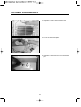
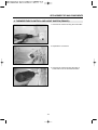
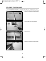
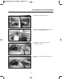
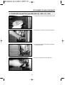
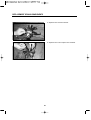
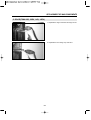
1
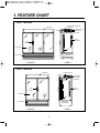
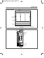
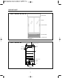
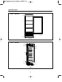
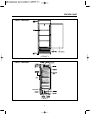
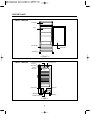
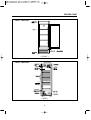
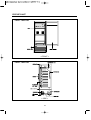
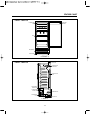
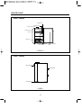
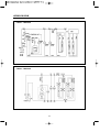
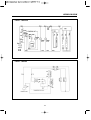
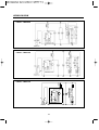
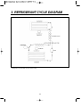
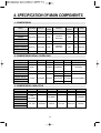
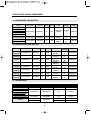
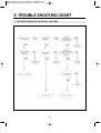
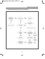
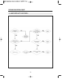
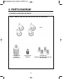
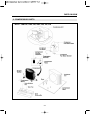
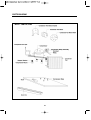
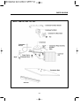
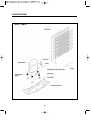
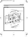
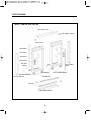
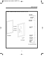
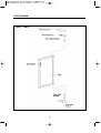
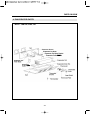
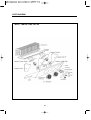
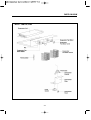
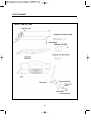
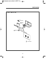
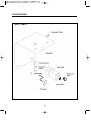
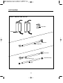
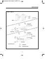
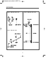
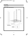
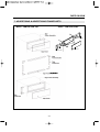
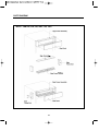
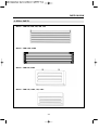
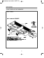
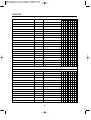
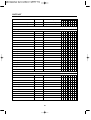
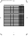
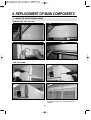
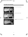
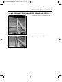
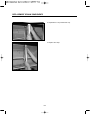
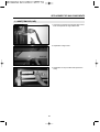
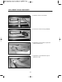
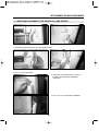
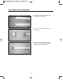
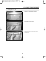
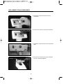
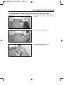
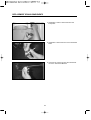
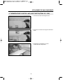
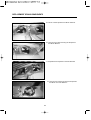
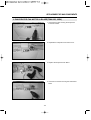
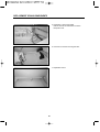
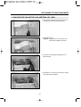
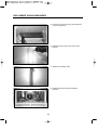
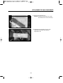
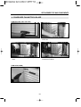
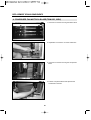
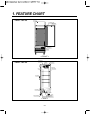
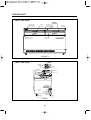
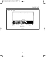
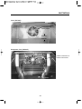
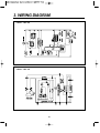
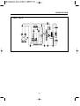
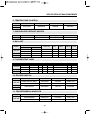
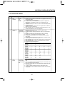
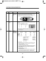
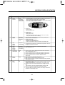
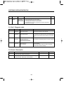
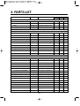
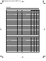
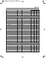
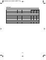
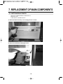
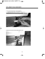
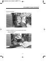
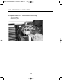
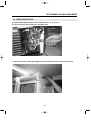
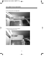
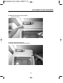
Headquarter: 1250 Victoria street
CARSON, CA 90746
& Canada Toll Free 800-627-0032
TEL: 310-900-1000
FAX: 310-900-1077
www.turboairinc.com
0210001
Commercial
Refrigerator & Freezer
Service Manual
Model No.: TGM-72RS
TGM-69R
TGM-50RS
TGM-48R
TGM-45R
TGM-35R
TGM-33R
TGM-22R
TGM-22RV
TGM-14R
TGM-14RV
TGM-11R
TGM-11RV
TGM-5R
TGF-23F
TGF-13F
TGF-9F
Commercial
Refrigerator
Service Manual
Model No.: TGM-72RS
TGM-69R
TGM-50RS
TGM-48R
TGM-45R
TGM-35R
TGM-33R
TGM-22R
TGM-22RV
TGM-14R
TGM-14RV
TGM-11R
TGM-11RV
TGM-5R
TGF-23F
TGF-13F
TGF-9F
TABLE OF CONTENTS
<REFRIGERATOR>
1. FEATURE CHART ............................................................................................................ 2
2. WIRING DIAGRAM ......................................................................................................... 13
3. REFRIGERANT CYCLE DIAGRAM ............................................................................. 18
4. SPECIFICATION OF MAIN COMPONENTS ............................................................... 19
5. TROUBLE SHOOTING CHART .................................................................................... 22
1. REFRIGERATION SYSTEM ................................................................................................................... 22
2. REFRIGERATION SYSTEM ................................................................................................................... 23
3. LIGHTING SYSTEM ................................................................................................................................. 24
4. NOISE LEVEL .......................................................................................................................................... 25
6. PARTS DIAGRAM .......................................................................................................... 26
1. CASTER PARTS ...................................................................................................................................... 26
2. COMPRESSOR PARTS .......................................................................................................................... 27
3. DOOR PARTS .......................................................................................................................................... 31
4. EVAPORATOR PARTS ........................................................................................................................... 35
5. LIGHTING PARTS .................................................................................................................................... 41
6. SHELF PARTS ......................................................................................................................................... 46
7. ADVERTISING & ADVERTISING FRAME PARTS ............................................................................... 47
8. GRILL PARTS ........................................................................................................................................... 49
9. HOW TO REPLACE THE THERMOSTAT...............................................................................................50
7. PARTS LIST .................................................................................................................... 51
8. REPLACEMENT OF MAIN COMPONENTS ............................................................... 60
1. LAMP ......................................................................................................................................................... 60
2. THERMOSTAT AND LIGHT SWITCH ................................................................................................... 69
3. COOLING FAN MOTOR & BLADE ......................................................................................................... 76
4. CONDENSER FAN MOTOR & BLADE .................................................................................................. 85
5. DOOR ........................................................................................................................................................ 89
<FREEZER>
1. FEATURE CHART........................................................................................................... 91
2. PART DETAILS ............................................................................................................... 92
3. WIRING DIAGRAM ......................................................................................................... 96
4. SPECIFICATION OF MAIN COMPONENTS ............................................................... 98
5. ELECTRONIC CONTROLLER INSTRUCTION ........................................................ 100
6. PART LIST ..................................................................................................................... 105
7. REPLACEMENT OF MAIN COMPONENT ................................................................ 109
7-1. BOTTOM GRILLE PARTS ................................................................................................................. 109
7-2. REPLACING DOOR ........................................................................................................................... 113
1
1. FEATURE CHART
• Model : TGM-72RS
EVAPORATOR FAN MOTOR &
FAN BLADE
SIGN PANEL
EVAPORATOR COIL
EVAPORATOR
DRAIN PAN
LAMP
SHELF
STANDARD
DOOR
HANDLE
GLASS DOOR
LAMP
COMPRESSOR
COMPARTMENT
BOTTOM GRILL
< FRONT >
< SIDE >
• Model : TGM-50RS
EVAPORATOR COIL
SIGN PANEL
EVAPORATOR
DRAIN PAN
EVAPORATOR
FAN MOTOR &
FAN BLADE
SHELF
STANDARD
DOOR
HANDLE
GLASS DOOR
LAMP
BOTTOM GRILL
COMPRESSOR
COMPARTMENT
< FRONT >
< SIDE >
2
FEATURE CHART
SIGN PANEL
• Model : TGM-69R
DOOR HANDLE
GLASS DOOR
BOTTOM GRILL
LEVELING LEG
< FRONT >
EVAPORATOR FAN BLADE
LAMP SWITCH
EVAPORATOR FAN MOTOR
EVAPORATOR COIL
LAMP
KNOB
EVAPORATOR
DRAIN PAN
SHELF
CONDENSER COIL
DRAIN PAN
COMPRESSOR
< SIDE >
3
FEATURE CHART
• Model : TGM-48R, 45R, 35R, 33R
SIGN PANEL
DOOR
DOOR HANDLE
BOTTOM GRILL
LEVELING LEG
< FRONT >
EVAPORATOR COIL
• Model : TGM-48R, 35R
FLUORESCENT
LAMP
EVAPORATOR FAN MOTOR
EVAORATOR
FAN BLADE
THERMOSTAT
FLOURESCENT
LAMP
SHELF
CONDENSER FAN BLADE
CONDENSER
FAN MOTOR
DRAIN PAN
COMPRESSOR
CONDENSER COIL
< SIDE >
4
FEATURE CHART
• Model : TGM-45R, 33R
EVAPORATOR COIL
COMPRESSOR
CONDENSER
COIL
DRAIN PAN
< SIDE >
5
FEATURE CHART
• Model : TGM-22R
SIGN
PANEL
SHELF
BOTTOM GRILL
DOOR GLASS
LEVELING
LEG
< FRONT >
• Model : TGM-22R
EVAPORATOR EVAPORATOR
THERMOSTAT FAN MOTOR FAN BLADE EVAPORATOR COIL
BALLAST
SIGN PANEL
FLUORES
-CENT LAMP
DRAIN ELBOW
DOOR HINGE
TOP
DRAIN HOSE
SUCTION PIPE
-COVER
HANDLE
DOOR HINGE
BOTTOM
COMPRESSOR
CONDENSER
COIL
DRAIN PAN
CONDENSER FAN BLADE
CONDENSER FAN MOTOR
< SIDE >
6
FEATURE CHART
• Model : TGM-22RV
< FRONT >
• Model : TGM-22RV
< SIDE >
7
FEATURE CHART
• Model : TGM-14R
SIGN PANEL
SHELF
BOTTOM GRILL
DOOR GLASS
LEVELING LEG
< FRONT >
• Model : TGM-14R
EVAPORATOR COIL
EVAPORATOR FAN MOTOR
BALLAST
SIGN PANEL
FLUORES
-CENT LAMP
DOOR HANDLE
DRAIN PAN
CONDENSER COIL
CONDENSER FAN MOTOR
COMPRESSOR
< SIDE >
8
FEATURE CHART
• Model : TGM-14RV
< FRONT >
• Model : TGM-14RV
< SIDE >
9
FEATURE CHART
• Model : TGM-11RV
< FRONT >
• Model : TGM-11RV
< SIDE >
10
FEATURE CHART
• Model : TGM-11R
FLUORESCENT
LAMP
SIGN PANEL
STICKER
SHELF
BOTTOM GRILL
LEVELING LEG
< FRONT >
EVAPORAOR
FAN MOTOR
• Model : TGM-11R
EVAPORATOR
FAN BLADE
EVAPORATOR
COIL
CONDENSER
FAN MOTOR
CONDENSER
FAN BLADE
COMPRESSOR
CONDENSER
COIL
DRAIN PAN
< SIDE >
11
FEATURE CHART
• Model : TGM-5R
THERMOSTAT
CONTROL BOX
FLUORE SCENT LAMP
EVAPORATOR
SHELF
DRAIN PAN
GASKET
LAMP SWITCH
DOOR
< FRONT >
• Model : TGM-5R
DOOR HANDLE
CONDENSER
LEVELING LEG
< SIDE >
12
• Model : TGM-48R, TGM-50RS
13
WH
WH
WH
WH
YW YW
YW YW
WH
WH
S/C
WH
WH
WH
YW YW
LAMP
SWITCH
RD
BL RD
BL
WH
CO MP
BK GY
GY
CONDENSING
MOTOR
COOLING
MOTOR (2)
BK
BALLAST
F/L LAMP
F/L LAMP
YW YW
BK
E
POWER
THERMOSTAT
BK
BK
BK
BK
WH
WH
WH
WH
BL
BK
RD
BK
BL RD
COOLING
MOTOR (1)
F/L LAMP
F/L LAMP
BALLAST
LAMP
SWITCH
2. WIRING DIAGRAM
• Model : TGM-69R, TGM-72RS
WIRING DIAGRAM
• Model : TGM-45R
3
4
• Model : TGM-35R
14
WIRING DIAGRAM
• Model : TGM-33R
3
• Model : TGM-5R
15
F/L Lamp(17W)
F/L Lamp(17W)
4
WIRING DIAGRAM
• Model : TGM-22R
• Model : TGM-14R
BK
THERMOSTAT
• Model : TGM-11R
BK
BK
3
4
BK
WH
GY
WH
M
A3
OL
G/S
F/M1
FL
(13W)
F/M2
WH
1
GN
COMPRESSOR & P-RELAY
POWER PLUG
WH
16
WH
BL
BL
BR
BALLAST(13W)
S/V
WH
R/C
PK
BK
2
WH
WH
WH
WIRING DIAGRAM
• Model : TGM-22RV
• Model : TGM-14RV
• Model : TGM-11RV
17
3. REFRIGERANT CYCLE DIAGRAM
• Refrigerant for all models: R-134a (CFC-Free)
18
4. SPECIFICATION OF MAIN COMPONENTS
1. COMPRESSOR
MODEL
HORSE
POWER
CAPACITY
3/4 HP
8,200 BTU/h
CSIR
1,190W TECUMSEH
AKA4476YXA 30200A4700
1/2 HP
7,880 BTU/h
(856 Kcal/h)
CSIR
750W TECUMSEH
AEA4448YXA 30200J2100
1/3 HP
4,650 BTU/h
CSIR
457W TECUMSEH
PART NAME
PART NO.
TGM69R/TGM72RS AKA4482YXA 30200K2900
TYPE OF INPUT
MOTOR
MAKER
TGM48R/TGM50RS
TGM45R
TGM35R
TGM33R
TGM22R / TGM22RV
TGM14R / TGM14RV
HBL27YE-1
3952127G10
1/3 HP
2,080 BTU/h
(226 Kcal/h)
CSR
220W DAEWOO
HFL11Y-1
3953111E10
1/10 HP
874 BTU/h (95Kcal/h)
RSIR
107W DAEWOO
TGM11R / TGM11RV
TGM5R
2. COMPRESSOR RELAY, OVERLOAD
MODEL
PART NAME
PART NO.
MAKER
OVERLOAD
PART NO.
MAKER
TGM69R/TGM72RS 820ARR2B19
TECUMSEH 8300MRAK30
TECUMSEH
TGM48R/TGM50RS
TGM45R
82498-1
TECUMSEH 8300MRAM53
TECUMSEH
TGM35R
TGM33R
820RR12E72
TECUMSEH 8300MRTM75
TECUMSEH
TGM22R / TGM22RV
4TM-783RHB 3817908600
TGM14R / TGM14RV
PTC 068
3017906900 DAEWOO 4TM-783SHB 3817910600 TEXAS INSTRUMENT
TGM11R / TGM11RV
TGM5R
4TM-293THB 3817906500
3. COMPRESSOR CAPACITOR
MODEL
PART NAME
TGM69R/TGM72RS
TGM48R/TGM50RS
125V
TGM45R
378~445MFD
TGM35R
TGM22R / TGM22RV
TGM14R / TGM14RV 220V 100㎌
TGM11R / TGM11RV
PART NO.
MAKER
RUNNING
PART NO.
MAKER
-
-
-
-
-
-
TECUMSEH
-
-
TECUMSEH
401RD35050
DAEWOO
230V 10㎌
400EL15130
DAEWOO
19
SPECIFICATION OF MAIN COMPONENTS
4. CONDENSER FAN MOTOR
BLADE
(NUMBER)
MODEL
PART NAME
PART NO.
POLE
INPUT
TYPE
MAKER
TGM69R/TGM72RS
TGM48R/TGM50RS
TGM45R
TGM35R
TGM33R
IS-4420DWSG-1
3963220410
4P
47W
Shaded Pole
Induction
Aluminum
SUNGSHIN
(5)
TGM22R / TGM22RV
IS-4420DWSR-1
3963229000
4P
47W
TGM14R / TGM14RV
IS-3225DWSQ-2
TGM11R / TGM-11RV
3963326710
2P
36W
Shaded Pole
Induction
Shaded Pole
Induction
Aluminum
SUNGSHIN
(5)
Zytel
SUNGSHIN
(6)
5. EVAPORATOR FAN MOTOR
MODEL
PART NAME
PART NO. POLE
TGM69R
IS-4420DWSN-2A 396328120
TGM72RS
TGM48R
IS-3220DWSF
3963220501
TGM50RS
INPUT
4P
43W
2P
18W
TGM45R
IS-3225DWSL-1
3963329510
2P
18W
TGM35R
IS-3220DWSF
3963220501
2P
18W
TGM33R
IS-3225DWSL-1
3963329510
2P
18W
IS-3210DWSB-2
3963328610
2P
16W
IS-4420DWSN-2
3963328110
4P
43W
IS-3210DWSB-3
3963328620
2P
16W
TGM22R
TGM22RV
TGM14R
TGM14RV
TGM11R
TGM11RV
TYPE
Shaded Pole
Induction
Shaded Pole
Induction
Shaded Pole
Induction
Shaded Pole
Induction
Shaded Pole
Induction
Shaded Pole
Induction
Shaded Pole
Induction
Shaded Pole
Induction
BLADE
(NUMBER)
Aluminum
(5)
Zytel
(3)
Zytel
(6)
Zytel
(3)
Zytel
(6)
ABS
(4)
Aluminum
(5)
ABS
(4)
MAKER
SUNGSHIN
SUNGSHIN
SUNGSHIN
SUNGSHIN
SUNGSHIN
SUNGSHIN
SUNGSHIN
SUNGSHIN
6. THERMOSTAT
MODEL
TGM69R/TGM72RS
TGM48R/TGM50RS
TGM45R
TGM35R
TGM33R
TGM22R / TGM22RV
TGM14R / TGM14RV
TGM11R / TGM11RV
TGM5R
PART NAME
K55-Q5606
K55-Q5605
PART NO.
30283K0110
30283K0100
TYPE
C.C.I
C.C.I
MAKER
RANCO
RANCO
K55-Q5602
30283D0700
C.C.I
RANCO
K61-Q5603
30283D0800
C.C.I
RANCO
PFN-110U-02D
GNF-110U-02D
3018301001
NORMAL
NORMAL
PACIFIC
SHINHAN
20
SPECIFICATION OF MAIN COMPONENTS
7. BALLAST
MODEL
TGM69R/TGM72RS
TGM48R/TGM50RS
TGM45R
TGM35R
TGM33R
TGM22R
TGM22RV
TGM14R
TGM14RV
TGM11R
TGM11RV
TGM5R
PART NAME
ADVANCE
MAGNETEK
R-2P32-TP
M232SR120C
R-2P32-TP
M-232SR120C
R-1P32-TP
M-132R120C
R-2P825-TP
731-L-TC-P
R-1P32-TP
M-132R120C
R-1P825-TP
727-L-TC-P
R-1P32-TP
M-132R120C
R-2P817-TP
701-L-TC-P
R-2P817-TP
701-L-TC-P
R-1P32-TP
M-132R120C
R-1P817TP
703-L-TC-P
DD22B (MAKER : DONGDO)
R-1P825-TP
727-L-TC-P
DD22B (MAKER DONGDO)
DD22B (MAKER : DONGDO)
R-1P825-TP
727-L-TC-P
DD22B (MAKER : DONGDO)
PART NO.
30285D0500
30285D0500
30285A0700
30285J1200
30285A0700
30285J1200
30285A0700
30285H1500
30285H1500
30285A0700
30200H7400
30200A0140
30285J1200
30200A0140
30200A0140
30285J1200
30200A0140
QTY
2
1
1
1
1
1
1
1
1
1
1
2
1
1
1
1
1
WATT
32W
32W
32W
25W
32W
25W
32W
17W
17W
32W
17W
13W
25W
13W
13W
25W
13W
CURRENT
0.61A
0.61A
0.32A
0.30A
0.32A
0.30A
0.32A
0.39A
0.39A
0.32A
0.21A
0.28A
0.30A
0.28A
0.28A
0.30A
0.28A
TYPE
Rapid
Rapid
Rapid
Rapid
Rapid
Rapid
Rapid
Rapid
Rapid
Rapid
Rapid
Preheated
Rapid
Preheated
Preheated
Rapid
Preheated
8. FLUORESCENT LAMP
MODEL
PART NAME
TGM69R/TGM72RS F32T8/TL850
TGM48R/TGM50RS F32T8/TL850
F32T8/TL850
TGM45R
F25T8/TL950
F32T8/TL850
TGM35R
F25T8/TL950
F32T8/TL850
TGM33R
F17T8/TL950
TGM22R
F17T8/TL950
F32T8/TL850
TGM22RV F17T8/TL950
TGM14R
F13T8/CW
F28T8/TL950
TGM14RV
F13T8/CW
TGM11R
F13T8/CW
TGM11RV F28T8/TL950
TGM5R
F13T8/CW
PART NO.
30200D2800
30200D2800
30200D2800
30236A0500
30200D2800
30236A0500
30200D2800
30236H0500
30236H0500
30200D2800
30236H0500
30236F0500
30236A0500
30236F0500
30236F0500
30236A0500
30236F0500
QTY WATT LENGTH
4
32W
48”
2
32W
48”
1
32W
48”
2
25W
36”
1
32W
48”
1
25W
36”
1
32W
48”
2
25W
36”
2
17W
24”
1
32W
48”
1
17W
24”
2
13W
12”
1
25W
36”
1
13W
12”
1
13W
12”
1
25W
36”
1
13W
12”
DESCRIPTION
TL80, 5000K
TL80, 5000K
TL80, 5000K
TL80, 5000K
TL80, 5000K
TL80, 5000K
TL80, 5000K
TL80, 5000K
TL80, 5000K
TL80, 5000K
TL80, 5000K
COOL WHITE, 4100K
TL80, 5000K
COOL WHITH, 4100K
COOL WHITE, 4100K
TL80, 5000K
COOL WHITE, 4100K
BULB
T8
T8
T8
T8
T8
T8
T8
T8
T8
T8
T8
T8
T8
T8
T8
T8
T8
MAKER
PHILIPS
or
GE
9. LIGHT STATER
MODEL
TGM14R / TGM14RV
TGM11R
TGM5R
PART NAME
PART NO.
BASE
MAKER
FS-2
30236A0700
P21
OPO
10. LAMP SWITCH
MODEL
ALL
TYPE
ROCKER SWITCH
PART NO.
30281A0600
21
RATING
125V, 6A
MAKER
DAESUNG
5. TROUBLE SHOOTING CHART
1. THE REFRIGERATOR DOES NOT COOLING
22
TROUBLE SHOOTING CHART
2. THE REFRIGERATOR DOES NOT COOLING WELL
23
TROUBLE SHOOTING CHART
3. LAMP DOES NOT LIGHT WELL
24
TROUBLE SHOOTING CHART
4. WHEN THERE IS AN EXCESSIVE NOISE
25
6. PARTS DIAGRAM
1. CASTER or LEVELING LEG PARTS
•Model : TGM-69R, 72RS, 48R, 50RS, 45R, 35R, 33R, 22R, 14R, 14RV (Option)
Caster
LEVELING LEG
(TGM-14R,
14RV,11R, 11RV)
LEVELING LEG
(TGM-5R)
26
LEVELING LEG
(TGM-69R, 72RS, 48R, 50RS, 45R, 35R,
33R, 22R, 22RV)
PARTS DIAGRAM
2. COMPRESSOR PARTS
•Model : TGM-69R, 72RS, 48R, 50RS, 45R, 35R, 33R
27
PARTS DIAGRAM
•Model : TGM-22R, 22RV
28
PARTS DIAGRAM
•Model : TGM-14R, 14RV, 11R, 11RV
29
PARTS DIAGRAM
•Model : TGM-5R
30
PARTS DIAGRAM
3. DOOR PARTS
•Model : TGM-69R
Door Channel Top
Door Stopper Cushion
Rope
r
Rolle
Door Gasket
(Door *M)
Door Frame
Door Glass
Door Handle
ht
Weig
Door Channel Right
Door Assembly*LEFT
Door Assembly*MIDDLE
Door Channel Left
Door Roller
Door Assembly*RIGHT
Door Roller
Door Channel Bottom
31
PARTS DIAGRAM
•Model : TGM-48R, 45R, 35R, 33R
Door Channel Top
Door Stopper Cushion
Door Seal Top
Door Gasket
Door Frame
Door Glass
Door Handle
Door Seal
Bottom
Door Chabbel
Right
Door Roller(A)
Door Assembly*LEFT
Door Channel Left
Door Roller(C)
Door Rail
Door Channel Bottom
32
Door Assembly*RIGHT
PARTS DIAGRAM
•Model : TGM-72RS, 50RS, 22R, 22RV, 14R, 14RV, 11R, 11RV
33
PARTS DIAGRAM
•Model : TGM-5R
34
PARTS DIAGRAM
4. EVAPORATOR PARTS
•Model : TGM-48R, 50RS, 35R
35
PARTS DIAGRAM
•Model : TGM-69R, 72RS, 45R, 33R
36
PARTS DIAGRAM
•Model : TGM-22R, 22RV
37
PARTS DIAGRAM
•Model : TGM-14R, 14RV
38
PARTS DIAGRAM
•Model : TGM-11R. 11RV
Thermostat
Thermostat
Bracket
Evaporator
Fan Motor
Evaporator
Fan Blade
Thermostat
Knob
Thermometer
39
PARTS DIAGRAM
•Model : TGM-5R
40
PARTS DIAGRAM
5. LIGHTING PARTS
•Model : TGM-48R, 50RS, 35R, 22R
41
PARTS DIAGRAM
•Model : TGM-69R, 72RS, 45R, 33R
Lamp Switch
Ballast
Lamp Socket
Lamp (for Sign Panel)
Lamp Socket
Lamp (for Cabinet Liner)
Lampshield
42
Lampshield End Cap
PARTS DIAGRAM
•Model : TGM-14R
43
PARTS DIAGRAM
•Model : TGM-22RV, 14RV, 11RV
•Model : TGM-22RV, 14RV, 11RV
•Model : TGM-22RV, 14RV
44
PARTS DIAGRAM
•Model : TGM-11R, 5R
45
PARTS DIAGRAM
6. SHELF PARTS
•Model : TGM-69R, 72RS, 48R, 50RS, 35R
46
PARTS DIAGRAM
7. ADVERTISING & ADVERTISING FRAME PARTS
•Model : TGM-69R, 48R, 35R
•Model : TGM-72RS, 50RS
Sign Frame *Right
Rubber Cap
Screw
Sign Panel
Sign Frame *Left
47
PARTS DIAGRAM
•Model : TGM-45R, 33R, 22R, 22RV, 14R, 14RV
48
PARTS DIAGRAM
8. GRILL PARTS
•Model : TGM-69R, 48R, 45R, 35R, 33R
•Model : TGM-72RS, 50RS
•Model : TGM-22R, 22RV
•Model : TGM-14R, 14RV, 11R, 11RV
49
PARTS DIAGRAM
9. HOW TO REPLACE THE THERMOSTAT
•Model : TGM-69R
50
7. PARTS LIST
Part Name
Part Number
Description
Model
69 48 45 35 33 22 14 11 5
Caster & Leveling Legs
Castor
30265L0100
1/2” Stem(TP5040-22-HDP-TLE) 2 2 2 2 2 2 2
Caster
30265L0200
1/2” Stem(TP5040-22-HDP)
2 2 2 2 2 2 2
Leveling Leg
30260K0100
1/2”
4 4 4 4 4 4
Leveling Leg
3012101300
BLACK
Leveling Leg
4006D32533
BLACK
Compressor
30200K2900
AKA4482YXA(TECUMSEH)
Compressor
30200J2100
AEA4448YXA(TECUMSEH)
Compressor
30200A4700
AKA4476YXA(TECUMSEH)
Compressor
3952127G10
HBL27YE-1(DAEWOO)
Compressor
3953111E10
HFL11Y-1(DAEWOO)
Compressor Relay
3817906900
PTC068
1 1 1 1
Compressor Relay Assembly
30227H0911
Including Harness
1
Compressor Relay Assembly
30227F0911
Including Harness
Compressor Relay Assembly
30200A6411
Including Harness
Compressor Overload
3817908600
4TM-783RHB(TEXAS INS.)
Compressor Overload
3817910600
4TM-783SHB(TEXAS INS.)
Compressor Overload
3817906500
4TM-293THB(TEXAS INS.)
Compressor Running Capactor
400EL15130
230V 10uF
1 1 1
Compressor Running Capactor
401RD35050
220V 100uF
1 1 1
Condenser
30200K3001
Refer Parts Diagram
Condenser
30200A2201
Refer Parts Diagram
Condenser
30200H1000
Refer Parts Diagram
Condenser
30200F0816
Refer Parts Diagram
Condenser
30200F1110
Refer Parts Diagram
Condenser
30200A7204
Refer Parts Diagram
2 2
2
Compressors
Condenser Fan Motor
3963220410
IS-4420DWSG-1
Condenser Fan Motor
3963320410
IS-4420DWSR-1
Condenser Fan Motor
3963226710
IS-3225DWSQ-2
Condenser Fan Motor Blade
30218A0100
AL ø 250
Condenser Fan Motor Blade
30218B0100
AL ø 225
Condenser Fan Motor Blade
30218F0100
Zytel ø 150
51
1
1
1 1 1
1 1 1
1
1 1
1
1
1 1
1
1
1 1 1 1
1
1
1
1
1 1 1 1 1
1
1 1
1 1 1 1 1
1
1 1
PARTS LIST
Part Name
Part Number
Description
Model
69 48 45 35 33 22 14 11 5
1 1 1 1
Dryer
30268A0100
30g Refer Parts Diagram
Dryer
30268H0100
30g Refer Parts Diagram
Dryer
30268F0403
30g Refer Parts Diagram
Dryer
30268K0100
30g Refer Parts Diagram
Dryer
3016801300
10g Refer Parts Diagram
Dryer
30268Q0300
C-052-S
1 1
Power Cord
30213A1000
KKP-30B
1 1 1 1 1 1 1 1 1
Power Cord Clamp
30212A0600
SPG
1 1 1 1 1 1 1 1 1
Drain Wicking Pad
30245A0700
1
1 1
1
1
1
1 1 1 1 1
Drain Pan
30211J0100
HIPS
Drain Pan
3021100001
HIPS
Drain Wicking Bar
30230J0700
PVC-H
1 1 1 1 1
Brush Seal
30277A1301
Bottom
1 1 1 1
Door Hinge Cap
4009G51041
PE Plastic White
Door Assembly *R
30217D0105
Glass, Slide, Right
1
Door Assembly *L
30217D0206
Glass, Slide, Left
1
Door Assembly *L
30200J2500
Glass, Slide, Left
1 1 1 1 1
1 1 1
Doors
1
1
Door Assembly *L
30220J2800
Glass, Slide, Left
Door Assembly *R
30200J2400
Glass, Slide, Right
Door Assembly *R
30217A0311
Glass, Slide, Right
Door Assembly *R
30200J2900
Glass, Slide, Right
Door Assembly *L
30217A0301
Glass, Slide, Left
Door Assembly *L
30217K0100
Glass, Slide, Left
1
Door Assembly *M
30217K0300
Glass, Slide, Middle
1
Door Assembly *R
30217K0200
Glass, Slide, Right
1
Door Assembly
30217H0101
Glass, Swing
Door Assembly
30217F0501
Glass, Swing
Door Assembly
30200A8020
Glass, Swing
Door Assembly
30217G0301
Glass, Swing
Door Gasket
30222A1001
Wiper Style
Door Gasket
30223H0200
Magnetic
Door Gasket
30223F0200
Magnetic
Door Gasket
30223A9006
Magnetic
Door Gasket
30223F0100
Magnetic
52
1
1
1
1
1
1
1
1
1
1
1
1
1
1
1
PARTS LIST
Door Glass
30255K0100
T24
Model
69 48 45 35 33 22 14 11 5
1
Door Glass
30255J1100
T24
1
Door Glass
30255J0200
T24
Door Glass
30255D0110
T24
Door Glass
30255A0110
T24
Door Glass
30255H1100
T24
Door Glass
30255F1100
T24
Door Glass
30255A9010
T24
Door Glass
30255G1100
T24
Part Name
Part Number
Description
1
1
1
1
1
1
1
Door Handle
30226A0101
Slide ABS Plastic Black
Door Handle
30226G0101
Swing Aluminum
Door Handle
3022600300
Swing Aluminum
Door Hinge Bracket Top
30229H3000
Top
Door Hinge Bracket Top
4004D51301
Top
Door Hinge Bracket Bottom
30229H2100
Bottom
Door Hinge Bracket Bottom
30200B8703
Bottom
Door Hinge Bushing
3020700000
Nylon Top
1 1 1
Door Hinge Bushing
30207H1000
Nylon Bottom
1 1 1
Door Hinge Bushing
4005B45213
Nylon Top, Bottom
Door Hinge Spring
30251H0101
Torsion Style
Door Hinge Spring
30251G0100
Torsion Style
Door Hinge Spring
30252H1100
StainlessT1.5 Bottom
Door Channel Top
30287D0103
PVC-H, Top
Door Channel Top
30287J1100
PVC-H, Top
Door Channel Top
30287A0306
PVC-H, Top
Door Channel Top
30287J1200
PVC-H, Top
Door Channel Bottom
30287D0203
PVC-H, Bottom
Door Channel Bottom
30287J1500
PVC-H, Bottom
Door Channel Bottom
30287A0406
PVC-H, Bottom
1 1 1 1 1
1 1 1
1
1 1 1
1
1 1 1
1
1
1
1 1
1 1 1
1
1
1
1
1
1
1
Door Channel Bottom
30287J1600
PVC-H, Bottom
Door Channel Left
30287J0500
PVC-H, Left
Door Channel Left
30287A0603
PVC-H, Left
Door Channel Right
30287J0600
PVC-H, Right
Door Channel Right
30287A0703
PVC-H, Right
Door Channel Top
30287K0301
PVC-H, Top
1
Door Channel Bottom
30287K0401
PVC-H, Under
1
53
1
1
1
1
1
1
1
1
1
PARTS LIST
Door Channel Left
30287K0500
PVC-H, Left
Model
69 48 45 35 33 22 14 11 5
1
Door Channel Right
30287K0600
PVC-H, Right
1
Door Rail
30287D0300
Stainless
Door Rail
30287A0500
Stainless
Door Rail
30287J2200
Stainless
Door Rail
30287J2100
Stainless
Door Rail (A)
30287K0100
SUS304
1
Door Rail (B)
30287K0200
SUS304
1
Door Roller
30247A0500
Part Name
Part Number
Description
1
1
1
1
1
Door Roller
30206A1400
Door Roller
30206D0300
Door Roller
30247K0200
Tok DU-22-H
Door Sealer Top
30277D0241
Top
Door Sealer Top
30277J0800
Top
Door Sealer Top
30277A0231
Top
Door Sealer Top
30277J0900
Top
Door Stopper
30252H1000
StainlessT3.0 Bottom
Door Stopper
30252F0100
SUS304 T2.0 Bottom
Door Stopper Cushion
30252K0200
Rubber Blocks
Door Stopper Cushion
30252A0200
Rubber Blocks
Control Box
30205A9000
HIPS
Evaporator Drain Pan
30211A0101
HIPS
Evaporator Drain Pan
30211F0101
HIPS
Evaporator Drain Pan
4017J54111
HIPS
Evaporator Drain Pan
30211Q0100
AL
Evaporator Coil
30200J6200
FIN TUBE (AL+Cu)
Evaporator Coil
30270Q0110
FIN TUBE (AL+Cu)
1
1
1
1
1
1
1
1
1
1
1
1 1
1
1
1
Evaportaors
Evaporator Coil
30270A1100
FIN TUBE(AL+Cu)
Evaporator Coil
30270H0100
FIN TUBE(AL)
Evaporator Coil
30270F0104
FIN TUBE(AL+Cu)
Evaporator Coil
30200A8101
ROLL BOND(AL)
Evaporator Coil
30270G0100
AL
Evaporator Fan Motor
3963329510
IS-3225 DWSL-1-C
Evaporator Fan Motor
3963220501
IS-3220DWSF
54
1
1
1
1
1
1
1
1
1
1
1
1
1
1
1
2
2
2
2
PARTS LIST
Part Name
Part Number
Description
Model
69 48 45 35 33 22 14 11 5
2
Evaporator Fan Motor
3963328610
IS-3210DWSB-2
Evaporator Fan Motor
3963328110
IS-4420DWSN-2
Evaporator Fan Motor
3963328120
IS-4420DWSN-2A
Evaporator Fan Motor
3963328620
IS-3210DWSB-3
Evaporator Fan Motor Blade
30218F0100
Zytel ф 150
Evaporator Fan Motor Blade
4034L38038
Zytel ф 158
Evaporator Fan Motor Blade
3011800400
ABS ф 110
Evaporator Fan Motor Blade
30218F0200
AL ф 175
Evaporator Fixture
30220A9000
PA-6
Evaporator Fan Motor Guard
30214H0102
ABS
Evaporator Fan Motor Guard
30214K0100
HIPS
1
Lamp Switch
30281A0600
125V/6A
1 1 1 1 1 1 1 1 1
Thermometer
30283G0410
MILJOCO
1 1 1 1 1 1 1 1 1
Thermostat
30283K0100
K55-Q5605(Ranco)
Thermostat
30283K0110
K55-Q5606(Ranco)
Thermostat
30283D0700
K55-Q5602(Ranco)
Thermostat
30283D0800
K61-Q5603(Ranco)
Thermostat
3018301001
PFN-110U-02D, GNF-110U-02D
Thermostat Bracket
30220A1410
SPG, Refer Parts Diagram
Thermostat Bracket
30206F1000
SPG, Refer Parts Diagram
Thermostat Bracket
30220J1000
SPG, Refer Parts Diagram
Thermostat Knob
30234A1000
HIPS
Thermostat Knob
4006D70026
HIPS OFF1234567
Thermostat Plate
30242J0100
EGI+Painting
Thermostat Plate
30206A0200
EGI+Painting
Thermostat Plate
30206H0104
EGI+Painting
Thermostat Plate
30242F0802
HIPS
Thermostat Plate
30245K0100
EGI 0.6
Bottom Grill Assembly
30200D5500
Ass’y Front Painted
Bottom Grill Assembly
30200A5500
Ass’y Front Painted
Bottom Grill Assembly
30224H0100
Front ABS Dark Gray
Bottom Grill Assembly
30200J2300
Ass’y Front Painted
Bottom Grill Assembly
30200J4300
Ass’y Front Painted
1
2
1
2
2
2
2
1
2
1
1
1
1
1
1 1 1 1
1 1
1
1
1
1
1 1 1 1
1 1 1 1 1 1 1 1
1
1
1
1
1
1
1
1
Grills
55
1
1
1
1
1
1
PARTS LIST
Part Number
Description
Bottom Grill Assembly
30224F0102
Front ABS Dark Gray
Model
69 48 45 35 33 22 14 11 5
1 1
Bottom Grill Assembly
30224K0100
Ass’y Grill
1
Ballast
30285D0500
32Watt x 1 R-2P32-TP
2 1
Ballast
30285A0700
32Watt x 1 R-1P32-TP
1 1 1
Ballast
30200A0110
25Watt x 1 R-1P825-TP
1
Ballast
30285J1200
25Watt x 2 R-2P825-TP
Ballast
30285H1500
17Watt x 2 R-2P817-TP
Part Name
Lightings
Ballast
30200A0140
13Watt x 1 DD22B
Lamp
30200D2800
32Watt F32T8/TL85048”
Lamp
30236A0500
25Watt F25T8/TL95036”
Lamp
30236H0500
17Watt F17T8/TL95024”
Lamp
30236F0500
13Watt F13T8/CW12”
Lamp Shield
30214F0701
ACRYL
Lamp Shield
30214A0010
ACRYL
Lamp Holder
3183005000
SK-5OD28
Lamp Shield
3021101101
PC, t0.5
Lamp Shield
30211H0000
PC, t0.5
1
1 1
1
4 2 1 1 1
1 1
1 2
2 1 1
1
1
2
2
2 2
2 1 1 1
1
Lamp Shield
30211F0000
PC, t0.5
Light Starter
30236A0700
FS-2
Lamp Switch
30281A0600
125V/6A
Shelf
30278D0107
Wire, White
Shelf
30278A0207
Wire, White
Shelf
30278K0100
Wire, White
Shelf
30278H0103
Wire, White
Shelf(A)
30278F0111
Wire, White TOP
3
Shelf(B)
30278F0211
Wire, White BOTTOM
1
Shelf(T)
30278A9401
Wire, White TOP
Shelf *L
30278J0100
Wire, White
Shelf *L
30278J0300
Wire, White
Shelf *R
30278J0200
Wire, White
Shelf *R
30278J0400
Wire, White
1
1
1 1 1 1 1 1 1 1 1
Shelves
56
6
6
9
4
1
3
3
3
3
PARTS LIST
Part Name
Part Number
Description
Model
69 48 45 35 33 22 14 11 5
1
Shelf(M)
30278A9150
Wire, White MIDDLE
Shelf(B)
30278A9000
Wire, White BOTTOM
Shelf(A)
30278G0111
Wire, White TOM
3
Shelf(B)
30278G0401
Wire, White BOTTOM
1
Shelf Bracket
30220A0200
Front Center White
2 1
1
Shelf Clip(E)
30220A0700
PP TOP
36 24
24
Shelf Clip(D)
30220A0600
Nylon BOTTOM
36 24
24
Shelf Standard
3022000703
Sides & Back of Cabinet White
4 4
4
Shelf Support
30253A0500
Back Center White
2 1
1
Sign Frame *T*B
30222K0900
PVC-H
1
Sign Frame *T*B
30222D0500
PVC-H
Sign Frame *T*B
30222A0800
PVC-H
Sign Frame End
30222A0900
PVC-H
Sign Frame *T*B
30222H0310
PVC-H
Sign Frame *T*B
30222F1902
PVC-H
Sign Frame End
30222F2103
ABS Dark Gray
Sign Frame End *L
30222J0100
PVC-H
1
1
1
1
1
Sign Frame
Sign Frame End *R
30222J0200
PVC-H
Sign Frame Bracket
30220A0900
Aluminum
Sign Panel
30214D0710
PC, t1.5
Sign Panel
30214A1211
PC, t1.5
Sign Panel
30214H0110
PC, t3.0
Sign Panel
30214F0110
PC, t3.0
Sign Panel
30214J4500
PC, t1.5
Sign Panel
30214J4600
PC, t1.5
Sign Panel
30214K1400
PC, t1.5
57
1
1
1 1
1
1
1
1 1
1 1
1
1
1
1
1
1
1
1
PARTS LIST
Part Name
Model
11RV 14RV 14CRV 22RV 22CRV
Part Number
Description
Ballast
30200F7300
25Watt x R-1P825TP
Ballast
30200G7300
25Watt x R-1P825TP
Ballast
30200A0141
13Watt x 1DD22B
Ballast
30200H7400
17Watt x R-1P817-TP
1
1
Ballast
30200H7300
32Watt x R-1P32-TP
1
1
Lamp
30236A0500
25Watt F25T8/TL95036”
Lamp
30236F0500
13Watt F13T8’ CW12”
Lamp
30236H0500
17Watt F17T8/TL95024”
1
1
Lamp
30200D0500
32Watt F32TB/TL85048”
1
1
Lamp Shield
30211K0200
PC, T0.5
1
1
Lamp Shield
30211F0400
PC, T0.5
1
Shelf(A)
30278G0700
Wire, White, Top
3
Shelf(B)
30278G0401
Wire, White, Bottom
1
Shelf(A)
30278F0300
Shelf(B)
Shelf
4
4
Lightings
1
1
1
1
1
1
1
1
1
1
1
1
Wire, White, Top
3
3
30278F0211
Wire, White, Bottom
1
1
30278H0400
Wire, White
Shelves
** Other parts are the same parts as TGM-11R, TGM-14R, TGM-22R
58
PARTS LIST
Part Name
Part Number
Description
Model
50RS
72RS
COMPRESSOR COMPARTMENT
GRILLE ASSEMBLY
30200S2300
ABS + PAINTED STEEL
1
GRILLE ASSEMBLY
30200S3300
ABS + PAINTED STEEL
GRILLE CAP
30209S0200
SILICONE, ø14
4
4
30283D0700
K55-Q5602 (16A)
1
1
DOOR ASSEMBLY *LEFT
30200S2500
FRMAE + GLASS + HANDLE
1
DOOR ASSEMBLY *RIGHT
30200S2400
FRMAE + GLASS + HANDLE
1
DOOR ASSEMBLY *LEFT
30200S3600
FRMAE + GLASS + HANDLE
1
DOOR ASSEMBLY *RIGHT
30200S3500
FRMAE + GLASS + HANDLE
2
DOOR GLASS
30255S0100
1319*636.5*24
DOOR GLASS
30255S0200
1319*586*24
DOOR HANDLE
30226G0101
ZN DIE CASTING, CR COATING
2
3
DOOR HINGE SPRING
30251H0100
TORSION STYLE
2
3
DOOR HINGE BUSHING *TOP
3020700000
NYLON
2
3
DOOR HINGE BUSHING *BOTTOM
30207H1000
NYLON
2
3
DOOR HINGE *TOP *LEFT
30229A0100
T=3.0mm
1
1
DOOR HINGE *TOP *RIGHT
30229A0200
T=3.0mm
1
2
DOOR HINGE *BOTTOM *LEFT
30229H2200
T=5.0mm
1
1
DOOR HINGE *BOTTOM *RIGHT
30229H2103
T=5.0mm
1
2
DOOR GASKET
30223S0200
PVC-S, 660*1336
2
DOOR GASKET
30223S0300
PVC-S, 610*1336
MULLION
30253D0200
PAINTED STEEL, U-TYPE SHAPED
MULLION
30253D0210
PAINTED STEEL, U-TYPE SHAPED
MULLION COVER(A)
30253S0200
PVC-H
1
2
MULLION COVER(B)
30214S0700
PAINTED STEEL, GASKET CONTACTED
1
2
MULLION LAMP SOCKET *TOP & *BOTTOM
30200S1000
JS-212, JS-213
1
2
SIGN FRAME *LEFT
30222A2501
ABS
1
1
SIGN FRAME *RIGHT
30222A2400
ABS
1
1
SIGN PANEL
30242S0600
PC
1
SIGN PANEL
30242S0610
PC
SIGN FRAME CAP
30209S0300
SILICONE, ø15
1
REFRIGERATION COMPARTMENT
TEMPERATURE CONTROL(THERMOSTAT)
DOORS
2
3
3
1
2
SIGN FRAME
** Other parts of TGM-72RS are the same parts as TGM-69R.
** Other parts of TGM-50RS are the same parts as TGM-48R.
59
1
2
2
8. REPLACEMENT OF MAIN COMPONENTS
1. LAMP FOR ADVERTISING PANEL
(TGM-69R, 48R, 45R, 35R, 33R)
1. Separate the Sign Frame End.
2. Separate the Sign Panel.
3. Separate the Lamp Socket.
4. Separate the Lamp out of the Lamp Holder and replace it.
(TGM-72RS, 50RS)
1. Unscrew the left sign frame.
2. Unscrew the right sign frame.
3. Pull the sign panel carefully.
4. Separate the lamp socket.
Separate the lamp out of the lamp holder and
replace it.
60
REPLACEMENT OF MAIN COMPONENTS
5. Take out the Clamp securing wires.
6. Separate the Ballast Connectors.
7. Unscrew two screws securing the Ballast and
replace it.
61
REPLACEMENT OF MAIN COMPONENTS
1. LAMP FOR CABINET LINER(TGM-69R, 72RS, 48R, 50RS, 45R, 35R, 33R)
1. Take out the Doors and separate the Lamp
from the Lamp Holder.
2. Separate the Lamp Socket.
62
REPLACEMENT OF MAIN COMPONENTS
3. Separate the Lamp Shield End Cap.
4. Replace the Lamp.
63
REPLACEMENT OF MAIN COMPONENTS
1. LAMP(TGM-22R,14R)
1. Unscrew four screws securing the Sign Frame
End and separate the Sign Frame End.
2. Separate the Sign Panel.
3. Separate the Lamp Sockets and replace the
Lamp.
64
REPLACEMENT OF MAIN COMPONENTS
4. Separate connector of the ballast.
5. Unscrew two screws securing the Ballast.
6. Separate the Lamp Sockets to replace the
Lamp for Cabinet Liner.
7. Separate the Lamp Shield End Cap and
replace the Lamp.
65
REPLACEMENT OF MAIN COMPONENTS
1. LAMP BASE ASSEMBLY FOR VERTICAL LAMP SERIES
TGM-11RV
TGM-14RV, TGM-22RV
1. UNSCREW THE SCREWS OF THE HOUSING COVER
TGM-11RV
TGM-14RV, TGM-22RV
2. PULL OUT THE HOUSING
3. UNSCREW THE SPECIAL BOLT THAT IS
FIXING THE LAMP BASE ASSEMBLY
(3POINTS)
4. PULL OUT THE LAMP BASE ASSEMBLY
66
REPLACEMENT OF MAIN COMPONENTS
5. SEPARATE THE FLUORESCENT LAMP
FROM THE LAMP HOLDER
6. PULL OUT THE LAMP CAP FROM THE
LAMP CASE
7. REPLACE THE FLUORESCENT LAMP
AFTER PULL OUT THE FLUORESCENT
LAMP FROM THE LAMP CASE.
67
REPLACEMENT OF MAIN COMPONENTS
1. LAMP(TGM-11R,5R)
1. Unscrew two screws securing the Lamp
Shield.
2. Disassemble the Lamp Shield.
3. Separate the Lamp out of the Lamp Holder
and replace it.
68
REPLACEMENT OF MAIN COMPONENTS
2. THEMPERATURE CONTROL AND LIGHT SWITCH(TGM-69R, 72RS, 48R, 50RS, 45R, 35R, 33R)
1. Unscrew four screws securing the Thermostat
control plate.
2. Pull out the Thermostat control plate.
3. Separate the Receptacles out of the
Thermostat and Lamp Switch.
4. Separate the Tube of Thermostat from the
Evaporator.
69
REPLACEMENT OF MAIN COMPONENTS
5. Separate the Thermostat Knob out of the
Thermostat.
6. Unscrew two screws securing the Thermostat.
7. Separate the Thermostat out of the Thermostat
plate.
8. Unscrew two screws securing the Thermostat
out of the Thermostat Bracket.
70
REPLACEMENT OF MAIN COMPONENTS
2. THERMOSTAT CONTROL AND LIGHT SWITCH (TGM-14R, 14RV)
1. Unscrew two screws securing the Thermostat
Plate.
2. Pull out the Thermostat Plate.
3. Separate the Receptacles out of the
Thermostat and Light Switch.
71
REPLACEMENT OF MAIN COMPONENTS
4. Separate the Tube of Thermostat from the
Evaporator.
5. Separate the Thermostat out of the Thermostat
Plate.
6. Unscrew two screws securing the Thermostat
out of the Thermostat Bracket.
72
REPLACEMENT OF MAIN COMPONENTS
2. THEMPERATURE CONTROL AND LIGHT SWITCH(TGM-11R, 11RV)
1. Unscrew six screws securing the Duct.
2. Unscrew four screws securing the Thermostat
Plate.
3. Separate the Receptacles out of the
Thermostat and Lamp Switch.
73
REPLACEMENT OF MAIN COMPONENTS
4. Separate the Tube of Thermostat from the
Evaporator Coil.
5. Pull out the Thermostat plate.
6. Separate the Thermostat out of the Thermostat
plate.
74
REPLACEMENT OF MAIN COMPONENTS
2. THEMPERTURE CONTROL AND LIGHT SWITCH(TGM-5R)
1. Unscrew two screws securing the Control Box.
2. Separate the Connectors.
3. Unscrew two screws securing the Tube of
Thermostat out of the Thermostat Fixture.
75
REPLACEMENT OF MAIN COMPONENTS
3. EVAPORATOR FAN MOTOR & BLADE(TGM-69R, 72RS, 48R, 50RS, 45R, 35R, 33R)
1. Unscrew four screws securing the Thermostat
Plate.
2. Unscrew eight screws securing the Duct.
3. Separate the Duct.
4. Unscrew four screws securing the Evaporator
Drain Pan.
76
REPLACEMENT OF MAIN COMPONENTS
5. Separate the Evaporator Drain Pan.
6. Unscrew four screws securing the Evaporator
Guide *L, *R and separate them.
7. Separate the Vinyl Cover securing the
Evaporator Fan Motor.
8. Separate the Connectors of Evaporator Fan
Motor.
77
REPLACEMENT OF MAIN COMPONENTS
9. Pull out of the Evaporator Fan Motor Harness.
10. Unscrew two screws securing the Evaporator
Fan Motor Bracket.
11. Separate the Evaporator Fan Motor Bracket.
12. Unscrew four screws securing the Evaporator
Fan Motor out of the Bracket.
78
REPLACEMENT OF MAIN COMPONENTS
3. EVAPORATOR FAN MOTOR & BLADE(TGM-22R, 22RV)
1. Unscrew the screw securing the Evaporator
Fan Motor Guard.
2. Separate the Evaporator Fan Motor Cover.
3. Replace the Evaporator Fan Motor.
4. Unscrew four screws securing the Thermostat
Plate.
79
REPLACEMENT OF MAIN COMPONENTS
5. Separate the Thermostat Plate.
Pull out the tube of Thermostat out of the
Evaporator Coil.
6. Unscrew four screws securing the Duct.
7. Separate the Duct.
80
REPLACEMENT OF MAIN COMPONENTS
3. EVAPORATOR FAN MOTOR & BLADE(TGM-14R, 14RV)
1. Unscrew the screws securing the Thermostat
Plate and two screws securing the Duct.
2. Separate the Duct.
(Caution: Pulling the Duct in to the front can
cause the Fan Blade to be bent.)
3. Unscrew four securing the Evaporator Fan
Motor Bracket.
4. Separate the Connectors of Fan Motor, the Nut
and replace the Fan Blade.
81
REPLACEMENT OF MAIN COMPONENTS
5. Unscrew two screws securing the Evaporator
in case of replacing it.
6. Separate Suction Pipe Cover on the Rear
Cabinet.
7. Separate the Sealing Tube.
8. Replace the Suction Pipe with welding
machine.
82
REPLACEMENT OF MAIN COMPONENTS
9. Pull out the Evaporator Coil.
(Caution: Pulling the Evaporator can cause
the Cabinet Liner to be scratched.)
10. Separate the Evaporator Coil out of the
Evaporator Drain Pan and repair the
Evaporator Coil.
83
REPLACEMENT OF MAIN COMPONENTS
3. EVAPORATOR FAN MOTOR & BLADE(TGM-11R, 11RV)
1. Unscrew the screws securing the Duct.
2. Unscrew the screws securing the Thermostat
Plate.
3. Separate the harness out of the Thermostat
and Lamp Switch.
4. Separate the Evaporator Fan Motor Bracket.
84
REPLACEMENT OF MAIN COMPONENTS
4. CONDENSER FAN MOTOR & BLADE
(TGM-69R, 48R, 45R, 35R, 33R)
1. Unscrew four screws securing the Bottom Grill.
2. Separate the Compressor Harness out of the
Switch Box.
3. Unscrew four screws securing the Compressor
Base.
4. Pull the Compressor Base and separate the
Condenser Fan Motor.
(TGM-72RS, 50RS)
85
REPLACEMENT OF MAIN COMPONENTS
4. CONDENSER FAN MOTOR & BLADE(TGM-22R, 22RV)
1. Unscrew four screws securing the Bottom Grill.
2. Separate the Connector out of the Switch Box.
3. Unscrew four screws securing the Compressor
Base.
4. Pull the Compressor Base and separate the
Condenser Fan Motor.
86
REPLACEMENT OF MAIN COMPONENTS
4. CONDENSER FAN MOTOR & BLADE(TGM-14R, 14RV, 11R, 11RV)
1. Unscrew four screws securing the Bottom Grill.
2. Separate the Connector out of the Switch Box.
3. Unscrew four screws securing the Condenser
Fan Motor Bracket.
4. Pull the Condenser Fan Motor with care.
87
REPLACEMENT OF MAIN COMPONENTS
5. Separate the Fan Motor Bracket.
6. Separate the nut and replace the Fan Blade.
88
REPLACEMENT OF MAIN COMPONENTS
5. DOOR(TGM-22R, 22RV, 14R, 14RV)
1. Separate the Sign Frame End and Sign Panel.
2. Separate the Door Hinge Top and Door.
89
Commercial
Freezer
Service Manual
Model No.: TGF-23F
TGF-13F
TGF-9F
1. FEATURE CHART
• Model : TGF-23F
SIGN PANEL
FLUORESCENT LAMP
DOOR ASSEMBLY
POWER SWITCH
LAMP SWITCH
< FRONT >
EVAPORATOR FAN
MOTOR BLADE
• Model : TGF-23F
EVAPORATOR
FAN MOTOR
EVAPORATOR COIL
BACK GUARD
(AIR BAFFLE BACK)
SHELF
DOOR HANDLE
BOTTOM GRILLE
CASTER(WITH BRAKE)
CASTER
COMPRESSOR
CONDENSER COIL CONDENSER FAN MOTOR
< SIDE >
91
FEATURE CHART
• Model : TGF-13F/9F
DOOR ASSEMBLY
(1DOOR:TGF-9F)
(2DOOR:TGF-13F)
DOOR RAIL(ONLY TGF-13F)
DOOR HANDLE
TEMPERATURE CONTROL
(IN THE SIGN PANEL)
LAMP SWITCH
SIGN PANEL
DECORATION COVER *LEFT
DECORATION COVER *RIGHT
FRONT GLASS
< FRONT >
LAMP HOLDER
• Model : TGF-13F/9F
LAMP SOCKET
BALLAST
LAMP
LAMP SWITCH
LINER COVER
INSULATOR *TOP
LINER COVER HEATER
EVAPORATOR URT FOAM ASSEMBLY
EVAPORATOR * TOP
RUNNING CAPACITOR
STARTING CAPACITOR
SWITCH BOX
CASTER(BRAKE)
CASTER
< SIDE >
92
FEATURE CHART
• Model : TGF-13F/9F
COMPRESSOR DRYER
CONDENSER FAN MOTOR
CONDENSER COIL
POWER CORD
COMPRESSOR
COMPRESSOR RELAY ASSEMBLY
< BACK >
93
REAR GRILL
2. PARTS DETAILS
DOOR PARTS : TGF-23F
e
4
yt
1
p
u
7
5
e
g
h
9
6
2
r
i
o
p
s
q
o
f
j
k
f
l
da
0
w
3 x
1
2
3
4
5
6
7
8
9
10
11
12
13
14
15
16
17
;
z
18
DOOR FRAME *TOP
DOOR FRAME *LEFT
DOOR FRAME *BOTTOM
DOOR FRAME *RIGHT
DOOR GLASS
DOOR FRAME HEATER
AUXILIARY DOOR FRAME *TOP
*BOTTOM
AUXILIARY DOOR FRAME *LEFT
*RIGHT
AUXILIARY DOOR FRAME -A
DOOR GASKET
DOOR HANDLE
DOOR FRAME FIXTURE-A
DOOR FRAME FIXTURE-B
DOOR FRAME FIXTURE-D
LAMP MOUNTING BASE
DOOR SIGN PANEL
LAMP SOCKET
(WITH SPRING)
19
20
21
22
23
24
25
26
27
28
29
30
31
32
94
LAMP SOCKET
(WITHOUT SPRING)
LAMP SOCKET BRACKET
LAMP SHIELD FIXTURE
LAMP SOCKET HARNESS-A
LAMP SOCKET HARNESS-B
DOOR HEATER HARNESS
LAMP SHIELD CAP
LAMP
LAMP SHIELD
DOOR BUSHING *TOP
BAR SPRING
BAR SPRING FIXTURE
DOOR BUSHING *BOTTOM
DOOR STOPPER-A
CORD BUSHING
PART DETAILS
Duct (TGF-23F)
Evaporator Fan
Motor Guard
Duct (A)
Duct (B)
Evaporator, Fan (TGF-23F)
Lamp & Fan Motor Connectors Evaporator Fan
Motor Blade
Evaporator
Coil
Evaporator
Thermal
Defrost Heater
F-Sensor
95
Heater Connectors &
Sensor Connectors
3. WIRING DIAGRAM
• Model : TGF-23F
• Model : TGF-13F
96
WIRING DIAGRAM
• Model : TGF-9F
97
4. SPECIFICATION OF MAIN COMPONENTS
1. COMPRESSOR
MODEL
PART NAME
PART NO.
HORSE
POWER
TGF-23F
CAJ2432Z
30200R1000
1/2 HP
TGF-13F
AEZ2415Z
30200N4400
1/3 HP
TGF-9F
HBL27YE-1
3952127G10
1/3 HP
CAPACITY
TYPE OF
MOTOR
INPUT
CSR
810W
3,200 BTU/h
(807 Kcal/h)
1,459 BTU/h
(368 Kcal/h)
896 BTU/h
(226 Kcal/h)
CSIR
CSR
MAKER
TECUMSEH
(FRANCE)
TECUMSEH
280W
(FRANCE)
220W
DAEWOO
2. COMPRESSOR RELAY, OVERLOAD
MODEL
RELAY
PART NO. OVERLOAD PART No.
MAKER
NOTE
TECUMSEH(FRANCE) Comp. Assembly
TGF-23F 3ARR3*5R*
CST00AGF-(+)
TGF-13F 3ARR12KP(+)479
MRP24AIK
TECUMSEH(FRANCE) Comp. Assembly
TGF-9F
PTC 068 3017906900 4TM-783SHB 3817910600
DAEWOO
TEXAS INSTRUNENT
3. COMPRESSOR CAPACITOR
MODEL
STARTING PART No.
RUNNING
PART No.
MAKER
Note
TGF-23F 160V 315µF
TGF-13F 160V 250µF
TGF-9F 220V 100µF 401RD35050
400V 30µF
230V 10µF
TECUMSEH(FRANCE) Comp. Assembly
TECUMSEH(FRANCE) Comp. Assembly
400EL15130
DAEWOO
DAEWOO
4. CONDENSER FAN MOTOR
MODEL
TGF-23F
TGF-13F
TGF-9F
PART NAME
PART NO. POLE
INPUT
TYPE
BLADE
(NUMBER)
MAKER
Shaded Pole
Induction
AL
(5)
SUNGSHIN
Shaded Pole
Zytel
Induction
(6)
INPUT
TYPE
BLADE
(NUMBER)
MAKER
47W
Shaded Pole
Induction
AL
(5)
SUNGSHIN
IS-4420DWSG-1 3963320410
4P
47W
IS-3225DWSK-1 3963326010
2P
36W
SUNGSHIN
5. EVAPORATER FAN MOTOR
MODEL
PART NAME
PART NO. POLE
TGF-23F IS-4420DWSN-2A 3963328120
4P
98
SPECIFICATION OF MAIN COMPONENTS
6. TEMPERATURE CONTROL
MODEL
TGF-13F
TGF-9F
PART NAME
PART NO.
TYPE
MAKER
GNF-107DC
30283D0700
NORMAL
SHINHAN
PART No.
Spec.
MAKER
30228L0802
445W
SANGDO
7. EVAPORATER DEFROST HEATER
MODEL
PART NAME
TGF-23F SHEATHED HEATER
8. BALLAST
MODEL
TGF-23F
TGF-13F
TGF-9F
PART NAME
ADVANCE
MAGNETEK
R-2P17-TP
RC-2S102-TP
R-1P32-TP
R-1P825-TP
703-L-TC-P
949-LH-TC-P
M-132R120C
727-L-TC-P
PART NO.
QTY
WATT
CURRENT
TYPE
30285R1200
30285R1300
30200A0120
30200A0131
1
1
1
1
17W
110W
32W
25W
0.21A
1.7A
0.32A
0.3A
Rapid
Rapid
Rapid
Rapid
9. FLUORESCENT LAMP
MODEL
PART NAME
F17T8/TL950
F48T12/CW/VHO
TGF-13F F32T8/TL950
TGF-9F
F25T8/SP41
TGF-23F
PART No.
30236H0500
30236R1000
30200D2800
30236A0500
NUMBER WATT LENGTH
1
1
1
1
17W
110W
32W
25W
12"
48"
48"
36"
DESCRIPTION
TL950, 5000K
CW, 4100K
TL80, 5000K
TL80, 5000K
BULB MAKER
T8 PHILIPS or GE
T12 PHILIPS or GE
T8 PHILIPS
T8
GE
10. ROCKER SWITCH
MODEL
TYPE
PART NO.
RATING
MAKER
TGF-23F
POWER SWITCH (RED)
LAMP SWITCH (GREEN)
30281R0200
30281R0100
125V/20A
125V/20A
SIGNAL LUX
SIGNAL LUX
TGF-13F
TGF-9F
LAMP SWITCH
30281A0600
125V, 6A
DAESUNG
11. TRANSFORMER & MAIN PCB
MODEL
TGF-23F
TYPE
PART NO.
RATING
NOTE
TRANSFORMER
30284L0100
115V/60Hz
DWS-115U
MAIN PCB
30243R0100
115V/60Hz
1FG1151
99
5. ELECTRONIC CONTROLLER INSTRUCTION
Section 5 is only for TGF-23F
5-1. HOW TO USE THE DISPLAY PANEL
- InsideTemperature can be set by the user.
- Not controllable during Turbo Freeze mode.
- The default temperature setting is '-7˚F'
- By pushing up/down button, you can set the inside temperature
from '5˚F' to '-17˚F'
LAMP SWITCH
POWER SWITCH
TEMPERATURE
Turbo air
LAMP
Long Beach, CA
T.F.
FAN
POWER
DOOR
TURBO FREEZE
- 88 LED
- It indicates inside
temperature except
during defrost mode
- The compressor operates continuously for 120
minutes during Turbo Freeze mode.
- If Turbo Freeze button is pressed during Turbo
Freeze mode, then Turbo Freeze mode is cancelled.
100
ELECTRONIC CONTROLLER INSTRUCTION
5-2. FUNCTION TABLE
No
Control Function Control Objects
Contents
Remark
1
Initial
Operation
Buzzer
Fan
Lamp
88 LED
1. Buzzer will be ring within 2 seconds when you plugged-in and turned
on the power switch.
2. 88 LED displays inside temperature.
3. Compressor will be run if evaporator's temperature is higher than
38.3˚F(3.5˚C), compressor will not run for 3 minutes when you
plugged-in.
4. The fluorescent lamp will come on, when the inside temperature has
reached 23˚F(-5˚C).
5. If inside temperature is lower than -50˚F or higher than 50, 88 LED
displays 'Lo' or 'Hi' respectively.
6. Evap. Fan Motor will be run if D-sensor sense lower than 14˚F or 10
minutes has passed from when you plugged-in.
2
Temperature
Control
Compressor
Evap-Fan Motor
Con-Fan Motor
LED
1. By pushing up/down button, you can set the desired inside
temperature from '5˚F' to '-17˚F'.
2. 88 LED will display a setting temperature, when you push up/down
button.
3. 88 LED will indicate real inside temperature, after your setting.
4. Buzzer rings 1 time whenever each button is pressed.
5. Compressor automatically turns on and off by F-sensor (Except
error mode)
6. Compressor will not come on for 3 minutes After Compressor is Off,
even though the F-sensor is at On point.
7. Evap. Fan Motor runs continuously except when door is opened and
during defrost mode.
8. Evap. Fan Motor will start within 3 seconds when door is closed.
9. Compressor On/off temperature(˚F)
3
Turbo
Freeze
Compressor
Evap-Fan Motor
Con-Fan Motor
LED
Setting
Comp On
Comp Off
5
9
1
4
8
0
3
7
-1
2
6
-2
1
5
-3
Setting
Comp On
Comp Off
0
4
-4
-1
3
-5
-2
2
-6
-3
1
-7
-4
0
-8
Setting
Comp On
Comp Off
-5
-1
-9
-6
-2
-10
-7
-3
-11
-8
-4
-12
-9
-5
-13
Setting
Comp On
Comp Off
-10
-6
-14
-11
-7
-15
-12
-8
-16
-13
-9
-17
-14
-10
-18
Setting
Comp On
Comp Off
-15
-11
-19
-16
-12
-20
-17
-13
-21
1. If the Turbo Freeze button is pressed, the Turbo freeze mode will
start.
2. If the Turbo Freeze button is pressed during the Turbo Freeze mode,
the Turbo Freeze mode is cancelled.
3. During the Turbo Freeze mode, the temperature up/down button will
not by operated.
4. T.F lamp in 88 LED is lighted during the Turbo Freeze mode.
5. The compressor and Condenser-Fan Motor operate continuously for
120 minutes.
101
ELECTRONIC CONTROLLER INSTRUCTION
No
3
Control Function Control Objects
Turbo
Freeze
Compressor
Evap-Fan Motor
Con-Fan Motor
LED
Contents
Remark
6. If you press the Turbo Freeze button during the defrost mode,
display panel displays Turbo Freeze mode but actually The Turbo
Freeze mode will start after defrost mode is completed.
7. If defrost mode occurs during the Turbo Freeze mode, the defrost
mode will start after the Turbo Freeze mode is completed
TEMPERATURE
Turbo air
LAMP
Long Beach, CA
T.F.
FAN
POWER
DOOR
TURBO FREEZE
4
Determination
Of
Defrost
1. Defrost mode is controlled by a time interval setting.
2. The time interval setting can be set by shifting dip s/w on the PCB
board.
3. The time interval setting is as follows.
Dip Switch
NO.1 NO.2
Cycle time(hours)
0
0
12
1
0
10
0
1
8
1
1
6
4. Factory setting is to defrost every 8 hours ( see the above picture.)
5. The first defrost mode will start at half of time interval setting of when
unit was plugged-in.
5
Defrost
Function
Heater
Compressor
Evap-Fan Motor
Con-Fan Motor
1. Defrost step
Comp.
F-fan motor
C-fan motor
Heater
Pre-cool
on
on
on
off
Max time 30 min.
Heater
off
off
off
on
Pause
off
off
off
off
40 min.
3 min.
If D-sensor temperature
is over 50˚F, heater
goes off.
If D-sensor is in error,
heater goes off
automatically 40 min
after activated.
Fan Delay
on
off
on
off
5 min.
If D-sensor
temp. lower
than 14˚F,
then F-fan
turns on
immediately
A. Pre-Cool Step
a. It prevents from extreme temperature rise during defrost mode.
b. Comp. Con-Fan Motor and Evap-Fan Motor run continuously
during pre-cool step.
c. 88 LED indicates inside temperature.
d. If F-sensor is sensing lower temperature than (-22)˚F(-30˚C) or
pre-cool step interval reach in 30 minutes, pre-cool step goes off.
e. Turbo Freeze mode is only one time prior to pre-cool step.
B. Heater defrost step
a. The defrost heater is energized.
b. 88 LED displays 'dF'
c. The defrost heater warms the evaporator coil thereby melting all
frost that accumulated during the previous refrigeration cycle.
e. When D-sensor is higher than 47˚F(8˚C…), heater goes off.
102
ELECTRONIC CONTROLLER INSTRUCTION
No
5
Control Function Control Objects
Defrost
Function
Heater
Compressor
Evap-Fan Motor
Con-Fan Motor
Contents
Remark
f. If Defrost Heater's on time exceeds 40 minutes for any reason, a
back-up defrost termination switch is also provided.
g. If D-sensor's temperature does not reach 47˚F(8˚C) in 40 minutes,
error code will be recorded on a MICOM.
TEMPERATURE
Turbo air
LAMP
Long Beach, CA
T.F.
FAN
POWER
DOOR
TURBO FREEZE
C. Pause step
a. Time = 3 min.
b. 88 LED displays 'dF'
D. Fan delay step
a. Max. Time = 5 min
b. Only Comp. is On.
c. If D-sensor temperature goes down under 14˚F in 5 minutes,
Evap.-Fan Motor turns on immediately.
6
Manual
Defrost
Compressor
Evap-Fan Motor
Con-Fan Motor
Heater
1. Press the Turbo Freeze button 5 seconds, While pressing both
up/down button at the same time.
2. Manual defrost mode.
a) The pre-cool step is omitted.
b) It starts from heater defrost step.
c) The next procedure is the same as that of the defrost mode.
7
Comp
Restart
Prevent
Compressor
Con-Fan Motor
1. Compressor will not start for 3 minutes after compressor is off, even
though the F-sensor is at on point.
8
Power
Failure
Back-Up
Function
Compressor
Evap-Fan Motor
Con-Fan Motor
1. Compressor will not strat for 3 minutes after power failure.
2. Evap.-Fan Motor is on.
9
Door opening
Alarm function
Buzzer
LED
1. If door is opened, light on display board for fan turns off and door
open indicating lamp turns on.
2. If door is opened more than 30 seconds, display will beep 3 times.
3. If door is opened more than 60 seconds, display will beep 5 times.
4. If door is opened more than 5 minutes, display will beep
continuously.
10
Buzzer
Function
Buzzer
1. Beep sound rings 1 time after initial power on.
2. Beep sound rings whenever each button is pressed.
3. Beep sound rings if door is opened a certain time period. (See door
opening alarm function)
11
Error
Display
LED
1. Press up button 5 times while pressing both down button and Turbo
Freeze button at same.
Above procedure switches normal display to error display mode.
2. If there was no error occurred, there will be no change on the 88
LED.
If there was error occurred, 88 LED will display the error code.
3. Next error code will be displayed by pressing down button.
4. 10 seconds after the last button pressed, error display mode will be
switched to normal display mode.
103
ELECTRONIC CONTROLLER INSTRUCTION
No
12
Control Function Control Objects
Fuzzy
Deforst
Heater
Compressor
Evap-Fan Motor
Con-Fan Motor
Contents
Remark
The Defrost step will be started at following conditions.
1. The compressor has run for 30 minutes.
2. There is no openning the door for 30 minutes.
3. The temperature of D-sensor is lower than 5˚F.
4. The temperature of F-sensor is higher than D-senser's temperature
by 53.6˚F for 10 minutes.
5-3. Self - Diagnosis table
Code
Content
Perception Method
Freezer operation state
F1
F-sensor
Malfunction
- Sensor shorted
- Sensor disconnected
- The compressor runs for 30 minutes and rests for 5 minutes.
- Above action will repeat, until it is repaired.
D1
D-sensor
Malfunction
- Sensor shorted
- Sensor disconnected
- Defrost heater will attempt to defrost.
- If F-sensor temp. is higher than 28.4˚F then heater goes off.
- Heater turns on for 20 minutes, if F-sensor is in error mode
too.
C1
Cycle, Comp. - When the temperature of the
Malfunction
D-sensor is over 32˚F
although the compressor has
been running for 30 minutes.
- Normal operation.
(Compressor is automatically turned on and off by F-sensor.)
F3
Defrost
Malfunction
- Defrost heater will be come on for 40 minutes
every time setted.
- If the D-sensor's temp. reach 47˚F within 40 minutes, Dheater will be turned off immediately.
When the D-sensor temperature
doesn't reach 47˚F
within 40 minutes.
5-4. Sensor Description
Sensor
Operation
Description
F-sensor
-Thermistor(Electrical resistance varies with temperature changing)
-Act like thermostat. Detects air temperature.
- Wire color is orange.
D-sensor
-Thermistor(Electrical resistance varies with temperature changing)
-Act like thermostat. Detects Evap. coil's temperature.
- Wire color is blue.
104
Remarks
6. PARTS LIST
Part Name
Part Number
Description
23F
Model
13F
9F
Casters
Caster
30265L0400
TP5040-22-HDP
2
Caster with Brake
30265L0300
TP5040-22-HDP-TLB
2
Caster
30265H0100
1/2"Stem (TP3625-21-HR)
2
2
Caster
30265H0200
1/2"Stem (TP3625-21-HR TLB)
2
2
30200R0100
CAJ2432Z (FRANCE TECUMSEH)
Compressor
30200N4400
AEZ2415Z (TECUMSEH FRANCE)
Compressor
3952127G30
HBL27YE-1 (DAEWOO)
Power Relay (Comp. Relay)
30281H0310
G7L-1A-TUR (OMRON)
1
Main Power Cord
30213A1010
125V/15A
1
Compressor Relay
3817906900
PTC 068
1
Compressor Relay Assembly
30200N4501
Including Harnes
1
Compressor Overload
3817908600
4TM-783RHB (TEXAS INS.)
1
Compressor Run Capacitor
400EL15130
230V 10uF
1
Compressor Start Capacitor
401RD35050
220V 100uF
1
Compressor Capacitor Fixture
3022006000
SPG
1
Condenser Coil
30200R0200
TGF-23F
Condenser Coil
30200N5300
Refer Parts Diagram
Condenser Coil
30200N5201
Refer Parts Diagram
Condenser Fan Motor
3963220410
IS-4420DWSG-1
Condenser Fan Motor
3963326010
IS-3225DWSK-1
1
1
Condenser Fan Moter Blade
30218F0100
Zytel, ø150, No of BLADE : 6
1
1
Condenser Fan Moter Blade
30218A0300
AL, ø250, No of BLADE : 5
1
Compressor Dryer
30268L0300
50g, Refer Parts Diagram
1
Compressor Dryer
30268Q0300
C-052-S
1
Compressor Dryer
30268N0100
15g, Refer Parts Diagram
Compressor Dryer
3016800103
10g, Refer Parts Diagram
Rear Grill
30214Q5000
SWRM-B
1
Capillary Tube
30244R2000
L2700xø1.6(ID)
1
Power Cord
30213A1000
KKP-30B
1
1
1
Power Cord Clamp
30212A0600
SPG
1
1
1
Condenser Coil Shroud
30214N2003
SWRM-B
Condenser Coil Shroud
30214N1903
SWRM-B
Compressor
Compressor
1
1
1
Condenser
105
1
1
1
1
1
1
1
1
PARTS LIST
Part Name
Part Number
Description
23F
Model
13F
9F
Evaporator
Evaporator Coil
30270R0100
TGF-23F
1
Evaporator Sensor (D-senser+F-Senser)
30227L1101
TH225J/TH310H (D-Sensor + F-Sensor)
1
Evaporator Thermal Fuse
30272L0400
PST-3(80/10)
1
Evaporator Drain Pan Heater
30228L1400
90W
1
Evaportaor Defrost Heater
30228L0802
445W
1
Drain Hose Heater
30228L1300
10W, L=700mm
1
Drain Pan Insulator
30233L0100
E-PS
1
Evaporator Fan Motor Guard
30214K0100
ABS
1
Evaporator Fan Motor Blade
30218F0200
AL, ø175
1
Evaporator Fan Motor
3963328120
IS-4420DWSN-2A
1
Duct (A)
30269R0100
EGI, Painting
1
Duct (B)
30269R0200
EGI, Painting
1
Evaporator URT Foam Assembly
30270H0100
TGF-13F
Evaporator URT Foam Assembly
4034L05103
TGF-9F
Evaporator *Top
3020000702
ROLL BOND (AL)
Evaporator *Top
3020000305
ROLL BOND (AL)
Insulation Cover
30214N0800
PVC-H
Insulation Cover
30214N0700
PVC-H
Insulation Cover Heater
30228N0800
4W, L:1420
Insulation Cover Heater
30228N0700
4W, L:994
Door Assembly
30200R1500
Heated Glass, Swing
Door Assembly
30200N4600
Glass, Slide
Door Assembly
30200N4300
Glass, Slide
Door Glass
30255N0300
T4, 684x323
1
Front Glass
3025500100
T12, 1492x110
1
Door Glass
30255N0100
T4, 1001x323
1
Front Glass
30255N0200
T4, 1067x110
1
Door Glass
30255R0100
Heated Glass
1
Door Gasket
30223R0100
PVC-S, 1350x650
1
Lamp Socket (A)
30230R1100
without spring
1
Lamp Socket (B)
30230R1000
with spring
1
Lamp Shield Cap
30214R0100
ABS
1
Lamp Shield
30242R1100
PC
1
1
1
1
1
1
1
1
1
Door
106
1
2
1
PARTS LIST
Part Name
Part Number
Description
Model
13F
9F
1
Lamp Socket Bracket
30206R1000
SPG, Painting
23F
1
Lamp Shield Fixture
30220R1100
EGI, Painting
1
Door Handle
30226A0101
Slide, ABS Plastic, Gray
1
Door Rail (Middle)
30287N0201
PVC-H
1
Ballast
30285R1200
17Wattx1, R-1P17-TP
Ballast
30200A0120
32Wattx1, R-1P32-TP
Ballast
30200A0131
25Wattx1, R-1P825-TP
Lamp
30236H0500
17Watt, F17T8/TL950, 12"
Lamp
30200D2800
32Watt, F32T8/TL850, 48"
Lamp
30236A0500
25Watt, F25T8/TL950, 36"
Sign Panel
30214N170P
HIPS
Sign Panel
302141020P
HIPS
Lamp Holder
3183005000
SK-10, OD28
1
1
Lamp Switch
30281A0600
125V, 6A
1
1
Lamp Socket
30279N0100
Including Harnes
1
Lamp Socket
3027900113
Including Harnes
Decoration Cover (Left)
30214N0100
ABS Plastic, Gray
1
1
Decoration Cover (Right)
30214N0200
ABS Plasric, Gray
1
1
Sign Panel
30242R1000
PC
1
Lamp Holder
3183005000
SK-10, OD28
1
Door Switch
30281R0100
E3101CA
1
Lamp Socket
30227R1000
Including Harnes
1
Sign Frame *Top
30222R0200
AL, Painting
1
Sign Frame *Bottom
30222R0100
AL, Painting
1
Sign Frame *Right
30222A2500
ABS
1
Sign Frame *Left
30222R2400
ABS
1
Bottom Grill
30224R0100
ABS
1
Display Panel Cover
30217R0100
PC
1
Main PCB
30243R0100
1FG1151
1
Display PCB
30242R0100
TGF-23F
1
Power Switch
30281R0200
ROCKER TYPE, RED
1
Lamp Switch
30281R0300
ROCKER TYPE, GREEN
1
Sign Panel
1
1
1
1
1
1
1
1
1
Bottom Grill
107
PARTS LIST
Part Name
Part Number
Description
23F
1
Transformer
30284L0100
DWS-115U
Ballast
30285R1300
RC-2S102-TP
1
Shelf Standard
30220L1001
SUS304-2B
4
Shelf
30278R0100
Wire, White
4
Shelf Clip
30220L0900
PA-6
16
Back Guard (Air Baffle Back)
30250R0200
Wire, White
2
30283N0100
GNF-107DC(SHINHAN)
Model
13F
9F
1
1
Shelf
Thermostat
Themperture Control
108
7. REPLACEMENT OF MAIN COMPONENTS
7-1. BOTTOM GRILLE PARTS
- MAIN PCB, TRANSFORMER, POWER RELAY
- DISPLAY P.C.B.
- LAMP SWITCH, POWER SWITCH
A. Remove Bottom Grille by unscrewing the four screws.
B. Remove the Bracket of Display P.C.B.
109
REPLACEMENT OF MAIN COMPONENTS
C. Disconnect Connectors and receptacles.
- Replace the Power Switch, Lamp Switch or Display P.C.B.
D. Remove the electrical box (Switch Box) cover.
110
REPLACEMENT OF MAIN COMPONENTS
E. Remove the Fixture.
F. Replace the Ballast. (for inner Cabinet Lamp. 110W)
1. Pull out the Ballast Base.
2. Replace the Ballast.
111
REPLACEMENT OF MAIN COMPONENTS
G. Replace the Main P.C.B. Transformer and Power Relay.
1. Pull out the Base.
2. Replace the parts.
112
REPLACEMENT OF MAIN COMPONENTS
7-2. REPLACING DOOR
A. Disassemble bottom grille as described section 7-1, A, B, C, D.
B. Disconnect the door heater wire and lamp wire.
Door Heater
Wire
Lamp Wire
C. Remove the Sign Frame (Left, Right) by unscrewing the four screwes of each side.
113
REPLACEMENT OF MAIN COMPONENTS
D. Pull out sign panel to the Right Side.
F. Remove the sign panel frame *Bottom.
- Replace the Ballast (Sign Panel)
114
REPLACEMENT OF MAIN COMPONENTS
E. Remove the harness of door switch.
- Replace door Switch.
G. Remove the door hinge top.
H. Lift the door and pull out the door wires.
115
VISION CREATIVE, INC.
서울 종로구 통의동 6번지 이룸빌딩 4층
담
당
MODEL
TEL 032)880-5478
TGM-72RS/69R/50RS/48R/45R/35R/22R/
TGM-22RV/14R/14RV/11R/11RV/5R/TGF-23F,13F,9F
성기린님
BUYER
일
정
제
판
규
격
1차
05.6.9
6차
2차
05.6.10
7차
3차
8차
4차
9차
5차
10차
인쇄
신규작업수정_89page
MEMO
연락처
VISION 담 당
이지혜
TEL : 02)730-0660
FAX : 02)730-3788


![Maximum Model service Manual.ppt [호환 모드]](http://vs1.manualzilla.com/store/data/006002079_1-f9e925e4876feffe85b493d91263fd66-150x150.png)