1
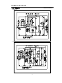
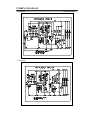
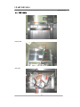
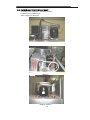
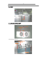
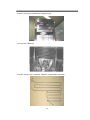
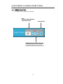
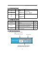
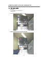
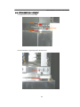
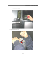
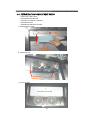
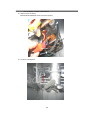
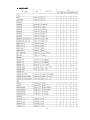
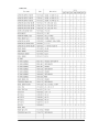
Nothing Works SMARTER for You than US !
Commercial
Refrigerator & Freezer
Service Manual
2009
TOP MOUNT REACH-IN
Model No: UMTM-23
UMTM 47
UMTM-47
UMTM-66
UMTM-23F
UMTM-47F
UMTM-66F
UMTM-47DRF
US Refrigeration
6890 Distribution Drive
Beltsville, Maryland 20705
(888) 556-2112
www.us-refrig.com
10/27/2009
TABLE OF CONTENTS
1.FEATURE CHART
1-1. FRONT VIEW(UMTM-47F)
1-2. SIDE VIEW(UMTM-47F)
2.WIRING DIAGRAM
2-1. REFRIGERATOR : UMTM-23R, UMTM-47R, UMTM-66R
2-2. FREEZER
: UMTM-23F, UMTM-47F, UMTM-66F
3.PART DETAILS
3-1. TOP PANEL
3-2. COMPRESSOR COMPARTMENT
3-3. DOOR
3-4. COOLING COMPARTMENT
4.MAIN COMPONENTS
4-1. COMPRESSOR
4-2. POWER Relay(COMP. Relay)
4-3. CONDENSER DRYER
4-4. COMPRESSOR CAPACITOR
4-5. EVAPORATOR FAN MOTOR
4-6. CONDENSER FAN MOTOR
4-7. EVAPORATOR DEFROST HEATER
4-8. LAMP BULB
4-9. MAIN PCB
4-10. DISPLAY PCB
5.ELECTRONIC CONTROL INSTRUCTIONS
5-1. FREEZER CONTROL
5-1-1. HOW TO USE THE DISPLAY PCB PANEL
5-1-2. FUNCTION & MANUAL DEFROST
5-1-3. ERROR CODE TABLE
5-1-4. SENSOR DESCRIPTION
5-2. REFRIGERATOR CONTROL
5-2-1. HOW TO USE THE DISPLAY PCB PANEL
5-2-2. FUNCTION TABLE
5-2-3. ERROR CODE TABLE
6.REPLACEMENT OF MAIN COMPONENTS
6-1. TOP PANEL PARTS
6-2. REPLACING DOOR
6-3. DOOR HINGE ADJUSTMENT
6-4. REFRIGERATION COMPARTMENT PARTS
6-5. CONDENSING UNIT
7.PART-LIST
2
1.FEATURE CHART
1-1. FRONT VIEW (UMTM-47F)
3
1-2. SIDE VIEW (UMTM-47F)
28
19 3
20
5
6
4
6 3 10
23
1
17
21
2
25
18
24
9
7
6
1
8
6
2
12
22
4
11
13
15
16
14
26
27
1
2
3
4
5
6
6
6
TOP PANEL
DOOR SWITCH
MAIN PCB
DOOR
EVAPORATOR FAN MOTOR
SENSOR
1 FREEZER C SENSOR
2 DEFROST SENSOR
8
9
10
11
12
13
14
15
6 3 REFRIGERATOR C SENSOR 16
6 4 REFRIGERATOR T SENSOR 17
18
7 LAMP BULB
LAMP SHIELD
LAMP SOCKET
EVAPORATOR DEFROST HEATER
EVAPORATOR DRAIN HOSE
EVAPORATOR DRAIN PAN HEATER
EVAPORATOR FAN MOTOR GUARD
SHELF
SHELF CLIP
SHELF STANDARD
CONTROL PANEL
TRANSFORMER
4
19 COMPRESSOR CAPACITOR
20 CONDENSER COIL
21 CONDENSER FAN MOTOR
22 CONDENSER DRYER
23 COMPRESSOR
24 CAPILLARY TUBE
25 SUCTION LINE
26 CONDENSATE DRAIN PAN
27 CASTER
2.WIRING DIAGRAM
WIRING DIAGRAM
2-1. REFRIGERATOR
● UMTM-23R
● UMTM
UMTM-47R
47R
5
2.WIRING DIAGRAM
WIRING DIAGRAM
● UMTM-47DRF
6
2.WIRING DIAGRAM
2-2. FREEZER
WIRING DIAGRAM
● UMTM-23F
● UMTM-47F
7
2.WIRING DIAGRAM
● UMTM-66F
WIRING DIAGRAM
● UMTM-66R
8
3.PART DETAILS
PART DETAILS
3-1. TOP PANEL
DOOR
LAMP
POWER
Display PCB
POWER
DISPLAY
Main PCB
POWER
MAIN
9
3-2. REFRIGERATION COMPARTMENT
- Condensing units : Compressor, Condenser Fan Motor,
Condenser Coil, Condenser Dryer.
- Others : Power-cord, Drain pan
UMTM-47R
UMTM-47F
UMTM-23F,UMTM-23
10
3-2. REFRIGERATION COMPARTMENT
Condensing Unit
UMTM-66F,UMTM-66R
UMTM-47DRF
11
3-3. DOOR
Door Gasket
GASKET
3-4. COOLING COMPARTMENT
Evaporator Housing (Duct) (UMTM-47F)
DRAI
EVAPORATO
R FAN
LAMP
Freezer Evaporator (UMTM-47F)
EVAPORATOR FAN
MOTOR
DEFROST
HEATER
EVAPORAT
OR COIL
Condensate Drain Pan
Condenser Fan Motor Assembly
Compressor Capacitor (Running & Starting Capacitor)
RUN & START
RUN CAPACITOR
13
Evaporator Housing (Duct) (UMTM-23F, UMTM-23R Type)
Coil Evaporator (UMTM-23F)
Evaporator Defrost Heater ( UMTM-23F, UMTM-47F, UMTM-47DRF, UMTM-66F)
14
4. MAIN COMPONENTS
4-1.COMPRESSOR
MODEL
Refrigerant
Voltage
Comp.Model
Part code
Starting type
MODEL
Refrigerant
Voltage
Comp.Model
Part code
Starting type
MSR-23NM
※.GST-60TF(115/208~220V/60Hz)
MSR-49NM
R-134a
MSF-49NM
R-404A
115V/60Hz
SK1A1C-L2W
CAJ2432Z(A)
R7439-110
R7430-340
CSR
CSR
HBL27YE-1
R7439-420
CSR
UMTM-23R
UMTM-47DRF
UMTM-23F
UMTM-47DRF
MSF-23NM
UMTM-47R
R-134a
MODEL
SK1A1C-L2W CAJ4476Y(A)
R7439-110
R7439-360
CSR
CSR
UMTM-66F
UMTM-66R
R-404A
R-134a
CAJ2432Z(A)
R7430-340
CSR
CAJ4476Y(A)
R7439-360
CSR
115V/60Hz
SK182C-L2U
R7439-010
CSR
SK1A1C-L2W
R7439-110
CSR
4-2.POWER-Relay(COMP. Relay)
MODEL
Voltage
Relay Model
Part code
UMTM-47F
MSR-23G-1 MSR-49G-2
R-134a
MSR-23NM
MSR-49NM
UMTM-23R
UMTM-47DRF
UMTM-23F
UMTM-47DRF
Voltage
Relay Model
Part code
※.GST-60TF(115/208~220V/60Hz)
MSF-23NM
MSF-49NM
115V/60Hz
G7L-1A-TUB
R
UMTM-47
UMTM-47F
MSR-23G-1
MSR-49G-2
UMTM-66F
UMTM-66R
115V/60Hz
G7L-1A-TUB
R
4-3.CONDENSER DRYER
MODEL
UMTM-23R
UMTM-47DRF
UMTM-23F
UMTM-47DRF
UMTM-47
UMTM-47F
UMTM-66F
UMTM-66R
Refrigerant
spec
Part code
R-134a
36GR
R2183-032
R-134a
36GR
R2183-032
R-134a
36GR
R2183-032
R-404A
407GR
R2183-100
R-404A
407GR
R2183-100
R-134a
407GR
R2183-032
4-4.COMPRESSOR CAPACITOR
MODEL
UMTM-23R
UMTM-23F
UMTM-47DRF
UMTM-47DRF
※.GST-60TF(115/208~220V/60Hz)
UMTM-47
Voltage
Running
Part code
Starting
Part code
Voltage
Motor Model
Part code
UMTM-66R
UMTM-66F
115V/60Hz
230VAC/10㎌
R7549-170
200VAC/100㎌
R7549-160
250VAC 12㎌
R7543-110
250VAC 125㎌
R7543-100
4-5.EVAPORATOR FAN MOTOR
MODEL
UMTM-47F
UMTM-23R
UMTM-47DRF
UMTM-23F
UMTM-47DRF
※.GST-60TF(115/208~220V/60Hz)
UMTM-47
UMTM-47F
115V/60Hz
IS-4420DADY
R7423-033
15
UMTM-66F
UMTM-66R
MAIN COMPONENTS
4-6. CONDENSER FAN MOTOR
MODEL
UMTM-23R
UMTM-47DRF
Voltage
Part code
UMTM-47
※.GST-60TF(115/208~220V/60Hz)
UMTM-66R
UMTM-47F
UMTM-66F
115V/60Hz
R7109-510
R7109-500
4-7.EVAPORATOR DEFROST HEATER
MODEL
UMTM-23F
UMTM-47DRF
UMTM-23R
UMTM-47DRF
Voltage
spec
Part code
UMTM-47R
UMTM-66R
※.GST-60TF(115/208~220V/60Hz)
UMTM-23F
UMTM-47DRF
UMTM-47F
UMTM-66F
445W
R7313-330
600W
R7313-411
900W
R7313-440
UMTM-23F
UMTM-47DRF
UMTM-47F
UMTM-66F
UMTM-47F
UMTM-66F
UMTM-47F
UMTM-66F
115V/60Hz
-
4-8.LAMP BULB
MODEL
UMTM-23R
UMTM-47DRF
UMTM-47
UMTM-66R
115V/60Hz
25W
Voltage
spec
Part code
R7394-010
4-9.MAIN PCB (DC12V)
MODEL
UMTM-23R
UMTM-47DRF
UMTM-47
Voltage
Part code
UMTM-66R
UMTM-23F
UMTM-47DRF
DC 12V
R7113-210
4-10.DISPLAY PCB (DC12V)
MODEL
Voltage
Part code
UMTM-23R
UMTM-47DRF
UMTM-47
UMTM-66R
UMTM-23F
UMTM-47DRF
DC 12V
R7113-210
16
5. ELECTRONIC CONTROL INSTRUCTIONS
5-1. FREEZER CONTROL
5-1-1. HOW TO USE THE DISPLAY PCB PANEL
- LED
- It indicates setting temperature,
except defrost function
- Door Open LED
- Temperature can be controlled by the user.
- Factory setting is at level "2 Ԭ". Setting can
be changed by pressing up/down button.
- Up arrow for Colder, Down arrow for Warmer.
17
ELECTRONIC CONTROL INSTRUCTION
5-1-2. FUNCTION TABLE & MANUAL DEFROST
NO
1
2
3
4
Function
Controlled
Part
Initial
Operation
Description
1. LED displays inside temperature
2. Begins to run immediately if higher than 50℉ and
begins to run after 5 minutes pause if lower
than 50℉.
1. The Temperature can be changed by pushing up/down
buttons.
2. LED displays inside temperature
3. Buzzer buzzes 1 time whenever a button is pressed
4. Compressor automatically turns on and off by C-sensor
(Except error mode)
Compresso
Temperature
5. Comp. On/off temperature at C-sensor (℉)
r
Control
Setting 5.0 3.0 1.0 -1.0 -2.0
LED
Comp On 5.0 3.2 1.4 -0.4 -2.2
Comp Off -2.2 -4.0 -5.8 -7.6 -9.4
Defrost
Function
Error
Display
Setting -3.0 -5.0 -7.0 -9.0
Comp On -3.1 -4.0 -4.9 -7.6
Comp Off -10.3 -11.2 -12.1 -13.9
1)Defrost function is controlled time interval setting.
2)Factory setting is every 8 hours.
3)If it becomes defrost cycle time, Defrost heater is
operated when D-sensor senses below 23℉.
4)Defrost heater terminates when D-sensor temperature comes
to above 53℉, then compressor will start after 10 minutes.
5)During defrost period, LED displays dF.
6)If D-sensor dose not cut off defrost heater,
Heater
main pcb has a back up for defrost time, the maximum is
Compresso
40 minutes.
r
7)Defrost can be set every 6 hours by cutting wire the
main pcb.
LED
O
8
X
6
Cut wire
1)Press `up' button 3 times with pressing and holding
`down´ button.
Above procedure switches normal display to error
display mode. And then 88 LED indicates, `(D1)' or `(F3)'
or `(C1)' respectively.
2)10 seconds after the last button pressed, error display
mode will be switched to normal display mode.
18
ELECTRONIC CONTROL INSTRUCTION
5-1-3. ERROR CODE TABLE
CODE
Content
CO
- Normal operation
- TIME CONTROL
Comp On : 10MINUTES
Comp Off : 6MINUTES
- OPEN
C-sensor
CS
(D1)
(F3)
(C1)
Refrigeration state
Perception Method
- SHORT
- OPEN
D-sensor
- SHORT
5-1-4. SENSOR DESCRIPTION
Sensor
Model
D-sensor
Freezer
Freezer
C-sensor
Role
Detect Eva coil's temp. to start and terminate
defrosting.
Detect inside air temp. to operate comp and to
indicate the inside temp. on the display PCB
Refrigerator Detect Eva coil's temp. to operate comp
T-sensor
Refrigerator
Detect inside air temp. to indicate the inside temp
on the display PCB
5-2. REFRIGERATOR CONTROL
5-2-1. HOW TO USE THE DISPLAY PCB PANEL
- LED
- It indicates inside temperature,
- Door Open LED
- Temperature can be controlled by the user.
- Factory setting is at level "35 Ԭ". Setting can
be changed by pressing up/down button.
19
Wire Color
WHT
BLK
BLK
WHT
ELECTRONIC CONTROL INSTRUCTION
5-2-2. FUNCTION TABLE
NO
Function
1
Initial
Operation
Controlled
Part
Description
1. LED displays inside temperature
2. Begins to run immediately if higher than 41℉ and
begin to run after 5 minutes pause if lower
than 41℉.
1. The Temperature can be changed by pushing up/down
buttons.
2. LED displays inside temperature
2
Temperature
Control
3. Buzzer buzzes 1 time whenever a button is pressed
Compresso
4. Compressor automatically turns on and off by C-sensor
r
(Except error mode)
LED
5. Comp. On/off temperature at C-sensor(℉)
Setting
Error
Display
LED
38
37
36
35
40.2
39.3 38.3 37.4
Comp Off 27.7
26.1
24.4 22.8 21.3
Setting
3
39
Comp On 41.0
34
32
30
28
Comp On 37.4
37.4
37.4 37.4
Comp Off 20.3
19.4
18.5 17.6
1)Press `up'
up button 3 times with pressing and holding
`down´ button.
Above procedure switches normal display to error
display mode. And then 88 LED indicates, `(D1)' or `(C1)'
respectively.
2)10 seconds after the last button pressed, error display
mode will be switched to normal display mode.
5-2-3. ERROR CODE
CODE
tO
ts
(D1)
(C1)
Content
T-sensor
C-sensor
Refrigeration state
Perception Method
- Normal operation
- OPEN
- Time control
Comp ON : 10 MINUTES
- SHORT
Comp OFF : 20 MINUTES
- OPEN
- SHORT
20
6. REPLACEMENT OF MAIN COMPONENTS
6-1. TOP PANEL PARTS
- MAIN PCB
- LOCK ASSEMBLY or POWER SWITCH
- DOOR SWITCH
A. Remove the screws located on the top of top panel.
B Remove the screws located on the bottom of top panel
B.
panel.
21
REPLACEMENT OF MAIN COMPONENTS
C. Place the top panel on top of the cabinet.
COVER PANEL
D. You can replace POWER-Relay and MAIN PCB
POWER
MAIN
22
REPLACEMENT OF MAIN COMPONENTS
E. Pull out the harness located in back of top panel.
You can replace power switch, lamp switch and display PCB.
CONTROL
23
REPLACEMENT OF MAIN COMPONENTS
6-2. REPLACING DOOR
A. Disassemble top panel as described section 6-1 A,B
B. Open the door and unscrew the bottom hinge.
Upper Hinge
HINGE
Bottom Hinge
24
REPLACEMENT OF MAIN COMPONENTS
6-3. DOOR HINGE ADJUSTMENT
A. Detailed structure of DOOR-HINGE
SCRE
Upper Hinge
DOOR
SPRING
B. Insert it between a upper hinge and a door with a tool.
TOOL
DOOR
25
REPLACEMENT OF MAIN COMPONENTS
C. Unscrew the upper hinge.
D. Remove the upper door hinge.
26
REPLACEMENT OF MAIN COMPONENTS
6-4. REFRIGERATION COMPARTMENT PARTS
- LAMP BULB, LAMP SHIELD
- EVAPORATOR FAN MOTOR
- D-SENSOR, C-SENSOR, T-SENSOR
- EVAPORATOR COIL
- EVAPORATOR DEFROST HEATER
A. Disassemble lamp shield
LAMP
LAMP
SOCKET
LAMP SHIELD
B. Disassemble duct
EVAPORATOR
DEFROST
EVAPORATOR
C. Pull out the lamp
EVAPORATOR DRAIN
27
REPLACEMENT OF MAIN COMPONENTS
D. Replacing evaporator fan motor
D-1. Disconnect the fan motor's harness.
D-2. Remove the four screws which are located on bottom of fan motor
EVAPORATOR FAN
E. Replacing sensor
E-1. FREEZER C-sensor
UMTM-FREEZER C SENSOR
E. Drain hose heater
HOSE
28
REPLACEMENT OF MAIN COMPONENTS
E-2. Defrost-sensor of freezer
Disassemble the DEFROST-sensor from the evaporator
DEFROST
E-3. C-sensor of Refrigerator
C SENSOR
29
REPLACEMENT OF MAIN COMPONENTS
E-4. T-sensor (Temperature Display Sensor) of Refrigerator
DISPLAY T
REFRIGERATOR SENSOR
DISPLAY T
30
7. PART-LIST
31
PART-LIST
32
PART-LIST


![Maximum Model service Manual.ppt [호환 모드]](http://vs1.manualzilla.com/store/data/006002079_1-f9e925e4876feffe85b493d91263fd66-150x150.png)