1
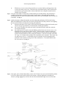
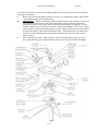
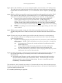
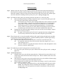
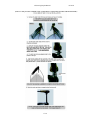
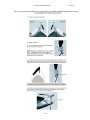
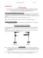
3X Steering Repair Manual
06/21/05
Section 17.
3X Steering
For step-by-step motor lower unit procedures refer to Sections 1, 2, and 13 of the Minn Kota Service Manual.
For the one-time procedure to initially orient “straight ahead” on bowmount 3X models go to page 17-10 for
BowGuard 360° models or page 17-12 for units with latch & door brackets .
Case I. Directional Indicator always stays lit.
This reed switch is usually open. With the handle bar magnet in close proximity to the reed switch, the reed
switch contacts will close and disengage power to the PWM circuit. Removing the bar magnet from close
proximity to the reed switch will open the switch contacts, energize the PWM circuit, and light the directional
indicator.
Step 1. Check to ensure that the magnet is in place in the handle pivot assembly.
Step 2. Check to ensure that the sensor bracket and on/off reed switch are in the proper position.
Case II. Steering is squeaky.
Step 1. Replace the gear carrier (P/N 2072210) and gear carrier bearing (P/N 2077320). See disassembly /
reassembly instructions below.
Disassembly / Reassembly Procedures
The complete disassembly / reassembly procedures listed here will aid the repair center when repairing any
3X Minn Kota motor. We suggest that this entire 3X repair section be read prior to starting a 3X repair
procedure.
NOTE: The basic disassembly / reassembly procedures outlines in this section apply to both transom and
bowmount, freshwater and saltwater (RipTide) 3X motors.
Fig. 1
Transom mount 3X
Fig. 2
Bow mount 3X
3X Disassembly
Step 1. Start by removing the extension handle from the inner handle by pressing down on the handle by
pressing down on the handle latch / detent button located on the top side of the handle near the control
box. With latch button depressed, slide the extension handle off and clear of the inner handle. (see
Fig. 3, page 17-2)
Step 2. Remove the six Phillips, pan head screws (#6-20 x 5/8”) located on the underside of the control box
assembly. (2 screws at front, middle, and rear of control box) (see Fig. 3, page 17-2)
17- 1
3X Steering Repair Manual
06/21/05
With the cover screws removed the control box cover can be lifted up and tipped to the side
to access the battery meter wires. Disconnect the red and black battery meter leads from the
speed selector (on 5-speed models) or the red and black wires exiting the control board on
variable-speed 3X motors.
Step 3. Lift up the inner handle assembly along with the handle pivot, handle bearing, and potentiometer
(variable-speed motors) or speed selector switch (5-speed motors). Disengage the inner handle
assembly from the “D” shaft on the potentiometer/switch, remove the inner handle, and set it aside for
reassembly. (see Fig. 3)
A.
Step 4. At this point prior to further disassembly, note the routing and positioning of all electrical wiring.
When reassembling the 3X motor the wires must be placed back in the same position to avoid getting
the wires in the circular rack and pinion steering gear mechanism.
A.
Disconnect the motor wires, battery leads, and directional indicator light leads from the speed
selector switch (5-speed motors) or control board (variable-speed motors).
A-1.
On 5-speed 3X models, the switch can easily be separated from the control box when the
wires are disconnected.
A-2.
On variable-speed 3X models, loosen the Phillips pan head screw (P/N 2073414, #6-32 x 3/8”)
holding the P/N 2071905 sensor bracket in place. (Sensor bracket is located in control box
along side the potentiometer support.) Loosening the screw allows removal of the magnetic
on/off reed switch attached to wires exiting the control box. (On/off reed switch is the small
5/8” long, 3/16” diameter black cylinder with 2 small black wires attached.) Then remove the
two P/N 2073416, #8-32 x ½” socket head cap screws (located in recessed openings on the
underside of the control box) using a 9/64” allen wrench/driver. The control board is then
free to be removed. (see Fig. 3)
Fig. 3
Step 5. Once again, prior to further disassembly, note how the 3X motor wires are routed and held in position
by the wire clamp located on the coupler socket retainer / indicator light bracket assembly P/N
2992900. (see Fig. 4, page 17-3) Also note how the directional indicator light wires are twisted and
17- 2
3X Steering Repair Manual
06/21/05
wire tied to the motor wire to prevent the indicator light wires getting in the circular rack and pinion
steering gear mechanism.
A.
Remove the P/N 2372100 phillips head screw (#8-18 x 5/8”) holding the retainer / light bracket
/ wire clamp assembly P/N 2992900 in place.
B.
IMPORTANT – With the control box parallel to the motor lower unit, note how two sides of
the hexagon ID of the coupler socket (P/N 2070800 black coupler socket for bow mount
motors, P/N 2070801 white couple socket for transom mount motors) are parallel to / in-line
with the control box pivot screws (P/N 2073408). When reassembling a 3X motor, the coupler
socket (which drives the directional indicator) must be repositioned in this exact same manner
for proper orientation of the directional indicator arrow. (Directional arrow is parallel to the
motor lower unit pointing towards the direction of boat travel when in the water with the
motor running.)
C.
After removing the retainer / light assembly, remove the coupler socket, idler gear, idler
plate, and preload ring (P/Ns 2070800/2070801, 2072215, 2071900, and 2073000). (see Fig. 4)
Fig. 4
17- 3
3X Steering Repair Manual
06/21/05
Step 6. Remove the two P/N 2332101 #8-32 x ½” tilt stop bracket / detent block retaining screws, then remove
-the P/N 2072815 bracket and P/N 2072810 detent block. (see Fig. 4, page 17-3)
Step 7. Remove the two soft plastic pivot knob covers (P/N 2070117 or 2070118) to expose the two ¼-20 x 7/8”
Phillips head screws (P/N 2073408) that hold the pivot know and control box assembly on the gear
carrier (P/N 2072210) / pivot yoke (P/N 2071512 or 2072513) assembly. (see Fig. 4, page 17-3)
Removing the two P/N 2073408 screws (these two screws go in to two nyloc nuts located
A.
inside the gear carrier) will allow the control box assembly, pivot knobs, and bushings to be
separated from the gear carrier and yoke pivot assembly. (see Fig. 4, page 17-3)
Step 8. With the control box assembly removed, unscrew the 5/16” x ½” socket head, shoulder shank cap
screw (P/N 2073400) that is located in the center of the gear carrier (P/N 2072210). (A 5-32” allen
wrench / driver is required.) (see Fig. 4, page 17-3)
A.
Remove the cap screw along with the washers, then remove the two P/N 2303412 #6-20 x 5/8”
Phillips head screws and P/N 2071714 washers that serve to guide/retain the gear carrier on the
pivot yoke. (see Fig. 4, page 17-3)
B.
With the cap screw and 2 phillips head screws removed, the gear carrier can be removed from
the pivot yoke followed by the gear carrier bearing. For reassembly, note that this bearing is
split and that the split ends key onto a rib located on the inside circumference of the pivot
yoke.
Fig. 5
17- 4
3X Steering Repair Manual
06/21/05
Step 9. Remove the collar halves (P/N 2261622) clamped around the motor inner tube (1-1/8” diameter tube).
The collar halves are located just below the lower collar (P/N 2071500) on the outer tube of either the
transom mount or bowmount 3X motor. (A 3/16” allen wrench / driver is required.) (see Fig. 5, page
17-4)
Step 10. With the collar halves removed, the motor lower unit and inner tube assembly can be pushed / lifted
up to expose the 4-hole collar (P/N 2071560) and four #8-32 x 7/16” Phillips flathead countersunk
screws (P/N 2223468) that hold the pinion gear assembly into the inner tube. (see Fig. 5, page 17-4)
Remove the four screws (P/N 2223468) to allow removal of the pinion assembly (P/N
A.
2992205), upper bearing (P/N 2077305) and 4-hole collar. (see Fig. 5, page 17-4)
NOTE: The four pinion assembly retaining screws are held in place with LocTiteTM during
B.
assembly. Removal may require heat application to the screw head. When reassembling a
3X motor, LocTiteTM primer and #603 compound MUST be reapplied to these four retaining
screws.
With the four retaining screws removed the pinion assembly, upper bearing, and 4-hole collar
can be removed.
Step 11. With the pinion assembly, bearing, and 4-hole collar removed, the motor lower unit / inner tube
assembly along with the lower collar (P/N 2071500) can be slid down and out the bottom of the outer
tube.
Step 12. To remove the pivot yoke from the upper end of the outer tube, loosen the ¼-20 socket head cap
screw and nyloc nut that serves to clamp the pivot yoke on to the outer tube. Loosen the steering
tension knob (P/N 2070105).
A.
With the screw and nut loose the pivot yoke (P/N 2071512 or P/N 2071513) can be lifted up and
off the outer tube. NOTE: When removing the pivot yoke, note its position / orientation on
the outer tube.
A-1.
On transom mount 3X motors, the steering tension knob is positioned towards the
bracket clamp screws.
A-2.
On bow mount 3X motors, the steering tension know is toward the boat when
mounted and positioned for installation of the bow mount orientation collar.
A-3.
Also, note that a tube key (P/N 2076700) is used to properly position the pivot yoke in
relation to the slots / grooves in the outer tube.
Step 13. For further disassembly / replacement of the transom bracket or BowGuard 360º assembly, the outer
tube (or outer tube and pivot yoke assembly) can be slid out of the transom bracket hinge or
BowGuard 360º.
A. On transom mount 3X motors, note that a tension block (P/N 2072800) is located between the
outer tube and the orientation collar on the transom bracket. This block will fall out of place
when the outer tube is removed from the bracket hinge. Be sure to re-install this part when
reassembling a 3X transom mount model.
This concludes the basic disassembly procedures for 3X transom and bow mount, fresh and saltwater motors.
3X motor lower unit trouble shooting, disassembly, and repair procedures are the same as all other Minn Kota
5-speed or variable speed motor units.
For re-assembly instructions go to page 17-6.
17- 5
3X Steering Repair Manual
06/21/05
3X Reassembly
Step 1. With the outer tube and pivot yoke properly positioned and slid into the transom bracket hinge or
BowGuard 360º assembly (reference Disassembly Procedure Step 12), slide the motor lower unit,
inner tube assembly, and lower collar (P/N 2071500) back into place in the outer tube with the upper
end of the inner tube extending out the top of the pivot yoke. (see Fig. 5 on page 17-4)
Step 2. Re-install the 4-hole collar, upper bearing, and pinion assembly on / in the inner tube.
A.
Prior to installing the pinion assembly, examine the upper / top end of the pinion gear teeth.
B.
Two of the gear teeth will have small raised bumps.
A-1.
On transom mount 3X motors when looking straight down at the control box area and
lower unit assembly, rotate the nose of the lower unit into the 12 o’clock position
(prop in the 6 o’clock position). On the pinion assembly, the two teeth with the
raised bumps need to be oriented towards approximately the 9 o’clock position.
A-2.
On bow mount 3X motors the two teeth with the raised bumps need to be oriented
toward the prop end of the motor lower unit when installed in the inner tube.
Examine the four pinion assembly retaining screws (P/N 2223468) for any damage. Replace
them with new screws as needed.
B-1.
Re-apply LocTite primer and LocTite #603 compound, then insert and tighten the
screws securely into the 4-hole collar, inner tube, and pinion gear assembly.
Step 3. Place the outer tube / pivot yoke assembly and inner tube, upper bearing, and pinion gear assembly
back into their normal assembled positions. (Normal assembled position is with the upper bearing
supported in its recessed area of the pivot yoke.)
A.
Slip the lower collar (P/N 2071500) up into place on the lower end of the outer tube.
A-1.
Re-install the collar halves (P/N 2261622) on the inner tube using the two ¼-20 x 1”
socket head cap screws.
A-2.
Slide the collar halves up against the bottom of the lower collar and tighten the collar
screws to secure the collar in place.
Step 4. Re-install the gear carrier bearing (P/N 2077320) in the pivot yoke.
A.
Use care to line up the rib in the pivot yoke with the ends of the split gear carrier. (see Fig. 5,
page 17-4)
Step 5. Transom mount motors A.
Align the motor lower unit with the transom bracket. Position the lower unit with the “nose”
B.
C.
of the motor towards the transom bracket clamp screws. Block or hold the motor lower unit
in this position.
Place the gear carrier (P/N 27702210) into position in the pivot yoke with the tilt detent spring
(P/N 2072705) towards the prop end of the motor lower unit.
While looking at the two pinion gear teeth with the raised bumps, count five teeth clockwise
and you will see a raised rib / dash.
C-1.
The tooth with the raised dash must line up with the timing mark in the gear carrier.
NOTE: The timing mark used for transom mount 3X models is a small raised rib
located at the 1:30 o’clock position on the inside circumference of the gear carrier.
(see Fig. 6, page 17-7)
17- 6
3X Steering Repair Manual
06/21/05
Fig. 6
Bow mount motors –
A.
Align the motor lower unit with the prop end on the same side as the steering tension knob in
B.
C.
the pivot yoke. Block or hold the motor lower unit in this position.
Place the gear carrier (P/N 27702210) into position in the pivot yoke with the tilt detent spring
(P/N 2072705) towards the “nose” of the motor lower unit.
Align the two pinion gear teeth with the raised bumps (on bow mount 3X models these two
teeth will be oriented toward the prop end of the motor lower unit) with the timing mark in
the gear carrier.
NOTE: The timing mark used for bow mount 3X models is a raised bump on the gear tooth.
(Located in the 12:00 o’clock position when the gear carrier is held with the detent spring
towards the viewer and viewed from above.) (see Fig. 7)
Fig. 7
Step 6. With the gear carrier in its proper location and position (relative to the appropriate timing marks), reinstall the socket head cap screw (P/N 2073400) and washers. Blue LocTite is recommended on this
screw. Tighten screw with a 5/32” allen wrench / driver.
A.
Re-install the two #6–20 x 5/8” phillips head screws (P/N 2303412) and washers (P/N 2071714)
that retain / guide the gear carrier on the pivot yoke.
Step 7. Re-install the control box with bushing and pivot knobs on to the gear carrier pivot yoke assembly.
(see Fig. 4, page 17-3)
A.
Position the control box so that the handle end of the box is opposite the tilt detent spring in
the gear carrier.
17- 7
3X Steering Repair Manual
B.
C.
06/21/05
Examine the pivot knobs in the area where they contact the gear carrier. Note the two flat
surfaces on both edges of the pivot knob shank. These two flats must be aligned with the two
ribs along side the hole in the gear carrier for the pivot knob screws (P/N2073408).
With the control box, bushing, pivot knobs, pivot knob screws, and nyloc nuts in their proper
position, securely tighten the two ¼-20 x 7/8” phillips head pivot knob screws.
C-1.
The two soft plastic pivot knob covers can be re-installed at this time. Note the flat
surfaces on the outer edge of the pivot knob as they serve to “key” the pivot knob
covers to prevent their rotation.
Step 8. Re-install the tilt detent block (P/N 2072810) in the control box (teeth towards the detent spring)
followed by the tilt stop bracket (P/N 2072815) and the two #8-32 x ½” phillips head screws that are
used to attach both parts to the control box.
Step 9. Re-install the preload ring (P/N 2073000), idler plate (P/N 2071900) idler gear (P//N 2072215), and
coupler socket (P/N 2070800 or P/N 2070801). (White coupler socket for transom mount motors and
black coupler socket for bow mount motors.)
A.
As noted during disassembly, position the coupler socket so that any two parallel sides of the
hexagon I.D. of the coupler socket are as close as possible to being parallel to the control box
pivot screws.
Coupler Socket
Pivot Screws
Step 10. Re-install the control board or 5-speed switch using the fasteners or parts removed during disassembly. (see Fig. 3, page 17-2)
Reconnect motor wires, battery leads, directional indicator light wires, and (if a variable
A.
B.
C.
D.
E.
speed unit) place the on/off reed switch back in its proper location. Tighten the sensor
bracket screw to secure reed switch.
NOTE: if connections were sealed with heat shrink tubing prior to disassembly they MUST
be resealed with new heat shrink!
Re-install the inner handle assembly. Start by engaging the “D” hole in the handle pivot on
the “D” shaft of the potentiometer or 5-speed switch. Then place the handle pivot, inner
handle, and handle bearing in their proper location. (Note that the triangular shaped arrow on
the handle bearing is on top.)
Reconnect the red and black battery meter leads to the appropriate wires (exiting the control
board on variable speed motors or switch on 5-speed motors).
NOTE: the red and black battery meter wires must be routed to the side of the control box
cover and pushed in to the slots in the cover ribs prior to installing the cover on the control
box.
Also prior to cover re-installation, line up the directional indicator with the motor lower unit.
(The directional arrow points toward the “nose of the motor lower unit.)
Position cover in place on control box and secure with the six #6-20 x 5/8” phillips head
screws (P/N 2303412).
17- 8
3X Steering Repair Manual
06/21/05
Step 11.Re-install extension handle and test the motor for proper full range 3X steering function to make sure
that nothing is binding or restricting the steering system.
Connect the motor battery leads to the appropriate voltage and test run for speed variation and
function. Test the battery meter for proper function. Test the control box tilt adjustment for
proper range and travel. Check and verify overall motor operation and function.
A.
This concludes the basic 3X motor re-assembly procedures. Further step-by-step repair procedures will be
added as needed when field service issues arise
17- 9
3X Steering Repair Manual
06/21/05
(This is a 1-time procedure to initially orient “straight ahead” on bowmount 3X models with BowGuard 360°.)
17-10
3X Steering Repair Manual
End of procedure.
17-11
06/21/05
3X Steering Repair Manual
06/21/05
(This is a 1-time procedure to initially orient “straight ahead” on bowmount 3X models with latch & door mounts.)
17-12
3X Steering Repair Manual
End of procedure.
17-13
06/21/05