1
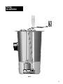
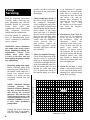
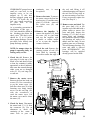
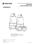
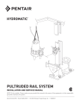
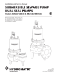
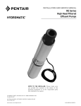
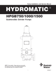
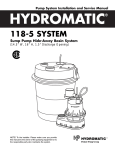
Pump Installation and Service Manual HYDROMATIC ® OSP33 Submersible Sewage Ejector Pump NOTE! To the installer: Please make sure you provide this manual to the owner of the pumping equipment or to the responsible party who maintains the system. General Information Thank you for purchasing your HYDROMATIC Pump. To help insure years of trouble free operation, please read the following manual carefully. Before Operation: Read the following instructions carefully. Reasonable care and safe methods should be practiced. Check local codes and requirements before installation. Attention: This manual contains important information for the safe use of this product. Read this manual completely before using this product and refer to it often for continued safe product use. DO NOT THROW AWAY OR LOSE THIS MANUAL. Keep it in a safe place so that you may refer to it often. WARNING: Before handling these pumps and controls, always disconnect the power first. Do not smoke or use sparkable electrical devices or flames in a septic (gaseous) or possible septic sump. Pump Warning To reduce risk of electrical shock: 1. Risk of Electrical Shock: This pump has not been investigated for use in swimming pool areas. 2 2. Risk of Electrical Shock: Connect only to a properly grounded receptacle. Septic tank to be vented in accordance with local plumbing codes. Do not smoke or use sparkable electrical devices or flame in a septic (gaseous) or possible septic sump. If a septic sump condition may exist’s and if entry into sump is necessary, then (1) provide proper safety precautions per OSHA requirements and (2) do not enter sump until these precautions are strictly adhered to. Do not install pump in location classified as hazardous per N.E.C., ANSI/NFPA 70 - 1999. Failure to heed above cautions could result in injury or death. Installation Instructions These important instructions must be followed for satisfactory performance of your pump: 1. Provide proper sump (recommended minimum sump diameter is 18"). 2. Do not set pump directly on the bottom of the sump if it is not solid. Raise the pump by placing bricks or concrete blocks underneath it. 3. Make sure sump is free of string, cloth, nails, gravel, etc. before installing pump. 4. Pump to be connected to a properly grounded, grounding type receptacle only. 5. Do not remove ground pin from electrical plug. 6. Do not use an extension cord. 7. For proper automatic operation, make sure the pump power cord is plugged into the “piggy-back” receptacle on the diaphragm switch cord. 8. Connect to separate electrical circuit taken directly from main switch. 9. Use steel or plastic pipe for all connecting lines between pump and sewer outlet. NOTE: Some city regulations do not allow installing a pump with plastic pipe. Check local regulations. 10.In applications where the pump may sit idle for months at a time, it is recommended that the pump(s) be cycled every month to insure the pumping system is working properly when needed. 11.HYDROMATIC check valve should be installed in discharge pipe at least 12" above the discharge outlet of the pump. 12.An audible alarm, such as the Q Alert system for high water conditions, should be installed in every pump for greater protection. NOTE: The Q Alert panel is for indoor use only. For outdoor application contact your HYDROMATIC distributor for additional Q panels. Pump Installation OSP33 3 Read the following instructions carefully before replacing any parts. Reasonable care and safe methods should be practiced. Check local codes and requirements before installation. Only competent electrician should make the installations. Servicing should be performed only by knowledgeable pump service contractors or authorized service stations. WARNING: Always disconnect the pump from power source before handling or making any adjustments. Always wear rubber boots when there is water on the floor and you must unplug the pump or make any adjustments. 1. Removing pump from sump. Before removing pump from sump for repair, check to see if the trouble could simply be a blown fuse, tripped circuit breaker, or a power cord not completely inserted into the receptacle. NOTE: Automatic thermal overload protects the sealed-in oil motor. Running dry may overheat the motor and activate the overload protector. This will close the circuit when the motor cools and allow pump to restart. If condition continues to exist, it may cause premature pump failure. Unplug the power cord and pull the pump, by the handle, from the sump. Sandblast, if 4 possible, any dirt or trash from the outside of the pump before dismantling. 2. Check diaphragm switch. If the unit is being operated by the automatic diaphragm switch, unplug the pump from the “piggyback” receptacle and plug the pump directly into the power source. If the pump starts each time it is plugged directly into the receptacle and does not start each time when plugged into the piggyback switch with the diaphragm switch pressed into a start position, replace the complete piggyback switch assembly and retest with the new assembly. 3. Check for impeller blockage. Check for an obstruction in the impeller cavity by laying the pump on its side and inserting a screwdriver through the hole in the foot and baffle plate (28) and the bottom plate (26) and turning the rotor and shaft (16). It should turn freely. If the impeller hangs up or there is an indication of impeller blockage, the foot and baffle plate must be removed by removing the three hex head cap screws (29) and the bottom plate removed by removing the five hex head cap screws (27). Clear the impeller of its obstruction and clean the impeller, and reassemble. 4. Check power cord. Check the power cord (5) for brittleness or for any cuts or nicks in the insulation. Using an ohmmeter, check the continuity of the power cord. If any of these tests fail, the power cord should be replaced. To replace power cord unscrew the nut on the cord, pull cord up and discard damaged power cord. Add pipe sealant to threads and reinstall by pushing cord onto pins and tighten nut. 5. Check for air lock. A sump pump is said to be air locked if water traps in the pump and it cannot get out, thus preventing pump from operating. 32 TOTAL DYNAMIC HEAD-FEET Pump Servicing 24 1/3 HP 16 8 0 0 10 20 30 40 CAPACITY-U.S. G.P.M. 50 60 it must 9. Remove the stator. To remove the stator, remove the four hex head screws (12) and the stator plate (13). Lift the stator off the volute case (21) and set aside. 11.Check the seal. Remove the rotating portion of seal (24) from shaft by inserting a screwdriver under the edge of OVE T REM DO NO TAG THIS d ANT ! IMPORTOWNER TO NOTE TION REPAIR STA ty and attach to Warran Clip on dotted line clipped portion must Repair Report. The to for repairs to be be attached in order ;;;;;;;; ;;;;;;;; ;; ;; ;;;;;;;; ;;;;;;;; ;; ;; ;; ;; ;;;;;;;; ;;;; ;;;; ;;;;;;;; ; ;;;;; ;; ;; ;; ;;;;;;;; ;;;; ;; ;;;; ;;;;;;;; ;;;; ;;;;; ; ; ;;;; ;;;;; ; ; ;;;;;;;;;;;;; ;;;; ;;; ;;;;;;;; ;;; ;;;; ;;;;; ; ;;;;;;;; ;;;;;; ;;; ;;; 5 3 4 13 2 1 18 7 6 7 ;;;;; 14 32A 17 15 ;;; ;;;; 29 19 16 31 22 33 10 11 ;;;;;;; ; ; ; ; ; ;;;;;; ;;;;;; ; ; ; ;;;; 17 32 9 ;;; ;;;; 12 ; ;;; ;;; ; 8. Check for short. Disconnect the stator leads (7, 8, 9) from the connector (6). Use an ohmmeter to check the continuity of the stator. If stator fails to pass the 12.Remove rotor and shaft. Tap the rotor shaft (16) at the impeller end of the shaft with a plastic mallet to remove the rotor and shaft. Inspect the bearings (17). If they do not rotate freely and smoothly, they should be replaced. When new bearings are ready to be added onto the shaft, do not push on outer race of bearings. This will damage bearings. If a rotor and shaft is ordered from HYDROMATIC, the bearings will be supplied already pressed on the shaft. 10.Remove the impeller. To remove the impeller (25), hold the rotor (16) in your hand and tap the impeller with a plastic or rubber mallet so as to turn the impeller counter clockwise. 6. Check the oil. Remove the pipe plug (4) in the top of the motor cover and drain oil into a clean, dry container. A milky appearance to the oil indicates that water has entered through either worn out or damaged seals (23, 24), seal ring (20), or cord nut. 7. Remove the motor cover. Remove the four hex head cap screws (22). Use a screwdriver to pry the motor cover (19) from the volute case (21) at the fastening ears, being careful not to cut the seal ring (20) with the screwdriver or crack the motor cover. Lift the motor cover until it clears the stator (15). the seal and lifting it off without damaging seal. Inspect the seal face for any nicks or an uneven seating of seal face. If any are present, replace the seal. (See Step 14.) Certifie NOTE: In sumps where the pump is operating daily, air locking rarely occurs. continuity test, be replaced. SPMA HYDROMATIC pumps have a small air vent hole in the impeller cavity to let out trapped air. If this hole becomes plugged, pump may air lock. To break the air lock, use a small screwdriver to clear hole in the impeller cavity. As a secondary precaution in installations of this type — 1⁄16" hole should be drilled in the discharge pipe below the check valve. The check valve should be 12 to 18 inches above pump discharge. Do not put check valve directly into pump discharge opening. 20 30 ;¢¢ @@ ÀÀ ;; QQ ; ;¢¢ @@ ÀÀ ;; QQ ; ;¢¢ @@ ÀÀ ;; QQ ; ;¢¢ @@ ÀÀ ;; QQ ; ;; ;; ;; ;;;; ;; ;;;; ;; ;; 28 23 24 27 21 26 5 Pump Servicing 13.Remove seal. Remove the old stationary portion of the seal (23) from the case (21) by inserting a screwdriver into the seal housing of the case from the top of the case and tapping lightly with a hammer. Clean the seal area of the case with a clean cloth. 14.Reinstall the rotor and shaft assembly. Push on outer race to seat bearing in volute case. 15.Reinstall seal. Apply an oil lubricant to the new stationary portion of the seal (23) and press into the case (21). Coat the new rotating portion of seal with lubricant and press into place on the rotor shaft with the rubber ring facing the impeller. 16.Reinstall impeller. Add a drop of Locktite 277 to the shaft and screw the impeller on hand tight. The impeller will force the rotating portion of seal into position. 17.Replace seal ring. Remove the old square seal ring (20) from the volute and stretch on a new ring coated with O-ring lube. Do not roll the ring onto the volute or improper seating and water leakage into the motor housing will result. 6 18.Reinstall the stator. Place the stator (15) in the volute case (21) so the stator bolt holes line up. Lay the stator plate (13) on the stator (15) and line up with stator bolt holes. Put in the stator bolts (12) and tighten evenly to prevent cocking of the stator. Push the connectors of the power cord onto the stator terminals. 19.Reinstall motor housing. Tighten down the four hex head cap screws (22) evenly to prevent cocking of motor housing and achieving an uneven seal on the seal ring (20). 20.Oil. Fill the motor cap with high grade transformer oil such as Sohio Factopure SE40 oil or equivalent to at least 1⁄4" over motor windings (.38 gallon). Do not fill the motor housing completely — allow airspace for oil expansion. 21.Reinstall oil pipe plug. Coat pipe threads with thread sealant before installing. 22.Check pump. Plug the power cord into a grounded outlet and start pump by applying pressure to the switch diaphragm (automatic only — manual should start when power is applied). Motor should run smoothly, be free of vibration and stop when pressure is removed. OSP33 Parts List Certifie OVE T REM DO NO TAG THIS SPMA d ANT ! IMPORTOWNER TO NOTE TION REPAIR STA ty and attach to Warran Clip on dotted line clipped portion must Repair Report. The to for repairs to be be attached in order ;;;;;;;; ;;;;;;;; ;; ;; ;;;;;;;; ;;;;;;;; ;;;; ;;;; ;;;;;;;; ;;;; ;;;; ;;;;;;;; ;;; ;;;;; ;;;; ;;;;;;;; ;;;; ;; ;;;; ;;;;;;;; ;;;;;;;;; ; ; ;;;; ;;;;; ; ; ;;;;;;;;;;;;; ;; ;;; ;;;;;;;; ;; ;;; ;;;; ;;;;; ; ;;;;;;;; ;;;;;; ;; ;;; ; 5 3 4 13 2 18 1 7 6 7 ;;;;; ;;; ;;;; 17 ;;;;;;; ; ; ; ; ; ;;;;;; ;;;;;; ; ; ; ;;;; 12 14 32 32A 17 ;;; ;;;; 1 1 2 3 4 5 5 5 6 7 9 10 11 12 13 *14 15 15 16 17 18 Part No. ;; ;;;; 4580-001-1 60-000-5 119-002-1 12585-004-5 12585-005-5 12585-003-5 4209-004-5 6000-061-5 6000-060-5 12845-001-1 995-002-1 145-003-1 70-000-1 13348-001-1 13349-000-1 9994-001-1 13348-011-5 13349-010-1 65-001-1 64-001-1 Nameplate, 115V Nameplate, 230V Drivescrew Handle Pipe Plug Power Cord Assembly, 115V-10' Power Cord Assembly, 115V-20' Power Cord Assembly, 230V-20' Connector Assembly Lead Wire/Terminal Assembly (Blk, 625") Grnd Wire/Terminal Assembly (Grn, 5") Screw, 8-32 Self Tapping Lockwasher, #8 Bolt, Stator - 8-32 x 55/8" Lg. (Prior to 11/90) Plate, Stator (Prior to 11/90) Oil Stator, 115V Date Code 11/90 Stator, 230V Rotor & Shaft w/Bearings Date Code 11/90 Bearing Load Spring 20 30 ;; ;; ;;;; 29 Description 15 ;;¢¢ @@ ÀÀ ;; QQ ;; ;;¢¢ @@ ÀÀ ;; QQ ;; @@ ÀÀ ;; QQ ¢¢ @@ ÀÀ ;; QQ ¢¢ ;; ;; ;; ; ;;; ;;; ; Ref. No. 19 16 31 22 33 9 10 11 28 23 24 Qty. Ref. No. 1 1 2 1 1 1 1 1 1 1 1 1 1 4 1 .38 gal. 1 19 1 1 2 1 Part No. 20 21 22 23 24 25 26 27 28 29 30 56-008-2 56-026-2 77-003-1 12328-002-2 101-007-1 83-002-1 83-007-1 16-000-2 18-002-1 19-002-1 21-000-2 19-004-1 12185-001-1 31 32 32A 33 33 33 33 33 33 5502-004-1 176-015-1 995-008-1 12752-004-5 12752-005-5 12752-006-5 12752-008-5 12752-009-5 12752-010-5 27 21 26 Description Housing, Motor Date Code 11/90 Seal Ring Volute Bolt, 5/16-18 x 1" Lg. Seal (Stationary Seat) Seal (Rotating Seat) Impeller Bottom Plate Screw, 10-24 x 3/8" Lg. Foot & Baffle Plate Screw, 10-24 x 5/8" Lg. Reducer Bushing, 2" x 1-1/2" AUTOMATIC MODELS Bracket Screw, 1/4-20 x 3/8" Lg. Lockwasher Diaphragm Switch (6-1/2" Range), 115V-10' Diaphragm Switch (6-1/2" Range), 115V-20' Diaphragm Switch (6-1/2" Range), 230V-20' Diaphragm Switch (8-1/2" Range), 115V-20' Diaphragm Switch (8-1/2" Range), 115V-20' Diaphragm Switch (8-1/2" Range), 115V-20' *Purchase locally. Qty. 1 1 1 4 1 1 1 1 5 1 3 1 1 1 1 1 1 1 1 1 1 7 WARRANTY HYDROMATIC Pumps warrants to the original purchaser of each HYDROMATIC Pump product(s) that any part thereof which proves to be defective in material or workmanship within one year from date of installation or 18 months from manufacture date, whichever comes first, will be replaced at no charge with a new or remanufactured part, F.O.B. factory. Purchaser shall assume all responsibility and expense for removal, reinstallation and freight. Any item(s) designated as manufactured by others shall be covered only by the express warranty of the manufacturer thereof. This warranty does not apply to damage resulting from accident, alteration, design misuse or abuse. If the material furnished to the Buyer shall fail to conform to this contract or to any of the terms of this written warranty, HYDROMATIC Pump shall replace such nonconforming material at the original point of delivery and shall furnish instruction for its disposition. Any transportation charges involved in such disposition shall be for the Buyer’s account. The Buyer’s exclusive and sole remedy on account or in respect of the furnishing of material that does not conform to this contract, or to this written warranty, shall be to secure replacement thereof as aforesaid. HYDROMATIC Pump shall not in any event be liable for the cost of any labor expended on any such material or for any incidental or consequential damages to anyone by reason of the fact that such material does not conform to this contract or to this written warranty. ALL IMPLIED WARRANTIES, INCLUDING THE IMPLIED WARRANTY OF MERCHANT-ABILITY AND THE IMPLIED WARRANTY OF FITNESS FOR A PARTICULAR PURPOSE, ARE LIMITED IN DURATION TO THE SAME EXTENT AS THE EXPRESS WARRANTY CONTAINED HEREIN. Some States do not allow limitations on how long an implied warranty lasts, so the above limitation may not apply. MANUFACTURER EXPRESSLY DISCLAIMS AND EXCLUDES ANY LIABILITY FOR CONSEQUENTIAL OR INCIDENTAL DAMAGES FOR BREACH OF ANY EXPRESS OR IMPLIED WARRANTY ARISING IN CONNECTION WITH THIS PRODUCT. INCLUDING WITHOUT LIMITATION, WHETHER IN TORT, NEGLIGENCE, STRICT LIABILITY CONTRACT OR OTHERWISE. Some States do not allow the exclusion or limitation of incidental or consequential damages, so the above limitation or exclusion may not apply to you. PUMP MUST BE REPAIRED BY AUTHORIZED HYDROMATIC REPAIR CENTER OR WARRANTY WILL BE VOID. IF REPAIR CENTER IS NOT AVAILABLE, RETURN PUMP TO PLACE OF PURCHASE. This warranty gives you specific legal rights, and you may also have other rights which vary from State to State. © 2001 Hydromatic®, Ashland, Ohio. All Rights Reserved. – Your Authorized Local Distributor – 1840 Baney Road Ashland, Ohio 44805 Tel: 419-289-3042 Fax: 419-281-4087 www.hydromatic.com ISO 9001 Certified Part# 5625-247-1 Item# W-03-247 8M 1/01