1
MT5519
Telescopic Handler
Operator/Service Manual
Catalog 50960067 Revision B
Beginning with S/N 25144
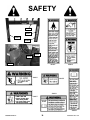
Indicator and Control Symbols
Read Operator’s Fasten Seat Belt
Manual
Safety Alert
Symbol
Engine Oil
Hydraulic Oil
Axle Oil
Brake Fluid
Diesel Fuel
Grease
Battery
Engine Electrical
Preheat
Engine Oil
Pressure
Engine Coolant
Temperature
Engine Failure
Engine Air Filter
Restiction
Hydraulic Filter
Restriction
Transmission
Temperature
Parking Brake
Brake Failure
Hourmeter
Fuel
Ignition Off
Ignition ON
Engine Start
Volume Full
Volume Half Full
Volume Empty
Horn
Lift Point
Tie Down Point
Female Auxiliary
Hydraulic Coupler
Male Auxiliary
Hydraulic Coupler
Crab Steer
2-Wheel Steer
4-Wheel Steer
Lower Load
Tilt Rearward
Tilt Forward
Retract Load
Extend Load
Raise Load
Slow
Fan
Wiper/Washer
Hazard Flasher
Turn Signals
Lights
Work Lights
Beacon
Forward
Neutral
Reverse
Front Axle
Alignment
Rear Axle
Alignment
Control Lever
Multi-Function
Audible Alarm
OFF
Manitou Americas, Inc.
One Gehl Way
P.O. Box 179
West Bend, WI 53095-0179
MT5519
Telescopic Handler
Operator/Service Manual
Catalog 50960067 Revision B
Beginning with S/N 25144
For parts orders contact your Manitou Americas Dealer or call:
Factory Parts Department (262) 334-6653.
Website: www.manitou.com / www.mnadealers.com
THIS OPERATOR’S MANUAL IS
PROVIDED FOR OPERATOR USE
DO NOT REMOVE
FROM THIS MACHINE
Do not start, operate or work on this machine until you have carefully read and thoroughly understand the contents of the operator’s manual.
Failure to follow safety, operating and maintenance instructions could result in serious injury to the operator or bystanders, poor operation, and costly breakdowns.
If you have any questions on proper operation, adjustment or maintenance of this
machine, contact your dealer or the service department of Manitou Americas Inc.
before starting or continuing operation.
California Proposition 65 Warnings
Diesel engine exhaust and some of its constituents are known to the State of
California to cause cancer and birth defects or other reproductive harm.
Battery posts, terminals and related accessories contain lead and lead compounds, chemicals known to the State of California to cause cancer and birth
defects or other reproductive harm. Wash hands after handling battery.
IDENTIFICATION INFORMATION
Write your Manitou Americas Inc. Telescopic Handler Model and Serial Numbers below.
Refer to these numbers when inquiring about parts or service from your Manitou Americas Inc. dealer.
MODEL NO.
MT5519
SERIAL NO.
The model and serial numbers for this machine are on a decal located inside the operator’s station.
Table of Contents
Chapter
Description
Page
International Symbols . . . . . . . . . . . . . . . . . . . . . . . . . . . .Inside Front Cover
1
2
3
4
5
6
7
8
9
10
Introduction . . . . . . . . . . . . . . . . . . . . . . . . . . . . . . . . . . . . . . . . . . . . . . . . . .2
Specifications . . . . . . . . . . . . . . . . . . . . . . . . . . . . . . . . . . . . . . . . . . . . . . . . .4
Checklists . . . . . . . . . . . . . . . . . . . . . . . . . . . . . . . . . . . . . . . . . . . . . . . . . .5, 7
SAFETY . . . . . . . . . . . . . . . . . . . . . . . . . . . . . . . . . . . . . . . . . . . . . . . . . . . .8
Indicators and Controls . . . . . . . . . . . . . . . . . . . . . . . . . . . . . . . . . . . . . . . .17
Operation and Adjustments . . . . . . . . . . . . . . . . . . . . . . . . . . . . . . . . . . . . .29
Lubrication . . . . . . . . . . . . . . . . . . . . . . . . . . . . . . . . . . . . . . . . . . . . . . . . . .45
Service and Storage . . . . . . . . . . . . . . . . . . . . . . . . . . . . . . . . . . . . . . . . . . .48
Decals . . . . . . . . . . . . . . . . . . . . . . . . . . . . . . . . . . . . . . . . . . . . . . . . . . . . . .63
Maintenance . . . . . . . . . . . . . . . . . . . . . . . . . . . . . . . . . . . . . . . . . . . . . . . . .67
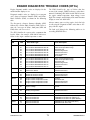
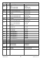
Engine Diagnostic Codes (EDC’s) . . . . . . . . . . . . . . . . . . . . . . . . . . . . . . . .71
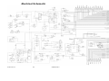
Electrical Schematics . . . . . . . . . . . . . . . . . . . . . . . . . . . . . . . . . . . . . . . . . .73
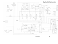
Hydraulic Schematics . . . . . . . . . . . . . . . . . . . . . . . . . . . . . . . . . . . . . . . . . .74
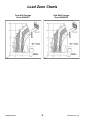
Load Zone Charts . . . . . . . . . . . . . . . . . . . . . . . . . . . . . . . . . . . . . . . . . . . . .75
Standard Hardware Torque Data . . . . . . . . . . . . . . . . . . . . . . . . . . . . . . . . .77
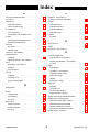
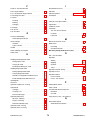
Index . . . . . . . . . . . . . . . . . . . . . . . . . . . . . . . . . . . . . . . . . . . . . . . . . . . . . . .78
Warranty . . . . . . . . . . . . . . . . . . . . . . . . . . . . . . . . . . . . . . .Inside Back Cover
PRINTED IN U.S.A.
1
50960067/BP0514
Chapter 1
INTRODUCTION
The information in this Operator’s Manual was written to give the owner/operator assistance in preparing, adjusting, maintaining and servicing of the Telescopic Handler. More important, this manual provides an operating plan
for safe and proper use of the machine. Major points of safe operation are detailed in the SAFETY chapter of this
manual.
Manitou Americas Inc. asks that you read and understand the contents of this manual
COMPLETELY and become familiar with the machine before operating it.
The use of this Telescopic Handler is subject to certain hazards that cannot be eliminated by mechanical means,
but only by the exercise of intelligence, care and common sense. It is therefore essential to have competent and
careful operators, who are not physically or mentally impaired, and who are thoroughly trained in the safe operation of the equipment and the handling of the loads.
Throughout this manual information is provided that is set in italic type and introduced by the word IMPORTANT
or NOTE. Be sure to read carefully and comply with the message or directive given. Following this information
will improve operating and maintenance efficiency, help to avoid breakdowns and damage, and extend the
machine’s life. A chart of standard hardware torques is located in the back of this manual.
A storage pocket in the back of the seat is provided for storing the Operator’s Manual. After using the manual,
please return it to the pocket and keep it with the unit at all times! If this machine is resold, this manual should be
given to the new owner.
If this machine was purchased “used,” or if the owner’s address has changed, please provide your Manitou
Americas Inc. dealer or Manitou Americas Inc. Service Department with the owner’s name and current address,
along with the machine model and serial number. This will allow the registered owner information to be updated,
so that the owner can be notified directly in case of an important product issue, such as a safety update program.
“Right” and “left” are determined from a position sitting on the seat and facing forward.
The wide Manitou Americas Inc. dealership network stands ready to provide any assistance that may be required,
including genuine Manitou Americas Inc. service parts. All parts should be obtained from or ordered through your
Manitou Americas Inc. dealer. Give complete information about the part, and include the model and serial number
of the machine. Record the serial number in the space provided on the previous page, as a handy record for quick
reference.
Please be aware that Manitou Americas Inc. reserves the right to make changes or improvements in the design or
construction of any part without incurring the obligation to install such changes on any unit previously delivered.
Manitou Americas Inc., in cooperation with the Society of Automotive
Engineers, has adopted this
Safety Alert Symbol
to identify potential safety hazards, which, if not properly avoided, could
result in injury. When you see this symbol in this manual or on the
machine itself, you are reminded to BE ALERT! Your personal safety is
involved!
50960067/BP0514
2
PRINTED IN U.S.A.
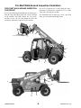
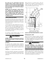
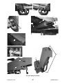
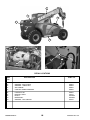
Identification
Telescopic Boom
Dash Indicators
and Controls
Slave Cylinder
Tilt Cylinder
Quick-attach
System
Operator’s Station
Seat
Auxilluary
Hydraulics
Extend Cylinder
Inside Boom
Rear Boom
Access Cover
Lift Cylinder
Exhaust Pipe
Rear View
Mirror
Fuel Tank
Behind Access
Cover
Air Cleaner
under Engine
Cover
PRINTED IN U.S.A.
3
Hydraulic Tank
Filler under
Engine Cover
50960067/BP0514
Chapter 2
SPECIFICATIONS
Lifting Performance
Steering System
Axles (front and rear)
Maximum lift capacity:
5500 lbs. (2495 kg)
Steer Valve: Fixed-displacement rotary
Displacement/Rev: 7.3 cu. in. (120 cc)
System pressure: 2400 psi (165 bar)
Steer cylinders: 1 per axle
Steer mode valve:
3-position, 4-way solenoid with
dash-mounted switch actuation
Steer modes: 2-wheel, 4-wheel, crab
Front Axle: Dana model 60-211-69
Braking System
Natural Aspiration Yanmar 4TNV98
202 cu. in. (3.32 liters) displacement
69.3 hp (50.7 kW) @ 2500 rpm
173 ft.-lbs. (235 Nm)
torque @ 1625 rpm
Oil capacity: 9.5 qts. (9.0 L)
Features:
In-line 4-cycle, 4-cylinder, directinjection diesel fuel system, in-line
5 micron fuel pre-filter with water
trap, and in-line 1 micron primary
fuel filter, positive pressure lubrication, liquid pressurized cooling
system, 19” (483 mm) suction fan,
dry dual-element air cleaner,
spin-on oil filter.
Maximum lift height:
19’ 1”(5.8 m)
Capacity at maximum lift height:
3000 lbs. (1361 kg)
Max. forward reach to load center:
11’ (3.35 m)
Capacity at maximum forward reach:
1850 lbs. (840 kg)
Maximum below grade reach:
0” (0 mm)
General Dimensions
Based on standard machine equipped
with listed tires, 48” masonry carriage
and 48” pallet forks.
Recommended tire type:
12 - 16.5 NHS 10-ply
Overall length, less forks:
148” (3.76 m)
Overall width:
71” (1.80 m)
Service brakes: Oil-immersed inboard
hydraulic wet-disc type; front axle
Manual foot pedal actuation
Parking brake: Spring-applied, hydraulicrelease disc-type in front axle
Actuation is electric switch with engine
running, automatic with engine off.
Electrical System
Type: 12-volt, negative ground
Battery: 950 minimum cold cranking
amps
Circuit protection: Fuse panel
Backup alarm: 107 dB(A)
Horn: 111 dB(A)
Alternator: 95 amp
Drive/steer, limited-slip differential,
full-time four-wheel drive
Rear Axle: Dana model 221-83
Drive/steer, open differential,
full-time four-wheel drive
Engine
Hydraulic System
Type: Open-center
Pump: Single-section gear type
Overall height:
76” (1.93 m)
Service Capacities
Ground clearance: 10.5” (266 mm)
Wheelbase: 90” (2.29 m)
Outside turn radius: 132” (3.35 m)
Cooling System: 12 qts. (11.3 L)
50/50 mixture
Anti-freeze protection: -31oF (-35oC)
Pressure cap: 14 psi (1.0 bar)
Displacement / revolution:
2.20 cu. in. (36 cc)
Fuel tank: 17 gals. (64 L)
Hydraulic tank:
18 gals. (68 L)
Axles:
Differentials: 4 qts. (3.8 L) ea.
Planetaries:
Front: 27 oz. (0.8 L) ea.
Rear: 30 oz. (0.9 L) ea.
Transfer Case (front axle only):
8 oz. (0.23 liters)
Main relief pressure:
3350 psi (231 bar)
Steer relief pressure:
2400 psi (166 bar)
Machine weight without attachment:
9,760 lbs. (4400 kg)
Instrumentation
Gauges: Fuel level, hourmeter,
coolant temperature, Voltmeter, Engine
speed
Monitoring lights:
Engine oil pressure, alternator,
hydrostatic drive oil temperature,
engine coolant temperature, air cleaner,
low fuel, hydraulic filter, engine failure
and glow indicator.
Visual indicators:
Boom angle, frame angle
Hydrostatic Transmission
Hydraulic filter:
Return type, 16-micron
media, replaceable element.
Rated flow: 35 gpm (132 L/min)
Rated pressure: 1000 psi (70 bar)
By-pass pressure (full flow):
50 psi (345 kPa)
Type: Rexroth A4VG56DA/32
Speeds: 2 fwd / 2 rev
Travel Speeds:
Low speed:
High speed:
50960067/BP0514
Flow @ 2530 RPM:
22 gpm (83 L/min)
fwd/rev 4 mph (6.4
km/h)
fwd/rev 15 mph (24
km/h)
4
PRINTED IN U.S.A.
Chapter 3
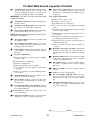
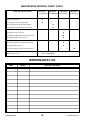
CHECKLISTS
I acknowledge that the pre-delivery procedures were performed on this unit as outlined above.
PRE-DELIVERY
The following Checklist is an important reminder of inspections that MUST be made before delivering the Telescopic
Handler to the customer. Check off each item after the prescribed action is taken.
Dealership’s Name
√ Check that:
q NO parts of machine have been damaged in shipment.
q
q
q
q
q
q
q
q
q
q
Dealer Representative’s Name
Date Checklist Filled Out
Check for such things as dents and loose or missing parts;
correct or replace components as required.
Battery is securely mounted and not cracked. Cable connections are tight. Electrolyte at proper level.
Cylinders, hoses and fittings are not damaged, leaking or
loosely secured.
Oil, fuel and air filters are not damaged, leaking or loosely
secured.
All grease fittings have been properly lubricated and no fittings are missing; see Lubrication chapter of this manual.
Wheel nuts are torqued to 450 ft.-lbs. (610 Nm).
Tires are inflated to 65 psi (448 kPa) cold.
Hydraulic system reservoir, engine crankcase, engine
coolant, transmission and axles are filled to the proper
operating fluid levels.
All adjustments have been made to comply with the settings given in this manual and in the separate engine manual.
All guards, shields and decals are in place and securely
attached.
Model and serial numbers for this unit are recorded in
space provided on this page and page 1.
Machine Model #
q
q
Engine Serial #
DELIVERY
√ Check that:
The following Checklist is an important reminder of valuable information that MUST be passed on to the customer at
the time the unit is delivered. Check off each item as you
explain it to the customer.
q Review with the customer the contents of this manual and
the AEM Safety Manual and for the following:
q The Index at the back, for quickly locating topics;
q The Safety, Indicators and Controls, and Operation and
Adjustments chapters for information regarding safe use of
the machine.
q The Lubrication, Service and Storage, and Maintenance
chapters for information regarding proper maintenance of
the machine. Explain that regular lubrication and maintenance are required for continued safe operation and long
life.
q Give this Operator’s Manual and the AEM Safety Manual
Start the machine and test-run the unit while
checking that proper operation is exhibited by all
controls.
√
q
q
q
Machine Serial #
q
Check that:
to the customer and instruct them to be sure to read and
completely understand their contents BEFORE operating
the unit.
Remind the customer of U.S. OSHA regulation 1910.178
(l), which specifies operator training requirements.
q Explain that the customer must consult the engine manual
All indicators (lamps, switches, etc.) function properly.
All hand and foot controls operate properly.
Boom, Quick-attach System with attachment tool all function properly.
No hydraulic system leaks when under pressure.
Listen for abnormal noises or vibrations; if detected, determine their cause and repair as necessary.
q
(provided) for related specifications, operating adjustments
and maintenance instructions.
Completely fill out the Owner’s Registration, including
customer’s signature, and return it to the Company.
Customer’s Signature
Date Delivered
(Dealer’s File Copy - Remove at Perforation)
PRINTED IN U.S.A.
5
50960067/BP0514
INTENTIONALLY BLANK
(To be removed as Dealer’s file copy)
50960067/BP0514
6
PRINTED IN U.S.A.
Chapter 3
CHECKLISTS
I acknowledge that the pre-delivery procedures were performed on this unit as outlined above.
PRE-DELIVERY
The following Checklist is an important reminder of inspections that MUST be made before delivering the Telescopic
Handler to the customer. Check off each item after the prescribed action is taken.
Dealership’s Name
√ Check that:
q NO parts of machine have been damaged in shipment.
q
q
q
q
q
q
q
q
q
q
Dealer Representative’s Name
Date Checklist Filled Out
Check for such things as dents and loose or missing parts;
correct or replace components as required.
Battery is securely mounted and not cracked. Cable connections are tight. Electrolyte at proper level.
Cylinders, hoses and fittings are not damaged, leaking or
loosely secured.
Oil, fuel and air filters are not damaged, leaking or loosely
secured.
All grease fittings have been properly lubricated and no fittings are missing; see Lubrication chapter of this manual.
Wheel nuts are torqued to 450 ft.-lbs. (610 Nm).
Tires are inflated to 65 psi (448 kPa) cold.
Hydraulic system reservoir, engine crankcase, engine
coolant, transmission and axles are filled to the proper
operating fluid levels.
All adjustments have been made to comply with the settings given in this manual and in the separate engine manual.
All guards, shields and decals are in place and securely
attached.
Model and serial numbers for this unit are recorded in
space provided on this page and page 1.
Machine Model #
q
q
Engine Serial #
DELIVERY
√ Check that:
The following Checklist is an important reminder of valuable information that MUST be passed on to the customer at
the time the unit is delivered. Check off each item as you
explain it to the customer.
q Review with the customer the contents of this manual and
the AEM Safety Manual and for the following:
q The Index at the back, for quickly locating topics;
q The Safety, Indicators and Controls, and Operation and
Adjustments chapters for information regarding safe use of
the machine.
q The Lubrication, Service and Storage, and Maintenance
chapters for information regarding proper maintenance of
the machine. Explain that regular lubrication and maintenance are required for continued safe operation and long
life.
q Give this Operator’s Manual and the AEM Safety Manual
Start the machine and test-run the unit while
checking that proper operation is exhibited by all
controls.
√
q
q
q
Machine Serial #
q
Check that:
to the customer and instruct them to be sure to read and
completely understand their contents BEFORE operating
the unit.
Remind the customer of U.S. OSHA regulation 1910.178
(l), which specifies operator training requirements.
q Explain that the customer must consult the engine manual
All indicators (lamps, switches, etc.) function properly.
All hand and foot controls operate properly.
Boom, Quick-attach System with attachment tool all function properly.
No hydraulic system leaks when under pressure.
Listen for abnormal noises or vibrations; if detected, determine their cause and repair as necessary.
q
(provided) for related specifications, operating adjustments
and maintenance instructions.
Completely fill out the Owner’s Registration, including
customer’s signature, and return it to the Company.
Customer’s Signature
Date Delivered
(Pages 5 and 6 have been removed at perforation)
PRINTED IN U.S.A.
7
50960067/BP0514
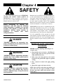
Chapter 4
SAFETY
The above Safety Alert Symbol means ATTENTION!
ALWAYS BE ALERT! YOUR SAFETY IS
INVOLVED! It stresses an attitude of safety awareness and can be found throughout this Operator’s
Manual and on the machine itself.
Manitou Americas ALWAYS takes the operator’s safety into consideration when designing its machinery,
and guards exposed moving parts for his/her protection. However, some areas cannot be guarded in order
to assure proper operation. Further, this Operator’s
Manual and decals on the machine warn of additional
hazards and should be read and observed closely.
Before
attempting
to
operate
this
equipment, read and study the following
safety information. In addition, be sure that
everyone who operates or works with this
equipment, whether family member or
employee,
is
familiar
with
these
safety precautions.
REMEMBER! It is the owner’s responsibility for communicating information on the safe use and proper
maintenance of this machine! This includes providing
understandable interpretations of these instructions
for operators who are not fluent in reading English.
It is the responsibility of the operator to read and
understand the Operator’s Manual and other information provided and use the correct operating procedure.
Machines should be operated only by qualified operators.
DANGER
“DANGER” indicates an imminently hazardous situation that, if not avoided, will result
in death or serious injury.
MANDATORY SAFETY SHUTDOWN
PROCEDURE
BEFORE cleaning, adjusting, lubricating or servicing the unit:
WARNING
1. Stop machine on a level surface. (AVOID parking on a slope, but if necessary, park across the
slope and block the tires.)
“WARNING” indicates a potentially hazardous
situation that, if not avoided, could result in
death or serious injury.
2. Fully retract the boom and lower the attachment tool to the ground. Idle engine for gradual
cooling.
3. Place controls in neutral and apply parking
brake.
CAUTION
4. Shut off the engine and remove the key.
ONLY when you have taken these precautions can
you be sure it is safe to proceed. Failure to follow
the above procedure could lead to death or serious
bodily injury.
“CAUTION” indicates a potentially hazardous
situation that, if not avoided, may result in
minor or moderate injury. It may also alert to
unsafe practices.
50960067/BP0514
8
PRINTED IN U.S.A.
SAFETY
Additional Safety Reminders
WARNING
Ü User/operator safety practices, as established by
industry standards, are included in this Operator’s
Manual and intended to promote safe operation of
the machine. These guidelines do not preclude the
use of good judgment, care and common sense as
may be indicated by the particular jobsite work
conditions.
U.S. OSHA regulations require employers in
general industry and the construction, shipyard and cargo-handling industries (excepting
agricultural operations) to ensure that forklift
operators are competent, as demonstrated by
successful completion of a training course.
Ü It is essential that operators be physically and mentally fit, free of mind-altering drugs and chemicals,
and thoroughly trained in the safe operation of the
machine. Such training should be presented completely to all new operators and not condensed for
those claiming previous experience. Information
on operator training is available from several
sources, including the manufacturer.
The training course must consist of a combination of formal instruction and practical
training, including both forklift-related and
workplace-related topics, and evaluation of
the operator’s performance in the workplace.
All operator training and evaluation is to be
conducted by persons who have the knowledge, training and experience to train and
evaluate operators.
Ü Some illustrations used in this manual may show
doors, guards and shields open or removed for
illustration purposes ONLY. BE SURE that all
doors, guards and shields are in their proper operating positions before starting the engine.
Before Operation Safety Reminders
Ü
WARNING
ALWAYS maintain a safe distance from electric power lines and avoid contact with any
electrically charged conductor or gas line. It is
not necessary to make direct contact with a
power line for power to ground through the
structure of the machine. Keep the boom at
least 10 ft. (3 m) from all power lines.
Accidental contact or rupture can result in
electrocution or an explosion. Contact the
North American One-Call Referral System at
(888) 258-0808 for the local “Digger’s Hotline”
number or proper local authorities for utility
line locations before starting to dig!
Perform a pre-start walk-around inspection before
starting the engine at the beginning of each work
shift. Contact with a running engine or moving
parts during the pre-start inspection could cause
death or serious injury. Refer to the pre-start
walk-around inspection checklist in the
“Operation and Adjustment” chapter.
Ü Walk around the machine and warn all personnel
who may be servicing the machine or who are in
the machine path prior to starting. DO NOT start
until all personnel are clearly away from the
machine.
Ü Check brakes, steering, and hydraulic system prior
to starting operation. Operate all controls to ensure
proper operation. Observe all gauges and indicators for proper operation. If any malfunctions are
found, correct the cause prior to using the machine.
Ü ALWAYS wear appropriate personal protective
equipment for the job and working conditions.
Hard hats, goggles, protective shoes, gloves,
PRINTED IN U.S.A.
9
50960067/BP0514
SAFETY
reflector-type vests, respirators and ear protection
are exampes of types of equipment that may be
required. DO NOT wear loose fitting clothing,
long hair, jewelry or loose personal items while
operating or servicing the machine.
Ü Study the load chart carefully. It shows maximum
capacity to be lifted and placed at specific outward
and upward distances. ALWAYS be aware of load
weights prior to attempting lift and placement with
this machine.
Ü ALWAYS check the job site for terrain hazards,
obstructions and people. Remove all objects that
do not belong in or on the machine and its equipment.
Ü DO NOT exceed the machine’s rated operating
capacity for the type of attachment tool being used.
Ü DO NOT allow minors or any unqualified personnel to operate or be near the machine unless properly supervised.
Operation Safety Reminders
Ü DO NOT start the engine or operate any controls
unless properly seated in the operator’s seat!
Ü Any or all of the following elements may affect the
stability of the machine: terrain, engine speed, type
of load being carried and placed, improper tire
inflation, weight of the attachment tool, and abrupt
movement of any control lever. IF YOU ARE
NOT CAREFUL WHILE OPERATING THIS
MACHINE, ANY OF THE ABOVE FACTORS
COULD CAUSE THE MACHINE TO TIP
AND THROW YOU OUT OF THE OPERATOR’S STATION, WHICH MAY CAUSE
SERIOUS BODILY INJURY OR DEATH!
Ü DO NOT run the engine in an enclosed area without providing proper ventilation for the exhaust.
Exhaust gases contain carbon monoxide, an odorless and deadly gas. Internal combustion engines
deplete the oxygen supply within enclosed spaces
and may create a serious hazard unless the oxygen
is replaced. This includes the atmosphere within
the cab when equipped.
Ü DO NOT leave the operator’s station with the
boom and attachment tool raised. ALWAYS lower
the boom and attachment tool to the ground, shut
off the engine and engage the parking brake
BEFORE leaving the operator’s station.
Ü ALWAYS wear the seat belt provided to prevent
being thrown from the machine. If you are in an
overturn:
- DO NOT jump!
- Hold on tight and stay with the machine!
- Lean away from the fall!
Ü ALWAYS keep hands, feet and arms inside of the
operator’s station when operating the machine!
Ü
NEVER travel with the boom above the carry
position (attachment tool should be at minimum
ground clearance.) Boom should be fully retracted.
Ü DO NOT depend on the backup alarm to clear
bystanders out of the path of the machine. Always
look in the direction of travel. Look to the rear
before backing.
Ü DO NOT drive too close to an excavation or ditch.
BE SURE that the surrounding ground has adequate strength to support the weight of the machine
and the load it is carrying.
Ü ALWAYS use the recommended hand holds and
steps with at least three points of support when getting on and off the machine. Keep steps and platform clean. Face the machine when climbing up
and down.
Ü DO NOT turn quickly while traveling on a slope or
operate the machine beyond the grade and slope
limits noted in the Operation and Adjustments
chapter of the Operator’s Manual.
Ü NEVER allow any riders on this machine or use as
a lift for personnel. This is strictly a single-seat,
NO passenger machine!
Ü DO NOT raise or drop a loaded fork or bucket suddenly. Abrupt movements under load can cause
serious instability.
50960067/BP0514
10
PRINTED IN U.S.A.
SAFETY
Ü When road travel is required, know and use the
signaling devices on the machine. Provide an
escort and Slow-Moving Vehicle (SMV) emblem
when required.
3. Work zone ground conditions can support
the equipment and load. Any hazardous
conditions in the work area have been
identified, and the operator notified.
Ü If necessary to park on a slope, park across the
slope and block the tires.
4. Equipment is being used within its rated
capacity and in accordance with the manufacturer's instructions.
Suspended Load Safety Reminders
5. Operator and crew members have been
trained in the safe use and operation of the
equipment, including how to avoid electrocution.
The handling of suspended loads by means of a truss
boom, winch, boom mounted lift hook or other similar
device can introduce dynamic forces affecting the stability of the machine that are not considered in the stability criteria of industry test standards. Grades and
sudden starts, stops and turns can cause the load to
swing and create a hazard. Refer to the following
guidelines for handling suspended loads.
6. During use, no part of the equipment, load
line or load will be within the minimum
clearance distance specified by OSHA [10
feet (3.0 m), and more for lines rated over
50 kV] of any energized power line, and
any taglines used are non-conductive.
WARNING
7. In addition, for lift equipment with a rated
capacity greater than 2000 lbs. (907 kg),
the employer must ensure that:
U.S. OSHA regulations effective November 8,
2010 (29 CFR Part 1926, Subpart CC - Cranes
and Derricks in Construction) include requirements for employers that use powered industrial trucks ("forklifts") configured to hoist (by
means of a winch or hook) and move suspended loads horizontally. In particular, this
regulation applies to any rough-terrain forklift
(e.g., "telescopic handler") equipped with a jib
or truss boom with a hook (with or without a
winch), or a hook assembly attached to the
forks. [Note: This regulation is in addition to
the OSHA regulation that requires specific
forklift operator training: §1910.178(l).]
a.) An accessible fire extinguisher is on
the forklift;
b.) Monthly and annual inspections are
performed and documented, and
records retained (three months for
monthly, one year for annual);
c.) Before November 10, 2014, operators
must have had the additional training
and qualification / certification required
by OSHA regulations §1926.1427 and
§1926.1430.
When a forklift / telescopic handler is configured and used for hoisting, the employer must
ensure that:
Note: Refer to the full text of the OSHA crane
regulation (29 CFR Part 1926, Subpart CC) for
a detailed description of the regulatory
requirements.
1. Forklift, lift equipment and rigging have
been inspected (each shift, month and
year) and are in good, safe condition and
properly installed.
Ü
2. An operator's manual and applicable load
charts are on the forklift.
PRINTED IN U.S.A.
11
DO NOT exceed the rated capacity of the telescopic handler as equipped for handling suspended loads. The weight of the rigging must be
included as part of the load.
50960067/BP0514
SAFETY
Ü
During transport, the length of the rigging
between the attachment and load should be as
short as possible to reduce booms height and
movement. DO NOT raise the load more than 12
inches (305 mm) above the ground, or raise the
boom more than 45 degrees.
Ü
Only lift the load vertically – NEVER drag it horizontally.
Ü
Use multiple pickup points on the load when possible. Use taglines to restrain the load from
swinging and rotating.
Ü
Start, travel, turn and stop SLOWLY to prevent
the load from swinging. DO NOT exceed walking
speed.
Ü
Ü NEVER use your hands to search for hydraulic
fluid leaks. Instead use a piece of paper or cardboard. Escaping fluid under pressure can be invisible and can penetrate the skin, causing serious
injury. If any fluid is injected into your skin, see a
doctor at once. Injected fluid MUST be surgically
removed by a doctor familiar with this type of
injury or gangrene may result.
Ü ALWAYS wear safety glasses with side shields
when striking metal against metal. In addition, it is
also recommended that a softer (chip-resistant)
material be used to cushion the blow. Failure to
heed could lead to serious injury to the eyes or
other parts of the body.
Ü DO NOT refill the fuel tank when the engine is
hot. Allow engine to cool down before refilling to
prevent hot engine parts from igniting the fuel if it
should spill or splash.
Inspect rigging before use. Rigging must be in
good condition and in the U.S. comply with
OSHA regulation §1910.184, “Slings,” or
§1926.251, “Rigging equipment for material handling.”
Ü
Rigging equipment attached to the forks must be
secured such that it cannot move either sideways
or fore and aft. The load center must not exceed
24 inches (610 mm).
Ü
DO NOT lift the load with anyone on the load,
rigging or lift equipment, and NEVER lift the
load over personnel.
Ü
Beware of the wind, which can cause suspended
loads to swing, even with taglines.
Ü
DO NOT attempt to use frame-leveling to compensate for load swing.
Ü DO NOT smoke while filling the fuel tank, working on the fuel or hydraulic systems, or working
around the battery.
Ü DO NOT fill the fuel tank completely. Allow room
for expansion. Maintain control of the fuel filler
nozzle when filling the tank. Use the correct fuel
grade for the operating season.
Ü Static electricity can produce dangerous sparks at
the fuel-filling nozzle. Do not wear polyester, or
polyester-blend clothing while fueling. Before
fueling, touch the metal surface of the machine
away from the fuel fill to dissipate any built-up static electricity. Do not re-enter the machine but stay
near the fuel filling point during refueling to minimize the build-up of static electricity. Do not use
cell phones while fueling. Make sure the static line
is connected from the machine to the fuel truck
before fueling begins.
Servicing Safety Reminders
Ü ALWAYS be aware of and avoid pinch-point areas
on the machine, such as wheels-to-frame, cylinders-to-frame, boom- and attachment-tool-toframe.
Ü Ultra-Low Sulfur Diesel (ULSD) poses a greater
static ignition hazard than earlier diesel formulations. Avoid death or serious injury from fire or
explosion; consult with your fuel or fuel system
supplier to ensure the entire fuel delivery system is
in compliance with fueling standards for proper
grounding and bonding practices.
Ü NEVER attempt to by-pass the keyswitch to start
the engine. ONLY use the jump-starting procedure
detailed in the Service and Storage chapter.
Ü NEVER use fuel for cleaning purposes.
50960067/BP0514
12
PRINTED IN U.S.A.
SAFETY
Ü DO NOT remove the radiator cap after the engine
has reached operating temperature or if it is overheated. At operating temperatures, the engine
coolant will be extremely hot and under pressure.
ALWAYS wait for the engine to cool before
attempting to relieve pressure and remove the radiator cap. Failure to heed this warning could result
in severe burns.
Safety Guards and Warning Devices
Ü This machine is fitted with a Roll-Over Protective
Structure (ROPS) and Falling Object Protective
Structure (FOPS) in accordance with industry standards. The structure is intended to offer protection
to the operator in case of an overturn and from
falling objects, but it cannot protect against every
possible hazard. Therefore it should not be considered a substitute for good judgment and safe practices in operating the machine. If the ROPS / FOPS
structure is damaged, it must be replaced to restore
the protection it provides.
Ü DO NOT loosen or disconnect any hydraulic lines,
hoses or fittings without first relieving hydraulic
circuit pressure. Also, be careful not to touch any
hydraulic components that have been in recent
operation because they can be extremely hot and
can burn you!
Ü This machine is equipped with a horn and backup
alarm. The user must determine if operating conditions require the machine to be equipped with
additional devices (mirrors, rotating beacon, etc.)
and be responsible for providing and maintaining
such devices.
Ü Avoid lubrication or mechanical adjustments with
the machine in motion or the engine running. If the
engine must be running to make certain adjustments, place the equipment in a safe position,
place the transmission in neutral, apply the parking
brake, securely block the wheels and use extreme
caution.
Ü To ensure continued safe operation, replace damaged or worn-out parts with genuine Manitou
Americas service parts before using this equipment.
Modifications, Nameplates, Markings and
Capacities
Ü Modifications and additions that affect capacity or
safe operation must never be performed without
the manufacturer’s prior written approval. Where
such authorization is granted, any applicable markings are to be changed accordingly.
Ü All attachment tools MUST be marked to identify
the attachment tool and the total capacity with the
attachment tool at maximum elevation with the
load laterally centered.
Ü ALWAYS be sure all nameplates, warnings and
instruction markings are in place and legible.
Local government regulations may require specific decals, which are the responsibility of the owner
to provide.
PRINTED IN U.S.A.
13
50960067/BP0514
SAFETY
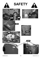
808033
808033
808031
809291
808038
808054
808036
808033
808034
50960067/BP0514
14
PRINTED IN U.S.A.
SAFETY
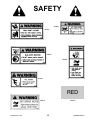
808054
808033
808034
808036
808031
RED
809291
PRINTED IN U.S.A.
808038
15
50960067/BP0514
SAFETY
808037
808029
808027
808030
808032
808031
808035
808027
808031
808029
808035
808032
808037
808030
50960067/BP0514
16
PRINTED IN U.S.A.
Chapter 5
INDICATORS AND CONTROLS
GUARDS AND SHIELDS
CAUTION
Whenever possible and without affecting machine
operation, guards and shields are used to protect potentially hazardous areas. In many places, decals are also
provided to warn of potential hazards and to display
special operating procedures.
Before operating the Telescopic Handler,
become familiar with and know how to use
ALL safety devices and controls. Know how to
stop the machine operation before operating
it. This Manitou America machine is designed
and intended to be used ONLY with a Manitou
America attachment tool, or a Manitou
America approved accessory or referral
attachment tool. Manitou America cannot be
responsible for safety if the machine is used
with an unapproved accessory or attachment
tool.
Steering Wheel
WARNING
Read and thoroughly understand all safety
decals on the Telescopic Handler before operating it. DO NOT operate the machine unless
all factory-installed guards and shields are
properly secured in place.
Frame Angle
Indicator
Instrument and
Switch Panel
Boom Angle
Indicator
Travel Direction
Lever
Horn Button
Attachment / Auxiliary
Hydraulics Joystick
Key Switch
Start Button
Boom Control
Joystick
Brake Pedal
Throttle Pedal
Arm Rest
Operator’s Compartment and Indicators/Controls Locations
PRINTED IN U.S.A.
17
50960067/BP0514
Load Zone Charts: A
set of flip charts show
lift height and reach limits relative to the load
weight being handled
with various attachment
tools.
DASH PANEL AREA
A
B
C
D
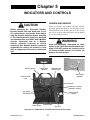
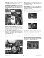
INSTRUMENT AND SWITCH PANEL
Located to the right of the steering wheel, this panel
contains the instrument gauges, indicator lamps and
function switches.
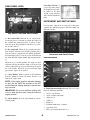
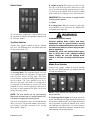
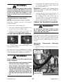
Key Switch, Start and Horn Buttons
A - Key switch OFF: When the key is vertical in the
keyswitch, power is disconnected from the battery to
the control and instrument panel electrical circuits.
Also, this is the only position in which the key can be
inserted or removed.
B - Key switch ON: When the key is turned one position clockwise from the vertical (OFF) position, power
from the battery is supplied to all controls and multifunction display panel electrical circuits. Indicators on
the multi-function display should light up momentarily.
Instrument and Switch Panel
Instrumentation
When the key is in this position, the engine pre-heat
indicator will stay on until the engine is pre-heated. In
colder temperatures the pre-heat indicator will stay lit
for 3-30 seconds. When the pre-heat indicator light
goes out the engine can be started.
C
H
D
I
E
J
C - Start Button: With keyswitch in ON position,
press the button to activate the starter. Release it as
soon as the engine starts.
B
F
K
G
NOTE: If the engine requires repeated attempts
to start, the key MUST be returned to the OFF
position between starting attempts to prevent battery run down.
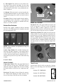
A - Multi-Function Display Screen: This screen displays the following functions:
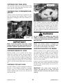
IMPORTANT: Do not use additional starting aids
such as ether injection when using the electrical
engine preheat.
D - Horn Button: Press the horn button to activate
warning sound.
50960067/BP0514
A
18
•
•
•
•
•
•
•
fuel level at all times,
engine coolant temperature,
engine speed,
voltmeter
hourmeter
250 hour maintenance reminder
error fault codes
•
DPF regeneration status and level
PRINTED IN U.S.A.
B - Scroll Button: Pressing this button changes the
function displayed in the multi-function display
screen.
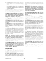
lamp should be off. During starting and when the ignition is on but the engine is not running, this lamp will
be on.
Press and hold the button in for 3 seconds to toggle the engine coolant tmperature reading between
celsius and fahrenheit.
IMPORTANT: If this lamp comes on during normal operation, stop the engine immediately! After
allowing the oil to drain down for a few minutes,
check the engine oil level. Maintain oil level at the
FULL mark on the dipstick.
A1 - Fuel Level Gauge: The fuel level is displayed at
all times in the lower portion of the display. It indicates
the amount of fuel remaining in the fuel tank.
E - Engine Coolant Temperature Lamp: This lamp
indicates when the temperature of the engine coolant is
too high.
A2 - Engine Coolant Temperature: Press button “B”
until “TEMP” is displayed. It indicates the temperature
of the engine coolant. Under normal conditions, this
should indicate approximately 185°F (85°C).
IMPORTANT: If this lamp comes on during normal operation with the engine running, STOP the
engine as soon as possible and check the engine
cooling system.
A3 - Engine Speed: Press button “B” until “RPM” is
displayed. This indicates the engine speed.
A4 - Voltmeter: Press button “B” until “VOLTS” is
displayed. This indicates the voltage output from the
alternator.
F - Alternator Lamp: This lamp indicates the condition of the electrical charging system. During normal
operation, this lamp should be off. If the charge rate is
too high or too low, this lamp will come on.
A5 - Hourmeter: Press button “B” until “HRS” is displayed. It indicates the total operating time of the
machine and should be used for keeping the maintenance log.
G - Air Cleaner Restriction Indicator Lamp: If this
lamp comes on, the engine air filter requires service.
H - Engine Pre-heat Indicator Lamp: When lighted
this lamp indicates that the cold weather starting aid is
in use.
A6 - Maintenance Reminder: After every 250 hours
a reminder will display: “ROUTINE MAINTENACE
IS REQUIRED ⎯ CHECK OPERATOR’S MANUAL.” Perform the required maintenance, and then clear
the message by pressing and holding button “B” until
the message is cleared.
I - Hydrostatic Transmission Oil Temperature
Lamp: This lamp indicates when the temperature of
the transmission oil is too high. During normal operation this lamp should be off, indicating that the transmission oil system is at the proper temperature.
NOTE: The maintenance reminder message
must display at least three minutes before it can
be cleared by pressing and holding button “B”.
IMPORTANT: If this lamp comes on during normal operation, a problem may exist in the transmission oil system. Stop the machine immediately and investigate the cause of the problem!
A7 - Error Fault Code: Error codes and a short error
description are displayed in this screen. The error code
will clear when the error is corrected.
J - Low Fuel Lamp: This lamp indicates a low fuel
situation. The fuel tank should be filled as soon as possible.
A8 - DPF Regeneration: If the auto regen has been
disabled or an auto regen is in process, a message will
be displayed indicating the need for a DPF regeneration along with the level of regeneration needed as
“LOW”, “MEDIUM” OR “HIGH”.
K - Hydraulic Oil Filter Restriction Lamp: If this
lamp comes on, the hydraulic oil filter requires service.
Indicator Lamps
C - Engine Failure: This lamp when lit, alerts the
operator of a fault condition. Refer to the multi-function display screen for error codes.
D - Engine Oil Pressure Lamp: This lamp indicates
when the engine lubricating oil pressure is too low.
During normal operation, with the engine running, this
PRINTED IN U.S.A.
19
50960067/BP0514
When this indicator is illuminated, the machine
can be operated as normal unless the operator
determines the machine is not in a safe location
for high exhaust temperatures and disables auto
cleaning.
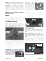
Exhaust Filter Gauge Indicators and
Switches
B1
B2
A3
B3
B4
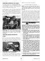
B2 - Auto Cleaning Disabled Indicator: This
indicator will illuminate when the operator has
disabled the auto exhaust filter cleaning function
from the exhaust filter cleaning switch (A). This
icon will remain illuminated until the operator reengages automatic exhaust cleaning from the
exhaust filter cleaning switch (A). Disabling the
auto mode is not recommended for any situation
unless it is safety related or if the fuel tank lacks
the recommended 1/4 tank of fuel to complete the
cleaning process.
A1
A2
A - Exhaust Filter Cleaning Switch: This switch controls the function of the exhaust filter. It has 3 positions
as follows:
B3 - Exhaust Filter Indicator: This indicator
will illuminate when the exhaust filter is in need
of cleaning because the soot level of the exhaust
filter is slightly high and the operator has disabled
auto exhaust filter cleaning. If conditions are safe,
the operator should enable the auto exhaust filter
clean setting or perform manual exhaust filter
cleaning.
A1 Center position: In this position the exhaust filter cleaning procedure is set to the automatic
(AUTO) mode. Operating the engine in this center AUTO Mode allows the ECU to perform intelligent exhaust filter cleaning as required.
A2 Bottom position: In this position the auto exhaust
filter cleaning is disabled.
A3 Top position: In this position the operator initiates a manual exhaust filter cleaning operation.
This process allows the system to clean the
exhaust filter when the operator previously disabled exhaust filter cleaning by pressing the bottom of the switch. The top of the switch will need
to be pressed for at least three seconds, and the
park brake engaged to activate. The indicator in
the switch will illuminate when activated and be
off when the exhaust filter cleaning is complete.
B4 - Exhaust Filter Warning Indicator: This
amber or red indicator works in combination with
the Exhaust Filter Indicator (B3).
•
B - Exhaust Filter Gauge: This gauge displays the
four indicators you will see through the operator initiated or auto exhaust filter cleaning and disable
processes.
•
NOTE: The indicators in the exhaust filter gauge
will all illuminate when the keyswitch is put in the
“ON” position for a momentary lamp check.
During normal operation all lamps will never all be
illuminated at the same time. This image is only to
illustrate the indicators you may see during operation.
•
B1 - Exhaust Filter Cleaning Indicator: This
indicator will illuminate when exhaust gas temperature is at optimal regeneration temperature,
elevated idle is active, or exhaust filter cleaning is
in process.
50960067/BP0514
20
If this indicator is illuminated amber when the
Exhaust Filter Indicator (B3) is illuminated, the
engine performance will be reduced by the ECU
because the soot level of the exhaust filter is moderately high. If conditions are safe, the operator
should enable the auto exhaust filter clean function. If conditions are not safe, the operator should
move the machine to a safe location and engage
the auto exhaust filter cleaning mode.
If this indicator is illuminated red when the
Exhaust Filter Indicator (B3) is illuminated, the
engine performance will be further reduced by the
ECU because the soot level of the exhaust filter is
extremely high. This combination will lead to a
“Service Only” soot condition, contact your authorized Manitou Americas dealer.
This indicator will also illuminate red when an
engine fail condition exists. Refer to the multifunction screen for error code information.
PRINTED IN U.S.A.
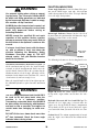
B - High/Low Speed: This switch is used to select the
travel speed. Press the top of the switch to select low
speed, used for load pickup and placement, or whenever low speed operation is desired. Press the bottom
of the switch to select high speed, used for road travel.
Switch Panel
IMPORTANT: Be sure machine is stopped before
changing travel speeds.
C - Blank
D - Parking Brake: When the machine is parked, this
switch should be pressed to actuate the parking brake
mechanism in the front axle.
WARNING
The switch panel contains three rows of switches for
the operation of standard and optional equipment on
the telescopic handler.
Unattended machine hazard.
Activate parking brake switch and lower
attachment tool to ground before leaving
machine. An unattended machine can move or
roll and cause death or serious injury to operator or bystanders.
Top Row Switches
Switches have graphic symbols to indicate function
and effect. The following mode descriptions start with
the first switch on the left.
Periodically check the parking brake operation to verify that it has adequate holding
power. Always be sure the parking brake
switch is off when resuming machine operation.
Middle Row Switches
A
B
C
Switches have graphic symbols to indicate function
and effect. The following mode descriptions start with
the first switch on the left.
D
A - Steering Mode: This 3-position switch is used to
select among the three steering modes. The upper position selects the 4-wheel steering mode. This mode
selects all-wheel steering for making tighter turns, usually on a jobsite. The center position selects the 2wheel steering mode. This mode selects front wheel
steering only, used for higher speed travel. The lower
position selects the crab steering mode. This mode is
used when a small amount of side shift is needed for
picking or placing a load.
E
G
H
NOTE: Some switches are optional and may not
be on machine.
NOTE: The rear wheels are not self-centering.
Make sure all wheels are in a straight-ahead position before changing the steering mode.
E - Head Lights/Work Lights: Pressing the top of the
switch will illuminate the lights mounted on the top of
the operator’s station and the red tail lights for forward
travel operations. Pressing the bottom of the switch
will illuminate the lights at the end of the boom in
addition to the lights on the operator’s station for additional lighting in working operations.
Any of the steering modes can be used in both forward
and reverse travel. The operator should learn to anticipate changes in machine movement if the steering
mode must be changed.
PRINTED IN U.S.A.
F
21
50960067/BP0514
F - Turn Signal: This switch is used to indicate the
direction of a turn with the tail lights. Press the right
arrow for a right turn; press the left arrow for a left
turn. Return the switch to the center position after the
turn is completed.
G - Hazard: This switch can be activated to make the
tail lights flash on and off in case the machine is stalled
or temporarily stopped in a traffic area on the road or
jobsite.
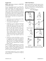
Temperature
Control Knob
H - Strobe: When a beacon is installed on the machine,
activating this switch will produce a strobe-light on
and off flashing, for working in conditions that may
obscure view of the machine.
Fan Speed Knob
Heater A/C Controls
Fan Speed: This is the upper knob located to the left
of the steering wheel. The fan is in the off position
when the knob is rotated completely to the left.
Rotating the knob clockwise will switch the fan on and
increase the fan speed for increased air circulation.
Bottom Row Switches
Switches have graphic symbols to indicate function
and effect. The following mode descriptions start with
the first switch on the left.
I
J
K
Temperature Control: This knob is located below the
fan speed knob. It is used to adjust the temperature output of the heater A/C unit. Turning the knob clockwise
from the midpoint position will increase the temperature output of the cab heater. Turning the knob counterclockwise from the midpoint position will switch the
A/C unit on and decrease the temperature output of the
cab A/C.
L
Fan Speed
Knob
NOTE: Some switches are optional and may not
be on machine.
I and J - Wiper/Washer: The windshield and top window of the operator’s station are each equipped with a
wiper and washer mechanism. The left switch (I) operates the wiper and washer on the windshield; the second switch (J) operates the wiper and washer on the top
window.
Temperature
Control Knob
K and L - Blank
Heater Controls
Travel Lever
Temperature Control: This is the upper knob located
to the left of the steering wheel. This knob is used to
adjust the temperature output of the cab heater. Turning
the knob clockwise will increase the temperature output.
Located on the left side of the steering wheel column,
this lever is used to change travel direction (forward or
reverse).
Position “F” (FORWARD)
Fan Speed: This knob is located below the temperature control knob. Rotating the knob clockwise will
increase the fan speed for increased air circulation.
50960067/BP0514
Position “N” (NEUTRAL)
Position “R” (REVERSE)
22
PRINTED IN U.S.A.
NOTE: The lever MUST be in N (Neutral) position
before the starter will engage to start the engine.
Suspension Seat (optionA
al): In addition to the “A”
latch handle for forward and
B
rearward adjustment, this
seat has a knob “B” under
the front of the seat to adjust
the suspension. Turn the
knob to the right for a softer ride, and to the left for a
firmer ride.
IMPORTANT: Care should be taken when changing direction, because damage to the hydrostatic
transmission can occur if shifting is forced or
attempted at too high a speed. Allow machine
speed to slow before any directional change is
attempted.
NOTE: Backup alarm automatically sounds with
travel lever in reverse.
Seat Belt: This machine has a retractable seat belt.
Grasp the belt on the left side of the seat pulling the
belt over your lap and inserting the belt into the buckle on the right side of the seat until you hear it lock in
place.
Steering
The power steering system is designed to provide loweffort steering without shock reaction from the axle
wheels to the steering wheel. Turn the steering wheel
to the right or left to turn the machine in that direction.
Seat Belt
FLOOR AND SEAT AREA
Throttle Pedal: This is right-foot operated and controls the engine speed to match increased power
requirements. Pushing down on the pedal increases the
RPM; letting up on the pedal decreases RPM.
RIGHT SIDE PANEL
Brake Pedal
These controls are used to position the boom and
attachment. Graphic symbols indicate the control
actions.
Throttle Pedal
Boom Control Joystick: This machine has a
hydraulic-type telescopic boom. The boom section
extends by means of a hydraulic cylinder inside the
boom.
To extend the boom, move the joystick handle to the
right; to retract the boom, move the joystick handle to
the left. To raise the boom, move the joystick handle
rearward; to lower the boom, move the joystick handle
forward.
Service Brake Pedal and Transmission Cut-off:
Pressing the brake pedal hydraulically activates the
internal braking mechanism in the front axle. During
initial brake pedal travel and as the brake pedal is
pressed farther, power to the transmission is progressively cut off. This allows faster engine speeds at slower operating speeds while maintaining power to the
hydraulic system.
Boom Control
Joystick
Seat Positioning: The seat is mounted on rails for forward and rearward repositioning to accommodate the
operator’s size. A springA
loaded latch handle under
the front of the seat activates
the adjustment mechanism.
PRINTED IN U.S.A.
Auxiliary Hydraulics and
Attachment Tilt Joystick
23
50960067/BP0514
FUNCTION INDICATORS
WARNING
Frame Angle Indicator: Located in front of the operator on the ROPS upper cross tube, this indicator
enables the operator to check if the Telescopic Handler
is at a safe angle for operation.
Use extreme caution when raising or extending the boom. The Telescopic Handler MUST
be within safe lifting parameters as indicated
by the frame angle indicator. Loaded or empty,
this machine can tip if not level.
ALWAYS place the transmission in neutral, set
the parking brake and keep the service brake
pedal fully depressed before raising or
extending the boom.
Boom Angle Indicator: Mounted on the left side of
the outer boom, the position of the ball shows the angle
of boom elevation relative to the ground.
NEVER exceed the specified lift and reach
capacities of this machine. Serious machine
damage or personal injury may result. Refer to
the load charts in the operator’s station or this
manual.
If a boom circuit hose bursts with the boom
up, with or without a load, shut down the
machine following the Mandatory Safety
Shutdown Procedure (page 8). DO NOT
attempt repairs. Call your Manitou America
dealer for assistance.
Boom Angle
Indicator
SERVICE AND SAFETY FEATURES
The following indicators are for checking fluid levels.
Coolant
Expansion Tank
Attachment Tilt/Auxiliary Hydraulics Joystick: To
tilt the attachment tool up, move the joystick handle
rearward; to tilt the attachment tool down, move the
joystick handle forward. When the operator tilts the
attachment tool to a desired angle, that angle will be
maintained as the boom is raised and lowered, extended and retracted, until a new angle is set.
Engine Oil
Dipstick
Move the joystick handle to the left or right to operate
the additional hydraulics required on some attachment
tools.
Hydraulic Oil
Sight Gauge
WARNING
Engine Oil Level: The yellow dipstick is located on
the top of the engine about centered above the valve
cover.
The truss boom attachment tool should ONLY
be used to lift and place loads when the
machine is in a stationary position.
Transporting suspended loads must ALWAYS
be done slowly and cautiously, with the boom
and load as low as possible. Use taglines to
restrict loads from swinging, to avoid overturn.
Hydraulic Reservoir Oil Level and Fill Cap: The
hydraulic oil level sight gauge is located under the
engine cover directly below the battery compartment.
The hydraulic oil fill cap is located under the engine
cover toward the front, just to the left of the air cleaner.
DO NOT tilt the truss boom back more than
45o from horizontal. Check the frame angle
indicator before raising a load.
50960067/BP0514
Hydraulic Oil
Fill Cap
Coolant Level: The coolant expansion tank is located
under the engine cover forward of the radiator on the
backwall.
24
PRINTED IN U.S.A.
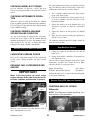
Brake Fluid Reservoir: Located in the front of the
frame on the inside left wall under the cover.
Battery: The battery is located under the engine cover
toward the front of the engine compartment directly to
the rear of the air cleaner.
Windshield Washer Fluid Reservoir: Located under
the cover on the front of the frame. The fluid level is
visible through the reservoir or by removing the reservoir cap.
Backup Alarm: Located under the frame above the
rear axle; it produces a loud warning sound whenever
the machine is in reverse.
Right Side Rear View Mirror: Located on the right
side of the machine; it provides the operator a view of
the area on the right side and behind the machine.
Brake Fluid
Reservoir
Windshield Washer
Fluid Reservoir
Right Side Rear View Mirror
Left Side Rear View Mirror (optional): Located on
the left side of the cab; it provides the operator a view
of the area on the left side and behind the machine.
Hydraulic Restriction Indicator: This indicator is
located on the multi-function display in the operator’s
compartment. (Refer to Checking and Changing
Hydraulic Return Filter Element, page 56.)
Left Side Rear View Mirror
Cab Right Side Window or Panel: Located on the
right side of the cab; this window or panel protects the
operator from coming in contact with the boom.
Air Filter Restriction Indicator: This indicator is
located on the multi-function display in the operator’s
compartment. (Refer to Checking and Changing Air
Filter Element, page 56.)
Cab Rear Window: Located on the rear of the cab;
this window protects the operator from material flying
off the rear wheel.
Hydraulic Pressure Test Port: Located off the lower
portion of the battery compartment; a gauge can be
attached to this port to check main valve and steering
pressures
Operator Station Fuse and Relay Compartment:
Located under the hinged load chart panel; lift the front
of the panel to access the fuses and relays.
Battery
Main Valve and
Steering Pressure
Test Port
PRINTED IN U.S.A.
25
50960067/BP0514
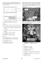
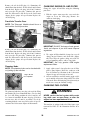
Operator Station Fuse and Relay Functions: Refer
to the illustration and following description for the fuse
and relay functions.
Engine Compartment Fuses, Relays and Solenoids:
Located inside the engine compartment on the firewall.
Turn the quater-turn latch to lift the panel from the firewall. Lay the panel on top of the engine to access the
fuses and relays.
Fuse/Relay
Panel
Quarter-Turn
Latch
Engine Compartment Fuses and Relay Functions:
Refer to the illustration and following description for
the fuse and relay functions.
FUSES:
F1. 15 AMP Fuse: ignition switch, horn, brake lights
F2. 20 AMP Fuse: transmission, neutral start, park
brake, steer mode, fuel pump, backup alarm, air
intake fan
C
D
F3. 15 AMP Fuse: lights, turn signals, hi/low speed,
hazard
F4. 25 AMP Fuse: gauges, heater/hvac
F5. 25 AMP Fuse: top wiper motor
A
F6. 25 AMP Fuse: front wiper motor
B
RELAYS:
R1. 20/40 AMP Change-over Relay: ignition
R2. 20/40 AMP Change-over Relay: park brake
R3. 20 AMP Relay: lights
R4. 20 AMP Relay: top wiper
8
R5. 20 AMP Relay: front wiper
7
6
5
4
3
2
1
FUSES:
1. 80 AMP Fuse: Alternator
2. 80 AMP Fuse: Glow Plug
3. 60 AMP Fuse: Chassis Power
4. 60 AMP Fuse: Starter
5. 40 AMP Fuse: A/C Evaporator (when equipped)
6. 30 AMP Fuse: A/C Condenser (when equipped)
7. 20 AMP Fuse: EGR
8. 20 AMP Fuse: ECU
50960067/BP0514
26
PRINTED IN U.S.A.
SOLENOIDS:
A. Starter
B. Glow Plug
RELAYS:
C. 20 AMP Relay: Regen Interlock
D. 20 AMP Relay: EGR Valve
ATTACHMENT TOOLS
Manitou America offers a versatile range of attachment
tools to meet various lifting and material handling
applications. Contact your Manitou America dealer for
specifications and ordering information.
ACCESSORIES
Manitou America offers a range of special accessories
for this machine. Contact your Manitou America dealer for specifications and ordering information.
NOTE: All accessories are field-installed unless
otherwise noted. Information and parts for
installing accessories are provided by the Manitou
Americas or Manitou Americas Telescopic
Handler dealers.
PRINTED IN U.S.A.
27
50960067/BP0514
INTENTIONALLY BLANK
50960067/BP0514
28
PRINTED IN U.S.A.
Chapter 6
OPERATION AND ADJUSTMENTS
GENERAL INFORMATION
PRE-START WALK-AROUND INSPECTION
CAUTION
It is the operator’s responsibility to perform a pre-start
inspect of the machine before the start of each workday. Every pre-start inspection must include more than
simply checking the fuel and oil levels. It is a good
practice to personally inspect any machine you are
assigned to use, even though it has already been put
into service by other personnel.
BEFORE starting the engine and operating the
Telescopic Handler, review and comply with
ALL safety recommendations in the Safety
chapter of this manual. Know how to STOP the
machine before starting it. Also, BE SURE to
fasten and properly adjust the seatbelt.
The pre-start inspection is designed to discover if the
machine has incurred any damage or is in need of routine service.
ENGINE BREAK-IN
A new engine does not require extensive “break-in.”
However, for the first 100 hours of operation, follow
these guidelines: Allow the engine to idle for a few
minutes after every cold start. DO NOT idle the engine
for long periods of time. DO NOT operate the engine
at maximum power for long periods of time. Check the
oil level frequently and replenish as necessary with the
oil specified in the engine manual.
Any needed repairs are to be made by a qualified service technician.
Refer to the illustration and checklist on the next two
pages for the “Pre-Start Walk-Around Inspection.”
Yanmar engines do not use a “break-in” oil. After the
first 50 hours of operation, change the oil and replace
the oil filter. Consult the Lubrication chapter for the
type and grade of oil to use. Refer to the Service and
Storage chapter for the proper service intervals.
PRINTED IN U.S.A.
29
50960067/BP0514
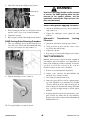
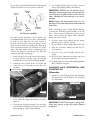
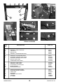
Pre-Start Walk-Around Inspection Illustration
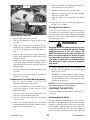
Any needed repairs or service noted during the inspection must be performed by a qualified service technician before operating the machine.
PRE-START WALK-AROUND INSPECTION
PROCEDURE
Refer to the following illustration and checklist to perform the inspection. Begin with item 1 at the left front
of the machine and walk toward the rear of the
machine on the left side and around the back and
toward the front on the right side of the machine.
The illustration and checklist page can be copied for
future pre-start walk-around inspections.
3
1
4
5
2
13
12
11
10
6
8
7
9
21
18
16 17
14
14
22
19
20
14
50960067/BP0514
15
30
PRINTED IN U.S.A.
Pre-Start Walk-Around Inspection Checklist
o1.
Attachment Tool: Check for broken missing or damaged parts. When utilizing forks, check for welds,
cracks or misalignment. Replace the forks in sets
when the condition of the fork(s) is questionable.
o14. Covers, Doors and Latches: All covers doors and
latches are in working condition; properly secured
with no loose or missing parts; all components operate properly.
IMPORTANT: DO NOT use forks that have been
repaired by welding.
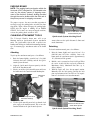
o15. Engine Compartment:
o Engine oil level, add if needed.
o Coolant level, add if needed.
o Hydraulic oil level, add if needed.
o No evidence of engine oil, hydraulic oil or coolant
leaks.
o Hydraulic Cooler and Radiator: No loose or missing
parts; no visible damage.
o Belts and hoses in good condition, properly secured
and adjusted.
o Exhaust System: No loose or missing parts; no visible damage; no obstructions to the outlet.
o Engine Air Cleaner: No loose or missing parts; no
obstructions to the inlet.
o Battery: No loose or broken cables; no damage or
corrosion.
o16. Hydraulic Control Valve Assembly: (located under
the boom on side of operator station) No loose or
missing parts; not leaking; no damaged or leaking
hoses.
o2.
Attachment Tool Mount: No loose or missing parts;
no visible damage.
o3.
Attachment Tool Mounting Pins: No visible damage; pin fit is secure and properly lubricated.
o4.
Boom Section and Wear Pads: No loose or missing
parts; no visible damage; no excessive wear.
NOTE: Wear pads that measure 3/8” (9.5 mm) thick or
less need to be replaced.
o5.
Boom Angle Indicator: Looseness; no visible damage; bubble is visible.
o6.
Tire and Wheel Assemblies: Properly secured; no
loose or missing lug nuts; no visible damage (cuts or
abrasions); proper tire inflation.
o7.
Front and Rear Axles: No loose or missing parts; no
visible damage; tie rod end studs locked; properly
lubricated.
o8.
Operator Compartment:
o Seat belt undamaged; operates properly; mounting
hardware secure.
o Switches and levers undamage;
o no loose or missing parts;
o load charts properly secured and legible;
o levers and switches operate properly; control markings legible;
o frame level indicator secured and undamaged, bubble is visible.
o9. Boom Hydraulic Hoses: No visible damage or exterior wear; no evidence of leaking.
o17. Hydraulic Oil Reservoir: (located under the boom
in the center of the frame) No evidence of leaking;
breather cap working and secure.
o18. Lift Cylinder: Properly secured; no visible damage;
no evidence of leaking from the cylinder; properly
lubricated.
o19. Mirror Assembly: No visible damage; adjusted
properly.
o20. Frame: No cracks or visible damage.
o21. Tilt and Auxiliary Hydraulic Hoses: (Auxiliary
hoses are optional and not shown on this machine)
No damage or excessive wear; no evidence of leaking.
o10. Slave Cylinder: Properly secured; no visible damage; no evidence of leaking from the cylinder; properly lubricated.
o22. Attachment Tilt Cylinder: Properly secured; no visible damage; no evidence of leaking from the cylinder; properly lubricated.
o11. Rear Light Assemblies (when equipped): Properly
secured; no visible damage; no loose or disconnected
wires; function properly.
o12. Fuel Tank: No damage or leaking; breather cap
secure and working.
o13. Boom Pivot Assembly: Properly secured; no visible
damage or excessive wear; properly lubricated.
Date: _________________Initials: _______________
PRINTED IN U.S.A.
31
50960067/BP0514
5. Press the start button. Release the button as soon as
the engine starts. If the button is released before
the engine starts, turn the keyswitch to “OFF”
position and allow the starter to stop before
attempting to start again.
BEFORE STARTING ENGINE
Before mounting the operator’s compartment, walk
completely around the machine to be sure no one is
under, on, or close to it. Let others in the area know
you are going to start up and wait until everyone is
clear of the machine.
IMPORTANT: Crank the starter until the engine
starts. If the engine fails to start within 15 seconds, return the key to the “OFF” position, wait at
least 30 seconds, and try again to start the
engine. Cranking the engine for longer than 15
seconds will result in premature failure of the
starter.
Before starting the engine and running the machine,
refer to the Indicators and Controls chapter and
become familiar with the various operating controls,
indicators and safety features.
STARTING THE ENGINE
6. After the engine starts, allow a sufficient warm-up
time before operating the controls.
The following procedure is recommended for starting
the engine:
7. Check that indicators are in normal condition.
1. Grasp the hand holds to step up into the operator’s
compartment.
8. Check that there are no fuel, oil or engine coolant
leaks, and no abnormal noises or vibrations.
2. Adjust the seat and fasten the seat belt.
COLD STARTING
A optional block heater is recommended for starting in
temperatures of 20oF (-7oC) or lower.
WARNING
The block heater should be connected to an AC power
supply several hours prior to starting the engine
depending on the ambient temperature.
ALWAYS fasten your seat belt before starting
the engine. Leave the parking brake applied
until the engine is running and you are ready
to operate the machine.
WARNING
3. Check that all controls are in their “neutral” positions, except the parking brake switch, which
should be in the “ON” position.
Do not use starting fluid (ether) with engine
preheat systems. An explosion can result,
which can cause engine damage, injury or
death.
WARNING
Do not use starting fluid (ether) with engine
preheat systems. An explosion can result,
which can cause engine damage, injury or
death.
If the battery becomes discharged and does not have
sufficient power to start the engine, jumper cables can
be used for starting assistance. Refer to the jump starting instructions in the Service and Storage chapter of
this manual for safe jump starting procedures.
4. Turn the key switch to “ON” position. The preheat indicator on the multi-function display will be
“ON” indicating the pre-heater is in use. When the
indicator goes out, the engine can be started.
STOPPING
The following procedure is the recommended
sequence for stopping the machine:
1. Bring the machine to a stop on a level surface.
Avoid parking on a slope, but if necessary, park
across the slope and block the tires.
NOTE: The engine pre-heater is used to assist
starting in cold weather conditions. The indicator
may stay lighted for 3-30 seconds depending on
the temperature. If you are operating the telescopic handler in normal or warm weather conditions, the pre-heat indicator will go out in several
seconds and you can start the engine.
50960067/BP0514
2. Fully retract the boom and lower the attachment to
the ground. Idle the engine for 5 minutes to allow
engine components to cool slightly before shutting
the engine down.
32
PRINTED IN U.S.A.
3. Place controls in neutral. Apply the parking brake.
4.
4. Turn the ignition switch key to the “OFF” position.
Remove the key.
Use only ultra low sulfur diesel (ULSD) fuel. See
Lubrication chapter of this maual or the engine
manual for fuel requirements.
FIRST TIME OPERATION
Even with proper maintenance, ash and soot will build
up in the exhaust filter after several thousand hours of
operation and require service. This service will need to
be performed by a authorized Manitou dealer.
Make sure the engine is warm and then go through the
following procedures:
Automatic (AUTO) Exhaust Filter Cleaning
5. Unfasten the seatbelt, and grasp the hand holds
while climbing out of the operator’s compartment.
Be sure the area used for test-running is clear
of spectators and obstructions. Initially, operate the machine with an empty attachment
tool.
Operating the engine in AUTO Mode allows the ECU
to perform intelligent exhaust cleaning as required.
The Exhaust Filter Cleaning Indicator will illuminate
when the system is actively performing an exhaust filter cleaning. When the exhaust filter cleaning process
has completed its cycle, the cleaning indicator will turn
off.
Select the travel direction. Switch off the parking brake
and move ahead slowly, while testing the steering and
brakes. Stop and operate all boom and attachment tool
function controls, checking for smooth response.
The machine can be operated as normal during the auto
exhaust filter cleaning process unless the operator
determines the machine is not in a safe location for
high exhaust temperatures and disables the auto cleaning process.
CAUTION
To enable the auto exhaust filter cleaning mode, the
exhaust filter cleaning rocker switch should be in the
center position.
Apply the service brakes, stop the machine and move
the travel lever to the opposite direction.
IMPORTANT: To prevent damage to the transmission, the Telescopic Handler should be traveling at a slow speed and not accelerating when
changing the direction of travel.
IMPORTANT: It is recommended that the exhaust
filter cleaning be in the Auto mode at all times.
Auto mode should only be disabled when the
machine is not in a safe location during the
exhaust filter cleaning process.
EXHAUST FILTER CLEANING SYSTEM
The engine is equipped with an exhaust filter in place
of a muffler. This filter is located to the front of the
engine under the engine cover. This exhaust filter
reduces carbon monoxide, hydrocarbons, and particulate matter from the exhaust stream. Trapped particles
are eventually oxidized through a process known as
regeneration or exhaust filter cleaning.
If the machine is not able to be moved to a safe location, the operator should temporarily disable auto
exhaust filter cleaning. If the machine is located in a
safe location, the auto mode should always be enabled.
Under normal machine operation and with the system
in AUTO mode, the exhaust filter requires minimal
operator interaction.
During auto or manual exhaust filter cleaning
operations, the engine will run at elevated idle
and hot temperatures for approximately 30
minutes. Exhaust gases and exhaust filter
components reach temperatures hot enough
to burn people, ignite, or melt common materials.
WARNING
To avoid unnecessary buildup of diesel particles or
soot in the exhaust filter system;
1.
Utilize the Automatic (AUTO) Exhaust Filter
Cleaning mode.
2.
Avoid unnecessary idling.
3.
Use the proper engine oil. See Lubrication chapter of this manual or the engine maual for proper
engine oil specifications.
PRINTED IN U.S.A.
Servicing the machine or attachments during
exhaust filter cleaning can result in serious
personal injury. Avoid exposure and skin contact with hot exhaust gases and components.
33
50960067/BP0514
If the machine is not in a safe location for elevated temperatures, move the machine to a
safe location and check for adequate fuel level
before beginning the exhaust filter cleaning
process.
Disable Exhaust Filter Cleaning
Disabling the exhaust filter cleaning request is not recommended. Disable the automatic exhaust filter cleaning only when necessary. Whenever possible, cleaning
should be allowed and the exhaust filter cleaning
switch should be left in the AUTO Mode. When left in
auto mode, soot buildup in the exhaust filter system
will be at a minimum.
Manual/Parked Exhaust Filter Cleaning
Manual/Parked exhaust filter cleaning is initiated by
the operator. This process allows the system to clean
the exhaust filter when the operator previously needed
to disable the auto exhaust cleaning process because of
specific conditions. During this process the engine
speed will be controlled by the ECU. The machine
must remain parked during this process.
To disable exhaust filter cleaning, press the bottom of
the exhaust filter cleaning rocker switch. The Auto
Cleaning Disabled Indicator located in the exhaust filter gauge will be illuminated.
Exhaust Filter Cleaning Precautions
NOTE: It is not necessary to perform a
manual/parked exhaust cleaning unless a previous auto cleaning process was cancelled and the
indicator in the exhaust filter gauge is illuminated.
When the AUTO Exhaust Filter Cleaning is disabled,
the sytem has 3 levels of notification to advise the
operator to perform the exhaust filter cleaning. The 3
levels are as follows;
Cleaning times will vary depending upon several specific criteria. The average standard cleaning time can
range from 20 - 50 minutes or longer.
1.
The Exhaust Filter Indicator
will illuminate, indicating the
the soot level in the filter is
slightly high. If conditions
are safe, the operator should
enable auto exhaust filter
cleaning or perform a manual
exhaust filter cleaning.
2.
The Exhaust Filter Indicator and
the Amber Alert Indicator in
the exhaust filter gauge will
illuminate. The engine per- Amber
formace will be reduced by
the ECU because the soot
level in the exhaust filter is
moderately high. If conditions are
safe, the operator should enable auto exhaust filter cleaning. If conditions are not safe, the operator should move the machine to a safe location
and either enable the auto exhaust filter cleaning
or perform a manual exhaust filter cleaning.
3.
The Exhaust Filter Indicator
and the Red Alert Indicator in
the exhaust filter gauge will
Red
illuminate. The ECU will
further reduce engine performance. Continuing to
operate the machine at this
level will set a “Service Only”
soot condition where the engine cannot clean the
exhaust filter itself. In this condition, contact your
authorized Manitou dealer.
To enable manual/parked exhaust filter cleaning;
1.
Park the machine in a safe location and check that
the machine has a recommended 1/4 tank of fuel
to complete the process.
2.
Reduce engine speed to low idle and apply the
parking brake.
3.
Press the top of the exhaust filter cleaning switch
for approximately 3 seconds until the indicator in
the switch illuminates. The cleaning indicator in
the exhaust filter gauge will also illuminate.
The indicators will go off when the exhaust filter
cleaning process is completed. If the machine is not
going to be returned to service immediately after the
cleaning process, allow the engine and the exhaust filter time to return to normal operating temperature
before stopping the engine. The manual/parked filter
cleaning process can be canceled at any time during the
process.
Avoid disabling the cleaning process unless absolutely
necessary. Repeated disabling or ignoring prompts to
perform a manual/parked cleaning procedure will
cause additional engine power limitations and can
eventually lead to dealer required service.
Utilize AUTO Exhaust Filter Cleaning mode to avoid
additional service.
50960067/BP0514
34
PRINTED IN U.S.A.
PARKING BRAKE
NOTE: The parking brake mechanism within the
front axle is NOT designed for, OR intended to be
used as, the primary means of stopping movement of the machine. Hydraulic braking provided
through the service brakes within the front axle is
the primary means for stopping movement.
The proper sequence for correct machine operation is
to always engage the parking brake switch before shutting off the engine; and to disengage the parking brake
ONLY after the engine is running. In an EMERGENCY, if it becomes necessary to stop the machine,
activate the parking brake switch to “ON.”
Attachment Tool Shown Locked
to Quick-attach System
CHANGING ATTACHMENT TOOLS
Quick-attach System Attaching Detail
The Telescopic Handler boom nose will accept
Manitou Americas Quick-attach System attachment
tools. The Quick-attach System has a quick-release
hookup and locking mechanism for mounting framingtype or masonry-type attachment tools to the boom
nose.
5. For an attachment tool with auxiliary hydraulics,
connect hoses to the quick-disconnect connectors
on the boom nose.
Attaching
1. Raise the boom slightly and extend it 2 to 3 feet
(600-900 mm) for better visibility. Lower the
boom until the attachment tool is approximately
12” (300 mm) off the ground.
Detaching
To detach attachment tool, proceed as follows:
To pick up the attachment tool, proceed as follows:
1. Raise the boom slightly, extend it 2 to 3 feet (600900 mm) for better visibility, and tilt the Quickattach System forward.
2. Roll the carrier rearward as far as it will go. When
the carrier is rolled all the way back, perform the
Mandatory Safety Shutdown Procedure (p. 8,
Safety chapter).
2. Align the Quick-attach System squarely with the
back of the attachment tool.
3. With the engine off, leave the operator’s station.
Manually raise the lock spring, and flip the lock
plate up and outward at least 180° so it is in position to re-lock on the next attachment tool.
3. Slowly extend the Quick-attach System and lower
the hooks under the attachment tool hookup bar.
Attachment
Tool
Quick-attach System Tilted
Forward for Hookup
Attachment Tool Shown
Unlocked for Release from
Quick-attach System
4. Tilt the Quick-attach System back so that the lock
plate engages the attachment tool. This secures the
attachment tool to the Quick-attach System.
Quick-attach System Detaching Detail
PRINTED IN U.S.A.
35
50960067/BP0514
4. Tilt the Quick-attach System forward to allow the
attachment tool to roll out, then lower the boom so
the hook ears clear the hookup bar on the attachment tool.
7. Check clearances of ramps, doorways and
passage-ways. Check overhead clearances if you
will travel and place loads near power or telephone
lines.
NOTE: One side of the lock plate has a bright red
decal to indicate the unlocked position.
WARNING
5. If the attachment tool has auxiliary hydraulics, disconnect the hoses from the quick-disconnects on
the boom nose.
Exhaust fumes can kill. Ensure proper ventilation when starting indoors or in enclosed
areas.
6. Start the engine and tilt the Quick-attach System
forward, then slowly back the machine until the
attachment tool is free from the boom nose.
Use proper hand holds, NOT the steering
wheel or control levers when mounting and
dismounting.
NEVER operate the machine with safety
guards or covers removed.
WARNING
Over-inflated tires can explode and cause
injury or death. Tire repairs MUST be made
only by authorized personnel using proper
tools and equipment.
Modifications, alterations to, or use of attachment tools not authorized by Manitou
Americas (or the manufacturer) in writing can
void warranty and cause machine damage
and/or serious personal injury or death.
If the machine is in need of repair or in any way unsafe,
or contributes to an unsafe condition, the matter must
be reported immediately to the user’s designated
authority. The machine must NOT be operated until it
has been restored to a safe operating condition.
SELF-LEVELING
The machine is equipped with a hydraulic self-leveling
feature. This feature is designed to keep the attachment
tool level while the boom is being raised and lowered.
Operate the travel controls gradually and smoothly
when starting, stopping, turning and reversing direction.
GENERAL MACHINE OPERATION
Check the Telescopic Handler to be sure all systems
are in good operating condition. Perform the following
steps before starting the machine the first time each
day:
Grade and Slope Precautions
The Telescopic Handler complies with industry stability test requirements and is stable when properly operated. However, improper operation, faulty maintenance, and poor housekeeping can contribute to a condition of instability and defeat the purpose of the standard.
1. Check the engine oil, coolant and hydraulic oil levels.
2. Check hydraulic oil cooler and engine radiator for
debris.
The amount of forward and rearward tilt to be used is
governed by the application. Although use of maximum rearward tilt is allowable under certain conditions, such as traveling with the load fully lowered, the
stability limits of the machine, as determined by the
industry standard tests, do not encompass consideration for excessive tilt at high elevations, or the handling of off-center loads.
3. Be sure weekly lubrication has been done.
4. Visually inspect for leaks and broken or malfunctioning parts. Be sure all caps, covers and safety
shields are in place.
5. Check tires for cuts, bulges, nails, correct pressure,
loose wheel nuts, etc.
6. Inspect the work area. Be sure you know where
you will make load pickups, lifts and turns. Look
over the terrain of the jobsite for holes, obstacles,
slippery surfaces, and soft or deep mud.
50960067/BP0514
Only handle loads within the capacity limits of the
machine, and which are stable and safely arranged.
When attachments are used, extra care should be taken
in securing, manipulating, positioning and transporting
the load.
36
PRINTED IN U.S.A.
Grade Limits
Traffic Flow Patterns
NOTE: Grade limits are based on ANSI/ITSDF
standard B56.6-2005.
Know and understand the traffic flow patterns of your
jobsite. Know all Telescopic Handler hand signals for
safety. Use signal persons as necessary for safe operation, and be sure you can see the signal person and
acknowledge the signals given.
This Telescopic Handler meets or exceeds the safety
standard (ANSI/ITSDF B56.6) stability limits for
rough terrain forklifts. The stability tipping limits
cover specific, controlled test conditions, which are
extremes, and which are not intended to be achieved
during normal worksite operations. The following
specifications are provided only as information to the
operator, and must not be used as a guideline for operating the Telescopic Handler. For safe operation,
always follow the instructions and warnings provided
in this manual.
Safety Hand Signals
1. DO NOT place or retrieve loads on an up or down
slope or grade that exceeds 7% or 4°.
2. DO NOT travel up or down a grade or slope that
exceeds 22% or 12° while loaded.
3. DO NOT place or retrieve loads on a side hill with
a slope or grade that exceeds 12% or 7°. Check the
location of the ball in the frame angle indicator
located on the ROPS/FOPS cross member. If the
ball in the frame angle indicator is in the green
zone, it is safe to place or retrieve the load. If the
ball in the frame angle indicator is in the yellow
zone, use slower movements and extra caution to
ensure remaining within the limits of the load
chart, because the machine is nearing an unstable
condition. If the ball in the frame angle indicator is
in the red zone, loads cannot be placed or
retrieved.
4. DO NOT travel across a side hill that exceeds 18%
or 10° grade. Check the frame angle indicator on
the ROPS/FOPS cross member to determine the
angle of the grade. The attachment tool MUST be
maintained at the “carry” position, with the boom
fully retracted and attachment tool at minimum
ground clearance.
When ascending or descending grades in excess of 5%
or 3°, the machine should be driven with the load
upgrade. An unloaded machine should be operated on
all grades with the load handling attachment tool
downgrade, tilted back if applicable, and raised only as
far as necessary to clear the ground surface.
Safety Hand Signals Continued on Next Page
Avoid turning if possible and use extreme caution on
grades, ramps and inclines. Normally travel straight up
and down the slope.
PRINTED IN U.S.A.
37
50960067/BP0514
IMPORTANT: DO NOT lower boom at high
engine speed when attachment tool is at maximum rearward tilt, because damage to slave
cylinders may result.
Safety Hand Signals Continued
GENERAL LOAD HANDLING
NEVER attempt to work controls except from the
operator’s seat. NEVER jerk or use fast movements.
Avoid sudden stops, starts and changes in direction.
Operation of the hydraulic system depends on engine
speed and the distance the controls are moved. When
operating these controls it is important to develop a
technique called “feathering.” Feathering the control
means starting the desired motion by moving the control a small amount away from neutral. Then after
movement has started, the control can be eased to full
movement. Use the same feathering technique to stop
the motion.
When ramps must be used in transporting loads with
the machine, the following are the minimum widths for
safe travel:
Compacted dirt, gravel, etc.
Woodboard, concrete, etc.
WARNING
12 ft. (3.6 m)
10 ft. (3.0 m)
Excessive speed can be hazardous. ALWAYS
exercise caution and good judgement while
operating the machine.
Permanent aisles, roadways and passageways, floors
and ramps must be clearly defined or marked.
Permanent or temporary protrusion of loads, equipment, material and construction facilities into the usual
operating area must be guarded, clearly and distinctively marked, or clearly visible.
ALWAYS maintain a safe distance from electric power lines and avoid contact with any
electrically charged conductor and gas line. It
is not necessary to make direct contact with a
power line for power to ground through the
structure of the machine. Keep the boom and
load at least 10 ft. (3 m) from all power lines.
Accidental contact or rupture can result in
electrocution or an explosion. Contact the
North American One-Call Referral System at
(888) 258-0808 for the local “Digger’s Hotline”
number or proper local authorities for utility
line locations BEFORE starting to dig!
Maintain a safe distance from the edge of ramps, platforms and other similar working surfaces.
Controlled lighting of adequate intensity should be
provided in operating areas. Where operating conditions indicate, the operator/user is responsible for having the machine equipped with lights.
Provisions must be made to prevent trucks, semi-trailers and railroad cars from being moved during loading
and unloading.
Keep all body parts inside the operator’s station while operating the machine. BE SURE of
clearance for the attachment tool when turning, working around buildings, etc.
Wheel stops, parking brakes, or other positive holding
means must be used to prevent movement during loading and unloading.
Turning corners too fast can tip the machine,
or cause a load to tip off the attachment.
Sudden slowing or stopping of the machine
may cause the load to drop off the attachment
tool.
DO NOT move railroad cars and trailers with the
Telescopic Handler.
DO NOT use the boom and attachment for leverage to
push the machine out of mud.
50960067/BP0514
38
PRINTED IN U.S.A.
During placement, the operator observes when the
extension reference number “2” on the boom becomes
visible and stops. The maximum safe distance of
extension with this load has been reached.
Be certain you can control both speed and
direction before moving. Always place the
machine in neutral and set the parking brake
before raising or extending the boom. NEVER
drive the machine up to someone standing in
front of the load.
BOOM
EXTENSION
MARKERS
HEIGHT ABOVE GROUND
NEVER leave the operator’s station without
first lowering the attachment tool to the
ground. Then set the parking brake, place controls in neutral, shut off engine and remove
the key. AVOID parking the machine on a
slope, but if necessary, park across the slope
and block the tires.
Load Capacity and Reach
This machine has flip-charts in the operator’s station
that provide the load capacity limits at various positions of attachment tool extension and elevation. A set
of the load zone charts is reproduced at the end of this
manual for reference.
A typical load zone chart is shown on the next page.
The scale on the left indicates height in feet above the
ground level. The scale on the bottom shows the distance in feet out from the front of the machine. The arc
lines noted by the numbers “1” through “4” correspond
to the position extension markers on the operator side
of the inner boom section.
DISTANCE LOAD IS EXTENDED
Typical Load Zone Chart
The following example illustrates proper use of the
load zone charts for the Telescopic Handler:
HANDLING NON-SUSPENDED LOADS
Picking Up the Load
WARNING
Inspect the load. If it appears unstable, DO NOT
attempt to move it. DO NOT attempt lifting doubletiered loads, or straddling side-by-side pallets with one
on each fork. NEVER add extra unauthorized counterweights to this machine.
NEVER exceed the rated operating capacity of
the Telescopic Handler as shown on the load
zone charts.
Example:
WARNING
The operator, using a standard carriage attachment
tool, wants to raise a 4000 pound load 10 feet high, and
can only get to within 5 feet of the load placement
point. Can it be done within the capacity of the
machine?
Operating conditions can reduce the
machine’s safe operating capacity. Exceeding
the capacity when raising or extending the
boom will cause the machine to tip forward.
Analysis: See “Typical Load Zone Chart” below.
Approach the load squarely and slowly with the
machine straight and level. Adjust the space between
forks, if necessary. Engage the load equally on both
forks until the load touches the carriage backrest. Tilt
the forks back to position the load for travel.
Projecting up from the 5-foot mark on the horizontal
axis to intersect a line through the 10-foot mark on the
vertical axis shows the load can be placed in the 4000
pound zone.
PRINTED IN U.S.A.
39
50960067/BP0514
Carrying the Load
WARNING
Be sure that the surrounding ground has adequate strength to support the weight of the
machine and the load it is carrying.
Always wear the seat belt provided to prevent
being thrown from the machine. If you are in
an overturn:
- DO NOT jump!
- Hold on tight and stay with the machine!
WARNING
- Lean away from the fall!
NEVER travel with the boom above the carry
position (attachment tool should be at minimum ground clearance). Boom should be fully
retracted.
2.
Set the parking brake, hold the service brake
pedal in fully applied position and slowly raise
the load, maintaining a slight rearward tilt to cradle the load.
NEVER coast with the transmission in neutral.
Travel up and down grades slowly.
3.
As the load approaches the desired height, feather the boom control at minimum speed until the
load is slightly higher than the landing point.
4.
Continue the feathering technique and lower the
load into place.
If the load obstructs your view, get someone to direct
you. Maintain ground speeds consistent with ground
conditions and which permit stopping in a safe manner.
5.
Free the forks from the load by alternately retracting and raising the boom. If this process is not
possible, very slowly and carefully reverse the
telescopic handler to free the forks from the load.
Elevating and Placing the Load
6.
Lower the forks to travel height.
DO NOT operate the machine on a slope or
grade that exceeds 22% or 12o.
For ground level load placement, be sure the area
under the load and around the machine is clear of
equipment and personnel. Lower the load to the
ground, tilt the forks to the horizontal position, and
then carefully back away to disengage forks from the
load.
WARNING
The machine becomes less stable as the load
is raised higher.
Before raising a load, be sure the Telescopic
Handler is within the safe lifting parameter as
indicated by the frame angle indicator.
For elevated or overhead placement, bring the machine
as close as possible to the landing point, and then:
If a hydraulic boom circuit hose should break
with the boom up, shut down the machine. DO
NOT attempt to bring down the boom or make
repairs. Call your Manitou Americas dealer
immediately.
WARNING
DO NOT raise the boom until you check the
frame angle indicator to verify that the ball is
in a safe zone for raising and placing a high
load.
1.
As lift height increases, depth perception
decreases. High elevation placement may
require a signal person to guide the operator.
Use extreme caution for high placement. Be sure
personnel are clear of the area where the load or
the machine could tip or fall.
50960067/BP0514
40
PRINTED IN U.S.A.
DO NOT ram the lift cylinder to the end of the
stroke. The resulting jolt could spill the load.
Carrying Suspended Load
A jib or truss boom should ONLY be used to
lift and place loads when the machine is stationary and the frame is level. Transporting
suspended loads must ALWAYS be done slowly and cautiously, with the boom and load as
low as possible. Use taglines to restrict loads
from swinging, to avoid overturns.
1.
Rigging between the load and attachment should
be as short as possible to reduce boom height.
2.
Do not raise the load more than 12 inches (305
mm) above the ground or raise the boom more
than 45 degrees.
3.
All telehandler movements should be performed
slowly and cautiously to prevent load swing.
Avoid abrupt movement. Do not exceed walking
speed.
4.
Use a signal person anytime the load restricts the
operators view or assistance is required. The signal person should remain in contact (verbally or
visually) with the operator at all times until the
load is placed.
HANDLING SUSPENDED LOADS
Determine the weight and load center of the load to be
handled. Refer to the telehandler load chart to determine if the load can safely be handled.
WARNING
NEVER exceed the rated operating capacity of
the telehandler as shown on the load zone
charts.
WARNING
Ground Level Suspended Load Placement
Operating conditions can reduce the telehandler’s safe operating capacity. Exceeding the
capacity when raising or extending the boom
will cause the telehandler to tip forward.
NOTE: Refer to the standard carriage load chart
when using the boom mounted hook.
1.
Be sure the area under the load and around the
telehandler is clear of equipment and personnel.
2.
Lower the load to the ground till load is stationary
and the rigging is loose from the load. Have signal person disconnect the rigging from the load.
3.
Raise boom enough to clear the rigging from the
load before backing the telehandler away from the
load.
Picking Up Suspended Load
1.
Rigging should be in good condition and rated for
the load being lifted.
2.
Rigging should comply with OSHA regulation
§1910.184, “Slings,” or §1926.251, “Rigging
equipment for material handling.”
3.
Be sure the rigging equipment is clear of any part
of the machine or machine attachment before lifting the load.
4.
Avoid lifting double-tiered or any unstable loads.
5.
Only lift loads vertically and clear from any adjcent obstacles. Never drag the load horizontally.
6.
Use multiple lift points and taglines to restrain the
load from swinging or rotating.
PRINTED IN U.S.A.
Elevated Suspended Load Placement
41
1.
Bring the telehandler as close as possible to the
landing point.
2.
Check the frame angle indicator to verify that the
ball is in the safe zone for placing a elevated load.
Use extreme caution for high placement. Be sure
personnel are clear of the load landing area.
3.
Set the parking brake, shift the transmission into
neutral, hold the service brake pedal fully applied
and slowly raise the load.
4.
As the load approaches the landing point, feather
the boom control at minimum speed until the load
is just above the landing point.
50960067/BP0514
5.
With the assistance of a signal person, continue
the feathering technique to lower the load into
place.
Loading Machine Using Ramps
NOTE: A matched pair of ramps is required.
WARNING
NEVER place the signal person between the
load and the telehandler or other stationary
objects.
6.
Once the load is stationary on the landing point
and the rigging is loose from the load, have the
signal person disconnect the rigging from the
load.
7.
Raise boom enough to clear the rigging from the
load. Slowly and carefully, reverse the telehandler
till the rigging is clear of the load.
8.
Ramp Placement
1. The ramps MUST be of sufficient strength to support the machine. Whenever possible, the use of
strong steel ramps is recommended as well as center supporting blocks.
Lower the boom to travel height.
ROAD TRAVEL
2. The ramps MUST be firmly attached to the truck
or trailer bed with NO step between the bed and
the ramps.
For short distance highway travel, attach a SlowMoving Vehicle (SMV) emblem (purchased locally) to
the rear of the Telescopic Handler. For highway operation, obtain and install an amber flashing beacon.
3. Incline of ramps MUST be less than 15 degrees.
Ramp length MUST be at least 16 feet (4.9 m)
long.
NOTE: ALWAYS follow ALL state and local regulations regarding the operation of equipment on or
across public highways. Whenever there is an
appreciable distance between jobsites, or if
driving on public highway is prohibited, transport
the machine using a vehicle of appropriate size
and capacity.
4. Ramp width MUST be at least 1-1/2 times the tire
width.
5. Block the front and rear of the tires on the truck or
trailer; engage the parking brake.
6. Position the machine with the boom facing toward
the front of the truck or trailer so that it is straight
in line with the ramps. Slowly (at the lowest engine
speed possible) and carefully drive the machine up
the ramps.
TRANSPORTING BETWEEN JOBSITES
ALWAYS abide by the following recommended procedures and guidelines when using ramps to load the
machine onto (and unload it from) a truck or trailer.
Failure to heed can result in damage to equipment and
serious personal injury or death!
7. Tie-down points are provided at the front and rear
corners of the frame structure.
WARNING
Tie-down points are provided for inserting chains to
secure the machine during transport.
Front Tie Down
50960067/BP0514
NEVER adjust travel direction (even slightly)
while on the ramps. Instead, back off the
ramps, and then realign the machine with the
ramps.
Rear Tie Down
42
PRINTED IN U.S.A.
1. Using suitable lift equipment, hook into the lift
eyes. Adjust the length of the slings or chains to lift
the telescopic handler level.
WARNING
NEVER transport the machine with the boom
raised or extended. BE SURE to secure the
machine (including boom) to the truck or trailer bed using chain and binders or steel
cables, to prevent any movement while transporting.
IMPORTANT: As needed, use a spreader bar to
prevent the slings or chains from rubbing the
sides of the boom.
2. Center the hoist over the Telescopic Handler. To
prevent shock loading of the equipment and excessive swinging of the load, slowly lift the
Telescopic Handler off the ground. Perform all
movements slowly and gradually. As needed, use a
tag line to help position the Telescopic Handler.
Unloading Machine Using Ramps
NOTE: A matched pair of ramps is required.
TOWING THE TELESCOPIC HANDLER
Repeat Steps 1 through 5 and proceed as follows to
unload the machine:
WARNING
6. Remove the tie-down chains/cables.
7. If necessary, adjust the machine so that the wheels
are in line and centered with the ramps.
Do not tow the Telescopic Handler at more
than 3 mph (5 km/h), and only for short distances (less than 100 yards).
8. Slowly (at the lowest engine speed possible) and
carefully drive the machine down the ramps.
LIFTING THE TELESCOPIC HANDLER
Front Lift Point
If the machine becomes disabled, it can be towed for a
short distance. To tow the Telescopic Handler, the high
pressure limiters on the hydrostatic transmission must
be unlocked and the SAHR parking brake must be
released.
Hydrostatic
Procedure
Rear Lift Point
The Telescopic Handler can be lifted using the four
lifting points shown above.
Transmission
Unlocking
1. Remove the plastic caps on the high pressure limiters.
Lift equipment used and its installation is the responsibility of the party conducting the lift. All rigging must
comply with applicable regulations and guidelines.
Upper High
Pressure Limiter
with Cap Removed
WARNING
Before lifting, check the lifting equipment for
proper installation.
-
Never allow riders in the operator’s station
while the telescopic handler is lifted.
-
Keep everyone a safe distance away from
the telescopic handler while it is lifted.
-
The telescopic handler may only be lifted
without a load on the forks, or without an
attachment. Never lift the telescopic handler with attachment other than those stated.
PRINTED IN U.S.A.
Lower High
Pressure Limiter
with Cap Removed
43
50960067/BP0514
2. Loosen the jam nut on a high pressure limiter.
WARNING
Release Screw
Before the Telescopic Handler can be returned
to service, the SAHR parking brake must be
returned to the applied position, and the
hydrostatic transmission high pressure limiters must be locked.
Jam Nut
SAHR Parking Brake Applying Procedure
1. Loosen the unlocking screws (1) and re-install the
stop washers (3).
3. While holding the jam nut, use an Allen wrench to
turn the center release screw in until it bottoms.
2. Tighten the unlocking screws against the stop
washers.
4. Tighten the jam nut.
5. Repeat steps 2-4 for the other high pressure limiter.
Hydrostatic
Procedure
SAHR Parking Brake Releasing Procedure
Transmission
Locking
1. Loosen the jam nut on a high pressure limiter.
1. There are unlocking screws on the front and rear
sides of the axle. Locate and loosen both unlocking
screws (1) and remove the stop washers (3).
2. Using an Allen wrench, turn the center release
screw back out until it stops.
3. Tighten the jam nut.
4. Repeat steps 1-3 for the other high pressure limiter.
THEFT DETERRENTS
Manitou Americas has recorded all major component
part numbers and serial numbers. Users should take as
many of the following actions as possible to discourage theft, to aid in the recovery in the event the
machine is stolen, and to reduce vandalism:
1
3
2
1. Remove keys from unattended machines.
2. Attach, secure, and lock all anti-vandalism and
anti-theft devices on the machine.
2. Turn the unlocking screws (1) fully in.
3. Lock doors of cabs when not in use.
4. Inspect the gates and fences of the equipment storage yard. If possible, keep machines in well-lighted areas. Ask the local law enforcement agency to
make frequent checks around the storage and work
sites, especially at night, during weekends, and on
holidays.
1
5. Report any theft to your dealer and insurance company. Provide the model and all serial numbers.
Request your dealer to forward this information to
Manitou Americas.
The Telescopic Handler can now be towed.
50960067/BP0514
44
PRINTED IN U.S.A.
Chapter 7
LUBRICATION
GENERAL INFORMATION
Hydraulic System Reservoir
Use Mobil DTE 15M, or an equivalent that
contains anti-rust, anti-foam and anti-oxidation
additives and conforms to ISO VG46.
Refer to “Severe Operating Conditions” on this page
for additional hydraulic oil specifications.
Capacity: 18 gallons (68 L)
WARNING
NEVER lubricate or service this unit when any
part of the machine is in motion. ALWAYS
exercise the Mandatory Safety Shutdown
Procedure (p. 8 Safety chapter) before lubricating or servicing this equipment.
All Grease Fittings
Use No. 2 Lithium-based Grease
Engine Crankcase Oil
NOTE: The Maintenance chapter in this manual
has provisions for recording the dates and
hourmeter readings after lubrication or other service has been performed; use those spaces to
keep a log for maintaining a current service interval record. Proper routine lubrication is an important factor in preventing excessive part wear and
early failure.
-22°
−30°
-4°
−20°
14°
−10°
32°F
0°C
50°
10°
68°
20°
86°
30°
104°
40°
SAE 10W-30
SAE 5W-30
SAE 15W-40
SAE 20W
LUBRICANTS
SAE 30W
The chart on this page lists the locations, temperature
ranges and recommended types of lubricants to be used
when servicing this machine. Also refer to the separate
engine manual for additional information regarding
recommended engine lubricants, quantities required
and grades.
*API Service Classification: CJ-4
Change volume w/ filter: 9.5 quarts (9.0 L)
Diesel Fuel
IMPORTANT: Use (ULSD) ultra low sulfur
diesel fuel with a sulfur content of 15 PPM or
less. Fuel specified to EN590:96 or ASTM D975-94 is
strongly recommended. Fuel additives are not recommended. Refer to the engine manual for additional
information.
SEVERE OPERATING CONDITIONS
If the machine is to be operated uninterrupted at full
travel speed over distances greater than five miles at
ambient temperatures exceeding 90°F (32°C), then the
recommended hydraulic oil shown in the chart to the
right should be replaced with oil that has an ISO
Viscosity Grade (VG) of 68, SAE 20, or equivalent.
Axle Gear Oil
MobilFluid® 424 (recommended)
CHS Cenex Qwiklift HTB or equivalent
Front Differential Capacity: 4.0 quarts (3.8 L)
Rear Differential Capacity: 4.0 quarts (3.8 L)
Transfer Case Capacity: Front axle: 8 oz. (0.23 L)
Front Planetary Capacity: 27 oz. (0.8 L)
Rear Planetary Capacity: 30 oz. (0.9 L)
In these severe operating conditions, the drive motor
generates more heat and this hydraulic oil will provide
the hydrostatic drive components the lubrication needed for proper operation.
NOTE: Refer to “Operator Services” in the
Service and Storage chapter of this manual for
detailed information regarding periodic checking
and replenishing of lubricants.
PRINTED IN U.S.A.
Brake System
Use Sunco Multi-ATF or equivalent
45
50960067/BP0514
GREASING
FILTER REFERENCE CHART
TYPE
PART NUMBER
Engine Oil Filter
51200116
Engine Fuel Filter
50352551
Water Separator Filter
50352550
Air Filter
Primary 51200167
Refer to the illustrations and listings for fitting locations. Wipe dirt from the fittings before greasing them
to prevent contamination. Replace any missing or damaged fittings. To minimize dirt build-up, avoid excessive greasing.
BASIC MACHINE GREASE FITTING
LOCATIONS
Secondary 51200172
Every 50 Hours (or weekly)
Hydraulic Return Filter 51200177
Cab Ventilation Filter
Refer to the illustration on the facing page for locations.
51200000
1
2
3
4
5
6
IMPORTANT
To ensure continued proper operation, use
only genuine Manitou replacement filters.
7
8
9
10
11
12
13
50960067/BP0514
46
CHASSIS AREA
Wheel spindle pins (per axle) . . . . . . . . . . . .4
Axle pivot pins (rear axle) . . . . . . . . . . . . . .2
Drive shaft, u-joint . . . . . . . . . . . . . . . . . . . .2
Drive shaft, slip joint (front axle) . . . . . . . . .1
Base end lift cylinder pivot pin . . . . . . . . . .1
Base end slave cylinder pivot pin . . . . . . . .1
BOOM AREA
Boom to frame upright pivot pin . . . . . . . . .2
Rod end slave cylinder pivot pin . . . . . . . . .1
Rod end lift cylinder pin . . . . . . . . . . . . . . .1
Extend cylinder pivot pins . . . . . . . . . . . . . .3
Quick-attach to boom nose pivot pins . . . . .2
Tilt cylinder pivot pins . . . . . . . . . . . . . . . . .2
Boom slide pads - as required, front and rear
PRINTED IN U.S.A.
2
4
3
3
5
6
8
1
7
12
10
11
10
9
13
Grease Fittings Locations
PRINTED IN U.S.A.
47
50960067/BP0514
Chapter 8
SERVICE AND STORAGE
IMPORTANT: Always dispose of waste lubricating
oils, anti-freeze and hydraulic fluids according to
local regulations or take them to a recycling center for disposal. DO NOT pour them onto the
ground or into a drain.
GENERAL INFORMATION
This Service and Storage chapter describes procedures
to follow for making routine maintenance checks,
adjustments and replacements. Most of the procedures
are also referred to in the Maintenance chapter of this
manual. For engine-related adjustments and servicing
procedures, refer to the engine manual provided.
DEALER SERVICES
The following areas of internal components service
replacement and operating adjustments should only be
by (or under the direction of) an authorized Manitou
Americas Telescopic Handler dealer.
WARNING
IMPORTANT: DO NOT service or repair major
components, unless authorized to do so by your
Manitou Americas dealer. Any unauthorized repair
will void the warranty.
BEFORE performing any service on the
Telescopic Handler, unless expressly instructed to the contrary, exercise the Mandatory
Safety Shutdown Procedure (p. 8, Safety chapter). After service has been performed, BE
SURE to restore all guards, shields and covers to their original positions before resuming
machine operation.
POWERTRAIN COMPONENTS
The engine and hydrostatic transmission are coupled
directly to each other. All service routines related to the
internal components are precise and critical to proper
powertrain operation. The axle differential and planetary ends are sophisticated assemblies that require special know-how and tools for servicing.
All service routines, with the exception of those
described under the “Dealer Services” topic, are
owner-operator responsibilities. All operator services
described under the subtopics are also referred to on a
decal located on the inside right side panel of the operator’s station. Refer to the Lubrication chapter of this
manual for lubrication information.
IMPORTANT: If any powertrain components are
suspected of faulty operation, contact your
Manitou Americas dealer for assistance.
HYDRAULIC SYSTEM COMPONENTS
PRECAUTIONS
Valves, pumps, motors and cylinders are sophisticated
assemblies, which require special know-how and tools
for servicing. All cylinders are appropriately designed
with particular strokes, diameters, checks and hose
connection provisions unique to the machine application requirements. A schematic (Maintenance chapter)
can be used as a guide for service reference, as
required.
DO NOT perform any maintenance or repair without
the owner’s prior authorization. Allow only trained
personnel to service the machine.
Warranty repairs can only be done by an authorized
Manitou Americas dealer. Dealers know what portions
of the machine are covered under the terms of the
Manitou Americas Warranty and what portions are
covered by other vendor warranties.
Internal service on any of these components should
only be performed by (or under the direction of) an
authorized Manitou Americas Telescopic Handler
dealer.
When a problem occurs, do not overlook simple causes, such as an empty fuel tank. Check for leaks and
broken connections. Make note of any specific symptoms, noises, etc. and contact your local Manitou
Americas dealer.
50960067/BP0514
48
PRINTED IN U.S.A.
ELECTRICAL COMPONENTS
WARNING
An electrical system schematic is provided, which
includes instrumentation, electrical components and
switch connections. It is located at the back of this
manual and can be used as a guide for service reference, as required.
Tilt, lift, and extend cylinders have counterbalance valves. These valves keep hydraulic
fluid from entering and exiting the cylinders
while they are not being activated, and they
are under extremely high pressure. Before
removing one of these valves, you ARE
REQUIRED to call your Manitou Americas
dealer or Manitou Americas Service
Department. Failure to do so may result in
serious injury or death.
OPERATOR SERVICES
Some of the operator-related services will require
access to components located inside the superstructure,
under shields, hoods and covers. The chart on this page
notes the components accessed in each particular area.
ACCESS TO COMPONENTS CHART
Component
Operator’s
Station
Frame
Front Frame Front Engine
Cover
Cover
l
Axle (underside)
l
Engine
l
Hydrostatic Transmission
l
l
Drive Shaft (underside)
Main Control Valve (center)
l
l
Muffler (rear)
Air Cleaner (front)
l
Battery (front)
l
l
Radiator
l
Brake Valve (center)
Travel Controls (steer column)
l
Boom Controls (right inside)
l
l
Hydraulic Test Ports
Hourmeter (dash)
l
Switches/Indicators (dash)
l
l
Hydraulic Pump (front)
l
Hydraulic Filter
l
Misc. Hydraulic Valves
Heater (lower dash area)
l
Fuse and Relay Panel
l
PRINTED IN U.S.A.
Rear Engine
Cover
49
l
50960067/BP0514
Block the tires. Remove the ignition key. Remove only
guards or covers that provide needed access. Wipe
away excess grease and oil.
WARNING
DO NOT smoke or allow any open flames in
the area while checking or servicing
hydraulic, battery or fuel systems; all contain
highly flammable liquids or explosive gases,
which can cause an explosion or fire if ignited.
Excessively worn or damaged parts can fail and cause
injury or death. Replace any cracked or damaged parts.
Use only genuine Manitou Americas parts for service.
Use care not to damage machined and polished surfaces. Clean or replace all damaged or painted-over
plates and decals that cannot be read.
Wear a face shield when you disassemble
spring-loaded components or work with battery acid. Wear a helmet or goggles with special lenses when you weld or cut with a torch.
WARNING
When working beneath a raised machine,
always use blocks, jack-stands or other rigid
and stable supports. Wear appropriate protective clothing, gloves, and shoes. Keep feet,
clothing, hands and hair away from moving
parts.
NEVER leave guards off or access doors open
when the machine is unattended. Keep
bystanders away if access doors are open.
Always wear safety glasses or goggles for eye
protection from electric arcs from shorts, fluids under pressure, and flying debris or loose
material when the engine is running or tools
are used for grinding or pounding.
After servicing, check the work performed, that no
parts are left over, etc. Install all guards and covers.
Service Every 10 Hours or Daily
NEVER weld on bucket, forks, boom, support
frame or ROPS/FOPS without the consent of
the manufacturer. These components may be
made with metals that require special welding
techniques, or with designs that do not allow
weld repairs. NEVER cut or weld on fuel lines
or tanks.
WARNING
Static electricity can produce dangerous
sparks at the fuel-filling nozzle. Do not wear
polyester, or polyester-blend clothing while
fueling. Before fueling, touch the metal surface of the machine away from the fuel fill to
dissipate any built-up static electricity. Do not
re-enter the machine but stay near the fuel filling point during refueling to minimize the
build-up of static electricity. Do not use cell
phones while fueling. Make sure the static line
is connected from the machine to the fuel
truck before fueling begins.
If repair welding is ever required, BE SURE to
attach the ground (-) cable from the welder as
close as possible to the area to be repaired.
Also, remove battery positive (+) terminal connection before welding.
Choose a clean, level work area. Make sure you have
sufficient room, clearances, and adequate ventilation.
Clean the walking and working surfaces. Remove oil,
grease and water to eliminate slippery areas. Utilize
sand or oil absorbing compound, as necessary, while
servicing the Telescopic Handler.
Ultra-Low Sulfur Diesel (ULSD) poses a
greater static ignition hazard than earlier
diesel formulations. Avoid death or serious
injury from fire or explosion; consult with your
fuel or fuel system supplier to ensure the
entire fuel delivery system is in compliance
with fueling standards for proper grounding
and bonding practices.
Before starting inspection and repair, move the
machine onto a level surface, shut down engine and
remove the ignition key, and release all hydraulic pressure. Always block the boom securely, or lower it to
full ground contact. Place all controls in neutral.
50960067/BP0514
50
PRINTED IN U.S.A.
CHECKING FUEL TANK LEVEL
Coolant
Expansion Tank
After operation each day, the fuel tank should be filled
to prevent water from condensing in the tank. To fill,
remove the filler cap and add fuel.
Engine Oil
Dipstick
CHECKING FUEL FILTER/WATER SEPARATOR
Visually check the fuel filter/water separator for water
and deris. Drain the filter/separator if water is present
following the draining procedure in the 50 hour service
interval.
If the coolant is below the Add mark on the tank,
remove the cap and add a low-silicate ethylene glycol
based coolant mixed with quality water and supplemental coolant additives (SCAs) suitable for heavyduty diesel engines to the coolant expansion tank. See
the engine manual for additional information. Replace
the cap securely.
WARNING
Fuel Filter/Water
Separator
DO NOT remove the radiator cap when the
engine is running hot or overheated. Coolant
is extremely hot and under pressure and it can
burn your skin.
IMPORTANT
NOTE: The coolant system is designed for
coolant top-off only through the expansion tank.
Do not add coolant directly to the radiator.
Water in the fuel system can cause severe
engine damage. Drain water from the fuel filter/water separator anytime water is present.
CHECKING RADIATOR FOR DEBRIS
CHECKING ENGINE OIL LEVEL
With the machine on level ground, open the engine
cover. Remove the rear radiator cover by turning the
two quarter turn latches counter-clockwise. Remove
the cover by lifting up and to the rear. If necessary,
clean the radiator fins of debris by blowing compressed air or water through the radiator fins from
either side of the radiator.
With the machine on level ground, and the engine
stopped for ten minutes or more, open the right side
engine cover and remove the engine dipstick. Wipe it
clean, re-insert it and remove to obtain a reading. If the
oil level is down, or below the ADD mark, fill with the
required amount of oil to bring the level to the FULL
mark. See the Lubrication chapter for the type of oil to
use.
It may be best to clean as much as possible by blowing
from the inside of the radiator first, then blowing from
the outside of the radiator until the air or water is free
of dirt and debris.
CHECKING COOLANT LEVEL
Check the coolant level before starting the machine the
first time every day. With the machine on level ground,
open the engine cover. Check that the coolant in the
coolant expansion tank is between the Full and Add
marks on the tank.
PRINTED IN U.S.A.
IMPORTANT: Use caution when cleaning the
radiator. High pressure air or water may bend
radiator fins which will reduce the radiator cooling
capacity.
51
50960067/BP0514
Inflate as necessary per the chart below:
CHECKING HYDRAULIC OIL LEVEL
The machine must be on level ground with boom lowered and completely retracted. The fluid MUST be cool
when checking the reservoir level, to reduce the possibility of overfilling the hydraulic system.
12-16.5 NHS 10 PR: 65 psi (450 kPa)
NOTE: If the tires have been filled with water or
calcium chloride for ballast, a calcium chloride tire
pressure gauge MUST be used to check the tire
pressure.
Open the right side engine cover and locate the sight
gauge below the battery compartment. The oil level
should be at the midpoint of the sight gauge. If the oil
level is down, or below the sight gauge, fill with the
required amount of oil. See the Lubrication chapter for
the type of oil to use.
To ensure proper load carrying capability, original
equipment tires comply with the specifications published in the Tire and Rim Association Yearbook.
Replacement tires MUST meet the same specifications. When replacing tires, be sure all tires are of the
same type, quality and load rating, and the same size as
the original equipment. When removing tires, follow
industry safety practices. Deflate completely prior to
removal. After assembly of the tire on the rim, use a
safety cage or restraining device while inflating.
Hydraulic Oil
Sight Gauge
WARNING
Inflating or servicing tires can be dangerous.
Whenever possible, trained personnel should
service and mount tires. To avoid possible
death or serious injury, follow the safety precautions below:
1. BE SURE the rim is clean and free of rust.
IMPORTANT: Be careful when removing the
reservoir filler cap so that no dirt or other foreign
matter enters the hydraulic system. DO NOT
OVERFILL.
2. Lubricate both the tire beads and rim
flanges with a soap solution. DO NOT use
oil or grease.
3. DO NOT place your fingers on the tire bead
or rim during inflation. Use a clip-on tire
chuck with a remote hose and gauge,
which allows you to stand clear of the tire
while inflating it.
CHECKING BRAKE RESERVOIR
LEVEL
Remove the cover on the front of the frame. Remove
the reservoir cover to check the fluid level. If low, fill
to the proper level with the correct fluid. See the
Lubrication chapter for the type of fluid to use.
4. NEVER inflate beyond 35 psi (240 kPa) to
seat the beads. If the beads have not seated by the time the pressure reaches 35 psi
(240 kPa), deflate the assembly, reposition
the tire on the rim, relubricate both parts
and re-inflate. Inflation pressure beyond 35
psi (240 kPa) with unseated beads may
break the bead or rim with explosive force
sufficient to cause death or serious injury.
Brake Fluid
Reservoir
5. After seating the beads, adjust the inflation
pressure to the recommended operating
pressure listed.
CHECKING TIRE PRESSURES
6. DO NOT weld, braze, or otherwise attempt
to repair and use a damaged rim.
To ensure proper operating stability and extend tire
life, proper and equal tire pressure should be maintained in all four tires. Check tire pressures “cold.”
50960067/BP0514
52
PRINTED IN U.S.A.
The semi-transparent seperator cup contains a red float
ring. The float ring will rise to the surface of the water
to show how much water needs to be drained.
CHECKING WHEEL NUT TORQUE
On new machines, or any time a wheel has been
removed, re-torque until 450 ft.-lbs. (610 Nm) is maintained.
1. Place a suitable container under the water separator to catch drained water.
CHECKING INSTRUMENTS OPERATION
2. Close the fuel shutoff valve located on the fuel filter head by rotating it 1/4 turn clock-wise to the
horizontal position.
Allow the engine to warm up for about five minutes
before beginning operation. Indicator lamps should be
OFF and gauges in the multi-function display should
register normal readings.
3. Loosen the drain screw at the bottom of the fuel
filter/water seperator to drain the acumulated
water.
CHECKING GENERAL MACHINE
OPERATION AND CONDITION
4. Tighten the drain screw and open the fuel shutoff
valve.
Are any decals missing or damaged? Are all guards,
shields and covers in place? Do all controls function
smoothly and properly? Are there any abnormal vibrations or noises? Are any hose or fitting connections
leaking? Is the engine exhaust color normal?
5. Prime the fuel system by turning the ignition key
ON for 10 -15 seconds.
The following initial oil and filter changes should be
made on a new machine:
New Machine Service
Service Every 50 Hours or Weekly
1. Change the engine oil and filter after the first 50
hours of use.
LUBRICATING GREASE POINTS
2. Change the hydraulic return filter element after the
first 100 hours of use.
Refer to the Lubrication chapter of this manual for
weekly grease fitting locations and other related
details.
Thereafter these changes should be made at the regular
maintenance schedule listed below. Refer to those
schedules for the necessary procedures.
DRAINING FUEL FILTER/WATER SEPARATOR
Engine Oil and Filter
Hydraulic Return Filter Element
IMPORTANT
(250 Hours)
(500 Hours)
Perform all other service requirements up to this point,
as well as the following:
Water in the fuel system can cause severe
engine damage. Drain water from the fuel filter/water separator anytime water is present.
Service Every 250 Hours or Quarterly
CHECKING AXLE OIL LEVELS
Fuel Shutoff
Valve
Differential
NOTE: The Telescopic Handler should be on a
level surface for this procedure.
Fuel Drain
Screw
Drain the fuel filter/water seperator anytime water or
other contaminants are present.
PRINTED IN U.S.A.
Drain Plug
53
Check / Fill Plug
50960067/BP0514
Remove the oil check/fill plug. See illustration. Oil
should flow from the hole. If low, add oil until it flows
from the hole. Replace the plug, wait 10 to 15 minutes
and repeat the fill procedure. Continue this process
until the differential is full. Refer to the Lubrication
chapter for the proper oil specification. Replace the
check/fill plug.
CHANGING ENGINE OIL AND FILTER
Change the engine oil and filter using the following
procedure:
1. With the engine warm, open the cover under the
engine to access the drain plug. Remove the
crankcase drain plug.
Front Axle Transfer Case
Engine Oil
Filter
NOTE: The Telescopic Handler should be on a
level surface for this procedure.
Check / Fill Plug
Engine Oil
Drain Plug
Drain Plug
IMPORTANT: DO NOT discharge oil onto ground.
Catch and dispose of per local waste disposal
regulations.
Remove the oil check/fill plug. See illustration. Oil
should flow from the hole. If low, add oil until it flows
from the hole. Replace the plug, wait 10 to 15 minutes
and repeat the fill procedure. Continue this process
until the differential is full. Refer to the Lubrication
chapter for the proper oil specification. Replace the
check/fill plug.
2. The engine oil filter should be changed at every oil
change interval. Remove and discard the disposable filter. Wipe the gasket sealing area of the filter head mounting surface with a clean cloth.
IMPORTANT: Use only genuine OEM engine
replacement filters.
Planetary Hubs
3. Apply a thin coat of clean oil to the new oil filter
gasket. Hand tighten. Refill the crankcase with
new oil. Follow specifications in the Lubrication
chapter for type and viscosity of new oil.
NOTE: The planetary hubs can be checked without jacking up the machine.
Plug in fill and
check position.
4. After new oil has been added, run the engine at idle
speed until the oil pressure lamp is OFF. Check for
leaks at the filter and drain plug. Re-tighten only as
much as necessary to eliminate leakage.
CHANGING FUEL FILTERS
WARNING
The planetary hubs have one plug each used for filling
and draining. Refer to illustration above. For checking
the level and filling, position the wheel until the oil
level arrow is horizontal. Remove the plug. If oil does
not run out, add oil until it overflows. Check the
remaining hubs the same way. Refer to the oil specifications in the Lubrication chapter of this manual.
50960067/BP0514
NEVER service the fuel system while smoking, while near an open flame, or after the
engine has been operated and is hot.
This machine is equipped with a fuel filter/water separator and fuel filter. See the illustration for filter locations.
54
PRINTED IN U.S.A.
6. Remove the old filter element from the filter body
and install the new filter element.
Fuel Filter
7. Position the float ring in the seperator cup.
8. Install the seperator cup to the filter body by tightening the cup to the right.
9. Close the drain screw and open the fuel shutoff
valve.
10. Prime the fuel system by turning the ignition key
ON for 10 -15 seconds.
Fuel Filter/Water Seperator
Priming the Fuel System
If the engine runs out of fuel or maintenance on the
fuel system has been performed, the fuel system will
need to be primed. Refer to the following fuel priming
procedure. Refer to the engine manual for additional
fuel priming procedures.
Replacing the Fuel Filter
1. Stop the engine and allow it to cool.
2. Close the fuel shutoff valve on the fuel filter/water
seperator.
WARNING
3. Using a filter wrench, remove the fuel filter by
turning it to the left. When removing the filter, take
care to prevent spilling any fuel in the filter element.
Escaping diesel fuel under pressure can have
sufficient force to penetrate the skin. Before
applying pressure to the fuel system, BE
SURE all connections are tight and lines and
hoses are not damaged. Use a piece of wood
or cardboard to search for suspected leaks. If
injured by escaping fuel, see a doctor familiar
with this type of injury at once or gangrene
may result.
4. Clean the filter sealing surface on the filter body.
Apply a small amount of fuel on the gasket of the
new filter element.
5. Install the new filter by turning it to the right until
it comes in contact with the mounting surface.
Then using the filter wrench, tighten the filter one
additional turn.
1. Turn the ignition key to the “ON” position for 15
seconds. This will allow the electic fuel pump to
prime the fuel system.
6. Open the fuel shutoff valve of the fuel filter/water
seperator.
7. Prime the fuel system by turning the ignition key
ON for 10 -15 seconds.
2. NEVER use the starter motor to crank the engine
in order to prime the fuel system. This may cause
the starter motor to overheat and damage the coils,
pinion and / or ring gear.
Replacing the Fuel Filter/Water Seperator
1. Place a suitable container under the fuel
filter/water separator to catch any fuel.
NOTE: Only an authorized engine dealer can perform warranty service on the engine.
2. Close the fuel shutoff valve located on the fuel filter head by rotating it 1/4 turn clock-wise to the
horizontal position.
CHECKING THE BATTERY
The battery furnished in the machine is a 12-volt, wetcell battery.
3. Loosen the drain screw at the bottom of the fuel
filter/water seperator and drain the fuel
Handling Battery Safely
4. Turn the seperator cup to the left and carefully
remove the cup.
The top of the battery must always be kept clean. Clean
the battery with a brush dipped in an alkaline solution
(ammonia or baking soda and water). After the foaming has stopped, flush the top of the battery with clean
water. If the terminals and cable connection clamps are
corroded or have a buildup, disconnect the cables and
5. Remove the float ring from the cup. Pour the fuel
and contaminants into a suitable container for disposal. Clean the inside of the cup.
PRINTED IN U.S.A.
55
50960067/BP0514
clean the terminals and clamps with the same alkaline
solution.
WARNING
WARNING
The ONLY safe method for jump-starting a
disharged battery is for TWO PEOPLE to perform the following procedure. The second person is needed for removing the jumper cables
so that the operator does not have to leave the
operator’s compartment while the engine is
running. NEVER connect the jumper cables
directly to the starter solenoid of either
engine. DO NOT start the engine from any
position other than the operator’s seat, and
then ONLY after making sure all controls are in
“neutral.”
Explosive gas is produced while a battery is in
use or being charged. Keep flames or sparks
away from the battery area. Make sure battery
is charged in a well-ventilated area.
NEVER lay a metal object on top of a battery,
because a short circuit can result.
Battery acid is harmful on contact with skin
and fabrics. If acid spills, follow these first-aid
tips:
Closely follow the jump-start procedures, in
the order listed, to avoid personal injury. In
addition, wear safety glasses to protect your
eyes, and avoid leaning over the batteries
while jump-starting.
1. IMMEDIATELY remove any clothing on
which acid spills.
2. If acid contacts the skin, rinse the affected
area with running water for 10 to 15 minutes.
DO NOT attempt to jump-start the machine if
the battery is frozen, because this may cause
it to rupture or explode.
3. If acid comes in contact with the eyes,
flood the eyes with running water for 10 to
15 minutes. See a doctor at once. NEVER
use any medication or eye drops unless
prescribed by a doctor.
1. Turn the key switches on both vehicles to “OFF.”
Be sure that both vehicles are in “Neutral” and
NOT touching.
4. To neutralize acid spilled on the floor, use
one of the following mixtures:
2. Connect one end of the positive (+) jumper cable
to the positive (+) battery terminal on the disabled
machine first. DO NOT allow the positive (+)
jumper cable clamps to touch any metal other than
the positive (+) battery terminals. Connect the
other end of the positive jumper cable to the
jumper battery positive (+) terminal.
a. 1 pound (0.5 kg) of baking soda in 4
quarts (4 liters) of water.
b. 1 pint (0.4 liters) of household ammonia in 4 quarts (4 liters) of water.
Whenever battery is removed from the unit,
BE SURE to disconnect the negative (-) battery terminal connection first.
3. Connect one end of the negative (-) jumper cable
to the jumper battery negative (-) terminal.
4. Make the final negative (-) jumper cable connection to the disabled machine’s engine block or
frame (ground) − NOT to the disabled battery negative post. If making the connection to the engine,
keep the jumper clamp away from the battery, fuel
lines, and moving parts.
Jump Starting
If the battery becomes discharged or does not have
enough power to start the engine, use jumper cables
and the following procedure to jump-start the engine.
IMPORTANT: BE SURE that the jumper battery
is also a 12-volt D. C. battery, and the vehicle
used for jump starting has a negative-ground
electrical system.
NOTE: Twist the jumper cable clamps on the battery terminals to ensure a good electrical connection.
5. Proceed to start the machine. If it does not start
immediately, start the jumper vehicle engine to
avoid excessive drain on the booster battery.
50960067/BP0514
56
PRINTED IN U.S.A.
6. After the machine is started and running smoothly,
have the second person remove the jumper cables
(negative (-) jumper cable first) from the jumper
vehicle battery, and then from the disabled
machine, while ensuring NOT to short the two
cables together.
boom. Shims can be added to achieve the proper clearance. Loosen the bolts and insert shims until proper
clearance is obtained.
NOTE: When inserting shims in the side slide
pads, be sure to place equal shims on both sides
of the boom for even distribution of clearance.
Allow sufficient time for the alternator to build up a
charge in the battery before operating the machine or
shutting off the engine.
Re-apply Loctite® thread lock to the bolts and retorque to 30 ft.-lbs. (40 Nm). Bottom slide pads should
not be shimmed and should be replaced when the
thickness is worn down to 3/8” (9.5 mm).
NOTE: If the battery frequently becomes discharged, have the battery checked for possible
dead cells, or troubleshoot the electrical system
for possible short circuits or damaged wire insulation.
WARNING
CHECKING BOOM SLIDE PADS WEAR
AND CLEARANCE
Failure to maintain proper slide pad clearance
and thickness could cause damage to the
boom and result in sudden boom failure.
The boom is equipped with special nylon low friction
slide pads between the telescopic sections. (See illustration.) These are pre-greased and initially worn-in at
the factory. Normally greasing is not required, except
for maintaining a light film of grease on the pad tracking areas of the boom sections. An exception would be
if a boom section has been replaced.
CLEAN AIR
DENSER
CONDITIONING
CON-
NOTE: Clean the condenser more often if there is
a noticeable decrease in A/C performance.
IMPORTANT: Do not use a water jet or high-pressure steam, because this could damage the fins.
Front Outer
Shim
1.
Remove the six screws (1) from the top cover of
the condenser.
2.
Remove the cover to gain access to the condenser
(2).
Pad
Pad
1
Shim
Spacer Plate
Rear Inner
Slide Pad Detail
Visually check for loose pad bolts. The bolts are
torqued to 30 ft.-lbs. (40 Nm). If the bolts are retorqued at any time, Loctite® 271 (red) thread lock
must be re-applied to the bolts.
2
If the boom starts to chatter under load, grease the slide
pads and wipe off the excess grease. Maintain a clearance of 1/16” between the top or side slide pads and the
PRINTED IN U.S.A.
Top View of Condenser Assembly
57
50960067/BP0514
3.
Clean any large debris that may have collect on
the top side of the condenser.
4.
Clean the condenser use a jet of compressed air
aimed in the same direction as the air flow.
This spin-on type hydraulic filter element is located
under the engine cover behind the radiator. Open the
engine cover to access the hydraulic filter. Initial
replacement is after the first 100 hours. The hydraulic
filter element should be replaced every 500 hours or
anytime the indicator on the multi-function display
stays lit. Replace the filter using the following the procedure:
NOTE: To aid in the cleaning process, carry out
this operation with the condenser fans running.
5.
Re-install the top cover.
CLEAN/CHANGE CAB VENTILATION
FILTER
NOTE: Clean or change the filter more often if
there is a noticeable decrease in air flow from the
air vents.
1.
Hydraulic
Filter
Remove the four screws (1) from the filter protective cover located on the lower portion of the
dash in front of the brake pedal.
1. Turn off the engine.
1
2. Place a suitable container under the filter to catch
any spilled oil.
3. Spin off the old hydraulic filter element.
2.
Remove the filter from the cover.
3.
Clean the filter with a jet of compressed air.
4.
Check the condition of the filter and replace it if
necessary.
5.
3. Wipe the gasket sealing surface of the filter head
with a clean cloth.
4. Apply a thin coat of clean oil to the new filter gasket.
5. Spin on the new filter element and hand tighten.
6. Run the engine at full throttle and check for leaks
at the filter sealing area.
Install the filter in the protective cover, then reinstall the protective cover.
Service Every 1000 Hours or Yearly
Service Every 500 Hours or Half Year
Perform all other service requirements up to this point,
as well as the following:
Perform all other service requirements up to this point,
as well as the following:
CHECKING AND CHANGING
HYDRAULIC RETURN FILTER
ELEMENT
CHECKING AND CHANGING AIR FILTER ELEMENTS
IMPORTANT: Failure to follow proper filter servicing instructions could result in catastrophic engine
damage.
WARNING
The air cleaner assembly consists of an outer (primary)
filter element and an inner (secondary) filter element.
Before servicing the hydraulic filter, lower the
boom to the ground.
50960067/BP0514
58
PRINTED IN U.S.A.
The air filter restriction indicator on the multi-function
display is lit whenever the air cleaner is restricted.
5. Use a trouble light inside the new outer element to
inspect for bad spots, pinholes and ruptures.
IMPORTANT: NEVER use an element that is
damaged. Severe engine wear and eventual failure can result if dirt gets through a hole in the element. Cleaning the outer element is not recommended.
Mounting
Band
Element
Cover
NOTE: Replace the inner element only if it is visibly dirty or if the outer element has been replaced
three times.
Dust
Ejector
Primary
Element
Secondary
Element
Before removing the inner element from the housing,
clean out any dirt build up in the housing. Leave the
inner element installed during this step to prevent
debris from entering the engine intake manifold.
Remove the inner element.
Air Cleaner Assembly
The outer element should be replaced anytime the
restriction indicator stays lit. The inner element should
be replaced every third time the outer element is
replaced, unless the outer element is damaged or the
inner element is visibly dirty. Along with a daily check
of the restriction indicator, check that the air cleaner
intake hose and clamps, and the mounting bracket
hardware are properly secure. Replace the filter following the procedure on this page:
6. Check the inside of the housing for any damage
that may interfere with the elements.
7. Be sure that the element sealing surfaces are clean.
8. Insert the element(s), making sure that they are
seated properly.
9. Secure the cover to the housing with the three
clamps.
1. In order to gain access to the latches and clearance
to remove the filter elements, remove the wing nut
retaining the air cleaner in its mounting position.
10. Check the hose connections and make sure they
are all clamped and tightened properly.
10. Re-position the air cleaner in its mounting position
and re-install the wing nut.
2. Unlatch the three latches on the air cleaner and
remove the cover. Clean out any dirt in the cover
assembly.
CHANGING AXLE DIFFERENTIAL AND
PLANETARY OIL
Air Cleaner Latch
Differentials
1. Remove the check/fill plug. Remove the drain plug
and drain out the old oil. Replace the drain plug
(see illustration).
Check / Fill Plug
Wing Nut
Drain Plug
3. Carefully pull the outer element out of the housing.
Never remove the inner element unless it is to be
replaced.
IMPORTANT: DO NOT discharge oil onto ground.
Catch and dispose of per local waste disposal
regulations.
4. Clean out any dirt in the housing. Leave the inner
element installed during this step to prevent debris
from entering the engine intake manifold.
PRINTED IN U.S.A.
59
50960067/BP0514
2. Fill the differential with oil as specified in the
Lubrication chapter. When the oil flows from the
check hole, replace the plug. Wait 10 to 15 minutes
and repeat this process until the axle is full. Repeat
this procedure with the other axle.
the drain/fill plug. Repeat this procedure on the
other three hubs.
Plug in fill and
check position.
Front Axle Transfer Case
1. Remove the check/fill plug. Remove the drain plug
and drain out the old oil. Replace the drain plug
(see illustration).
CHANGING HYDRAULIC RESERVOIR
OIL
Check / Fill Plug
Clean all dirt and debris from around the drain plug
area.
Drain Plug
1. Remove the drain plug and drain out all used oil.
Wash or blow off all collected particles from the
magnetic drain plug.
IMPORTANT: DO NOT discharge oil onto ground.
Catch and dispose of per local waste disposal
regulations.
IMPORTANT: Do NOT discharge oil onto ground.
Catch and dispose of per local waste disposal
regulations.
2. Fill the transfer case with oil as specified in the
Lubrication chapter. When the oil flows from the
check hole, replace the plug. Wait 10 to 15 minutes
and repeat this process until the transfer case is
full.
2. Flush out the bottom of the tank with clean
hydraulic oil. Re-install the drain plug.
3. Fill the tank with fresh oil. Follow specifications
found in Lubrication chapter of this manual.
Axle Planetary Hubs
WARNING
The hubs have one plug each used for draining and filling (see illustration).
Escaping hydraulic oil under pressure can
have sufficient force to penetrate the skin.
Before applying pressure to the hydraulic system, be sure all connections are tight and
lines and hoses are not damaged. Use a piece
of wood or cardboard to search for suspected
leaks. If injured by escaping hydraulic oil, see
a doctor familiar with this type of injury at
once or gangrene may result.
1. Position the wheel until the oil level arrow points
down. Remove the plug and allow the oil to drain
out. Replace the plug.
Plug in drain
position.
IMPORTANT: Hydraulic fluid and filters should be
replaced any time contamination is present before
the normally scheduled change.
IMPORTANT: DO NOT discharge oil onto ground.
Catch and dispose of per local waste disposal
regulations.
CHANGING RADIATOR COOLANT
2. Re-position the hub so the oil level arrow is horizontal. Fill with clean oil as specified in the
Lubrication chapter. When the oil runs out, install
IMPORTANT: DO NOT discharge coolant onto
ground. Catch and dispose of per local waste disposal regulations.
50960067/BP0514
Drain, flush and refill the cooling system as follows:
60
PRINTED IN U.S.A.
IMPORTANT: Fill the cooling system with a lowsilicate ethylene glycol based coolant mixed with
quality water and supplemental coolant additives
(SCAs) suitable for heavy-duty diesel engines.
See the engine manual for additional information.
WARNING
Remove the radiator cap only when the engine
is cool, or painful burns could result.
8. Pour the coolant slowly into the radiator until the
coolant is at the bottom of the filler neck. Remove
the cap of the expansion tank and add coolant to
the full mark.
1. Remove the engine
belly pan.
2. Loosen the radiator
cap to its stop. This
will release any system
pressure.
Remove the cap
when all pressure is
bled off.
3. Attach a 3/8” hose to
the drain cock and
route it through the
belly pan opening to
a collection container positioned below
the radiator.
9. Inspect the radiator cap seal before installing it.
Replace it if it appears to be damaged.
Radiator Cap
10. Run the engine until it reaches operating temperature. Check the coolant level in the expansion tank.
Add coolant to the expansion tank to bring the
level up to the full mark.
NOTE: Check the engine temperature gauge
every minute or two after coolant has been
changed. Air pockets can form and it may be necessary to refill the cooling system after a short
period of use, as the air bleeds out of the system.
Drain Cock
CHECKING ALTERNATOR AND FAN
BELT CONDITION
4. Loosen the radiator drain cock to drain the radiator.
Refer to the engine manual for proper belt tension
adjustment and replacement procedures. If the belt
shows wear or cuts, or cracks, it should be replaced.
Order replacement belt from your engine dealer.
5. Remove the coolant hose from the engine oil cooler to allow coolant to drain from the engine block.
CHECKING EXHAUST SYSTEM
Examine the muffler and tail pipe for possible holes.
Re-tighten any loose clamps and make sure the manifold outlet gasket is not leaking. Examine the exhaust
insulating blanket for holes or tears. To prevent excessive heat build up in the engine compartment the insulating blanket should be replaced when it is damaged.
IMPORTANT: To prevent damaging the insulating
blanket, do not spray it with high pressure water
blast when cleaning the engine.
Oil Cooler
Coolant Hose
Service Every 2000 Hours or Two Years
6. When all coolant is drained, flush the system with
clean fresh water to remove any rust, scale and
contaminants. Allow the radiator and engine block
to drain completely.
Perform all other service requirements up to this point,
as well as the following.
7. Replace all drain plugs and tighten the radiator
drain cock. Clean the cooling fins in the radiator
with compressed air or water pressure.
CHECKING HYDRAULIC SYSTEM
RELIEF PRESSURES
Pressure settings for relief valves are pre-set at the factory. A test port is provided under the engine cover.
PRINTED IN U.S.A.
61
50960067/BP0514
Before conducting any test port pressure checks, check
the engine speed. Engine speed must be 1000 RPM at
idle and 2530 RPM at high idle.
3. Change engine oil as outlined in the Service and
Storage chapter of this manual.
Steering Relief Pressure
4. If the machine will not be operated for a month or
longer, apply grease to all exposed hydraulic cylinder rod areas.
Plug a 3000 psi (207 bar) oil- or liquid-filled gauge
into the test port. Turn the steering wheel fully to the
right or left. The gauge should read 2400 psi (165 bar).
5. Disconnect the battery cable clamps and cover the
battery or remove the battery from the machine
and store it separately.
Main Relief Pressure
6. If the ambient temperature (at any time during the
storage period) is expected to drop below freezing,
make sure the engine coolant is either completely
drained from the radiator and engine block or that
the amount of anti-freeze in it is adequate to keep
the coolant from freezing. Refer to the engine
manual for anti-freeze recommendations and
quantities.
Plug a 3500 psi (241 bar) oil- or liquid-filled gauge
into the test port. Fully retract the boom forcing oil to
flow over the relief valve. The gauge should read 3350
psi (231 bar).
Service As Required
During Storage
EXHAUST FILTER SERVICE
1. About once each month, connect the battery and
check all fluid levels to make sure they are at the
proper level before starting the engine.
The exhaust filter will provide several thousand hours
of maintenance free operation. At some point the
exhaust filter will require professional service to
remove accumulated ash buildup. Adhering to the recommended engine oil and diesel fuel requirements will
maximize the hours of operation before professional
service is required.
2. Start the engine and allow it to run until it warms
up and then move the machine a short distance to
help relubricate the internal parts. Run the engine
until the battery has a chance to recharge and then
shut it off.
IMPORTANT: If it is desired to operate the
hydraulic cylinders at this time, BE SURE to wipe
the protective grease (and any adhering dirt) from
the cylinder rods prior to starting the engine. After
operating, BE SURE to recoat the cylinder rods
with grease if the machine is to be returned to
storage.
A diagnostic code will display in the multi-function
display screen to indicate when professional exhaust
filter service is required. This professional exhaust filter service must be performed by an authorized
Manitou dealer.
STORING THE MACHINE
If the Telescopic Handler will not be operated for a
period of three months or more, prepare and store it
using the following procedure:
After Storage
NOTE: If the storage area is outdoors or in a
harsh environment, the storage procedure should
be followed if the Telescopic Handler is to be
stored for one month.
1. Change engine oil and filter to remove condensation or other residues.
After removing the machine from storage and before
operating it, perform the following:
2. Wipe off grease from cylinder rods.
3. Lubricate ALL grease fittings.
Before Storage
4. Review and re-familiarize yourself with all safety
precautions as outlined in the Safety chapter of this
manual.
Perform the following prior to placing the machine in
storage:
1
5. Follow the starting and warm-up procedures as
outlined in the Operation and Adjustments chapter
of this manual.
Wash off the entire machine.
2. Lubricate all grease fittings as described in the
Lubrication chapter of this manual.
50960067/BP0514
62
PRINTED IN U.S.A.
Chapter 9
DECALS
NEW DECAL APPLICATION
GENERAL INFORMATION
Before applying new decals, surfaces must be free
from dirt, dust, grease and other foreign material. To
apply a solid-formed decal, remove the smaller portion
of the decal backing paper and apply this part of the
exposed adhesive backing to the clean surface while
maintaining proper position and alignment. Slowly
peel off the other portion of the backing paper while
applying hand pressure to smooth out decal surface. To
apply a die-cut decal, first remove the backing paper.
Then, properly position the decal onto the clean
mounting surface. After the decal is firmly applied and
smoothly pressed down, remove the front covering
paper.
CAUTION
ALWAYS read and follow the safety precautions and information shown on decals. If any
decals are damaged or unreadable, or if the
unit is repainted, the decals must be replaced.
If repainting, BE SURE that all decals that
apply to your machine are affixed in their
proper locations
When a decal is applied on a part that is to be replaced,
make sure that the replacement part has the decal
applied or apply a new decal.
PAINT FINISH
Decal location information is provided to assist in the
proper selection and application of new decals, in the
event the original decals become damaged or the
machine is repainted.
Use this list to order paint for refinishing:
808020
808021
808043
808044
For correct replacement of decals, compare the location photographs to the machine before starting to
refinish the unit. Check off each required decal using
the illustration reference number to find the part number, description and quantity in the list. Refer to the
appropriate illustration for replacement locations.
Decal Kits
51200526
NOTE: Refer to the Safety chapter of this manual
for the specific information provided on the various safety decals.
PRINTED IN U.S.A.
One Gallon Red
6 (12-oz. Spray Cans) Red
One Gallon Gun-Metal Gray
6 (12-oz. Spray Cans) Gun-Metal Gray
MT5519 Telescopic Handler
NOTE: Decals may be purchased in kits or individually.
63
50960067/BP0514
9
2
10
7
8
7
5
6
4
2
7
1
3
DECAL LOCATIONS
REF.
NO.
DESCRIPTION
PART NO.
01
02
03
04
05
DANGER - HANDS OUT
WARNING - PINCH POINT
WARNING - JUMP START
ANTI-FREEZE
COOLANT UNDER PRESSURE
808036
808033
808034
808047
808054
06
07
08
09
10
HYDRAULIC OIL
MANITOU, SMALL
MT5519
MANISCOPIC
WARNING - HOT SURFACE
808057
103275
50380382
50380381
809291
50960067/BP0514
64
PRINTED IN U.S.A.
5
1
8
3
1
4
6
7
2
DECAL LOCATIONS
REF.
NO.
DESCRIPTION
PART NO.
01
02
03
04
05
WARNING - PINCH POINT
QUICKATTACH DIAGRAM
DANGER-PERSONNEL INJURY
BRAKE FLUID
MANITOU, LARGE
808033
808064
808031
808055
50380380
06
07
08
QUICKATTACH UNLOCKED
DIESEL FUEL
MT5519
808038
50301416
50380382
PRINTED IN U.S.A.
65
50960067/BP0514
3
13
2
12
11
10
6
4
14
1
5
17
8
16
16
7
15
9
16
17
DECAL LOCATIONS
REF.
NO.
DESCRIPTION
PART NO.
01
02
03
04
05
WARNING-TILT HAZARD/GENERAL OPERATOR
WARNING - CARRY LOAD LOW
F-N-R SHIFT
MADE IN USA
WARNING - PARK BRAKE/SEAT BELT
808027
808037
808059
808060
808030
06
07
DANGER-HI VOLT./MOVING PARTS
STANDARD CARRIAGE LOAD CHART
ROTATING CARRIAGE LOAD CHART
BUCKET LOAD CHART
TRUSS BOOM LOAD CHART
808029
50380347
50380348
50380349
50380350
08
09
10
FORK SHIFT LOAD CHART
SIDE SHIFT LOAD CHART
ATTACHMENT TILT/AUXILIARY
BOOM CONTROL
IGNITION/START/HORN
50380351
50380352
809306
808062
50380266
11
12
13
14
15
16
17
DANGER-PERSONNEL INJURY
OPERATOR MANUAL WARNING
LUBE CHART
NO RIDERS
WARNING - PINCH POINT
TIE DOWN
LIFT POINT
808031
808032
50380472
808035
808033
51200524
51200525
50960067/BP0514
66
PRINTED IN U.S.A.
Chapter 10
MAINTENANCE
This Maintenance Interval Chart was developed to match the Service and Storage chapter of this manual. Detailed
information on each service procedure are in the Service and Storage chapter. A Maintenance Log follows the
Maintenance Interval Chart for recording the maintenance procedures performed. Recording the 10-Hour (or
Daily) service procedures would be impractical and is therefore not recommended.
IMPORTANT: Under extreme operating conditions, more frequent service than the recommended intervals may be required. You must decide if your operation requires more frequent service.
MAINTENANCE INTERVAL CHART
SERVICE PROCEDURE
10 Hours
(or Daily)
Checking Fuel Tank Level
l
Checking Fuel Filter/Water Separator
l
Checking Engine Oil Level
l
Checking Coolant Level
l
Checking Radiator for Debris
l
Checking Hydraulic Oil Level
l
Checking Brake Reservoir Level
l
Checking Tire Pressures
l
Checking Wheel Nut Torque
l1
Checking Instruments Operation
l
Checking General Machine Operation and Condition
l
50 Hours
(or Weekly)
Lubricating Grease Points
l
Draining Fuel Filter/Water Seperator
l
Change Engine Oil and Filter
l2
100 Hours
250 Hours
(or Quarterly)
l3
Change Hydraulic Return Filter Element
Checking Axle Oil Levels
l
Changing Engine Oil and Filter
l
Changing Fuel Filters
l
Checking the Battery
l
Checking Boom Slide Pads Wear and Clearance
l
1 - On new machines, or when a wheel has been removed, until 450 ft.-lbs. (610 Nm) is maintained.
2 - On new machines, after first 50 hours; every 250 hours thereafter.
3 - On new machine, after first 100 hours; every 500 hours thereafter.
PRINTED IN U.S.A.
67
50960067/BP0514
MAINTENANCE INTERVAL CHART (CONT.)
SERVICE PROCEDURE
250 Hours
500 Hours
1000 Hours
(or Quarterly) (or Half Year) (or Yearly)
Clean A/C Condenser
l
Clean/Change Cab Ventilation Filter
l
Checking Hydraulic Restriction Indicator
l
Changing Hydraulic Return Filter Element
l
Checking Air Filter Restriction Indicator
l
Changing Air Filter Element
l
Changing Axle Differential and Planetary Oil
l
Changing Hydraulic Reservoir Oil
l
Changing Radiator Coolant
l
Checking Alternator and Fan Belt Condition
l
Checking Exhaust System
l
l
Checking Hydraulic System Relief Pressures
Exhaust Filter Service
2000 Hours
(or 2 Years)
Service As Required
MAINTENANCE LOG
Date
50960067/BP0514
Hours
Service Procedure
68
PRINTED IN U.S.A.
MAINTENANCE LOG
Date
PRINTED IN U.S.A.
Hours
Service Procedure
69
50960067/BP0514
MAINTENANCE LOG
Date
50960067/BP0514
Hours
Service Procedure
70
PRINTED IN U.S.A.
ENGINE DIAGNOSTIC TROUBLE CODES (DTCs)
Engine diagnostic trouble codes are displayed in the
multi-function display screen.
The FMI identifies the type of failure that has
occurred; for example, FMI 03 indicates a value above
normal. Combining SPN 000110 with FMI 03 means
the engine coolant temperature input voltage is too
high. This example would display in the multi-function
display as error code 000110-03.
Diagnostic trouble codes are displayed as a two-part
code: Suspect Parameter Number (SPN) and Failure
Mode Identifier (FMI), as shown on the following
table.
Always contact your servicing engine dealer for help
in correcting the diagnostic trouble codes that are displayed for the engine.
The first part is a Suspect Parameter Number (SPN)
followed by a Failure Mode Identifier (FMI). To determine the exact type of failure, both parts (SPN and
FMI) of the code are needed.
The fault code listing in the following tables are in
ascending SPN/FMI codes.
The SPN identifies the system or the component that
has the failure; for example, SPN 000110 indicates a
failure in the engine coolant temperature sensor.
DTC
Error Description
SPN
FMI
000029
00
01
02
03
04
08
15
Accelerator
Accelerator
Accelerator
Accelerator
Accelerator
Accelerator
Accelerator
Pedal
Pedal
Pedal
Pedal
Pedal
Pedal
Pedal
Position
Position
Position
Position
Position
Position
Position
Sensor
Sensor
Sensor
Sensor
Sensor
Sensor
Sensor
“B”
“B”
“B”
“B”
“B”
“B”
“B”
Above normal operational range
Below normal operational range
Intermittent fault
Shorted to high source
Shorted to low source
Communication fault
Not available
000091
00
01
02
03
04
15
Accelerator
Accelerator
Accelerator
Accelerator
Accelerator
Accelerator
Pedal
Pedal
Pedal
Pedal
Pedal
Pedal
Position
Position
Position
Position
Position
Position
Sensor
Sensor
Sensor
Sensor
Sensor
Sensor
“A”
“A”
“A”
“A”
“A”
“A”
Above normal operational range
Below normal operational range
Intermittent fault
Shorted to high source
Shorted to low source
Not available
000100
01
04
Oil Pressure
Oil Pressure Switch
Too Low
Shorted to low source
000108
02
03
04
Barometric Pressure Sensor
Barometric Pressure Sensor
Barometric Pressure Sensor
Intermittent fault
Shorted to high source
Shorted to low source
000110
00
02
03
04
Engine
Engine
Engine
Engine
Too high
Intermittent fault
Shorted to high source
Shorted to low source
000158
00
01
System Voltage
System Voltage
Too high
Too low
000167
01
04
Charge Warning
Battery Charge Switch
Shorted to low source
000190
00
Engine Speed
Over speed condition
000628
02
02
12
E-ECU Internal Fault
E-ECU Internal Fault
E-ECU Internal Fault
FlashROM Check Sum Error (Data Set 1)
FlashROM Check Sum Error (Data Set 2)
FlashROM Check Sum Error (Main Software)
000630
02
12
E-ECU Internal Fault
E-ECU Internal Fault
EEPROM Check Sum Error (Data Set 2)
EEPROM Read / Write fault
PRINTED IN U.S.A.
Error Code Type
Coolant Temperature
Coolant Temperature Sensor
Coolant Temperature Sensor
Coolant Temperature Sensor
71
50960067/BP0514
DTC
Error Description
SPN
FMI
000638
02
03
04
07
Engine
Engine Fuel Rack Actuator
Engine Fuel Rack Actuator
Engine Fuel Rack Actuator
Malfunction
Shorted to high source
Shorted to low source
Mechanical malfunction
000639
12
High Speed CAN Communication
Communication fault
001078
04
Fuel Injection Pump Speed Sensor
Shorted to low source
001079
02
03
04
Sensor 5V
Sensor 5V
Sensor 5V
Intermittent fault
Shorted to high source
Shorted to low source
001136
00
02
03
04
E-ECU
E-ECU
E-ECU
E-ECU
Too high
Intermittent fault
Shorted to high source
Shorted to low source
001202
02
Immobilizer
System fault
001210
03
04
Engine Fuel Rack Position Sensor
Engine Fuel Rack Position Sensor
Shorted to high source
Shorted to low source
001485
04
E-ECU Main Relay
Shorted to low source
522241
02
03
04
07
Engine Fuel Rack Actuator Relay
Engine Fuel Rack Actuator Relay
Engine Fuel Rack Actuator Relay
(Reserved)
Intermittent fault
Circuit fault B
Circuit fault A
522242
02
03
04
Cold Start Device
Cold Start Device
Cold Start Device
Intermittent fault
Circuit fault B
Circuit fault A
522243
02
03
04
Air Heater Relay
Air Heater Relay
Air Heater Relay
Intermittent fault
Circuit fault B
Circuit fault A
522251
03
04
EGR Stepping Motor “A”
EGR Stepping Motor “A”
Circuit fault B
Circuit fault A
522252
03
04
EGR Stepping Motor “B”
EGR Stepping Motor ”B”
Circuit fault B
Circuit fault A
522253
03
04
EGR Stepping Motor ”C”
EGR Stepping Motor ”C”
Circuit fault B
Circuit fault A
522254
03
04
EGR Stepping Motor ”D”
EGR Stepping Motor ”D”
Circuit fault B
Circuit fault A
522314
00
Engine Coolant Temperature
Abnormal temperature
522323
00
Air Cleaner
Mechanical Malfunction
522329
00
Oily Water Seperator
Mechanical Malfunction
522402
04
Auxiliary Speed Sensor
Shorted to low source
522727
12
12
12
E-ECU internal fault
E-ECU internal fault
E-ECU internal fault
Sub-CPU Error A
Sub-CPU Error B
Sub-CPU Error C
522728
12
E-ECU internal fault
Engine Map Data Version Error
522730
08
12
Immobilizer
Immobilizer
Pulse Communication fault
CAN Communication fault
50960067/BP0514
Error Code Type
Internal Temperature
Internal Temperature Sensor
Internal Temperature Sensor
Internal Temperature Sensor
72
PRINTED IN U.S.A.
Electrical Schematic
PRINTED IN U.S.A.
73
50960067/BP0514
Hydraulic Schematic
50960067/BP0514
74
PRINTED IN U.S.A.
Load Zone Charts
Standard Carriage
Decal 50380347
Rotating Carriage
Decal 50380348
1.0 Cu. Yd. Bucket
Decal 50380349
5 Ft. Truss Boom
Decal 50380350
PRINTED IN U.S.A.
75
50960067/BP0514
Load Zone Charts
Fork Shift Carriage
Decal 50380351
50960067/BP0514
Side Shift Carriage
Decal 50380352
76
PRINTED IN U.S.A.
Torque Specifications
Use these torque values when tightening hardware (excluding: locknuts and self-tapping, thread-forming and metal
screws) unless otherwise specified.
Unified National
Thread
Grade 5
Grade 2
Dry
8-32
8-36
10-24
10-32
1/4-20
1/4-28
5/16-18
5/16-24
3/8-16
3/8-24
7/16-14
7/16-20
1/2-13
1/2-20
9/16-12
9/16-18
5/8-11
5/8-18
3/4-10
3/4-16
7/8-9
7/8-14
1-8
1-14
19*
20*
27*
31*
66*
76*
11
12
20
23
32
36
35
40
55
60
75
85
130
150
125
140
190
210
Metric Course
Thread
Grade 8.8
M6-1
24M8-1.25
M10-1.5
M12-1.75
M14-2
M16-2
8
19
37.5
65
103.5
158.5
Dry
Grade 8
Lubed
Dry
Lubed
Dry
Lubed
14*
15*
21*
23*
50*
56*
9
9
15
17
24
27
35
40
55
60
75
85
130
150
125
140
190
210
30*
31*
43*
49*
9
10
17
19
30
35
50
55
75
90
110
120
150
180
260
300
430
470
640
710
22*
23*
32*
36*
75*
86*
13
14
23
25
35
40
55
65
80
90
110
130
200
220
320
360
480
530
41*
43*
60*
68*
12
14
25
25
45
50
70
80
110
120
150
170
220
240
380
420
600
660
900
1000
31*
32*
45*
51*
9
10
18
20
35
35
55
60
80
90
110
130
170
180
280
320
460
500
680
740
Grade 10.9
Lubed
Dry
6
14
28
48
76.5
117.5
11
27
53
91.5
145.5
223.5
Grade 12.9
Lubed
7
20
39
67.5
108
165.5
Dry
13.5
32.5
64
111.5
176.5
271
Lubed
10*
24*
47
82
131
200
* All torque values are in lb-ft, except those marked with an *, which are in lb-in.
For metric torque value (Nm), multiply lb-ft x 1.355 or lb-in value x 0.113.
PRINTED IN U.S.A.
77
50960067/BP0514
Index
C
A
Access to Components Chart . . . . . . . . . . . . . . . . . . . . . 49
Capacities - See Chapter 2
Accessories
Checklists, pre-delivery and delivery . . . . . . . . . . . . . . . .5,7
. . . . . . . . . . . . . . . . . . . . . . . . . . . . . . . . . . .27
Controls
Adjustments
Slide Pads Clearance . . . . . . . . . . . . . . . . . . . . . . . . .57
Dash Panel Area . . . . . . . . . . . . . . . . . . . . . . . . . . . . .18
Wheel Lug Nuts Torque . . . . . . . . . . . . . . . . . . . . . . . .53
Floor and Seat Area
Right Side Panel . . . . . . . . . . . . . . . . . . . . . . . . . . . . .23
Clean Condenser . . . . . . . . . . . . . . . . . . . . . . . . . . . . .57
Cylinders
Clean/Change Cab Ventilation Filter . . . . . . . . . . . . . .58
Servicing . . . . . . . . . . . . . . . . . . . . . . . . . . . . . . . . . . .48
Air Filter
Checking and Changing Elements . . . . . . . . . . . . . . .58
D
Restriction Indicator Lamp . . . . . . . . . . . . . . . . . . . . . .19
Dealer Services . . . . . . . . . . . . . . . . . . . . . . . . . . . . . . . .48
Alternator
Decals
Belt Service . . . . . . . . . . . . . . . . . . . . . . . . . . . . . . . . .61
Indicator Lamp
. . . . . . . . . . . . . . . . . . . . . . . . . . . . . . . . . . . . . . .63
Dimensions - See Chapter 2
. . . . . . . . . . . . . . . . . . . . . . . . . . . . . .19
E
Anti-freeze - See Radiator
Attachment Tools
Electrical Components
Changing . . . . . . . . . . . . . . . . . . . . . . . . . . . . . . . . . . .35
Characteristics - See Chapter 2
Operating Methods - See Chapter 6
Controls and Indicators - See Chapter 4
Axles
Servicing . . . . . . . . . . . . . . . . . . . . . . . . . . . . . . . . . . .49
Description - See Chapter 2
Engine
Greasing . . . . . . . . . . . . . . . . . . . . . . . . . . . . . . . . . . .46
Cold Starting . . . . . . . . . . . . . . . . . . . . . . . . . . . . . . . . .32
See also Service
Description - See Chapter 2
Axle Oil
Diagnostic Trouble Codes . . . . . . . . . . . . . . . . . . . . . .71
Changing . . . . . . . . . . . . . . . . . . . . . . . . . . . . . . . . . . .59
Oil Pressure Lamp
Checking Levels . . . . . . . . . . . . . . . . . . . . . . . . . . . . .53
Starting
Recommended Grades . . . . . . . . . . . . . . . . . . . . . . . .45
. . . . . . . . . . . . . . . . . . . . . . . . . . .19
. . . . . . . . . . . . . . . . . . . . . . . . . . . . . . . . . . . .32
Temperature Gauge
. . . . . . . . . . . . . . . . . . . . . . . . . .19
Engine Oil
B
Changing . . . . . . . . . . . . . . . . . . . . . . . . . . . . . . . . . . .54
Backup Alarm . . . . . . . . . . . . . . . . . . . . . . . . . . . . . . . . . .25
Checking Level . . . . . . . . . . . . . . . . . . . . . . . . . . . . . .51
Recommended Grades . . . . . . . . . . . . . . . . . . . . . . . .45
Battery
Engine Oil Filter, replacing
Charging Lamp . . . . . . . . . . . . . . . . . . . . . . . . . . . . . .19
Jump Starting
. . . . . . . . . . . . . . . . . . . . . . . . . .23
Function Indicators . . . . . . . . . . . . . . . . . . . . . . . . . . .24
Air Conditioner
Exhaust Filter Gauge Indicator and Switch . . . . . . . . . . . .20
. . . . . . . . . . . . . . . . . . . . . . . . . . . . . . .56
Exhaust Filter Cleaning System . . . . . . . . . . . . . . . . . . . .33
Servicing . . . . . . . . . . . . . . . . . . . . . . . . . . . . . . . . . . . .5
Automatic Exhaust Filter Cleaning . . . . . . . . . . . . . . . .33
Boom Travel
Function Controls
. . . . . . . . . . . . . . . . . . . . .54
Manual Exhaust Filter Cleaning . . . . . . . . . . . . . . . . . .34
. . . . . . . . . . . . . . . . . . . . . . . . . . . .23
Disable Exhaust Filter Cleaning . . . . . . . . . . . . . . . . . .34
Function Indicators . . . . . . . . . . . . . . . . . . . . . . . . . . .24
Exhaust Filter Cleaning Precautions . . . . . . . . . . . . . .34
Servicing . . . . . . . . . . . . . . . . . . . . . . . . . . . . . . . . . . .57
Exhaust System, checking . . . . . . . . . . . . . . . . . . . . . . . .61
50960067/BP0514
78
PRINTED IN U.S.A.
F
I
Fan Belt - See Alternator Belt
Identification Reference . . . . . . . . . . . . . . . . . . . . . . . . . . .3
Frame Angle Indicator . . . . . . . . . . . . . . . . . . . . . . . . . . . .24
Indicators . . . . . . . . . . . . . . . . . . . . . . . . . . . . . . . . . . . . .19
Fuel - See Separate Engine Manual
Indicator Symbols . . . . . . . . . . . . . . . . . .Inside Front Cover
Fuel Priming Procedure . . . . . . . . . . . . . . . . . . . . . . . . . . .55
Introduction . . . . . . . . . . . . . . . . . . . . . . . . . . . . . . . . . . . . .2
Fuel Filter
L
Checking . . . . . . . . . . . . . . . . . . . . . . . . . . . . . . . . . . .51
Lifting the Telescopic Handler . . . . . . . . . . . . . . . . . . . . . .43
Draining . . . . . . . . . . . . . . . . . . . . . . . . . . . . . . . . . . . .53
Light Switch . . . . . . . . . . . . . . . . . . . . . . . . . . . . . . . . . . .21
Changing . . . . . . . . . . . . . . . . . . . . . . . . . . . . . . . . . . .54
Load Zone Charts . . . . . . . . . . . . . . . . . . . . . . . . . . . . . . .75
Fuel Gauge . . . . . . . . . . . . . . . . . . . . . . . . . . . . . . . . . . . .19
Lubrication
Fuse Access . . . . . . . . . . . . . . . . . . . . . . . . . . . . . . . . . . .26
See also Service Intervals
Fuse Functions . . . . . . . . . . . . . . . . . . . . . . . . . . . . . . . . .26
Locations . . . . . . . . . . . . . . . . . . . . . . . . . . . . . . . . . . .46
G
Lubricants . . . . . . . . . . . . . . . . . . . . . . . . . . . . . . . . . .45
General Load Handling
M
Load Capacity and Reach . . . . . . . . . . . . . . . . . . . . . .39
Grease Fittings
Main Relief Pressure Check . . . . . . . . . . . . . . . . . . . . . . .62
Locations . . . . . . . . . . . . . . . . . . . . . . . . . . . . . . . . . . .46
Maintenance
Types of Grease . . . . . . . . . . . . . . . . . . . . . . . . . . . . .45
Recording . . . . . . . . . . . . . . . . . . . . . . . . . . . . . . . . . .68
Guards . . . . . . . . . . . . . . . . . . . . . . . . . . . . . . . . . . . . . . .17
Scheduled Intervals . . . . . . . . . . . . . . . . . . . . . . . . . . .67
Grade and Slope Precautions . . . . . . . . . . . . . . . . . . . . .36
Mandatory Safety Shutdown Procedure
. . . . . . . . . . . .8
O
Grade Limits . . . . . . . . . . . . . . . . . . . . . . . . . . . . . . . . . . .37
H
Oils - See Lubrication
Operation
Handling Non-Suspended Loads
Starting
. . . . . . . . . . . . . . . . . . . . . . . . . . . . . . . . . . . .32
Picking Up the Load . . . . . . . . . . . . . . . . . . . . . . . . . . .39
Stopping
. . . . . . . . . . . . . . . . . . . . . . . . . . . . . . . . . . .32
Carrying the Load . . . . . . . . . . . . . . . . . . . . . . . . . . . . .40
Symbols . . . . . . . . . . . . . . . . . . . . . . .Inside Front Cover
Elevating and Placing the Load . . . . . . . . . . . . . . . . . .40
Travel . . . . . . . . . . . . . . . . . . . . . . . . . . . . . . . . . . . . . .42
Handling Suspended Loads
Operator’s Manual, storing . . . . . . . . . . . . . . . . . . . . . . . . .2
Picking Up Suspended Loads . . . . . . . . . . . . . . . . . . .41
Operator Services
Carrying Suspended Loads . . . . . . . . . . . . . . . . . . . . .41
Operator’s Station
. . . . . . . . . . . . . . . . . . . . . . . . . . . . . .49
Ground Level Suspended Load Placement . . . . . . . . .41
Heater Controls . . . . . . . . . . . . . . . . . . . . . . . . . . . . . .22
Elevated Suspended Load Placement . . . . . . . . . . . . .41
Heater - A/C Controls . . . . . . . . . . . . . . . . . . . . . . . . .22
Hand Signals . . . . . . . . . . . . . . . . . . . . . . . . . . . . . . . . . .37
Hourmeter
P
. . . . . . . . . . . . . . . . . . . . . . . . . . . . . . . . . . . .19
Hydraulic Components, servicing . . . . . . . . . . . . . . . . . . .48
Parking Brake Switch . . . . . . . . . . . . . . . . . . . . . . . . . . . .21
Hydraulic Oil
Paint, refinish . . . . . . . . . . . . . . . . . . . . . . . . . . . . . . . . . .63
Changing . . . . . . . . . . . . . . . . . . . . . . . . . . . . . . . . . . .60
Pre-Start Walk-Around Inspection . . . . . . . . . . . . . . . . . . .29
Checking Level . . . . . . . . . . . . . . . . . . . . . . . . . . . . . .52
Illustration . . . . . . . . . . . . . . . . . . . . . . . . . . . . . . . . . . .30
Recommended Type . . . . . . . . . . . . . . . . . . . . . . . . . .45
Checklist . . . . . . . . . . . . . . . . . . . . . . . . . . . . . . . . . . . .31
Pump, delivery rates - See Chapter 2
Hydraulic Maintenance
Oil Filters, replacing
Q
. . . . . . . . . . . . . . . . . . . . . . . . . .58
Pressure Checking . . . . . . . . . . . . . . . . . . . . . . . . . . .61
Quick-attach System
Restriction Indicator Lamp . . . . . . . . . . . . . . . . . . . . . .19
Attach/Detach Mechanism . . . . . . . . . . . . . . . . . . . . . .35
Hydraulic Pump, servicing . . . . . . . . . . . . . . . . . . . . . . . .48
Hydraulic Valves, servicing . . . . . . . . . . . . . . . . . . . . . . . .48
PRINTED IN U.S.A.
79
50960067/BP0514
R
T
Radiator
Tables
Checking Coolant . . . . . . . . . . . . . . . . . . . . . . . . . . . .51
Lubricants . . . . . . . . . . . . . . . . . . . . . . . . . . . . . . . . . .45
Checking for Debris . . . . . . . . . . . . . . . . . . . . . . . . . . .51
Paint Notice . . . . . . . . . . . . . . . . . . . . . . . . . . . . . . . . .63
Changing Coolant . . . . . . . . . . . . . . . . . . . . . . . . . . . . .60
Replacement Filters . . . . . . . . . . . . . . . . . . . . . . . . . . .46
Relay Access . . . . . . . . . . . . . . . . . . . . . . . . . . . . . . . . . . .26
Theft Deterrents . . . . . . . . . . . . . . . . . . . . . . . . . . . . . . . .44
Relay Functions . . . . . . . . . . . . . . . . . . . . . . . . . . . . . .26, 27
Tire Pressures . . . . . . . . . . . . . . . . . . . . . . . . . . . . . . . . . .52
Road Travel . . . . . . . . . . . . . . . . . . . . . . . . . . . . . . . . . . .42
Torque Specifications . . . . . . . . . . . . . . . . . . . . . . . . . . . .77
Towing the Telescopic Handler . . . . . . . . . . . . . . . . . . . . .43
S
Traffic Flow Patterns
SAFETY . . . . . . . . . . . . . . . . . . . . . . . . . . . . . . . . . . . . . . .8
Transmission
Decals . . . . . . . . . . . . . . . . . . . . . . . . . . . . . . . . . . . . .14
Description - See Chapter 2
Schematics
Temperature Lamp
Electrical . . . . . . . . . . . . . . . . . . . . . . . . . . . . . . . . . . .73
Loading . . . . . . . . . . . . . . . . . . . . . . . . . . . . . . . . . . . .42
Seat Belt . . . . . . . . . . . . . . . . . . . . . . . . . . . . . . . . . . . . . .23
Unloading
Seat, operator’s . . . . . . . . . . . . . . . . . . . . . . . . . . . . . . . .23
. . . . . . . . . . . . . . . . . . . . . . . . . . . . . . . . . .43
Travel Speed - See Controls
Service and Safety Features . . . . . . . . . . . . . . . . . . . . . . .24
W
Service Intervals
Warranty . . . . . . . . . . . . . . . . . . . . . . . . . Inside Rear Cover
. . . . . . . . . . . . . . . . . . . . . . . . . . . . . . . . . . . . . .50
Water Trap - See Fuel Filter
Weekly . . . . . . . . . . . . . . . . . . . . . . . . . . . . . . . . . . . . .53
New Machine
250 hours
. . . . . . . . . . . . . . . . . . . . . . . . . . .19
Transporting
Hydraulic . . . . . . . . . . . . . . . . . . . . . . . . . . . . . . . . . . .74
Daily
. . . . . . . . . . . . . . . . . . . . . . . . . . . .37
Windshield Wiper Switch . . . . . . . . . . . . . . . . . . . . . . . . .22
. . . . . . . . . . . . . . . . . . . . . . . . . . . . . . .53
. . . . . . . . . . . . . . . . . . . . . . . . . . . . . . . . . .53
500 hours . . . . . . . . . . . . . . . . . . . . . . . . . . . . . . . . . . .58
1000 hours
. . . . . . . . . . . . . . . . . . . . . . . . . . . . . . . . .58
2000 hours
. . . . . . . . . . . . . . . . . . . . . . . . . . . . . . . . .61
As Required . . . . . . . . . . . . . . . . . . . . . . . . . . . . . . . . .62
Shields . . . . . . . . . . . . . . . . . . . . . . . . . . . . . . . . . . . . . . .17
Side View Mirror . . . . . . . . . . . . . . . . . . . . . . . . . . . . . . . .25
Specifications . . . . . . . . . . . . . . . . . . . . . . . . . . . . . . . . . . .4
Steering - See Controls
Steering Relief Pressure Check . . . . . . . . . . . . . . . . . . . .62
Storing the Machine . . . . . . . . . . . . . . . . . . . . . . . . . . . . . .62
Suspended Loads
Handling . . . . . . . . . . . . . . . . . . . . . . . . . . . . . . . . . . . .41
Safety Reminders . . . . . . . . . . . . . . . . . . . . . . . . . . . . .11
50960067/BP0514
80
PRINTED IN U.S.A.
MANITOU AMERICAS
WARRANTY
MANITOU AMERICAS, hereinafter referred to as Manitou, warrants new Manitou equipment
to the Original Retail Purchaser to be free from defects in material and workmanship for a period of twelve (12) months from the Warranty Start Date.
MANITOU WARRANTY SERVICE INCLUDES:
Genuine Manitou parts and labor costs required to repair or replace equipment at the selling dealer's business location.
MANITOU MAKES NO REPRESENTATIONS OR WARRANTIES OF ANY KIND,
EXPRESS OR IMPLIED (INCLUDING THE IMPLIED WARRANTIES OF
MERCHANTABILITY AND FITNESS FOR PARTICULAR PURPOSE), EXCEPT AS
EXPRESSLY STATED IN THIS WARRANTY STATEMENT.
ANY OF THESE LIMITATIONS EXCLUDED BY LOCAL LAW SHALL BE DEEMED
DELETED FROM THIS WARRANTY; ALL OTHER TERMS WILL CONTINUE TO APPLY.
SOME STATES DO NOT PERMIT THE EXCLUSION OR LIMITATION OF THESE
WARRANTIES AND YOU MAY HAVE GREATER RIGHTS UNDER YOUR STATE LAW.
MANITOU WARRANTY DOES NOT INCLUDE:
1. Transportation to selling dealer's business location or, at the option of the Original Retail
Purchaser, the cost of a service call.
2. Used equipment.
3. Components covered by their own non-Manitou warranties, such as tires, batteries, trade
accessories and engines.
4. Normal maintenance service and expendable, high-wear items.
5. Repairs or adjustments caused by: improper use; failure to follow recommended maintenance procedures; use of unauthorized attachments; accident or other casualty.
6. Liability for incidental or consequential damages of any type, including, but not limited
to lost profits or expenses of acquiring replacement equipment.
No agent, employee or representative of Manitou has any authority to bind Manitou to any warranty except as specifically set forth herein.
PRINTED IN U.S.A.
81
50960067/BP0514
50960067/BP0514
©2014 Manitou Americas Inc.
All Rights Reserved.
PRINTED IN U.S.A.