1
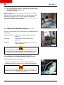
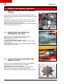
INTRODUCTION
MANITOU NORTH AMERICA, INC.
6401 IMPERIAL DRIVE
Waco, TX 76712--6803
For Parts Orders contact your Manitou North America Dealer or call:
Manitou North America, Parts Dept. 800--425--3727 or (254) 799--0232
Parts Dept. Fax: (254) 867--6504
Website: www.manitou--na.com
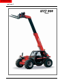
MVT628 T
-- E2 -OPERATOR/SERVICE
MANUAL
S/N: 411786 & above
THIS OPERATOR’S MANUAL MUST BE KEPT IN THE LIFT TRUCK. IT MUST BE READ AND
UNDERSTOOD BY THE LIFT TRUCK OPERATOR.
CATALOG 648371S
R11-10
INTRODUCTION
INTRODUCTION
MVT 628 T
MVT 628
Turbo
INTRODUCTION
INTRODUCTION
- INTRODUCTION TO SAFETY -
- ROUGH TERRAIN FORKLIFT TRUCK
GENERAL SAFETY STANDARDS - - - - - - - - - - - I
- SAFETY MESSAGES - - - - - - - - - - - - - - - - - - - - - - - - - - - - - - - - - - VII
- SAFETY DECALS - - - - - - - - - - - - - - - - - - - - - - - - - - - - - - - - - - - - - VIII
- TABLE OF CONTENTS - XV
- OPERATING AND SAFETY INSTRUCTIONS - - - - - - - - SECTION 1
- DESCRIPTION - - - - - - - - - - - - - - - - - - - - - - - - - - - - - SECTION 2
- MAINTENANCE - - - - - - - - - - - - - - - - - - - - - - - - - - - - - SECTION 3
- ELECTRICAL AND HYDRAULIC - - - - - - - - - - - - - - - - - SECTION 4
- PICKING UP THE ATTACHMENTS - - - - - - - - - - - - - - - SECTION 5
R05-05
INTRODUCTION
INTRODUCTION
ROUGH TERRAIN FORKLIFT TRUCK
GENERAL SAFETY STANDARDS
I
INTRODUCTION
ROUGH TERRAIN FORKLIFT TRUCK GENERAL SAFETY STANDARDS
STUDY THE OPERATOR/SERVICE MANUALS
The information in this manual provides general instructions for the safe operation and maintenance of your
forklift truck. This information is vital and must be clearly understood by the operator and serviceman. Study
this manual and the Rough Terrain Forklift Safety Manual (part no. 422494) thoroughly and carefully before
operating or servicing your forklift. Contact your dealer or Manitou North America, Inc. if you have any questions concerning your forklift, its operation, service or parts. Keep both manuals in the literature box on the
forklift available for reference. If either manual becomes illegible or is missing, contact your dealer for replacements immediately. This manual cannot cover every situation that might result in an accident. It is the responsibility of the operator to always remain alert for potential hazards and be prepared to avoid them!
ADDITIONAL RECOMMENDED LITERATURE:
ASME B56.6 is the national consensus standard for rough terrain forklift trucks. It contains rules about forklift safety, maintenance, safe operation, training, and supervision. Forklift owners should learn this standard
and make it available for their operators, service personnel, and supervisors. These standards can be
obtained from the American Society of Mechanical Engineers (ASME), 345 East 47th St., United Engineering
Center, New York, NY 10017. The following references are examples from the standard, addressing forklift
operators:
A.) OPERATOR TRAINING QUALIFICATIONS
1.) The user shall ensure that operators understand that safe operation is the operator’s responsibility. The
user shall ensure that operators are knowledgeable of, and observe, all safety rules and practices.
2.) Create an effective operator training program centered around user company’s policies, operating conditions, and rough terrain forklift trucks. The program should be presented completely to all new operators and
not be condensed for those claiming previous experience.
3.) Information on operator training is available from several sources, including rough terrain forklift truck manufacturers, users, government agencies, etc.
4.) An operator training program should consist of the following:
a.) careful selection of the operator, considering physical qualifications, job attitude, and aptitude;
b.) emphasis on safety of stock, equipment, operator, and other personnel;
c.) citing of rules and why they were formulated;
d.) basic fundamentals of rough terrain forklift truck and component design as related to safety, e.g.,
in.-lb (N-m) loading, mechanical limitations, center of gravity, stability, etc.;
e.) introduction to equipment, control locations, and functions. Explain how they work when used
properly and problems when used improperly.
f.) supervise practice on operating course remote from normal activity and designed to simulate
actual operations, e.g., lumber stacking, elevating shingles to the roof, etc.;
g.) oral, written, and operational performance tests and evaluations during and at completion of the
course;
h.) refresher courses, which may be condensed versions of the primary
course, and periodic “on job” operator evaluation;
i.) understanding of nameplate data and operator instructions and warning information appearing on
the rough terrain forklift truck.
B.) GENERAL SAFETY PRACTICES
1.) Rough terrain forklift trucks can cause injury if improperly used or maintained.
2.) Only authorized operators trained to adhere strictly to all operating instructions shall be permitted to operate rough terrain forklift trucks. Unusual operating conditions may require additional safety precautions, training, and special operating instructions.
3.) Modifications and additions which affect capacity or safe operation shall not be preformed without the manufacturer’s prior written approval. Where such authorization is granted, capacity, operation, and maintenance
instruction plates, tags, or decals shall be changed accordingly.
4.) If the rough terrain forklift truck is equipped with front end attachment(s) or optional forks, the user shall see
that the truck is marked to identify the forks or attachment(s), show the approximate weight of the truck and
fork or attachment combination, and show the capacity of the truck with forks or attachment(s) at maximum
elevation with load laterally centered.
5.) The user shall see that all nameplates and caution and instruction markings are in place and legible.
6.) The user shall consider that changes in load dimension may affect rough terrain forklift truck capacity.
II
INTRODUCTION
ROUGH TERRAIN FORKLIFT TRUCK GENERAL SAFETY STANDARDS (cont.)
B.) GENERAL SAFETY PRACTICES (cont.)
7.) Where steering can be accomplished with either hand and the steering mechanism is of a type that prevents road reactions from causing the handwheel to spin (power steering or equivalent), steering knobs may
be used. When used, steering knobs shall be of a type that can be engaged by the operator’s hand from the
top and shall be within the periphery of the steering handwheel.
8.) Experience has shown that rough terrain forklift trucks which comply with stability requirements are stable
when properly operated. However, improper operation, faulty maintenance, or poor housekeeping may contribute to a condition of instability and defeat the purpose of the requirements.
9.) Users shall give consideration to special operating conditions. The amount of forward and rearward tilt to
be used is governed by the application. Although the use of maximum rearward tilt is allowable under certain
conditions, such as traveling with the load lowered, the stability of a rough terrain forklift truck as determined
by standardized tests does not encompass consideration for excessive tilt at high elevations or the operation
of trucks with excessive off-center loads.
10.) Some of the conditions which may affect stability are ground and floor conditions, grade, speed, loading
(rough terrain forklift trucks equipped with attachments behave as partially loaded trucks even when operated
without a load on the attachment), dynamic and static forces, improper tire inflation, and the judgement exercised by the operator.
C.) OPERATING SAFETY RULES AND PRACTICES
1.) Safe operation is the responsibility of the operator.
2.) This equipment can be dangerous if not used properly. The operator shall develop safe working habits and
also be aware of hazardous conditions in order to protect himself, other personnel, the rough terrain forklift
truck, and other material.
3.) The operator shall be familiar with the operation and function of all controls and instruments before undertaking to operate the rough terrain forklift truck.
4.) Before operating any rough terrain forklift truck, truck operators shall have read and be familiar with the
operator’s manual for the particular truck being operated.
5.) Before starting to operate the rough terrain forklift truck:
a.) be in operating position and fasten seat belt;
b.) place directional controls in neutral;
c.) apply brakes;
d.) start engine.
6.) Do not start or operate the rough terrain forklift truck, any of its functions, or attachments from any place
other than the designated operator’s position.
7.) Keep hands and feet inside the operator’s designated area or compartment. Do not put any part of the
body outside the operator compartment of the rough terrain forklift truck.
8.) Never put any part of the body into the mast structure or between the mast and the rough terrain forklift
truck.
9.) Never put any part of the body within the reach mechanism of the rough terrain forklift truck or other attachments.
10.) Understand rough terrain forklift limitations and operate the truck in a safe manner so as not to cause injury
to personnel.
11.) Do not allow anyone to stand or pass under the elevated portion of any rough terrain forklift truck, whether
empty or loaded.
12.) Do not permit passengers to ride on rough terrain forklift trucks.
13.) Check clearance carefully before driving under electrical lines, bridges, etc.
14.) A rough terrain forklift truck is attended when the operator is less than 25 ft (7.6m) from the truck, which
remains in his view.
15.) A rough terrain forklift truck is unattended when the operator is 25ft (7.6m) or more from the truck, which
remains in his view, or whenever the operator leaves the truck and it is not in his view.
16.) Before leaving the operator’s position:
a.) bring rough terrain forklift truck to a complete stop;
b.) place directional controls in neutral;
c.) apply the parking brake;
d.) lower load-engaging means fully, unless supporting an occupied elevated platform;
e.) stop the engine;
f.) if the rough terrain forklift truck must be left on an incline, block the wheels;
g.) fully lower the load-engaging means.
17.) Maintain a safe distance from the edge of ramps, platforms, and other similar working surfaces.
18.) Do no move railroad cars or trailer with a rough terrain forklift truck.
III
INTRODUCTION
ROUGH TERRAIN FORKLIFT TRUCK GENERAL SAFETY STANDARDS (cont.)
C.) OPERATING SAFETY RULES AND PRACTICES (cont.)
19.) Do not use a rough terrain forklift truck for opening or closing railroad car doors.
20.) In areas classified as hazardous, use only rough terrain forklift trucks approved for use in those areas.
21.) Report all accidents involving personnel, building structures, and equipment to the supervisor or as
directed.
22.) Do not add to, or modify, the rough terrain forklift truck.
23.) Do not block access to fire aisles, stairways, and fire equipment.
24.) For rough terrain forklift trucks equipped with a differential lock, the lock should not be engaged when driving on the road or at high speeds or when turning. If the lock is engaged when turning, there could be loss of
steering control.
25.) Observe all traffic regulations including authorized speed limits. Under normal traffic conditions, keep to
the right, maintain a safe distance, based on speed of travel, from the truck ahead; and keep the truck under
control at all times.
26.) Yield the right-of-way to pedestrians and emergency vehicles such as ambulances and fire trucks.
27.) Do not pass another truck traveling in the same direction at intersections, blind spots, or at other dangerous locations.
28.) Slow down and sound the audible warning device(s) at cross-aisles and other locations where vision is
obstructed.
29.) Cross railroad tracks at an angle wherever possible. Do not park closer than 6 ft (1.8m) to the nearest rail
of a railroad track.
30.) Keep a clear view of the path of travel and observe other traffic, personnel, and safe clearances.
31.) If the load being carried obstructs forward view, travel with the load trailing.
32.) Ascend or descend grades slowly and with caution.
a.) When ascending or descending grades in excess of 5%, loaded rough terrain forklift trucks
should be driven with the load upgrade.
b.) Unloaded rough terrain forklift trucks should be operated on all grades with the load-engaging
means downgrade.
c.) On all grades, the load and load-engaging means shall be tilted back, if applicable, and raised
only as far as necessary to clear the road surface.
d.) Avoid turning, if possible, and use extreme caution on grades, ramps, or inclines; normally
travel straight up or down.
33.) Under all travel conditions, operate the rough terrain forklift truck at a speed that will permit it to be brought
to a stop in a safe manner.
34.) Travel with load-engaging means or load low and, where possible, tilted back. Do not elevate the load
except during stacking.
35.) Make starts, stops, turns, or direction reversals in a smooth manner so as not to shift load and/or overturn
the rough terrain forklift truck.
36.) Do not indulge in stunt driving or horseplay.
37.) Slow down for wet and slippery surfaces.
38.) Before driving over a dockboard or bridge plate, be sure that it is properly secured. Drive carefully and
slowly across the dockboard or bridge plate, and never exceed its rated capacity.
39.) Do not drive rough terrain forklift trucks onto any elevator unless specifically authorized to do so.
Approach elevators slowly, and then enter squarely after the elevator car is properly leveled. Once on the elevator, neutralize the controls, shut off engine, and set brakes. It is advisable that all other personnel leave the
elevator before truck is allowed to enter or leave.
40.) Avoid running over loose objects on the roadway surface.
41.) When negotiating turns, reduce speed to a safe level, and turn steering handwheel in a smooth sweeping
motion. Except when maneuvering at a very low speed, turn the steering handwheel at a moderate, even rate.
42.) Use special care when traveling without load, as the risk of lateral overturning is greater.
43.) Improper use of stabilizer controls (if so equipped) could cause rough terrain forklift truck upset. Always
lower the carriage before operating stabilizer controls.
44.) For rough terrain forklift trucks equipped with lateral leveling:
a.) Always level the frame before raising the boom or mast, with or without a load.
b.) Lateral leveling should not be used to position an elevated load; instead, lower the load and
reposition the rough terrain forklift truck.
45.) Handle only stable or safely arranged loads.
a.) When handling off-center loads which cannot be centered, operate with extra caution.
b.) Handle only loads within the capacity of the rough terrain forklift truck.
c.) Handle loads exceeding the dimensions used to establish rough terrain forklift truck capacity
with extra caution. Stability and maneuverability may be adversely affected.
IV
INTRODUCTION
ROUGH TERRAIN FORKLIFT TRUCK GENERAL SAFETY STANDARDS (cont.)
C.) OPERATING SAFETY RULES AND PRACTICES (cont.)
46.) When attachments are used, extra care shall be taken in securing, manipulating, positioning, and transporting the load. Operate rough terrain forklift trucks equipped with attachments as partially loaded trucks
when not handling a load.
47.) Completely engage the load with the load-engaging means. Fork length should be at least two-thirds of
load length. Where tilt is provided, carefully tilt the load backward to stabilize the load. Caution should be used
in tilting backward with high or segmented loads.
48.) Use extreme care when tilting load forward or backward, particularly when high tiering. Do not tilt forward
with load-engaging means elevated except to pick up or deposit a load over a rack or stack. When stacking
or tiering, use only enough backward tilt to stabilize the load.
49.) The handling of suspended loads by means of a crane arm (boom) or other device can introduce dynamic forces affecting the stability of a rough terrain forklift truck. Grades and sudden starts, stops, and turns can
cause the load to swing and create a hazard if not externally stabilized. When handling suspended loads:
a.) do not exceed the truck manufacturer’s capacity of the rough terrain forklift truck as equipped
for handling suspended loads.
b.) only lift the load vertically and never drag it horizontally;
c.) transport the load with the bottom of the load and the mast as low as possible;
d.) with load elevated, maneuver the rough terrain forklift truck slowly and cautiously, and only to
the extent necessary to permit lowering to the transport position;
e.) use tag lines to restrain load swing whenever possible.
50.) At the beginning of each shift and before operating the rough terrain forklift truck, check its condition,
giving special attention to:
a.) tires and their inflation pressure
b.) warning devices
c.) lights
d.) lift and tilt systems, load-engaging means, chains, cables, and limit switches
e.) brakes
f.) steering mechanism
g.) fuel system(s)
51.) If the rough terrain forklift truck is found to be in need of repair or in any way unsafe, or if it contributes to
an unsafe condition, the matter shall be reported immediately to the user’s designated authority, and the truck
shall not be operated until it has been restored to safe operating condition.
52.) If during operation the rough terrain forklift truck becomes unsafe in any way, the matter shall be reported
immediately to the user’s designated authority, and the truck shall not be operated until it has been restored to
safe operating condition.
53.) Do not make repairs or adjustments unless specifically authorized to do so.
54.) When refueling, smoking in the area shall not be permitted, the engine shall be stopped, and the operator shall not be on the rough terrain forklift
truck.
55.) Spillage of oil or fuel shall be carefully and completely absorbed or evaporated and fuel tank cap replaced
before restarting engine.
56.) Do not use open flames when checking electrolyte level in storage batteries, liquid level in fuel tanks, or
the condition of LPG fuel lines and connectors.
V
ROUGH TERRAIN FORKLIFT TRUCK GENERAL SAFETY STANDARDS (cont.)
D.) SUSPENDED LOADS
A jib or truss boom should ONLY be used to lift and place loads when the machine is stationary and the frame
is level. Transporting suspended loads must ALWAYS be done slowly and cautiously, with the boom and load
as low as possible. Use taglines to restrict loads from swinging, to avoid overturn.
The handling of suspended loads by means of a truss boom or other similar device can introduce dynamic
forces affecting the stability of the machine that are not considered in the stability criteria of industry test
standards. Grades and sudden starts, stops and turns can cause the load to swing and create a hazard.
Guidelines for “Free Rigging / Suspended Loads”
1.
DO NOT exceed the rated capacity of the telescopic handler as equipped for handling suspended
loads. The weight of the rigging must be included as part of the load.
2.
During transport, DO NOT raise the load more than 12 inches (305 mm) above the ground, or raise
the boom more than 45 degrees.
3.
Only lift the load vertically – NEVER drag it horizontally.
4.
Use multiple pickup points on the load when possible. Use taglines to restrain the load from swinging
and rotating.
5.
Start, travel, turn and stop SLOWLY to prevent the load from swinging. DO NOT exceed walking
speed.
6.
Inspect rigging before use. Rigging must be in good condition and in the U.S. comply with OSHA
regulation §1910.184, “Slings,” or §1926.251, “Rigging equipment for material handling.”
7.
Rigging equipment attached to the forks must be secured such that it cannot move either sideways or
fore and aft. The load center must not exceed 24 inches (610 mm).
8.
DO NOT lift the load with anyone on the load, rigging or lift equipment, and NEVER lift the load over
personnel.
9.
Beware of the wind, which can cause suspended loads to swing, even with taglines.
10.
DO NOT attempt to use frame-leveling to compensate for load swing.
WARNING
U.S. OSHA regulations effective November 8, 2010 (29 CFR Part 1926, Subpart CC - Cranes and Derricks in
Construction) include requirements for employers that use powered industrial trucks ("forklifts") configured
to hoist (by means of a winch or hook) and move suspended loads horizontally. In particular, this regulation
applies to any rough-terrain forklift (e.g., "telescopic handler") equipped with a jib or truss boom with a
hook (with or without a winch), or a hook assembly attached to the forks. [Note: This regulation is in
addition to the OSHA regulation that requires specific forklift operator training: §1910.178(l).]
When a forklift / telescopic handler is configured and used for hoisting, the employer must ensure that:
1.
Forklift, lift equipment and rigging have been inspected (each shift, month and year) and are in
good, safe condition and properly installed.
2.
An operator's manual and applicable load charts are on the forklift.
3.
Work zone ground conditions can support the equipment and load. Any hazardous conditions in the
work area have been identified, and the operator notified.
4.
Equipment is being used within its rated capacity and in accordance with the manufacturer's
instructions.
VI
5.
Operator and crew members have been trained in the safe use and operation of the equipment,
including how to avoid electrocution.
6.
During use, no part of the equipment, load line or load will be within the minimum clearance
distance specified by OSHA [10 feet (3.0 m), and more for lines rated over 50 kV] of any energized
power line, and any taglines used are non-conductive.
7.
In addition, for lift equipment with a rated capacity greater than 2000 lbs. (907 kg), the employer
must ensure that:
a.) An accessible fire extinguisher is on the forklift;
b.) Monthly and annual inspections are performed and documented, and records retained (three
months for monthly, one year for annual);
c.) Before November 10, 2014, operators must have had the additional training and qualification /
certification required by OSHA regulations §1926.1427 and §1926.1430.
Note: Refer to the full text of the OSHA crane regulation (29 CFR Part 1926, Subpart CC) for a detailed
description
VII
ROUGH TERRAIN FORKLIFT TRUCK GENERAL SAFETY STANDARDS (cont.)
CONCLUSION:
1.) ATTEND OPERATOR TRAINING CLASSES
The forklift operator must clearly understand all instructions concerning the safe operation of the forklift and all
safety rules and regulations of the work site. They must have successfully completed a training coarse in
accordance with the Powered Industrial Truck Standard (29 CFR 1910.178) as described by the Occupational
Safety and Health Administration (OSHA). They must be qualified as to their visual, hearing, physical, and
mental ability to operate the equipment safely. NEVER use drugs or alcohol while operating a forklift! NEVER
operate or allow anyone to operate a forklift when mental alertness or coordination is impaired! An operator
on prescription or over-the-counter drugs must consult a medical professional regarding any side effects of the
medication that may impair their ability to safely operate the forklift.
2.) CREATE A MAINTENANCE PROGRAM
OSHA recommends a maintenance log, listing repairs requested and completed, for each forklift. Also, “lock
out tag procedures” should be utilized. If the forklift malfunctions; park it safely, remove the key, tag “Do Not
Use”, and report the problem to the proper authority or authorized service personnel immediately.
ROUGH TERRAIN FORKLIFT TRUCK GENERAL SAFETY STANDARDS (cont.)
2.) CREATE A MAINTENANCE PROGRAM (cont.)
For the best forklift performance and operation, a maintenance program is required. Use the hour meter on
the instrument panel to keep maintenance properly scheduled (see SECTION TWO - “Servicing Schedule”).
For repairs on major components (engine, transmission, etc.), contact your nearest dealer for a Repair Manual.
Do not operate a forklift that is damaged or does not function properly. Only authorized personnel may make
repairs or adjustments to the lift truck. After repairs, the lift truck must be tested for safe operation before
returning to service.
3.) FORKLIFT KNOWLEDGE
Forklift trucks can cause serious injury if improperly used or maintained. Study all of the manuals provided for
your forklift model. Learn the locations and meanings of all safety decals. If any decals are illegible or missing, have them replaced immediately. Make sure all safety features provided by the original manufacturer are
in place and function properly. Do not operate a forklift with damaged, missing or unsafe components. Have
it repaired by authorized service personnel. Learn the functions of all controls, gauges, indicator lights, etc. on
the forklift. Know the speed/gear ranges, braking and steering capabilities, load ratings and clearances. When
referring to the location of forklift components, the terms “left”, “right”, “front”, and “rear” are related to the operator seated normally, facing forward in the operator’s seat. If you have any questions about the forklift, consult your supervisor. Failure to fully understand or obey safety warnings can result in serious injury or death!
4.) WORK SITE KNOWLEDGE
Before operating on a work site, learn the rules for movement of people, forklifts and all other traffic. Check
the size, weight, and condition of the loads you will be expected to handle. Verify that they are properly
secured and safe to transport. Learn where the loads are to be placed, planning your route for a safe
approach, watching for hazardous conditions. Will a signal man be required to help place the load? Remove
any debris which may cause tire damage or rupture. Plan your route around problem areas or have them corrected. Inform the supervisor of any unsafe conditions observed at the site. Examples of hazards: power
lines, cables, low clearance structures, garage doors, telephone pole guide lines, fencing, loose lumber, building materials, drop-offs, trenches, rough/soft spots, oil spills, deep mud, steep inclines, railroad tracks, curbs,
etc.. NEVER approach power lines, gas lines or other utilities with the forklift! Always verify that local,
state/provincial and federal regulations have been met. Report any accidents involving personnel, building
structures, and equipment to the supervisor immediately. Always remain alert - conditions are constantly
changing at the work site!
TECHNICAL SUPPORT
All data provided in this manual is subject to production changes, addition of new models, and improved product designs. If a question arises regarding your forklift, please consult your dealer or K-D Manitou, Inc. for the
latest information. When ordering service parts or requesting technical information, be prepared to quote the
applicable Model/Serial Numbers.
VIII
SAFETY MESSAGES
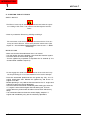
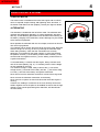
NOTE THE SAFETY ALERT SYMBOL (SHOWN BELOW). IT IDENTIFIES POTENTIAL
HAZARDS WHICH, IF NOT AVOIDED MAY RESULT IN INJURY OR DEATH! Also, observe
the safety messages places throughout this manual; providing special instructions, telling you when to take precautions
and to identify potential hazards. The safety messages are highlighted and outlined in a box similar to those shown in the
examples below.
SAFETY ALERT SYMBOL
NOTE or NOTICE
Provides information, special instructions or references about the lift truck.
IMPORTANT
Precautions which must be taken to avoid damage to the lift truck.
CAUTION
Indicates a potentially hazardous situation which, if not avoided, may result in minor or
moderate injury. May also alert unsafe practices.
WARNING
Indicates a potentially hazardous situation which, if not avoided, may result in death or
serious injury!
DANGER
Indicates an imminently hazardous situation which, if not avoided, will result in death or
serious injury.
CALIFORNIA PROPOSITION 65 WARNING
Diesel Engine Exhaust and some of its constituents are known to the State of California
to cause cancer, birth defects or other reproductive harm.
WARNING: Battery posts, terminals and related accesories and related accessories
contain lead and lead compounds. Wash hands after handling.
IX
INTRODUCTION
SAFETY DECALS
The purpose of this chapter is to introduce you to the safety messages, decals, and nameplates found on
your forklift truck. The decals are identified by name, part number, location, and a brief description. (The
forklift model logos, and other misc. decals not shown, can be found in your forklift parts manual.) The
decals illustrated may not be exactly the same as those installed on your forklift; installation of the decals
varies depending on the forklift model, series, decal updates, etc.. The size and location of some decals
limit the amount of information that can be placed upon it. For this reason, additional detailed information
not found on the decals is provided through-out this manual.
Every decal placed on the lift truck is important; they are constant reminders of safety and instructions that
should never be taken for granted. Even experienced operators can be seriously injured or killed by ignoring, refusing to enforce, or forgetting to follow safe operating procedures! Do not assume you know all safety issues concerning the decals. Before operating the lift truck; learn the meaning(s) of the decals as
described in this manual. If any decal becomes illegible or missing, have it replaced immediately! Always
replace decals using the same decal part no., unless otherwise specified by the manufacturer. For replacement decals not found in your parts manual, contact your nearest dealer. If you have any questions, contact
your supervisor or nearest dealer for advice before operating your forklift!
801011
Before Starting - 801011
(Boom equipped models). Location: on the brake fluid cover panel (to
the left and below the dash panel).
Safety Instructions - 420792
(Mast equipped models). Location: on or near the operator manual
storage case, and/or on the dash panel.
Instructions for the forklift operator; before operating the forklift.
Use of Seat Belt - 801012
(Boom equipped models). Location: to the right of the
operator, near the hydraulic control lever.
Instructs the operator to always wear the seat belt during
operations, and never jump from an over-turning forklift.
X
INTRODUCTION
SAFETY DECALS
Emergency and Parking Brake - 801010
Location: near the park brake lever.
Identifies the Emergency/Parking Brake Lever.
Alarm Must Sound - 496162
Location: on the dash, in direct view of the operator.
The backup alarm must sound when the forklift is placed in reverse gear.
No Riders - 420732
Location: on the cab entrance(s), and on or near wheel fenders and engine
cover.
Informs: riders are not allowed on the forklift.
Clear of Raised Boom - 801006
(Boom equipped models). Location: on both sides
of the boom nose.
Keep away from unsupported boom.
Clear of Power Lines - 801007
(Boom equipped models). Location: on both sides
of the boom nose.
Keep away from power lines.
XI
INTRODUCTION
SAFETY DECALS
Use of Frame Leveling - 801013
(Boom equipped models). Location: to the right of
the operator near the hydraulic control lever.
Frame leveling notice; load must be lowered.
Attachment and Boom Safety - 801009
(Boom equipped models). Location: on both sides of the
boom nose.
Important reminders of attachment and boom safety.
Hydraulic Coupling - 234805
Location: near the quick-disconnect adapters.
Stop the engine and release hydraulic pressure before changing
attachments.
Rotating Fan and Belt(s) - 801008
Location: on the radiator near the fan, and on any fan belt/pulley cover(s).
Keep hands and clothing away from rotating fan and belts.
XII
INTRODUCTION
SAFETY DECALS
Gear Shift Pattern - 33460
(4-speed transmission models). Location: near the gear shift lever.
Identifies the gear shift pattern of the forklift transmission.
Steering Mode - 184276
(4 wheel steer equipped models). Location: near the steering mode selection lever.
Identifies the steering mode selection.
221322
Mineral Oil (Brake Reservoir) - 221322 or 234800 has
been replaced by 164091.
Location: near the brake fluid reservoir where applicable.
Refer to the Operator/Service Manual for the correct brake fluid
(mineral oil) to be used in the brake system.
234800
XIII
INTRODUCTION
SAFETY DECALS
Hydraulic Oil - 234798 or 76573
Location: on the hydraulic tank or filler cap.
Identifies the hydraulic reservoir (tank) or filler cap.
Hydraulic Oil - 61024
Location: on the hydraulic tank.
Identifies the hydraulic reservoir (tank).
Anti-Freeze - 234799
Location: on the radiator, near the radiator filler cap.
Indicates required minimum to maximum anti-freeze protection (-220F to -400F).
Diesel Fuel - 161101
Location: on the fuel tank, near the filler cap.
Identifies the fuel tank, and use of diesel fuel.
No Step - 496735
Location: varies, depending on the forklift model.
Instructs personnel not to use the designated area as a step.
Do Not Tow - 494918
(Hydrostatic equipped models). Location: on the
dash, in view of the operator.
Towing the forklift will damage the transmission;
refer to the operator’s manual.
XIV
INTRODUCTION
SAFETY DECALS
Attachment Warning - 421016
(Boom equipped models). Location: on the boom coupler,
near where the retaining shaft is installed.
Reminder to operator; install attachment retaining shaft and
safety pin before operations.
Hook Here - 24653
Location: at points provided on the forklift, where straps or chains may be attached to
secure the forklift to a trailer during transport.
Fork Safety - 426641
(Mast equipped models). Location: on the front and back side of the mast’s outer rails,
at eye level (4 required).
Instructs personnel not to travel beneath or upon the lift truck forks.
Pinch Point, Large, 2.5 x 4.5 in. - 426643
Pinch Point, Small, 1.5 x 2.75 in. - 426642
(Mast equipped models). Location: on the front and rear sides
of the mast cross bracing.
Keep fingers away from the mast
crossbracing.
HAND THROTTLE DANGER - 804784
(Boom equipped models, option). Location: Near the hand throttle mechanism.
Reminder to operator; set parking brake before operating hand throttle.
Disengage hand throttle before leaving the forklift.
XV
INTRODUCTION
SAFETY DECALS
Acid in Battery - 801014
Location: in or near the battery
storage compartment.
Addresses battery hazards.
Jump Start Battery - 801015
Location: in or near the battery storage
compartment.
Jump start instructions.
Attachment Plate - 425995
Location: on the optional removeable forklift attachment.
Important manufacturer information about the attachment. Record this information for use
when contacting the maufacturer for parts and service.
Overhead Guard Data Plate - B6109
Location: attached to the overhead guard.
Overhead guard conformity.
496550
Forklift Data Plate - 496550
(Boom equipped models)
Forklift Data Plate - 496538
(Mast equipped models)
Location: within the operator’s compartment.
Important forklift truck identification. Record
this information for use when contacting the
manufacturer for parts and service.
XVI
496538
INTRODUCTION
MVT 628 T
TA B L E O F C O N T E N T S
1 - INSTRUCTIONS
- ORIGINAL SPARE PARTS AND TOOLS
- USER INSTRUCTIONS FOR THE LIFT TRUCK OPERATOR
- Warnings
- General instructions
- Driving instructions
- Handling instructions
- Load Handling
1
2
2
5
7
13
17
- LIFT TRUCK MAINTENANCE INSTRUCTIONS
- BEFORE STARTING UP A NEW LIFT TRUCK
20
22
2 - DESCRIPTION
-
SPECIFICATIONS
DIMENSIONS
LOAD CHART
INSTRUMENTS AND CONTROL
1
4
5
6
3 - MAINTENANCE
- FILTERING ELEMENTS AND BELTS
- LUBRICANTS
- MAINTENANCE SCHEDULE
A - Daily or every 10 hours service
B - Every 50 hours service
C - Every 250 hours service
D - Every 500 hours service or yearly
E - Every 1000 hours service or yearly
F - Every 2000 hours service or yearly
G - Occasional or annual maintenance
1
3
4
6
9
14
16
19
24
25
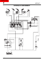
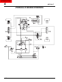
4 - ELECTRICAL AND HYDRAULIC SYSTEM
- ELECTRICAL SYSTEM
- Electrical system key
- Wiring diagram Tables
1
5
7
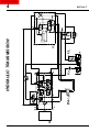
- HYDRAULIC UNIT
- Hydraulic movements
- Hydraulic steering and brakes
- Hydraulic transmission
14
14
16
18
OPTIONAL
ACCESSORIES
ENVISAGED
55--PICKING
UP THE
ATTACHMENTS
-
INTRODUCTION1
GENERAL RECOMMENDATIONS FOR USE OF A LIFT-TRUCK
ACCESSORY WITHOUT HYDRAULIC SYSTEM AND MANUAL LOCKING
ACCESSORY WITHOUT HYDRAULIC SYSTEM AND HYDRAULIC LOCKING (OPTIONAL)
ACCESSORY WITH HYDRAULIC SYSTEM AND MANUAL LOCKING (OPTIONAL)
ACCESSORY WITH HYDRAULIC SYSTEM AND HYDRAULIC LOCKING (OPTIONAL)
USING THE ITA TYPE FORK-HOLDER
TECHNICAL CHARACTERISTICS OF ACCESSORIES
2
4
5
6
7
8
12
XV
INTRODUCTION
MVT 628 T
INTRODUCTION
Our telescopic fork-lift trucks are designed with the sole aim of offering
the operator extremely simple operation and the mechanic the easiest
possible maintenance.
However, before putting the truck into operation for the first time, the
operator must read this manual and make sure he understands the
various topics it covers; it has been drawn up to help to solve any
operating and maintenance problem. Following these instructions, the
operator will be able to make full use of his telescopic fork-lift truck’s
potential.
“Right”, “left”, “forward” and “back” are as seen by someone in the
truck driver’s seat, looking forward.
When ordering spare parts or for all information of a technical nature,
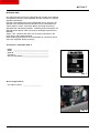
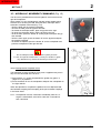
users are requested always to specify :
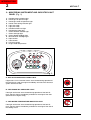
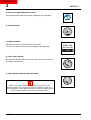
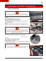
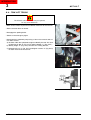
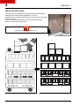
Constructor’s nameplate (FIG. 1)
- Model ______________________________________
- Series ______________________________________
- Serial N° ____________________________________
- Chassis N° __________________________________
- Year of manufacture ____________________________
MANITOU BF 44158 ANCENIS CEDEX FRANCE
Fig. 1
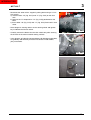
On the engine (FIG. 2)
- The engine number ____________________
Fig. 2
XVI
INTRODUCTION
MVT 628 T
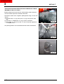
On hydrostatic drive (FIG. 3)
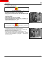
- MANITOU reference N° ________________________
- Serial N° ____________________________________
Fig. 3
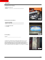
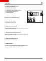
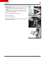
On front and rear axle (FIG. 4)
- Axle type and model ____________________________
- Serial N° of front axle ___________________________
- Serial N° of rear axle ___________________________
1 - Axle type and model
2 - Serial N°
1
2
Fig. 4
On cab (FIG. 5)
Cab No. ________________________________
To allow you to indicate these numbers with greater ease, you are
advised to make a note of them immediately in the spaces above.
Since the MANITOU policy is to aim for constant improvement of our
products, our range of telescopic fork-lift trucks may be subject to
some modifications without any obligation on us to inform our clientele.
Fig. 5
XVII
INTRODUCTION
INTRODUCTION
1 - OPERATING
AND SAFETY
INSTRUCTIONS
INTRODUCTION
INTRODUCTION
MVT 628 T
1
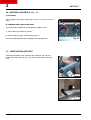
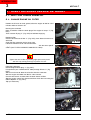
ORIGINAL REPLACEMENT PAR TS AND ATTACHMENTS
ALL MAINTENANCE ON OUR LIFT TRUCKS MUST BE CARRIED
OUT USING ORIGINAL PARTS.
BY ALLOWING NON-ORIGINAL PARTS TO BE USED, YOU RUN
THE RISK :
- Legally, of being liable in the event of an accident.
- Technically, of causing breakdowns to occur or of reducing your lift
truck's service life.
Using counterfeit parts or components not approved by the manufacturer may put an end to contract warranty terms and lead the maker to
withdraw the lift truck's certificate of compliance.
BY USING ORIGINAL PARTS DURING MAINTENANCE OPERATIONS, YOU ARE LEGALLY COVERING YOURSELF.
- Any user who procures parts from another quarter does so at his own
risk.
- Any user who modifies his lift truck or has it modified by a service company, must consider that a new item of equipment has been brought
onto themarket and therefore takes liability for it.
- Any user who copies original parts or has them copied is taking a risk
from the legal viewpoint.
- The certificate of compliance only binds the maker for parts chosen or
produced under the maker's control.
- The practicalities of maintenance terms are set out by the maker. The
maker is in no way liable in the event of the user not complying with
such terms.
THE MANUFACTURER BRINGS TO THE USER :
- His know-how and skill.
- Guaranteed quality work.
- Original replacement parts.
- Help with preventive maintenance.
- Effective help with diagnosing faults.
- Enhancements gained from feedback.
- Training for operating staff.
- Only the manufacturer knows the details of the lift truck design and
therefore has the best technological capability to carry out maintenance.
ORIGINAL REPLACEMENT PARTS ARE DISTRIBUTED
EXCLUSIVELY BY MANITOU
AND ITS DEALER NETWORK.
You can obtain the list of dealers by phoning
the spare parts department on :
TEL : 0033240091011
1
INTRODUCTION
1
MVT 628 T
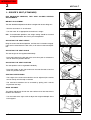
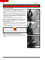
DRIVER’S OPERATING INSTRUCTION
WARNINGS
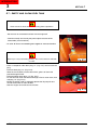
WHENEVER YOU SEE THIS SYMBOL IT MEANS :
WARNING! BE CAREFUL! YOUR SAFETY OR THE SAFETY
OF THE LIFT TRUCK IS AT RISK.
- Most accidents connected with the use, maintenance and repair of the
lift truck are due to non application of the basic safety instructions. By
being aware of the risks to which you are exposed and by taking the
necessary preventive measures, you should be able to avoid accidents
occurring.
- Any operation or manoeuvre not described in the instructions is prohibited, however, any person who does use another method must
first ensure that he is not putting himself, another person or the lift
truck in danger.
- The manufacturer is not able to anticipate all possible risk situations.
Therefore the safety instructions and notices given in the user manual and on the lift truck are not exhaustive.
Any bending of the rules in safety notices or the user, maintenance or
repair instructions for your lift truck may result in serious, or even fatal,
accidents.
We would remind users of the risks in driving at excessive speed with
regard to traffic conditions, particularly:
- Risk of loss of control on a poor-quality track.
- Increased stopping distance.
The user must remain in full control of his lift truck and should :
- Adapt his speed to each situation in order to be maintain his own
safety, that of others and of his equipment.
- Always be aware of his stopping distance.
2
INTRODUCTION
MVT 628 T
1
On the basis of experience, there are a number of possible situations
in which operating the lift truck is contra-indicated. Such foreseeable
abnormal uses, the main ones being listed below, are strictly forbidden.
- The foreseeable abnormal behaviour resulting from ordinary neglect,
but does not result from any wish to put the machinery to any
improper use.
- The reflex reactions of a person in the event of a malfunction, incident, fault, etc. during operation of the lift truck.
- Behaviour resulting from application of the "principle of least action"
when performing a task.
- For certain machines, the foreseeable behaviour of such persons as :
apprentices, teenagers, handicapped persons and trainees tempted
to drive a lift truck. Truck drivers tempted to operate a truck to win a
bet, in competition or for their own personal experience.
The person in charge of the equipment must take these criteria into
account when assessing whether or not a person will make a suitable
driver.
- Get to know the telescopic fork lift truck on the terrain where it is to
be used.
- Transport the load with the boom lowered and fully retracted.
- Position the forks at right-angles to the load to be lifted.
- Drive the truck at a speed appropriate to conditions and the state of
the ground.
- Never go too fast or brake sharply with a load.
- When picking up a load, check that the ground is as even as possible.
- Never attempt to carry out operations which exceed the lift truck’s
capabilities.
- Never raise a load in excess of the lift truck’s capacity and never
increase the size of the ballast.
- Drive around obstacles.
- Take care over electrical wires, trenches and recently-excavated or
filled ground.
- Never leave the engine running unattended.
- Use the parking brake when depositing difficult loads or on sloping
ground.
- Never leave the truck parked with a raised load.
- Never authorise anyone to approach or pass below a load.
- Always think of safety and only transportwell balanced loads.
- Never lift a load using one fork only.
- Drive with care and with reflexes alert.
- When the lift truck is not in use, lower the forks to the ground and
engage the parking brake.
- Never leave the ignition key in the truck unattended.
3
INTRODUCTION
1
MVT 628 T
- Never leave the truck loaded on a gradient of over 15% even with the
parking brake engaged.
- When lifting a load, take care that nothing and no-one interferes with
the movement and adopt proper handling procedures only.
- Comply with the data provided in the load diagrams.
- Never transport another person on the lift truck.
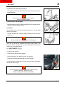
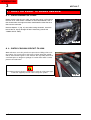
With every change of equipment, to avoid damaging
the hydraulic pipe unions :
- stop the I.C. engine
- turn key to position I
- release pressure from the circuit using the joystick
- Always check these pipe unions to ensure they are clean.
4
INTRODUCTION
1
MVT 628 T
GENERAL INSTRUCTIONS
A - DRIVER’S OPERATING INSTRUCTIONS
- Read the operator's manual carefully, making sure you understand it.
- The operator’s manual must always be kept in the lift truck, in the
place provided and in the language understood by the operator.
- Respect the safety notices and instructions given on the lift truck.
- It is compulsory to replace all plates or stickers which are no longer
legible or which have become worn or damaged.
B - AUTHORISATION TO OPERATE
(Or refer to the legislation for each particular country)
- Only qualified personnel may use the lift truck. Its use is subject to
authorisation to operate being given by the appropriate manager in the
user establishment.
- The user should always carry this authorisation to operate with him
while he is using the lift truck.
- The driver is not competent to authorise the driving of the lift truck by
another person.
- In addition, the vehicle should be used in accordance with good practice for the profession.
C - MAINTENANCE
- The user must immediately advise his superior if his lift truck is not in
good working order or does not comply with the safety notice.
- The operator is prohibited from carrying out any repairs or adjustments
himself, unless he has been trained for this purpose. He must keep the
lift truck properly cleaned if this is among his responsibilities.
- Carry out daily maintenance (See chapter : A - DAILY OR EVERY 10
HOURS SERVICE in paragraph : 3 - MAINTENANCE).
- Ensure tyres are adapted to the nature of the ground (See area of the
contact surface of the tyres in the chapter : CHARACTERISTICS in
paragraph : 2 - DESCRIPTION).
THERE ARE :
. SAND tyres.
. LAND tyres.
. Snow chains.
There are optional solutions, consult your agent or dealer.
Do not use a worn or damaged tyre.
The fitting of foam inflated tyres is prohibited
and is not guaranteed by the manufacturer,
excepting prior authorisation.
5
INTRODUCTION
1
- For your own and other people's safety, it is forbidden to modify the
structure and settings of the various components of your lift truck yourself (Hydraulic pressure, relief valve calibration, I.C. engine running
speed, addition of extra equipment etc.). The same holds with regard
to any suppression or modification of the safety systems, in which case
the maker would no longer be liable.
Regular inspection of your lift truck is mandatory if it is to be kept in
conforming condition. The frequency of such checks are defined by the
current legislation of the country in which the lift truck is being operated.
Maintenance or repairs other than those detailed in part : 3 - (MAINTENANCE) must be carried out by qualified personnel (Consult your
agent or dealer) and under the necessary safety conditions to maintain
the health of the operator and any third party.
D - ENVIRONMENT
- A lift truck operating in an area without fire extinguishing equipment
must be equipped with an individual extinguisher. There are optional
solutions, consult your agent or dealer.
- Take into account climatic and atmospheric conditions of the site of
utilisation.
For operation under average climatic conditions, i.e. : between 5°F
and 95°F, correct levels of lubricants in all the circuits are checked
in production. For operation under more severe climatic conditions,
before starting up, it is necessary to drain all the circuits, then ensure
correct levels of lubricants using lubricants properly suited to the relevant ambient temperatures. It is the same for the cooling liquid (For
more information, contact your agent or dealer).
. Protection against frost (See chapter : LUBRICANTS AND
FUEL in paragraph : 3 - MAINTENANCE).
. Adaptation of lubricants (Ask your dealer for information).
. Engine filtration.
. Lighting (Working headlight).
Optional solutions exist, consult your dealer.
Use of a lift truck is prohibited in protected areas (e.g. refinery, explosive atmosphere). For use in these areas,specific equipment is available as an option. Consult your dealer.
IF NECESSARY, CONSULT YOUR DEALER.
6
MVT 628 T
INTRODUCTION
MVT 628 T
1
OPERATING INSTRUCTIONS
A - DRIVER’S OPERATING INSTRUCTIONS
- Wear clothes suited for driving the lift truck, avoid loose clothes.
- Never operate the vehicle when hands or feet are wet or soiled with
greasy substances.
- For increased comfort, adjust the driver’s seat to your requirements
and adopt the correct position in the driver’s cab.
- The operator must always be in his normal position in the driver’s cab.
It is prohibited to have arms or legs, or generally any part of the body,
protruding from the driver’s cab of the lift truck.
- Always remember to fasten your seat belt and adjust it to your requirements.
- The control units must never in any event be used for any other than
their intended purposes (e.g. climbing onto or down from the lift truck,
portmanteau, etc.).
- If the control components are fitted with a forced operation (lever lock)
device, it is forbidden to leave the cab without first putting these controls in neutral.
- Never allow a passenger to travel on the lift truck in the driver’s cab.
B - BEFORE STARTING THE LIFT TRUCK
- If the lift truck is new, refer to chapter : BEFORE STARTING UP A NEW
LIFT TRUCK in paragraph : 1 - OPERATING AND SAFETY INSTRUCTIONS.
- Check the condition of the tyres and the tyre pressures (See chapter :
CHARACTERISTICS in paragraph : 2 - DESCRIPTION).
- Before starting the lift truck, check the different levels :
. Engine oil.
. Hydraulic reservoir oil.
. Transmission oil.
. Cooling liquid.
. Brakes fluid.
- Also check for possible leakage of oil Brakes fluid, fuel or liquid from the
lift truck.
- Check the closing and locking of the hood.
- Whatever his experience as a truck driver is, the operator is advised to
familiarize himself with the position and operation of all the controls
and instruments before operating the lift truck.
7
INTRODUCTION
1
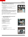
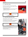
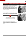
C - STARTING THE LIFT TRUCK
SAFETY NOTICE
The lift truck must only be started up or manoeuvred when the operator is sitting in the driver’s cab, with his seat belt adjusted and fastened.
- Never try to start the lift truck by pushing or towing it.
This movement could seriously damage the transmission. If it is necessary to tow the lift truck, relieve the hydrostatic transmission (See
chapter: H – OCCASIONAL MAINTENANCE under section: 3 - MAINTENANCE).
INSTRUCTIONS
- Make sure that the forward/reverse lever is in neutral.
- Turn the ignition key to the position I to activate the electrical system.
- Check the level on the fuel level gauge.
- Turn the ignition key to position II to preheat for 15 seconds (If the
environmental conditions require it).
Do not engage the starter motor for more than 15 seconds and carry
out the preheating for 10 seconds between unsuccessful attempts.
- Press the accelerator pedal and turn the ignition key fully : the I.C.
engine should then start. Release the ignition key and let the I.C.
engine run at idle.
- Before operating in very cold environment wait for the I.C. engine and
hydraulic systems to heat up adequately.
- Check all control instruments immediately after starting up, when the
I.C. engine is warm and at regular intervals during use, so as to
quickly detect any faults and to be able to correct them without any
delay.
- If an instrument does not show the correct display, stop the I.C.
engine and immediately carry out the necessary operations.
8
MVT 628 T
INTRODUCTION
MVT 628 T
1
D - DRIVING THE LIFT TRUCK
SAFETY NOTICE
- Always drive the lift truck with the forks or attachment at approximately 12 in. from the ground, i.e. In the transport position.
- Familiarise yourself with the lift truck on the terrain where it will be
used.
- Ensure that the service brakes and the sound alarm are working
properly.
- Drive according to, and at an appropriate speed for, the conditions
and state of the terrain.
- Slow down before executing a turn.
- In all circumstances make sure you are in control of your speed.
- On damp, slippery or uneven terrain, drive slowly.
- Brake gently, never abruptly.
- Only use the lift truck’s forward/reverse lever from a stationary position and never do so abruptly.
- Always remember that hydraulic type steering is extremely sensitive
to movement of the steering wheel, so turn it gently and not jerkily.
- Never leave the I.C. engine on when the lift truck is unattended.
- Look in the direction you are travelling and always keep clear visibility
of the road. Use the left and right rear view mirrors frequently and
ensure that they are kept in good condition, are clean and correctly
adjusted.
- Never use the truck in places poorly lighted.
- When working at night, ensure that your lift truck is fitted with full
beam lights. There are optional solutions, consult your agent or dealer.
- Drive around obstacles.
- Never move onto a loading platform without having first checked :
. That it is suitably positioned and madefast.
. That the unit to which it is connected (Wagon, lorry, etc.) will
not shift.
. That this platform is prescribed for the total weight of the lift
truck to be loaded.
. That this platform is prescribed for the width of the lift truck.
- Never move onto a foot bridge, floor or freight lift, without being certain
that they are prescribed for the weight and size of the lift truck to be
loaded and without having checked that they are in sound working
order.
Take extreme care with loading platforms, trenches, scaffolding,
recently dug and/or backfilled ground.
- The loaded lift truck must not travel at speeds in excess of 6 km/h.
MOVEMENT INSTRUCTIONS
- Check the transmission oil level.
- Raise the forks or attachment to the transport position approximately
12 in. from the ground.
- Select the required steering mode.
- Shift the forward/reverse lever to the selected direction of travel.
- Release the parking brake and accelerate gradually until the lift truck
moves off.
9
INTRODUCTION
1
E - STOPPING THE LIFT TRUCK
SAFETY NOTICE
- Before stopping the lift truck after a long working period, leave the I.C.
engine idling for a few moments, to allow the coolant liquid and oil to
lower the temperature of the I.C. engine and transmission.
This precaution must be strictly observed if the I.C. engine frequently
stops.
- Never leave the ignition key in the lift truck when the lift truck is unattended.
- When the lift truck is stationary, place the forks or attachment on the
ground, place the gear lever in neutral, apply the parking brake and
put the forward / reverse lever in neutral.
- If the driver has to leave his cab, even for a moment, it is essential to
place the gear lever in neutral, apply the parking brake and put the
forward/reverse lever in neutral.
- Make sure that the lift truck is not stopped in any position that will
interfere with the traffic flow and at less than six ft. from the track
of a railway.
- In the event of prolonged parking on a site, protect the lift truck from
bad weather, particularly from frost (Check the level of antifreeze),
close the rear window, lock the cab door and ensure that the hood is
properly secured.
STOP INSTRUCTIONS
- Park the lift truck on flat ground or on an incline lower than 15 %.
- Place the forward/reverse lever in neutral.
- Apply the parking brake.
- Completely retract the boom.
- Lower the forks or attachment to rest on the ground.
- Stop the I.C. engine.
- Remove the ignition key.
- Check the closing and locking of door, rear window and hood.
Before leaving your driver's cabin, ensure that you have carried out all
operations for stopping the lift truck, for your safety and the safety of
others.
10
MVT 628 T
INTRODUCTION
MVT 628 T
1
F - DRIVING THE LIFT TRUCK ON THE PUBLIC HIGHWAY
SAFETY INSTRUCTIONS
- Lift truck drivers, driving on the public highway, must abide by the
general provisions relative to highway traffic.
- The lift truck must conform to the provisions of the Highway Code. If
necessary, optional solutions exist, consult your dealer.
Transport of loads on the public highway is forbidden and attachments
mounted on the lift truck must be fitted with equipment in accordance
with regulations or else dismounted.
INSTRUCTIONS FOR DRIVING ON ROADS
- Ensure that the flashing light is installed and is in perfect working
order.
- Dipped headlights working also during hours and on roads where it is
not obligatory to use visual and lighting indicator devices.
- Check the headlights, turn indicators and windscreen wipers to
ensure they are clean and in perfect working condition.
- Check the position of the rear-view mirrors.
- Check wheel alignment and select the steering mode: TRAVELLING
ON ROADS.
- Position the rear axle steering mechanical block.
- Ensure that the fuel level is sufficient.
- Ensure that the truck is fitted with all the accessories required for
traveling on roads (depending on the model and country).
- Keep the boom retracted and the attachment about 12 in. above
ground level.
- Cut out the operating system control by means of the red button.
- The vehicle can only circulate without load.
- The vehicle must not be used for transporting the company personnel.
While on the road, do not put the reverse gear in neutral to maintain lift
truck exhaust brake.
11
INTRODUCTION
1
G - DRIVING THE LIFT TRUCK WITH TRAILER ON ROADS
- To use a trailer, observe the regulations applicable in the country of
use (maximum permitted speed, braking system, maximum trailer
weight, etc.).
- Remember to connect the electrical system of the lift truck to that of
the trailer.
- Do not use a trailer if the unit weight of the load is greater than that
specified by Highway Code.
- Do not use a braked trailer if the lift truck does not have a trailer
braking system.
- Remember to connect the lift truck braking system to that of the trailer.
- The total permitted weight for transport must not exceed the maximum permitted by the manufacturer (See the lift truck manufacturer’s
identification plate).
H - OPERATING THE LIFT TRUCK WITH A FRONT-END ATTACHMENT ON A PUBLIC HIGHWAY
- For driving with an attachment, check the regulations currently
applicable in your country.
- The attachment must not exceed the overall width of the lift truck.
- Do not mask the lighting range of the front headlamps.
- Set the attachments shields in place
- If necessary, fit the block spacer on the lifting and slewing cylinder.
- Front dimensions of equipment indicated on all three sides with 4
in. wide alternate white and red reflecting stripes, slanting 45°
(Follow the specific instructions for each type of equipment).
IF NECESSARY, CONSULT YOUR DEALER.
12
MVT 628 T
INTRODUCTION
MVT 628 T
1
HANDLING INSTRUCTIONS
A - GENERAL
- Ensure the correct functioning of your lift truck’s attachments.
- Do not attempt to carry out operations which exceed the capacities of
your lift truck or attachments.
- It is prohibited to increase the counterweight value in any way.
- It is strictly prohibited to carry or to lift up persons using the lift truck,
unless the vehicle is specially equipped for this purpose and has the
corresponding certificate of conformance for lifting people.
- Avoid travelling for a long distance in reverse.
- When lifting or lowering the boom ensure the control lever is moved
slowly and smoothly (whether operating with or without a load).
B - ATTACHMENTS
- Ensure that the attachment is correctly fitted and locked to its frame.
- Conform to the limits on the load chart for the attachment.
- Verificare che i pallet, le casse, ecc., siano in buono stato e adeguate
al carico da sollevare.
- Position the forks perpendicular to the load to be lifted, taking account
of the load’s centre of gravity.
- Never lift a load with a single fork.
- Never lift a sling load with a single fork or with the carriage. Optional
solutions exist, consult your dealer.
- If not utilised, place the attachment in horizontal on the ground (For
unstable attachments, ensure they are secured using wedges).
- Ensure that rapid hydraulic connections on the attachment system are
clean and protected.
- Carry out the following procedure before changing hydraulic attachments to prevent damage to the quick release couplings :
- stop the I.C. engine
- turn key to position I
- release pressure from the circuit using the joystick
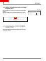
C - ENVIRONMENT
- Verify that the lighting in suitable.
- Ensure that no person or object is in the vicinity before raising the load.
Don’t make any sudden manoeuvres.
- In the case of work near aerial lines, ensure that the safety distance is
sufficient between the working area of the lift truck and the aerial line.
You must consult your local electrical agency.
13
INTRODUCTION
1
You could be electrocuted or seriously injured if you operate or park
the lift truck too close to power cables. You are strongly advised to
ensure that the safety rules on the site conform to the local regulations
in force regarding all types of work carried out close to power cables.
- Do not allow anybody to come near the working area of the lift truck or
pass beneath an elevated load.
- When using the lift truck on a slope, before raising the jib, ensure that
the ground is horizontal.
- Travelling on a longitudinal slope :
• Drive and brake gently.
• Moving without load : Forks or attachment facing downhill.
• Moving with load : Forks or attachment facing uphill.
- Ensure that scaffolding, loading platform or pile are capable of bearing
the weight.
- Ensure the stability and solidity of the ground before depositing a load.
14
MVT 628 T
INTRODUCTION
MVT 628 T
1
D - HANDLING
- Always consider safety and only transport balanced and correctly
secured loads to avoid any risk of tipping.
- Fully engage forks under the load and move it in the transport position
(The forks 12 in. from the ground, the jib retracted to the maximum
and the carriage sloping backwards).
- For obvious reasons regarding the lift truck’s stability and clear visibility of the surrounding environment, only move the lift truck when the jib
is in the transport position.
- Do not manoeuvre the lift truck with the jib in the raised position unless
under exceptional circumstances and then with extreme caution, at
very low speed and using gentle braking. Ensure that visibility is adequate and get another person to guide you along if necessary.
-
Never shift the position of the load while the lift truck is in motion.
Never drive too fast or brake abruptly when carrying a load.
During handling, drive at low speed.
Check the load, particularly when turning corners and especially if it is
very bulky.
- Secure unstable loads.
- Handle loads with caution, at slow speed, without sudden jerks when
moving them at significant heights and jib extention.
In the event of high winds or storms, do not carry out handling work
that jeopardizes the stability of the lift truck and its load.
- Do not change direction sharply and at high speed.
In the event of the lift truck overturning, do not try to leave the cab.
DO NOT TRY TO JUMP CLEAR STAY IN THE CAB WITH YOUR
SEAT BELT FASTENED.
- Apply the parking brake when lifting or depositing a difficult load or
when on an incline.
- Do not stop the lift truck with the load in an elevated position.
- Do not leave a laden lift truck with the parking brake applied on an
incline which exceeds 15 %.
15
INTRODUCTION
1
E - VISIBILITY
- Constantly keep clear visibility of the road, either direct view (looking
backwards when reversing) or indirect view using the panoramic rear
view mirrors to check for people, animals, holes, obstacles, change of
slope, etc.
- Since visibility can be reduced on the right side when the jib is raised,
ensure clear visibility of the road before raising the jib and before
undertaking any manoeuvres.
- If the visibility in forward motion is not sufficient because of the bulkiness of the load, drive in reverse motion. This manoeuvre must remain
exceptional and for short distances.
- Ensure you have good visibility (Clean windows, adequate lighting,
correctly adjusted rear view mirror, etc.).
- Signaling and lighting on the lift truck must take account of the conditions of use. The standard lighting system may not be sufficient for certain applications or night time road use.
Optional accessories are available.
Consult your agent or dealer.
IF NECESSARY, CONSULT YOUR DEALER.
16
MVT 628 T
INTRODUCTION
1
MVT 628 T
LOAD HANDLING
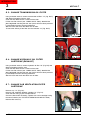
A
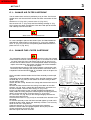
A - WEIGHT OF LOAD AND CENTRE OF GRAVITY
24 IN.
500 mm
Carrying a load greater than the rated capacity for the lift truck or for
the attachment is prohibited.
B
- Before taking up a load, you must know its weight and its centre of
gravity.
- The load chart relating to your lift truck is valid for a weight with its centre of gravity 24 in. from the heel of the forks (Fig. A). For a load with
a higher centre of gravity, consult your agent or dealer.
- For irregular loads, determine the centre of gravity in the transverse
direction before handling (Fig. B).
For loads with a moving centre of gravity (e.g. liquids), take account of
the variations in the centre of gravity in order to determine the load to
be handled (Consult your agent or dealer) and be vigilant and take
extra care to limit these variations as far as possible.
C
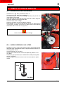
B - TAKING UP A LOAD ON THE GROUND
- Position the lift truck perpendicular to the load, with the jib retracted
and the forks in a horizontal position (Fig. C).
- Adjust the fork spread and centering in connection with the load (Fig.
D) (Optional solutions exist, consult your dealer).
D
Beware of the risks of trapping or squashing limbs when manually
adjusting the forks. Always maintain an equal distance between the
forks and the centre of the carriage in order to keep
the load completely stable.
E
- Slowly move the life truck forward (1) and stop with the forks in front of
the load (Fig. E), if necessary, slightly lift the jib (2) while taking up the
load.
- Apply the parking brake and place the forward/reverse lever in neutral.
- Slightly lift the load (1), tilt the carriage backwards (2) in the transport
position (Fig. F).
1
2
F
2
Tilt the carriage sufficiently backwards to ensure the load’s stability
when braking whilst maintaining the load balance.
1
17
INTRODUCTION
1
MVT 628 T
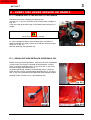
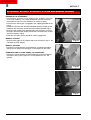
C - TAKING UP A HIGH LOAD
G
Under no circumstances should you pick up a load if the lift truck is not
in a horizontal position.
- Ensure that the forks will easily pass under the load.
- Position the lift truck perpendicular to the load with the forks in a horizontal position (Fig. G) manoeuvring gently and carefully (See paragraph : E - VISIBILITY in the chapter : HANDLING INSTRUCTIONS for
visibility of the road) .
H
Always think about keeping the distance necessary to fit the forks
under the load, between the pile and the lift truck (Fig. G) and use the
shortest possible length of jib.
I
2
- Stop with the forks in front of the load (Fig. H). Engage the parking brake
and place the forward/reverse lever in neutral.
- Slightly lift the load (1) and incline the forks carriage (2) backwards to
stabilize the load (Fig. I).
Tilt the load sufficiently backwards to ensure its stability (loss of load on
braking) without upsetting the balance of the load in so doing.
1
J
1
2
- If possible lower the load without shifting the lift truck. Lift the jib (1) to
release the load, retract (2) and lower the jib (3) to bring the load into
the transport position (Fig. J).
- If this is not possible, back the lift truck up. Manoeuvring very gently and
carefully (See paragraph : E - VISIBILITY in the chapter : HANDLING
INSTRUCTIONS for visibility of the road), back up the lift truck (1) to
release the load, retract (2) and lower the jib (3) to bring the load into the
transport position (Fig. K).
3
K
2
3
1
18
INTRODUCTION
1
MVT 628 T
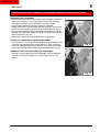
D - LAYING A HIGH LOAD
L
Under no circumstances should you lay down a load if the lift truck is
not in a horizontal position.
- Approach the load in the transport position in front of the pile (Fig. L).
- Lift and extend the jib (1) (2) until the load is above the pile, if necessary move the lift truck forward (3) (Fig. M) manoeuvring very gently
and carefully (See paragraph : E - VISIBILITY in the chapter : HANDLING INSTRUCTIONS for visibility of the road). Apply the parking
brake and place the forward/reverse lever in neutral.
- Place the load in a horizontal position and lay it down on the pile by
lowering and retracting the jib (1) (2) in order to position the load correctly (Fig. N).
- Free the forks by alternately retracting and lifting the jib (3) (Fig. N), or,
if possible, by reversing the lift truck (3) (See paragraph : E - VISIBILITY in the chapter : HANDLING INSTRUCTIONS for visibility of the
road). Then bring the jib into the transport position.
M
2
1
3
N
E - TAKING UP A LOAD WITHOUT PALLET
- Tilt the carriage (1) forwards and extend the jib (2) while simultaneously crowding the carriage backwards to slip the forks under the load
(Fig. O). If necessary, wedge the load.
3
1
2
3
F - LOAD STATUS INDICATOR
- Always watch the load status indicator while handling a load.
O
If the load status indicator alarm is actived, do not carry out the movements said to be "WORSENING", which are the following :
A - Extend the jib.
B - Lower the jib.
2
3
1
If the load status indicator alarm is actived, carry out in all security
movements in the following order (Fig. P) :
1 - Fully retract the jib.
2 - If it’s necessary lift the jib.
3 - Lower the jib in order to lay the load.
P
2
1
3
The reading on the device can be falsified if the steering wheel is fully
turned or if the rear axle has swung to the maximum extent. Before
lifting a load, always make sure the steering wheel is not turned all the
way, and that the rear axle has not completely swung.
19
INTRODUCTION
1
LIFT TRUCK MAINTENANCE INSTRUCTIONS
MAINTENANCE INSTRUCTIONS
A - GENERAL
- Read the operator's manual carefully and ensure you understand it.
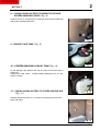
- Stop the I.C. engine, when an intervention is necessary.
- Wear clothes suitable for the maintenance of the lift truck, avoid
wearing jewellery and loose clothes. Tie and protect your hair, if necessary.
- Ensure the area is sufficiently ventilated before starting the lift truck.
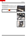
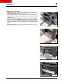
Make sure that the disposal of process materials and of spare parts is
carried out in total safety and ecological way.
- Carry out all repairs immediately, even if the repairs concerned are
minor.
- Repair all leaks immediately, even if the leak concerned is minor.
- Do not attempt to loosen unions, hoses or any hydraulic component
with the circuit under pressure.
The handling and removal of the balancing valves or safety valves
which may be fitted to the cylinders of your lift truck can be dangerous.
A balancing valve must only be removed when the cylinder concerned
is at rest and the hydraulic circuit is depressurised.
This operation can only be carried out by authorised staff.
- Do not smoke or approach the lift truck with a flame, when the fuel tank
is open or is being filled.
- Take care not to burn yourself (Exhaust, radiator, I.C. engine, etc.).
- Disconnect the negative cable terminal (-) from the top of the battery
before working on the electrical circuit or on the lift truck (e.g. :
Welding).
- Do not drop metallic items on the battery.
- When carrying out electric welding work on the lift truck, connect the
negative cable from the equipment directly to the part being welded,
so as to avoid high tension current passing through the alternator.
20
MVT 628 T
INTRODUCTION
MVT 628 T
1
B - MAINTENANCE
- The maintenance and the keeping in compliance of the lift truck are
compulsory.
- Carry out daily maintenance (See chapter : A - DAILY OR EVERY 10
HOURS SERVICE in paragraph : 3 - MAINTENANCE).
- Do not run the I.C. engine without air filter, or with oil, water or fuel
leaks.
Wait for the I. C engine to cool before removing the radiator cap.
- Change the filter cartridges (See servicing schedules in chapter :
FILTERS CARTRIDGES AND BELTS in paragraph : 3 - MAINTENANCE).
C - LEVELS
- Use the recommended lubricants (Never use contaminated lubricants).
- Do not fill the fuel tank when the I.C. engine is running.
- Only fill up the fuel tank in areas specified for this purpose.
D - WASHING
- Clean the lift truck or at least the area concerned before any intervention.
- Remember to close the door and the rear window of the cab.
- During washing, avoid the articulations and electrical components
and connections.
If necessary, protect against penetration of water, steam or cleaning
agents, components susceptible of being damaged, particularly electrical components and connections and the injection pump.
- Clean the lift truck of any fuel, oil or grease trace.
FOR ANY INTERVENTION OTHER THAN REGULAR MAINTENANCE, CONSULT YOUR DEALER.
21
INTRODUCTION
1
BEFORE STAR TING UP A NEW LIFT TRUCK
INTRODUCTION
- Our lift trucks have been designed for easy handling by the operator
and maximum ease of maintenance for the mechanic.
- However, before commencing to operate the lift truck, the user
should carefully read and understand the various chapters of this
manual which has been provided to solve driving and maintenance
problems. By following these instructions the user will be able to take
full advantage of the versatility of this lift truck.
- The operator must familiarize himself with the positions and functions
of all the controls and instruments before operating the lift truck.
Do not attempt to start a new lift truck before the following checks have
been carried out :
LUBRICATION
- Check that all the correct grades of oils and greases that are required
are available ; see chapter : SERVICING SCHEDULE in paragraph : 3
- MAINTENANCE and top up if necessary.
For operation under average climatic conditions, i.e. : between 5 °F
and 95 °F, correct levels of lubricants in all the circuits are checked in
production. For operation under more severe climatic conditions, before
starting up, it is necessary to drain all the circuits, then ensure correct
levels of lubricants using lubricants properly suited to the relevant ambient temperatures. It is the same for the cooling liquid (Contact your
dealer for information, if necessary).
DRY AIR FILTER
- Ensure that the air filter is undamaged and not blocked.
- Tighten the fastening devices if necessary.
Never run the I.C. engine with the air filter removed or damaged.
COOLING CIRCUIT
- Always check the cooling liquid level before starting up the lift
truck.
HYDRAULIC CIRCUIT
- Visually check for leakage or oil leaks from the connections, hoses,
pipes and unions. Tighten or check the defective connections, if necessary.
- Also check the oil level in the tank.
22
MVT 628 T
INTRODUCTION
MVT 628 T
1
BRAKING SYSTEM
- Check by a visual examination that there are no leaks or oil oozing in
the hoses, connections and unions. If necessary, tighten or repair the
defective connections.
- Also check the oil level in the tank.
Use only the recommended oil to avoid damaging the brake circuit
(see chapter - LUBRICANTS in section: 3 - MAINTENANCE).
TYRES
- Make sure that the wheel nuts are correctly tightened (See chapter :
A - DAILY OR EVERY 10 HOURS SERVICE in paragraph : 3 - MAINTENANCE) and that the tyre pressures are correct (See chapter :
CHARACTERISTICS in paragraph : 2 - DESCRIPTION).
FUEL SYSTEM
- Check that all fuel lines are secured.
- If necessary drain the fuel filter and bleed the fuel system of air.
ELECTRICAL CIRCUIT
- Check the level and the density of the electrolyte in the battery (See
chapter : B - EVERY 50 HOURS SERVICE in paragraph : 3 - MAINTENANCE).
- Check the components of the electrical system, the connections and
fastening devices.
IF NECESSARY, CONSULT YOUR DEALER.
23
INTRODUCTION
INTRODUCTION
2 - DESCRIPTION
INTRODUCTION
INTRODUCTION
2
MVT 628 T
S P E C I F I C AT I O N S
ENGINE
- Type
- Cylinders number
- Number of strokes
- Injection system
- Firing order
- Displacement
- Bore
- Stroke
- Volumetric ratio
- Nominal rpm
- Idling rpm
- Power ISO/TR 14396
- Maximum torque 1400 min-1
PERKINS 1104C-44T
4
4
direct
1-3-4-2
4400 cm3
260 cu.in.
105 mm
4,13 inches
127 mm
5 inches
17,5:1
2200 rpm
800 rpm
101 cv / 74,5 kw
412 Nm - 42 kgm
COOLING SYSTEM
- Type
- Suction speed fan
- Number of blades
Water cooled
2300 min-1
- Diameter
7
500 mm
19,69 inches
- Thermostat
- Complete open
82° C
179,6°F
ELECTRICAL CIRCUIT
- Ground
- Battery
- Alternator
- Voltage regulator
- Starting
Negative
12 V - 120 Ah
12 V - 75 Ah
incorporated in the alternator
12 V
BRAKE
- Type
- Service brake
Disc brakes in oil bath
Foot pedal actuated on both axles.
- Parking brake
Hydraulic actuated on front axle, negative type.
1
INTRODUCTION
2
MVT 628 T
TRANSMISSION
- Type
- Type
Performance
Reverser
No. of wheels
Hydrostatic
Pump and variable displacement
engine
0/35 km/h
0/21,7 mph
Electro-hydraulic
4
HYDRAULIC CIRCUIT
- Lifting, tilting of telescopic boom and device
- Type of pump
Gear type
- Delivery
80 L/min
- Pressure
235 bars
21,1 Gpm
3357 PSI
- Steering circuit
- Type of pump
- Pressure
Load sensig
170 bars
2428 PSI
35 km/h
10 km/h
21,7 mph
6,2 mph
SPÉCIFICATIONS
- Maximum speed
Forward/Reverse - Unload
Forward/Reverse - Loaded
The maximum speed may be reduced depending on the laws
which regulate road travel in different countries.
Gradeability best slip condition
Unloaded
Loaded
100 %
68 %
Tire dimensions
Front and rear
15-19,5 NHS SGL
Tire pressures
Front and rear
4,2 bars
60 PSI
Lifting speed (telescopic boom retracted) unloaded :
37 m / min (6,5 sec)
121,4 feet/min
Lowering speed (telescopic boom retracted) unloaded
46,7 m / min (5,14 sec)
153 feet/min
Telescopic boom speed
- Unloaded extension
16,1 m / min (8,65 sec)
52,8 feet/min
Telescopic boom speed
- Unloaded retract
28,5 m / min (4,9 sec)
93,5 feet/min
Reverse tilt time unladen
42,8 °/sec (3,15 sec)
Forward tilt time unladen
50,9 °/sec (2,65 sec)
2
INTRODUCTION
2
MVT 628 T
Fork dimensions
(lenght x width x thickness)
1200 x 125 x 40 mm
External fork spread
47,25x4,93x1,57 inches
1350 mm
53 inches
Spread by center
610 mm
24 inches
Rated capacity with std equipment
2800 kg
6000 lbs
Weights with std carriage and forks
5600 kg
12345 lbs
Front unloaded
Rear unloaded
2875 kg
2725 kg
6338 lbs
6007 lbs
Loaded weights with std carriage and forks
8400 kg
18518 lbs
Loaded and with telescopic arm retracted (forks at 20 cm up)
Front
7270 kg
Rear
1130 kg
16027 lbs
2491 lbs
Drawbar pull
Unload
Loaded
9788 lbs
12566 lbs
Axle ground weights with std equipment
Vibrations
Arm accaleration
Body (feet or seated part) acceleration
4440 kg
5700 kg
≤ 2,5 m/s2
≤ 0,5 m/s2
Noise level
The noise level guaranteed
(in accordance with Directive 2000/14/CE modified
by Directive 2005/88/CE)
Acustic pressure level in the driving seat
(in accordance with EN 12053)
LwA 105 dB
LpA 80,8 dB
3
INTRODUCTION
2
MVT 628 T
DIMENSIONS
U2
G
X
Y
Z
U1
J
F
C
A
B
H
I
D
V
1
E
T
R
V2
O
K
V
S
A
B
C
D
E
F
G
H
I
J
K
O
4
3,94
9,02
3,05
14,53
18,47
5,15
1,16
6,52
2,46
2,98
3,41
4,92
ft
ft
ft
ft
ft
ft
ft
ft
ft
ft
ft
in
R
S
T
U1
U2
V
V1
V2
X
Y
Z
14,43 ft
27,23 ft
11,88 ft
6,53 ft
7,35 ft
17,39 ft
7,84 ft
15,09 ft
123°
12°
1,57 in
INTRODUCTION
2
MVT 628 T
LOAD CHART
LOAD CHART WITH FORKS
MVT
MVT 628
628
Forks
6000
24”
20,66 FT
LBS
26
50
8
60
24
20
40 7
6,30 m
D
6
C
18
20
3
6
4
2
10
1
2
FT 0
-2
1900 LBS
2500 LBS
8
0
5000 LBS
4
12
10
A
6000 LBS
30
3800 LBS
14
B
5
3000 LBS
16
MVT 628 T
Confort Line
Varioshift
N 211742
22
m0
-1
5
4
3
2
1
1,20
3,65
16 14 12 10
8
6
4
m0
2
FT0
672369
5
INTRODUCTION
2
MVT 628 T
INSTRUMENTS AND CONTROLS
3
6
13
4
26
7
8
11
16
2
1
20
14
9
5
10
6
15
INTRODUCTION
MVT 628 T
2
DESCRIPTION
DESCRIZIONE
1
2
3
4
5
6
7
8
-
Driver’s seat
Seat belt
Monitoring instrument and indicator light panel
Switch console
Steering selection lever
Light, horn and parking light lever
Key-switch
Casing giving access to brake fluid tank and windscreenwashing liquid
9 - Brake fluid tank
10 - Windscreen-washing liquid tank
11 - Casing giving access to fuses and relays
12 - Accelerator pedal, service brake and inching pedal
13 - Direction reverser lever
14 - Hydraulic parking brake lever
15 - Hydraulic movement controls
16 - Heating controls
17 - Ventilation inlets
18 - Ceiling light
19 - Door lock
20 - Rear window opening lever
21 - Upper half-door lock
22 - Towbar
23 - Front lights
24 - Rear lights
25 - Revolving flashing light
26 - Steering wheel adjuster lever
USEFUL ADVICE
Regardless of the operator’s experience in this sector, he must
learn the position and function of all instruments and controls on
board before putting the fork-lift truck into operation.
When the ignition key is turned without starting the engine, a test
is automatically performed on the instrumentation: all the lights
come on and a beeper sounds. All this stops once the engine has
started.
A check must be made on all the truck’s instruments immediately
after start-up once the engine has warmed up and at regular intervals during use, so that any malfunctions can be noted at once
and put right without delay. If the instrument is not giving a correct
reading, stop the engine and take the necessary measures to
restore correct operation immediately.
Using the fork-lift truck without following these recommendations
may have dangerous consequences.
7
INTRODUCTION
2
MVT 628 T
1 - DRIVER’S SEAT (STANDARD)
FOR ENHANCED COMFORT, THIS SEAT ALLOWS VARIOUS
ADJUSTMENTS.
WEIGHT ADJUSTMENT
The seat should be adjusted to the driver’s weight with no-one sitting on it.
- Take the seat notch “A” as reference.
- Turn the knob “B” as appropriate to the driver’s weight.
N.B. : To avoid health problems, the weight setting should be checked
and adjusted before the truck is put into operation.
ADJUSTING THE SEAT HEIGHT
Bring the seat to the desired position, until the catch is heard to engage.
If the seat is raised above the last catch, it will return to the lowest position.
ADJUSTING THE SEAT ANGLE
The seat angle can be regulated individually.
- Press the button on the left and at the same time push or release the
seat to obtain the position desired.
ADJUSTING THE SEAT POSITION
The seat position can be regulated individually.
- Press the button on the right and move the seat forward or back to
obtain the position desired.
SEAT BACK EXTENSION
- The height of the seat back extension can be adjusted (the catches
can be heard) until the stop is reached.
- The seat back extension can be removed by pulling until it moves
beyond the last stop.
BACK SUPPORT
This allows adjustment of both the seat conform level and the driver’s
freedom of movement.
- Turn the knob to the right or left to adjust the height and depth of the
back support.
8
A
B
INTRODUCTION
MVT 628 T
2
ADJUSTING THE SEAT BACK ANGLE
- Lean against the back, pull the lever and move the seat back into the
position desired.
If the back is not held in place when adjusted,
it will tip completely forward.
LONGITUDINAL ADJUSTMENT
- Engage the locking lever in the position desired. Once locked in place,
the seat cannot be adjusted further.
CLEANING
Dirt may prevent the seat from functioning correctly; it must therefore
always be kept clean.
- To clean or replace the cushions, simply extract them from the frame
of the seat.
Risk of accident are increased when the seat tips up!
Take care not to wet the cushions’ fabric when cleaning them. First
check the fabric’s resistance to the normal detergents for fabrics and
plastics, on a concealed surface.
2 - SEAT BELTS (Fig.2)
- Sit on the seat correctly.
- Check that the seat belt is not twisted.
- Place the belt over your pelvis, not over your stomach.
- Fasten the seat belt and check that it is firmly engaged.
- Adjust the belt to your physique, so that it does not apply excess pressure to your pelvic region.
Fig. 2
The fork-lift truck may never be used if the seat belt is faulty
(mounts, fastening, seams, tears, etc.).
Repair or replace the seat belt immediately.
9
INTRODUCTION
2
MVT 628 T
3 - MONITORING INSTRUMENT AND INDICATOR LIGHT
PANEL (Fig. 3)
A
B
C
D
E
F
G
H
I
L
M
N
O
P
Q
R
-
Red alternator excitation light
Red engine oil pressure light
Red engine water temperature light
Red air filter fouling indicator light
Light (not used)
Light (not used)
Red brake fluid level light
Red parking brake light
Green direction indicator light
Green side-light light
Green dipped headlight light
Blue full-beam headlight light
Rpm-counter
Hour-counter
Fuel level gauge
Engine water temperature
A
°C
40
60
105
80
175
°F
R
15
100
B
D
250
E
F
G
20
10
C
120
H
P
O
25
5
I
RPM x 100
electro n ic
0000502
L
M
30
N
1/2
0
P
4/4
TANK
Q
Fig. 3
A - RED ALTERNATOR EXCITATION LIGHT
If lights A-B-C-D-F-G and the buzzer are activated during operation of
the fork-lift truck, stop the engine immediately and check the electrical
system and the fan-belt.
B - RED ENGINE OIL PRESSURE LIGHT
If the light and buzzer are activated during operation of the fork-lift
truck, stop the engine immediately and look for the origin of the fault.
(See oil level in engine sump).
C - RED WATER TEMPERATURE INDICATOR LIGHT
If the light and buzzer are activated during operation of the fork-lift
truck, stop the engine immediately and look for the origin of the fault in
the cooling circuit.
10
INTRODUCTION
2
MVT 628 T
D - RED AIR FILTER FOULING LIGHT
The light and buzzer are activated when the air filter cartridge is
fouled.
Switch off the truck and make the necessary repairs (see frequency of
cleaning and replacement procedures).
E - LIGHT (NOT USED)
F - LIGHT (NOT USED)
G - RED BRAKE FLUID LEVEL LIGHT
If the light and buzzer are activated during operation of the fork-lift
truck, stop the engine immediately and check the brake fluid level. If
the level is relatively low, contact your agent or dealer.
H - RED LIGHT PARKING BRAKE
The light indicates that the parking brake has been pulled on.
P
I - GREEN DIRECTION INDICATOR LIGHT
This light comes on at the same time as the direction indicators and
shows that they are operating correctly.
L - GREEN LIGHT - SIDE-LIGHTS
This light illuminates when the side-lights are in operation.
M - GREEN DIPPED HEADLIGHT LIGHT
This light illuminates when the dipped headlights are switched on.
11
INTRODUCTION
2
MVT 628 T
N - BLUE FULL BEAM HEADLIGHT LIGHT
This light illuminates when the full beam headlights are in operation
O - RPM-COUNTER
15
20
10
25
5
30
RPM x 100
e le c tr o n ic
0000502
P- HOUR-COUNTER
Indicates the number of hours the truck has worked.
The hours are shown on the dial up to multiples of one thousand.
RPM x 100
el ect ro n i c
0000502
Q - FUEL LEVEL GAUGE
The red zone indicates that the fuel level is low and the truck can only
be used for a limited time.
1/2
0
4/4
TANK
R - MAX. WATER TEMPERATURE INDICATOR
°C
40
60
105
When each red light switches on, a buzzer also starts to sound.
When the ignition key is turned to the first catch (with the engine off), a
check is performed. All the lights illuminated and a buzzer starts to operation; everything returns to normal once the engine starts.
12
80
175
°F
100
250
120
INTRODUCTION
2
MVT 628 T
4 - SWITCH CONSOLE (Fig.4)
A
B
C
D
E
F
-
FLASHING LIGHT SWITCH
REAR FOG LIGHT SWITCH
EMERGENCY LIGHT SWITCH
WINDSCREEN WIPER-WASHER SWITCH
REAR WINDOW WIPER SWITCH
OPERATING MODE
A
B
C
A - FLASHING LIGHT SWITCH
On-off switch for the rotating flashing light.
D
B - REAR FOG LIGHT SWITCH
E
F
Fig. 4
On-off switch for the rear fog light.
C - EMERGENCY LIGHT SWITCH
Pressing this switch activates all the direction indicators simultaneously. To stop, press the switch again.
D - WINDSCREEN WIPER-WASHER SWITCH
Switch with 3 positions: for wiper (2) and for washer (3). To stop the
washer, simply release the switch.
E - REAR WINDOW WIPER SWITCH
On-off switch for rear window wiper.
F - OPERATING MODE
Activating the two-position switch will engage the operating system
concerned for operating slowly and with greater precision.
The switch can also be engaged with the lift truck movin.
13
INTRODUCTION
2
MVT 628 T
5 - STEERING SELECTION LEVER (Fig. 5)
Before selecting one of the three steering options, align the 4 wheels
with the axis of the truck.
CRAB
MOVIMENT
PUBLIC
HIGHWAYS
A - Front and rear wheel steering in the same direction (sideways or
crab movement).
B - Front wheel steering (use on public highways).
C - Front and rear wheel steering in opposite directions (short or concentric steering).
SHORT
STEERING
A
B
Wheel alignment procedure :
Shift the steering selection lever to position "C", turn the steering wheel
till the rear wheels are aligned; shift the steering selection lever to position "B", turn the steering wheel till the front wheels are aligned.
When both front and rear wheels are aligned, one of the three types of
steering mentioned above can be selected.
C
Fig. 5
Wheel coordination may deteriorate with use; carry out wheel re-alignment as described in the procedure at least after every 20 hours service.
6 - LIGHT, HORN AND DIRECTION INDICAT OR
CONTROL LEVER (Fig. 6)
The lever controls the lights and horn.
A - Lights off, direction indicator lights not working.
B - Direction indicator lights signalling right.
C - Direction indicator lights signalling left.
D - Side-lights on.
E - Dipped headlights and side-lights on.
F - Full beam headlights and side-lights on.
G - Lights flashing.
G
G
A
C
D
G
A
F
E
B
Press the tip of the lever to sound the horn.
Fig. 6
7 - KEY-SWITCH (Fig. 7)
The switch has 4 positions :
OIII III -
Breaks electrical contact, stops the engine.
Electrical contact.
Warm-up.
Ignition and return to position “I” as soon as key is released.
I
II
O
III
Fig. 7
14
INTRODUCTION
2
MVT 628 T
8 - CASING GIVING ACCESS TO BRAKE FLUID AND
SCREEN WASHING LIQUID (Fig. 8)
Undo the screw “A” and remove the casing for access to the brake fluid
and screen washing liquid tanks.
A
A
Fig. 8
9 - BRAKE FLUID TANK (Fig. 9)
Fig. 9
10 - SCREEN WASHING LIQUID TANK (Fig. 10)
On the operator’s left. Remove the cap “B”; make sure that the tank is
always full.
Liquid to be used: water + window-cleaning detergent (use an antifreeze in winter).
B
11 - CASING GIVING ACCESS TO FUSES AND RELAYS
(Fig. 11)
Fig. 10
Release and pull the block “C” to remove the casing for access to the
fuses and relays.
C
Fig. 11
15
INTRODUCTION
2
MVT 628 T
12 - ACCELERAT OR PEDAL, SERVICE BRAKE AND
INCHING PEDAL (Fig. 12)
Pedal “A” can be used to vary the speed of the fork-lift truck by adjusting the engine rpm.
Pedal “B” acts on the front brakes and can be used to slow down and
stop the truck. During the first 3/4 in. of its stroke, the brake pedal
acts as an inching pedal, allowing precise, slow movements; in the rest
of its stroke, it produces the braking effect.
A
B
Fig. 12
13 - DIRECTION REVERSER LEVER (Fig. 13)
The truck’s travel direction must be reversed at low speed and without
accelerating.
FORWARD TRAVEL : Raise the lever slightly and push it forward
(Position C).
C
E
REVERSE
: Raise the lever slightly and pull it back
(Position D).
NEUTRAL
: When the truck is started, the lever must be in
neutral (Position E).
D
Fig. 13
The reverse travel lights indicate that the truck is travelling in reverse.
There is also a reverse warning beeper. These instructions must be
complied with to allow the transmission to operate correctly.
14 -- HYDRAULIC
(Fig.
14)14)
14
HIDRAULIC PARKING
PARKINGBRAKE
BRAKELEVER
LEVER
(Fig.
The parking brake acts on the front axle.
F
- To engage the parking brake, pull the lever upwards (Position F).
- To disengage the parking brake, push the lever forwards (Position G).
With the parking brake engaged (lever in position F), in addition to the
indicator light on the dashboard lighting up, the lift truck travel command is also prohibited.
G
Fig. 14
16
INTRODUCTION
2
MVT 628 T
15 - HYDRAULIC MOVEMENT COMMANDS (Fig. 15)
The lift truck is provided with an electro-hydraulic servo-control to the
right of the operator.
Servo-control "A" can simultaneously activate various double-acting
elements such as lifting the load, tilting the forks, telescopic boom
extension or optional command (Fig. 15/1).
- To lift the load, pull the joystick backwards.
- To lower the load, push the joystick forwards.
- To extend the telescopic boom, push the joystick to the right.
- To retract the telescopic boom, pull the joystick to the left.
- To tilt the forks, press the button “B” on the joystick and push the joystick forward.
- To lift the forks again, press the button “B” on the joystick and push
the joystick backward.
- To control the optional, press the button “B” on the manipulator and
push the manipulator to the right and left.
B
A
Fig. 15
Do not attempt to alter the hydraulic system pressure.
In case of suspected malfunction, consult your dealer or agent.
Any alteration may render the warranty null and void.
15/A) Decompression of optional circuit
This operation must be carried out every time a supplementary accessory is to be connected to the lift truck.
1) Switch off the I.C. engine and position the ignition key (point "7"
pages 2-14) in position "I".
2) Press the button “B” on the manipulator and push the manipulator to
the right and left.
When the operation is complete the optional circuit is depressurised;
this facilitates coupling and uncoupling of the quick-release couplings
in the boom head.
N. B. : The operation must be carried out immediately after the I.C.
engine is switched off, and not for more than 3 seconds for
each command.
Fig. 15/1
17
INTRODUCTION
2
MVT 628 T
16 - HEATING CONTROLS (Fig. 16)
A) FAN KNOB
This 3-speed knob allows distribution of warm or cold air from the
outlet.
B
B) TEMPERATURE REGULATOR KNOB
00
A
This knob allows regulation of the temperature inside the cab.
C - Valve closed, fan delivering cold air.
D - Valve completely open, fan delivering warm air.
The intermediate positions allow regulation of the temperature.
C
D
Fig. 16
17 - VENTILATION OUTLETS
These allow direction of the ventilation jets inside the cab; they are
placed in the top of the cab (Fig. 17/1) and near the driver’s feet (Fig.
17/2).
Fig. 17/1
Fig. 17/2
18
INTRODUCTION
2
MVT 628 T
18 - CEILING LIGHT (Fig. 18)
The switch is incorporated in the light unit.
It has two positions: constant lighting and off.
Fig. 18
19 - DOOR LOCK
Outside lock : To open the door, take hold of the handle “A” (Fig. 19/1)
and pull it outward.
Two keys for locking the cab are supplied with the truck.
Inside lock : To open the door, take hold of the handle “B” (fig. 19/2)
and pull it inward.
A
Fig. 19/1
B
Fig. 19/2
20 - REAR WINDOW OPENING LEVER
To open the rear window, pull the lever “C” (Fig. 20) clockwise to the
right and push on the window.
C
Fig. 20
19
INTRODUCTION
2
MVT 628 T
21 - UPPER HALF DOOR LOCK
Closed position: To open, push the lock “A” (Fig. 21/1) down.
B
To close, simply pull the handle “B” (Fig. 21/1) inward.
Open position : Push the door towards the cab to engage in the bolt “C”
(Fig. 21/3).
To release press the knob “D” (Fig. 21/2) or use the lever “E” (Fig. 21/3).
A
Fig. 21/1
C
E
Fig. 21/2
22 - T OWBAR (Fig. 22)
On the rear of the truck, the towbar allows towing of a trailer. For each
truck, the towing capacity is limited by the total authorised weight for
travel on the public highway, the traction force and the maximum vertical stress on the towing pin. These data are shown on the manufacturer’s data plate applied to each truck.
D
Fig. 21/3
Other optional solutions are available for towing trailers; for further
information, contact your agent or dealer.
- Only trucks registered as agricultural tractors are allowed to tow trailers on the public highway.
- Check the trailer’s braking and light systems and connect them to the
truck.
- Reduce the speed of the truck.
- Follow your country’s highway code.
Fig. 22
Make sure that the split-pin is properly positioned on the towbar.
20
INTRODUCTION
2
MVT 628 T
23 - FRONT LIGHTS
A - Front left direction indicator light (Fig. 23/1).
B - Front left side-light (Fig. 23/1).
C - Front left dipped headlight and full beam headlight (Fig. 23/1).
D - Front right side-light (Fig. 23/2).
E - Front right dipped headlight and full beam headlight (Fig. 23/2).
F - Front right direction indicator light (Fig. 23/2).
C
A
B
Fig. 23/1
E
F
D
Fig. 23/2
24 - REAR LIGHTS
A - Rear left direction indicator light (Fig. 24/1).
B - Rear left brake light (Fig. 24/1).
C - Rear left side-light (Fig. 24/1).
D - Rear left reversing light (Fig. 24/1).
E - Rear left fog light (Fig. 24/1).
F - Rear right fog light (Fig. 24/2).
G - Rear right reversing light (Fig. 24/2).
H - Rear right side-light (Fig. 24/2).
I - Rear right brake light (Fig. 24/2).
J - Rear right direction indicator light (Fig. 24/2).
A
B
C
D
E
Fig. 24/1
F
G
H
I
J
Fig. 24/2
21
INTRODUCTION
2
MVT 628 T
25 - REVOLVING FLASHING LIGHT (Fig. 25)
The revolving flashing light can be removed, for example to reduce the
dimensions of the truck or to prevent its theft.
- Unscrew the nut “A” and remove the revolving flashing light.
- Protect the support “B” with the cover “C”.
A
B
C
Fig. 25
26 - STEERING WHEEL REGULATOR LEVER (Fig. 26)
This lever allows adjustment of the height and angle of the steering
wheel.
- Turn the lever “D” anti-clockwise (E) to loosen and adjust the steering
wheel.
F
- Turn the lever “D” clockwise (F) to lock the steering wheel in the chosen position.
E
D
Fig. 26
22
INTRODUCTION
3 - MAINTENANCE
INTRODUCTION
INTRODUCTION
3
MVT 628 T
F I LT E R I N G E L E M E N T S A N D B E LT S
DESCRIPTION
1 Engine oil filter
REFERENCE
476 954
50 H ÷ 100 H REPLACEMENT
(WITHIN 3 MONTHS)
SCHEDULE
Replace
Every 500 H
2 Air filter cartridge 504 507
Clean
Every 500 H
3 Transmission oil filter
485 695
Replace
Every 500 H
4 Fuel filter cartridge
605 013
Replace
Every 500 H
5 Hydraulic oil filter
cartridge (exhaust)
606 047
Replace
Every 500 H
6 Breather filter
674 796
Clean
Every 1000 H
7 Hydraulic oil filter
cartridge (intake)
513 752
Check
Every 1000 H
8 Air filter safety
cartridge 514 161
Check
Every 1000 H
9 Engine belt
503 965
Check
Every 1000 H
10 Cab ventilation
filter cartridge
225 052
Clean
Every 500 H
2
1
3
4
5
6
: Reduce the periodicity and advance the replacement in a dusty
atmosphere
7
8
10
9
1
INTRODUCTION
3
MVT 628 T
FIRST COUPON
OBLIGATORY
(50 ÷
100 H 50-100
WITHINHOURS
3 MONTHS)
MANDITORY
SERVICING
REQUIRED
( FIRST
WITHIN 3 MONTHS)
LISTS OF THE OPERATION TO BE CARRIED OUT FOR THE FIRST COUPON:
ENGINE
- Change engine oil
- Change engine oil filter
- Change fuel filter
- Clean air filter
- Tightness check : injection power supply
- Check cooling circuit
- Check belt(s) tension
- Valve clearance
HYDROSTATIC TRANSMISSION
- Change suction filter
- Clean Return filter (as for assembly)
- Check oil level
- Check transmission inching control adjustment
AXLES / TRANSFER BOX
- Change differential / brake housing
- Change oil of reduction gears
- Lubrification of pivots, hinges and controls
- Oscilation lubrification
- Change transfer box oil
HYDRAULIC CIRCUIT
- Change return filter(s)
- Check oil level
- Check tightness
BREAKING CIRCUIT
- Check service brake operation
- Check brake fluid level (as for assembly)
BOOM UNIT
- Lubrification of telescope(s)
- Lubrification of all pivot pins
- Wear pads adjustment + tightness
SAFETY SYSTEM MANISCOPIC
- Check operation and adjustment
ACCESSORIES / OPTIONS
- Check operation
CAB
- Check control panel and all instruments check and control, heating and air conditioning
ELECTRIC CIRCUIT
- Battery level checking
- Lighting operation
WHEELS
- Wheel nut tightness
- Tyre pressures
GENERAL LUBRICATION OF MACHINE
TEST OF MACHINE
- Hydraulic test with nominal load
- Driving test : steering and breaking
2
INTRODUCTION
3
MVT 628 T
LUBRICANTS
COMPONENTS FOR LUBRICATION
CAPACITY
Engine
2.18,1
galL
Front wheel final drive
Rear wheel final drive
0.2 gal
0,8 L
0.2 gal
0,8 L
RECOMMENDED PRODUCT
Shell:
Rotella 15w40
oil RIMULA
X 30 or Citgo: C-600 15w40
Shell:
Spirax
DH80x90
or Citgo:
Premium
Gear
MP80w90
Donax
TD
orTD
Citgo:
Transgard
Tractor
Hydraulic
Fluid
oil SHELL
DONAX
Front axle differential*
Gearbox
Rear axle differential*
0.9 gal
0.2 gal
0,71
3,6 L
L
3,8 L
1 gal
Shell:
Donax
TD orTD
Citgo: Transgard Tractor Hydraulic Fluid
oil SHELL
DONAX
Hydraulic fluid tank
21.1
80gal
L
Shell:
Tellus T46 orT46
Citgo: Transgard THF Lo-Temp
oil SHELLTELLUS
Braking circuit
.2 0,8
gal
Shell:
Donax TG
Dexron III or Citgo: Transgard ATF Dexron III
oil SHELL
LHM-S
L
General greasing
Grease
SHELL ALVANIA
Shell: Rentinax
Am or Citgo: Lithoplex CM-2
GREASE EP2 (LF)
Telescopic boom
greasing
GreaseAm or Citgo: Lithoplex CM-2
Shell: Rentinax
SHELL RETINAX HDX2
Cooling circuit
3.915
galL
Tulco
50/50
Premix Anti-freeze
SHELL
ANTIFREEZE
Fluel tank
25 95
gal L
Diesel fuel
grade 1-D
Diesel
Hydrostatic transmission filter, hydraulic filter and engine filter oil and
filter must be changed after the first 50 working hours to guarantee
safety.
* FIRST 200 HRS: MANITOU SPECIAL IMMERSED BRAKES 549 (5 GAL.
DRUM. PART NO. 545608)
3
INTRODUCTION
3
MVT 628 T
MAINTENANCE SCHEDULE
A - DAILY OR EVER Y 10 HOURS SERVICE
A1
A2
A3
A4
A5
A6
-
Check
Check
Check
Check
Check
Check
engine oil level.
cooling circuit filling.
fuel level.
and clean fuel filter.
tyre pressure and tightening of wheel nuts.
greasing of telescopic boom sliding blocks.
B - EVER Y 50 HOURS SERVICE
B1 - Clean air filter cartridge .
B2 - Check hydraulic oil level.
B3 - Clean radiator grille.
B4 - Check brake circuit oil level.
B5 - Clean and grease telescopic boom pads .
B6 - Clean and grease cab door pins .
B7 - Clean and grease front and rear wheel pivot pins .
B8 - Clean and grease telescopic boom pivot pin .
B9 - Clean and grease the quick-release coupling pivot pin .
B10 - Clean and grease the lifting cylinder top and end pins .
B11 - Clean and grease the compensating cylinder top and end pins .
B12 - Clean and grease the slewing cylinder top and end pins .
B13 - Clean and grease the two rear axle float bushings .
B14 - Clean and grease cross journals and cardan shaft .
C - EVER Y 250 HOURS SERVICE
C1
C2
C3
C4
C5
- Check alternator belt/crankshaft tension.
- Check front and rear axle differential oil level.
- Check front and rear reduction gears oil level.
- Check transmission box oil.
- Check battery.
D - EVER Y 500 HOURS SERVICE OR YEARLY D1
D2
D3
D4
D5
D6
D7
-
4
Empty and change engine oil.
Change engine oil filter.
Change air filter cartridge Change fuel filter cartridge.
Change transmission oil filter.
Change hydraulic oil filter cartridge (exhaust).
Change cab ventilation filter cartridge .
INTRODUCTION
MVT 628 T
3
E - EVER Y 1000 HOURS SERVICE OR YEARLY E1 E2 E3 E4 E5 E6 E7 E8 E9 E10 -
Change air filter security cartridge .
Drain out and replace hydraulic oil.
Replace hydraulic oil filter cartridge (intake "suction rose")
Empty and replace front and rear axle differential oil.
Empty and drain front and rear wheels reduction gear oil.
Replace transmission box oil.
Empty and clean fuel tank.
Replace alternator belt/crankshaft.
Replace transmission hydraulic oil vent.
Check telescopic boom pads for wear *.
F - EVER Y 2000 HOURS SERVICE OR YEARLY F1
F2
F3
F4
-
Check
Check
Check
Check
engine valve play*.
injectors*.
alternators and starter motor*.
turbo compressor*.
G - OCCASIONAL OR ANNUAL MAINTENANCE G1
G2
G3
G4
G5
G6
G7
- Check and replace cooling circuit liquid (if necessary).
- Check injector maintenance.
- Replace a wheel.
- Tow lift truck*.
- Load the lift truck*.
- Transport lift truck to a platform*.
- Adjust headlights.
* For these operations, consult your agent or dealer.
To be carried out once a year if the lift truck has not completed the
required number of operating hours.
: In an extremely dusty atmosphere, reduce the frequency and
replace earlier.
: Every 50 hours up to the first 250 hours and periodically every
1000 hours service.
: In the event of prolonged use in an extremely dusty or oxidising
atmosphere, reduce this interval to 10 working hours or every day.
5
INTRODUCTION
3
MVT 628 T
A - D A I LY O R E V E R Y 1 0 H O U R S S E R V I C E
A 1 - CHECK ENGINE OIL LEVEL
Before checking the oil level, make sure that the engine is off and that
the truck is on a flat surface. To obtain an accurate indication, wait a
few minutes after the engine has been switched off to allow the oil to
flow into the crankcase.
Remove dipstick “1” (Fig. A1) and, after having cleaned it, check the
level of the oil. Top up through fill hole if necessary (consult the
“LUBRICANTS” Table).
1
Fig. A1
A 2 - CHECK COOLING CIRCUIT FILLING
Make reference to the G1 point for the procedure of filling of the cooling system. If it is necessary to add some coolant during the maintenance, wait until the engine is cold. Remove the cap slowly because it
could take place a dangerous spillage of coolant if the water is under
pressure and still warm.
The added coolant in phase of maintenance must be of the same type
of that one originally used in order to fill up the system.
Fig. A2
6
INTRODUCTION
3
MVT 628 T
A 3 - CHECK FUEL LEVEL
Place the truck on a horizontal surface with the engine stopped.
To minimise the condensation due to weather conditions, the fuel tank
should be kept full as far as possible.
- Remove the cap “2” (Fig. A3).
- Through the filler intake, fill the tank with clean Diesel fuel, filtered by
a rose pipe or a clean cloth which does not leave residues.
- Replace the cap “2” (Fig. A3).
2
Fig. A3
Never smoke or approach with naked lights during filling
or when the tank is open.
Never fill up with the engine running.
A 4 - CHECK AND CLEAN FUEL FILTER
Before this operation is carried out, check that there is enough fuel in
the tank and that the engine is at a standstill.
Unscrew drain plug “3” (Fig. A4/1) of the filter “4” (Fig. A4/2) two/three
turns and allow the fuel to drain out until it is free from impurities.
Screw the drain plug back on while the fuel it still draining.
Do not smoke and do not approach the vehicle with a flame when filling the tank or when the tank is open.
3
Fig. A4/1
Never fill the tank when the engine is on.
If the tank has been empty for an extended period of time or if the forklift truck has run out of fuel, operate the lift pump for one minute to
eliminate air from the filter.
Start the engine and check for leaks.
4
Fig. A4/2
7
INTRODUCTION
3
MVT 628 T
A 5 - CHECK TYRE PRESSURE AND TIGHTENING
OF WHEEL NUTS
Fig. A5
Check and adjust the tyre pressure if necessary (see “Specifications”
chapter).
Check the condition of the tyres. There should be no cuts, signs of
wear, etc.
Check that the wheel nuts are correctly torqued (see Table Fig. A5).
Follow these instructions to prevent breakage, which could lead to
accidents.
A 6 - CHECK GREASING OF TELESCOPIC BOOM
SLIDING BLOCKS
Extract telescopic boom completely and check to make sure the telescopic boom sliding blocks are greased properly (if they are to be
greased, see point B5).
8
WHEEL NUT TORQUE LOADING
FRONT WHEEL
REAR WHEEL
465 ft/lb
465 ft/lb
INTRODUCTION
3
MVT 628 T
B - EVERY 50 HOURS SERVICE
B 1 - CLEAN AIR FILTER CAR TRIDGE
Unscrew nut “1” (Fig. B1/1) and remove cover “2”.
Unscrew nut “3” (Fig. B1/2) fixing cartridge “4”.
Use compressed air to clean the cartridge, directing the jet from the
inside towards the outside.
Clean the inside part of the housing of the filter with a clean, damp lintfree cloth, protecting the engine input tube.
Check the state of the cartridge.
Defective cartridges must be immediately replaced.
Refit cartridge “4” (Fig. B1/2) inside the filter and fix it in place with nut
“3” (Fig. B1/2). Fit cover “2” (Fig. B1/1) in place with the valve pointing
downwards and fix it with nut “1” (Fig. B1/1).
1
2
Fig. B1/1
Never ever wash an air filter cartridge.
3
4
B 2 - CHECK HYDRAULIC OIL LEVEL
Fig. B1/2
Position the truck on a flat surface with the engine switched off and the
telescopic boom retracted and raised as high as possible and with the
slewing cylinder closed.
Unscrew filler plug “5” (Fig. B2/1).
The oil level is correct when it covers the dipstick by about 2 cm “6”
(Fig. B2/2).
If necessary, top up with oil (see "LUBRICANTS" Table) through filler
hole “5” (Fig. B2/1).
Always keep the oil at the maximum level to ensure optimum performance.
5
2 cm
3/4 IN.
Fig. B2/1
6
Fig. B2/2
9
INTRODUCTION
3
MVT 628 T
B 3 - CLEAN RADIAT OR GRILLE
To prevent the radiator from clogging, it must be cleaned with a jet of
compressed air from the inside towards the outside (Fig. B3). This is
the only way to clean off the debris.
Fig. B3
B 4 - CHECK BRAKE CIRCUIT OIL LEVEL
Place the truck on a flat surface with the engine off.
- Remove the casing giving access to the braking fluid tank.
- The oil must be 3/8 in. under the maximum level.
- If necessary, add oil through the filler orifice “7” (Fig. B4) (see “LUBRICANTS” Table).
7
In case of an abnormal drop in the level, consult your agent or dealer.
Fig. B4
B 5 - CLEAN AND GREASE TELESCOPIC BOOM PADS
This operation must be carried out every 50 hours up to the first 250
hours and periodically every 1000 hours service.
- Extend the telescopic boom completely.
- Using a brush, apply a layer of grease (see "LUBRICANTS" Table)
on the four sides of the telescopic boom (Fig. B5/1).
- Operate the telescopic boom a number of times to distribute the
grease uniformly.
- Remove excess grease.
- Fill with the proper grease the greaser “8” (Fig. B5/2) and “9” (Fig.
B5/3).
8
8
Fig. B5/2
8
GREAS E
9
9
Fig. B5/1
10
Fig. B5/3
INTRODUCTION
MVT 628 T
3
To be carried out weekly, if the lift truck has been operated for less than 50 hours during the week.
In the event of prolonged use in an extremely dusty or
oxidising atmosphere, reduce this interval to 10 working hours or every day.
B 6 - CLEAN AND GREASE CAB DOOR PINS
B 7 - CLEAN AND GREASE FRONT AND REAR
WHEEL PIVOT PINS
B 8 - CLEAN AND GREASE TELESCOPIC BOOM
PIVOT PIN
B 9 - CLEAN AND GREASE THE QUICK-RELEASE
COUPLING PIVOT PIN
Fig. B6
B 10 - CLEAN AND GREASE THE LIFTING
CYLINDER T OP AND END PINS
B 11 - CLEAN AND GREASE THE COMPENSATING
CYLINDER T OP AND END PINS
B 12 - CLEAN AND GREASE THE SLEWING
CYLINDER T OP AND END PINS
Fig. B7/1
Fig. B7/2
11
12
Fig. B12/1
Fig. B10/2
Fig. B9
Fig. B12/2
Fig. B11/1
Fig. B8
3
Fig. B10/1
Fig. B11/2
INTRODUCTION
MVT 628 T
INTRODUCTION
3
MVT 628 T
B 13 - CLEAN AND GREASE THE TWO REAR AXLE
FLOAT BUSHINGS
B 14 - CLEAN AND GREASE CROSS JOURNALS
AND CARDAN SHAFT
Fig. B13/1
Fig. B13/2
Fig. B14/1
Fig. B14/2
13
INTRODUCTION
3
MVT 628 T
C - EVERY 250 HOURS SERVICE
C 1 - CHECK ALTERNAT OR BELT/CRANKSHAFT
TENSION
The tension of the alternator fan belt must be adjusted so that, by
exercising a normal pressure with the thumb, the belt flexure is about
3/4 in. (Fig. C1).
If the tension is wrong, slacken screws “1” and “2” (Fig. C) by 2 or 3
turns and turn the alternator unit so that the belt tension is correct.
Tighten screws “1” and “2” again (Fig. C).
Check the condition of the belt (signs of wear or cracks) and replace it
if necessary (see operation N° E8).
1
2
2
Fig. C1
C 2 - CHECK FRONT AND REAR AXLE
DIFFERENTIAL OIL LEVEL
Set the truck on a horizontal surface with the engine off.
Check the oil level in the front axle differential.
Remove plug “3” (Fig. C2/1).
The oil must be flush with the edge of the hole.
If necessary, add oil through fill hole “3” (Fig. C2/1). (See “LUBRICANTS“ Table).
Repeat this operation for the rear axle differential through the hole of
level and filling “4” (Fig. C2/2).
3
Fig. C2/1
4
C 3 - CHECK FRONT AND REAR REDUCTION
GEARS OIL LEVEL
Fig. C2/2
Place the truck on a horizontal surface with the engine stopped.
Check the level on the final drive of each front wheel.
Set the level cap “5” (Fig. C3) horizontal.
Remove the cap: the oil must be up to the surface of the hole.
Top up with oil if necessary (see “LUBRICANTS” Table).
Carry out the same operation on the final drive of each rear wheel.
5
5
Fig. C3
14
INTRODUCTION
3
MVT 628 T
C 4 - CHECK TRANSMISSION BOX OIL
Place the truck on a horizontal surface with the engine off and the oil
in the reduction gear still hot.
- Remove the level and filler plug “6” (Fig. C4): the oil should appear at
the surface of the hole.
- Add oil if necessary (See “LUBRICANTS” Table).
- Replace and tighten the level and filling plug “6” (Fig. C4).
6
Fig. C4
C 5 - CHECK BATTER Y
Check the level of the electrolyte in each battery cell.
When the ambient temperature is high, the level should be checked
more frequently than once every 250 hours.
Maintenance :
- Check connections “7” (Fig. C5/1).
- Check eleclrolyte levels regularly “8” (Fig. C5/1). Add distilled or demineralised water if necessary.
- Never add acid.
- Battery needs lo be recharged if tesion drops below 12,3 V (specific
gravity of < 1,21 Kg/l).
- If vehicle is not being used for a while disconnect the battery.
8
8
8
8
8
8
7
7
+
-
Fig. C5/1
Charging (off the vehicle) :
- Remove vents “8” (Fig. C5/1).
- Only use direct current (DC).
- Connecl + wìth +, - wìlh -.
- Charge at recommended bench rate i.e. 10% of battery capacity.
- The battery is fully charged when specific gravìty has reached 1,28
Kg/l (Fig. C5/2) (1,23 Kg/l under tropical climate).
- When charge has completed
- Switch off charger then disconnect.
- Check electrolyte level.
Fig. C5/2
15
INTRODUCTION
3
MVT 628 T
D - E V E R Y 5 0 0 H O U R S S E R V I C E O R Y E A R LY
D 1 - EMPTY AND CHANGE ENGINE OIL
D 2 - CHANGE ENGINE OIL FILTER
Position the lift truck on level ground, allow the engine to idle for a few
minutes and then switch it off.
Draining the crankcase
Place a container under the drain plug of the engine oil sump “1” (Fig.
D2/1).
Then unscrew fill plug “2” (Fig. D2/2) to facilitate emptying.
Replacing filter
Unscrew and remove oil filter “3” (Fig. D2/3), then discard it with its relative seal.
Clean the filter connector with a clean cloth.
Lubrificare leggermente la nuova guarnizione.
Lightly lubricate the new seal and fit a new filter with the same specifications (see "FILTER ELEMENTS AND BELTS" Table).
1
Fig. D2/1
2
Tighten the new oil filter by exerting slight pressure by hand
and lock it by turning it through a quarter of a turn.
Fig. D2/2
Filling the crankcase.
Refit and tighten drain plug “1” (Fig. D2/1).
Fill up with oil (see “LUBRICANTS” Table) through fill hole “2” (Fig.
D2/2).
Wait a few minutes to allow the oil to flow into the crankcase.
Start the engine and allow it to idle for a few minutes.
Check that there are no leaks from the drain hole or oil filter.
Stop the engine, wait a few minutes and then check the level using the
relative dipstick “4” (Fig. D2/4).
Top up if necessary.
3
Fig. D2/3
4
Fig. D2/4
16
INTRODUCTION
3
MVT 628 T
D 3 - CHANGE AIR FILTER CAR TRIDGE
The air used to burn the fuel is purified by a dry air filter. The lift truck
should never ever be used if the air filter has been removed or is damaged.
Slacken nut “5” (Fig. D3/1), remove cover “6” (Fig. D3/1).
Now unscrew nut “7” (Fig. D3/2) that fixes filtering cartridge “8” (Fig.
D3/2) remove this latter and discard. Clean the inside part of the filter
with a damp, clean lint-free cloth.
5
6
Fig. D3/1
Never ever use compressed air!
Fit a new cartridge in place of the old one (see "FILTER ELEMENTS
AND BELTS" Table) and fix it with wing nut “7” (Fig. D3/2). Replace
cover “6” (Fig. D3/1) with the valve pointing downwards and lock it in
place with nut “5” (Fig. D3/1).
7
D 4 - CHANGE FUEL FILTER CAR TRIDGE
8
Fig. D3/2
The combustible material of some components of the engine (for example
certain seals) can become extremely dangerous if it is burned. Never allow
this burnt material to come into contact with the skin or with the eyes.
Ensure that the starter switch is in the off position before servicing or
repairs are made to the fuel system, because fuel will be released if
the lift pump has power.
Do not allow dirt to enter the fuel system. Before a connection is disconnected, clean thoroughly the area around the connection. After a
component has been disconnected, fit a suitable cover to all open connections.
Place a suitable container below the fuel filter assembly to retain spilt
fuel oil.
Thoroughly clean the outside surfaces of the fuel filter assembly. Open
the drain tap “9” (Fig. D4/1) at the bottom of the filter casing to drain
the fuel from the filter.
Loosen the filter casing. Remove the casing and element from the fuel
filter head.
Remove the filter element from the casing. Press down on the filter
element “10” (Fig. D4/2), against the spring pressure, and rotate it to
the left to release it from the filter casing “11” (Fig. D4/2).
Put the new filter element (see "FILTER ELEMENTS AND BELTS"
Table) inside the casing and press it down against the spring pressure,
rotate it to the right to lock it into the casing “11” (Fig. D4/2).
Fit a new seal “12” (Fig. D4/2) to the casing and lightly lubricate the
seal face with clean fuel oil.
Check that the tread “13” (Fig. D4/2) on the inside of the element is not
damaged.
Fit the filter assembly to the fuel filter head and tighten by hand until it
contacts the filter head. Tighten the assembly a further 1/4 of a turn by
hand. Do not use a strap wrench.
Close the drain tap “9” (Fig. D4/1) and remove the container.
Before the starter motor is engaged, operate the lift pump for one
minute to eliminate air from the filter.
Start the engine and check for leaks.
9
Fig. D4/1
10
13
12
11
Fig. D4/2
17
INTRODUCTION
3
MVT 628 T
D 5 - CHANGE TRANSMISSION OIL FILTER
Using a suitable wrench, remove transmission oil filter “14” (Fig. D5/1)
and discard it together with the seal.
Clean the filter bracket with a clean lint-free cloth.
Fill the new filter with oil (see “LUBRICANTS” Table), then fit it in
place by hand, checking that the seal (which will have been previously lubricated) has been correctly positioned.
Start the truck and check that there are no leaks.
To check the efficacy of the filter see the indicator “15” (Fig. D5/2)
14
Fig. D5/1
15
Fig. D5/2
D 6 - CHANGE HYDRAULIC OIL FILTER
CAR TRIDGE (EXHAUST)
Using a suitable wrench, remove hydraulic oil filter “16” (Fig. D6) and
discard it together with the seal.
Clean the filter bracket with a clean lint-free cloth.
Fill the new filter with oil (see “LUBRICANTS” Table), then fit it in
place by hand, checking that the seal (which will have been previously lubricated) has been correctly positioned.
Start the truck and check that there are no leaks.
16
D 7 - CHANGE CAB VENTILATION FILTER
CAR TRIDGE
Fig. D6
Remove strap “17” (Fig. D7).
Remove cab ventilation filtration cartridge “18” (Fig. D7).
Clean the filter using a jet of compressed air.
Check the filter and if necessary, replace with a new cartridge having
the same features (see "FILTER ELEMENTS AND BELTS" Table).
Refit the filter and strap.
17
18
Fig. D7
18
INTRODUCTION
3
MVT 628 T
E - E V E R Y 1 0 0 0 H O U R S S E R V I C E O R Y E A R LY
E 1 - CHANGE AIR FILTER SECURITY CAR TRIDGE
Dismantle the air filter cartridge (see operation D3).
Unscrew nut “1” (Fig. E1) and remove the air filter safety cartridge “2”
(Fig. E1).
Clean the inside of the filter using a clean damp cloth that leaves no
residue.
1
2
Never wash an air filter cartridge.
Fit a new cartridge having the same features (see "FILTER ELEMENTS AND BELTS" Table) in place of the old one removed, and fix
using nut “1” (Fig. E1).
Refit the assembly (see operation D3).
Fig. E1
E 2 - DRAIN OUT AND REPLACE HYDRAULIC OIL
Before carrying out these operations, make sure the truck is parked on
a level surface, the engine is switched off and the boom is raised.
Place a container under drain plug “3” (fig. E2/1) and “4” (fig. E2/2).
Remove the plug and drain out the oil.
To speed up drainage, aerate by removing filler plug “5” (fig. E2/3).
When the tank is empty, refit and tighten drainage plug “3” (fig. E2/1)
and “4” (fig. E2/2) and proceed with dismantling the hydraulic oil filter
cartridge (intake "suction screen") (See operation E3).
3
Fig. E2/1
5
4
Fig. E2/3
Fig. E2/2
19
INTRODUCTION
3
MVT 628 T
CARTRIDGE
E3
HYDRAULIC
OILOIL
FILTER
E 3- -REPLACE
REPLACE
HYDRAULIC
FILTER
(INTAKE
"SUCTION
SCREEN")
CARTRIDGE
(INTAKE
"SUCTION
HOSE") ROSE")
CAR
TRIDGE
(INT
AKE "SUCTION
Remove flange “6” (Fig. E3/1) to access the hydraulic oil filter cartridge.
Unscrew the intake suction screen located at the bottom of the tank, and
replace with one having similar features (see "FILTER ELEMENTS
AND BELTS" Table).
8
Filling the tank
6
Refit and tighten drainage plug “7” (fig. E3/2).
Fill the oil tank (see "LUBRICANTS" Table) through filler hole “8” (Fig.
E3/1) to the right level (see operation No. B2).
Check for leakage through drainage hole “7” (fig. E3/2).
Fit tank cover “8” (fig. E3/2).
Fig. E3/1
Use only filtered uncontaminated oil.
It may sometimes be necessary to allow the I.C. engine to idle to bleed
the pump infeed circuits, if an air bubble has been formed during
drainage. If the air bubbles persist, consult your agent or dealer.
7
7
Fig. E3/2
E4 - EMPTY AND REPLACE FRONT AND REAR
AXLE DIFFERENTIAL OIL
Put the truck on a horizontal surface with the engine off and the differential oil still warm.
Drain the oil from the front axle differential.
Place a can under drain plug “9” (Fig. E4/1) and allow the oil to drain
out.
Remove level plug and fill plug “10” (Fig. E4/1) to ensure that all oil
drains out.
Refit and tighten plug “9” (Fig. E4/1).
Fill with oil (see “LUBRICANTS” Table) through fill hole “10” (Fig.
E4/1).
The level is correct when the oil reaches the top of level hole “10” (Fig.
E4/1).
Check for any leaks from the drain plugs.
Refit and tighten level plug and fill plug “10” (Fig. E4/1).
Repeat these operations for the rear axle differential through the hole
of filling “11” (Fig. E4/2) and level “12” (Fig. E4/2).
10
9
Fig. E4/1
12
11
Fig. E4/2
20
INTRODUCTION
3
MVT 628 T
E 5 - EMPTY AND DRAIN FRONT AND REAR
WHEELS REDUCTION GEAR OIL
Position the truck on level ground, with the engine off and the oil in the
final drives still hot.
Empty the front wheel final drivers.
Make sure the drain and level plug “13” (Fig. E5/1) is pointing downwards “A” to facilitate oil flow.
Place a container under the drain plug and unscrew it.
Drain out all the oil.
Turn the outlet hole to horizontal position “B” to check the oil level subsequently.
Fill with oil (see “LUBRICANTS” Table) through level hole “14” (Fig.
E5/2).
The level is correct when the oil reaches the top of hole “14” (Fig. E5/2).
Refit drain plug “14” (Fig. E5/2) and tighten it.
Repeat the operation for all the final drives.
13
Fig. E5/1
A
14
5
B
Fig. E5/2
E 6 - REPLACE TRANSMISSION BOX OIL
Set the truck on a horizontal surface with the engine off and the oil in
the reduction gear still hot.
Place a can under drain plug “15” (Fig. E6) and allow the oil to drain
out.
Remove fill and level plug “16” (Fig. E6) to ensure that all oil drains
out.
Refit and tighten plug “15” (Fig. E6).
Fill with oil (see “LUBRICANTS” Table) through fill hole “16” (Fig. E6).
Check for any leaks from the drain plug.
16
15
Fig. E6
21
INTRODUCTION
3
MVT 628 T
E 7 - EMPTY AND CLEAN FUEL TANK
Never smoke or work near a flame during these operations.
- Set the truck on a horizontal surface with the engine off.
- Control manually and visually the parts subject to losses of the
combustible (circuit and tank).
- In case of losses to contact yours agent or concessionaire.
17
Never try to carry out welding loneley : that could cause an outbreak
or a fire.
- Place a receptacle under drain plug “17” (Fig. E7/1) and unscrew the
plug.
- Remove drain plug “18” (Fig. E7/2).
- Allow the fuel to drain out and clean with 2 gallons of clean fuel
poured through fill hole.
- Refit and tighten drain plug “17” (Fig. E7/1).
- Fill the tank with clean fuel filtered through a filter or clean cloth, then
refit plug “18” (Fig. E7/2).
- Before the starter motor is engaged, operate the lift pump for one
minute to eliminate air from the filter.
- Start the engine at low idle for two minutes.
Fig. E7/1
18
Fig. E7/2
22
INTRODUCTION
3
MVT 628 T
E 8 - REPLACE ALTERNAT OR BELT/CRANKSHAFT
Place the truck on a flat surface with the engine off.
Loosen the connection screw of alternator “19” and the set screw of
the belt tensioner lever “20” (Fig. E8) by 2 or 3 thread turns and rotate
the position of the alternator to loosen the tension of the belt so that it
can be removed from the pulleys.
Replace the belt with another one with similar features, (see "FILTER
ELEMENTS AND BELTS" Table), and rotate the position of the alternator to apply the correct tension on the belt.
Tighten the set screw of the belt tensioner “20” (Fig. E8) and the alternator connection screws “19” (Fig. E8).
Check the belt tension again to make sure it is still correct.
It is recommended to check the belt tension again after 20 hours of
service from when the belt was replaced (see operation no. C1).
19
20
20
Fig. E8
E 9 - REPLACE TRANSMISSION HYDRAULIC
OIL VENT
Unscrew vent “21” (Fig. E9) on the oil tank and replace it with a new
one (see "FILTER ELEMENTS AND BELTS" Table).
Screw on the new vent by hand.
21
Fig. E9
E 10 - CHECK TELESCOPIC BOOM PADS
FOR WEAR
For these operations, consult your agent or dealer.
23
INTRODUCTION
3
F - E V E R Y 2 0 0 0 H O U R S S E R V I C E O R Y E A R LY
F 1 - CHECK ENGINE VALVE PLAY
F 2 - CHECK INJECT ORS
F 3 - CHECK ALTERNAT ORS AND STAR TER
MOT OR
F 4 - CHECK TURBO COMPRESSOR
FOR THESE OPERATIONS, CONSULT YOUR AGENT OR DEALER.
24
MVT 628 T
INTRODUCTION
3
MVT 628 T
G - OCCASIONAL OR ANNUAL MAINTENANCE
G 1 - CHECK AND REPLACE COOLING CIRCUIT
LIQUID (IF NECESSAR Y)
Do not drain the coolant while the engine is still hot and the system is
under pressure because dangerous hot coolant can be discharged.
Place the truck on a horizontal surface, stop the engine and leave it to
cool down.
Undo the radiator drain cap “1” (Fig. G1/1).
Undo the engine block drain cap “2” (Fig. G1/2).
Remove the radiator filler cap “3” (Fig. G1/3).
Allow the cooling circuit to empty completely, making sure that no orifices become blocked.
Check the condition and fixing of the hoses, and replace them if necessary.
Rinse out the system with clean water and use a detergent if necessary.
1
Fig. G1/1
To prevent forst damage, ensure that all of the coolant is removed from
the engine. This is important if the system is drained after it has been
flushed with water, or if an antifreeze solution too weak to protect the
system from frost has been used.
Tighten drain plugs “2” (Fig. G1/2) and “1” (Fig. G1/1) again.
Prepare the cooling fluid (see Table G1/4).
Slowly fill the cooling system until the fluid reaches 1/2 in. below the
filling neck.
Screw fill plug “3” (Fig. G1/3) back on again.
Leave the engine to idle for a few minutes.
Check that there are no leaks.
Check that the level is more or less at the base of the filler cap and top
up with more liquid if necessary.
Fig. G1/2
2
The engine has no anti-corrosion elements and must be filled all year
round with a mixture containing at least 25% anti-freeze.
TABLE G1/4
FREEZING POINT ACCORDING TO THE ANTIFREEZE %
Antifreeze
(SHELL ANTIFREEZE)
25%
33%
40%
50%
3
Temperature
-12%
-19%
-26%
-38%
Fig. G1/3
25
INTRODUCTION
3
G 2 - CHECK INJECT OR MAINTENANCE
A faulty atomiser must be renewed by a person who has had the correct training.
Regular maintenance of the atomisers is not necessary.
The atomiser nozzles should be renewed and not cleaned, and
renewed only if an atomiser fault occurs.
Some of the problems thet may indicate that new nozzles are needed
are listed below :
- Engine will not start or is difficult to start.
- Not enough power.
- Engine misfires or runs erratically.
- High fuel consumption.
- Black exhaust smoke.
- Engine knocks or vibration.
- Excessive engine temperature.
CONSULT YOUR AGENT OR DEALER.
26
MVT 628 T
INTRODUCTION
3
MVT 628 T
G 3 - REPLACE A WHEEL
In the event of a wheel being changed on the public highway, make
sure of the following points:
- Stop the lift truck, if possible on even and hard ground.
- To pass on stop of lift truck (See chapter : DRIVING INSTRUCTIONS
in paragraph : 1 - OPERATING AND SAFETY INSTRUCTIONS).
- Put the warning lights on.
- Immobilise the lift truck in both directions on the axle opposite to the
wheel to be changed.
- Unlock the nuts of the wheel to be changed.
- Place the jack under the flared axle tube, as near as possible to the
wheel and adjust the jack “4” (Fig. G3/1).
- Lift the wheel until it comes off the ground and put in place the safety
support under the axle “5” (Fig. G3/2).
4
Fig. G3/1
For this operation, we advise you to use the hydraulic jack and the
safety support.
- Completely unscrew the wheel nuts and remove them.
- Free the wheel by reciprocating movements and roll it to the side.
- Slip the new wheel on the wheel hub.
- Refit the nuts by hand, if necessary grease them.
- Remove the safety support and lower the lift truck with the jack.
- Tighten the wheel nuts with a torque wrench (See chapter : A - DAILY
OR EVERY 10 HOURS SERVICE in paragraph : 3 - MAINTENANCE
for tightening torque).
5
Fig. G3/2
27
INTRODUCTION
3
MVT 628 T
G 4 - T OW LIFT TRUCK
The lift truck can be towed at very low speeds,
for very short distances.
- Block all four wheels to prevent accidental movement of the lift truck.
- Set the reverser lever to neutral.
- Disengage the parking brake.
6
- Switch on the emergency lights.
- Deactivate the hydrostatic pump using a 10 mm hex wrench and a 6
mm Allen wrench :
a) lie down under the hydrostatic engine to identify the two “HP” limiting devices on top “6” (Fig. G4/1) and the bottom “7” (Fig. G4/2) ;
b) Identify height “X” (Fig. G4/3) on both “HP” limiting devices ;
c) Release lock nut “8” (Fig. G4/3) and tighten screws “9” (Fig. G4/3)
to reach the level of the lock nut.
Fig. G4/1
7
Fig. G4/2
9
8
Fig. G4/3
28
INTRODUCTION
3
MVT 628 T
- Deactivate the action of the “negative” parking brake using a 24 mm
hex wrench :
a) Unscrew bolts “10” (Fig. G4/4) and “11” (Fig. G4/5) on the front
axle.
b) Remove the “U” shaped shim “12” (Fig. G4/6) positioned on the
bolts.
c) Screw bolts “10” (Fig. G4/4) and “11” (Fig. G4/5) flush back in their
seats.
10
- Place danger or warning notices on the steering wheel and ignition
key to indicate the lift truck status.
Fig. G4/4
- Carefully remove the blocks from the four wheels only after securing
the lift truck to the means used for towing vehicles.
- In the absence of hydraulic servo-assistance for direction and brakes,
act gradually and forcefully on these two controls. Avoid sudden,
jerky movements.
11
Fig. G4/5
12
Fig. G4/6
29
INTRODUCTION
3
MVT 628 T
REACTIVATING NEGATIVE BRAKE AND HYDROSTATIC TRANSMISSION OF THE LIFT TRUCK
- Before freeing the lift truck from the vehicle towing means, block all
the four wheels to prevent accidental movement.
- Activate the action of the “negative” parking brake using a 24 mm hex
wrench :
a) Unscrew bolts “13” (Fig. G4/7) and “14” (Fig. G4/8) on the front
axle.
b) Insert the “U” shaped shim “15” (Fig. G4/9) on the bolts.
c) Screw bolts “13” (Fig. G4/7) and “14” (Fig. G4/8) flush against the
“U” shaped shims.
13
Fig. G4/7
- The parking brake is now reactivated and the wheels are blocked.
14
Fig. G4/8
15
Fig. G4/9
30
INTRODUCTION
3
MVT 628 T
- Reactivate the hydrostatic pump using a 10 mm hex wrench and a 6
mm Allen wrench :
a) lie down under the hydrostatic motor and identify the two “HP” limiting devices on top “16” (Fig. G4/10) and the bottom “17” (Fig.
G4/11) ;
b) Release lock nut “18” (Fig. G4/12) and unscrew screw “19” (Fig.
G4/12) to bring limiting devices “HP” to height “X” (Fig. G4/12).
c) Block lock nut “18” (Fig. G4/12).
16
- The lift truck hydrostatic circuit is now activated.
Fig. G4/10
- Engage the parking brake.
- Switch off the emergency lights.
- Carefully remove the blocks from the four wheels and make sure the
parking brake works perfectly.
17
Fig. G4/11
19
18
Fig. G4/12
31
INTRODUCTION
3
MVT 628 T
G 5 - LOAD THE LIFT TRUCK
- Take into account the position of the lift truck gravity center and the
weight of the truck for lifting (Fig. G5/1).
- Place the hooks in the fastening points provided “20” (Fig. G5/2) and
“21” (Fig. G5/3).
Fig. G5/1
20
20
Fig. G5/2
21
21
Fig. G5/3
32
INTRODUCTION
MVT 628 T
3
G 6 - TRANSPOR T LIFT TRUCK T O A PLATFORM
Ensure that the safety instructions connected to the platform are
respected before the loading of the lift truck and that the driver of the
means of transport is informed about the dimensions and the weight
of the lift truck (See chapter : CHARACTERISTICS in paragraph : 2 DESCRIPTION).
Ensure that the platform has got dimensions and a load capacity sufficient for transporting the lift truck. Check also the pressure on the contact surface allowable for the platform in connection with the lift truck.
For lift trucks provided with supercharged engine, plug the outlet to
prevent the turbo shaft from turning without lubrication while the vehicle moves.
LOAD THE LIFT TRUCK
- Block the wheels of the platform.
- Fix the loading ramps so that you obtain an angle as little as possible
to lift the lift truck.
- Load the lift truck parallel to the platform.
- Stop the lift truck (See chapter : DRIVING INSTRUCTIONS in paragraph : 1 - OPERATING AND SAFETY INSTRUCTIONS).
33
INTRODUCTION
3
MVT 628 T
STOW THE LIFT TRUCK
- Fix the chocks to the platform at the front and at the back of each
tyre (Fig. G6/1).
- Also fit chocks on the inner side of each tyre (Fig. G6/2).
- Lock the lift truck on the platform with enough resisting ropes on the
fastening points at the front of the lift truck “22” (Fig. G6/3), and in
the towing thorn “23” (Fig. G6/4)on the posterior part.
- Tighten the ropes (Fig. G6/5).
Fig. G6/1
Fig. G6/2
22
22
Fig. G6/3
Fig. G6/5
34
23
Fig. G6/4
INTRODUCTION
3
MVT 628 T
G 7 - ADJUST HEADLIGHTS
RECOMMENDED SETTING
(As per standard ECE-76/756 76/761 ECE20)
Set to - 2% of the dipped beam in relation to the horizontal line of the
headlamp.
ADJUSTING PROCEDURE
- Place the lift truck unloaded and in the transport position and perpendicular to a white wall on flat, level ground (Fig. G7).
- Check the tyre pressures (See chapter : A5 - CHECK THE TYRE
PRESSURES AND THE WHEEL NUTS TORQUE in paragraph : 3 MAINTENANCE).
- Put the gear reverser lever in neutral and engage the parking brake.
CALCULATING THE HEIGHT OF THE DIPPED BEAM (h2)
h1 = Height of the dipped beam in relation to the ground.
h2 = Height of the adjusted beam.
I = Distance between the dipped beam and the white wall.
h2 = h1 - (l x 2/100)
h1
h2
-2%
+%
-%
I
Fig. G7
35
INTRODUCTION
INTRODUCTION
4 - ELECTRICAL AND
HYDRAULIC
INTRODUCTION
INTRODUCTION
MVT 628 T
4
ELECTRICAL SYSTEM
STARTER MOTOR
The starter motor is installed on the left of the engine and no maintenance is required except cleaning and tightening of the terminals. If
the starter motor does not work properly, consult your agent or dealer.
ALTERNATOR
The alternator is installed on the left of the motor. The alternator and
regulator are designed to operate in a system polarised in one direction only, so the following precautions must be taken when working on
the battery charging circuit; otherwise, serious damage may be caused
to the electrical equipment :
Fig. A
Never operate the alternator with the circuit open; ensure that all terminals are firmly tightened.
It is important not to remove the terminals on the back of the alternator
while the engine is running, as this may damage the alternator itself.
When fitting a battery, check that the connections are correctly
polarised. It is essential for the cable marked (+) to be connected to
the positive terminal (+) of the battery and the cable marked (-) to be
connected to the negative terminal (-) on the battery, and that there is
a ground connection.
If a second battery is used to start the engine, always connect terminals of the same polarity (Fig. A). Fit a battery with the same voltage
as that installed on the truck.
If an external charger is used, always connect the (+) wire of the
charger to the (+) terminal of the battery and the (-) wire of the charger to the (-) terminal of the battery and ground connection.
Never short-circuit the alternator terminals or connect them to ground.
Never reverse the alternator connection on the battery.
Never remove or replace an electrical connection while the engine is
running.
If electric-arc welding is carried out on the truck, directly connect the
welder negative wire to the piece to be welded, to ensure that the high
voltage current cannot pass through the alternator, and then disconnect the battery.
1
INTRODUCTION
4
MVT 628 T
FUSES AND RELAY BOX
The electric circuit is protected by fuses situated inside fuse holders
located under the lower plate of dashboard “1” (Fig. B).
To change a fuse, remove it and replace it with a new one of the same
quality and rating.
In case of an electrical blackout, check all the fuses and check
whether a short-circuit has occurred.
1
Never attempt to repair a blown fuse.
Fig. B
X
X1
7
16
Relè 14
R12
Intermittenza
7
1
Relè 13
12
8
5
7,5
10
7,5
30
15
15
15
10
15
20
7,5
5
7,5
10
7,5
30
15
15
15
10
15
20
1
7,5
Relè 3
Relè 4
Relè 5
Relè 6
Relè 7
Relè 8
1
2
Relè 9
3
13
4
5
Relè 10
6
7
8
14
Relè 11
9
10
11
12
16
15
7,5
10
10
25
10
3
10
10
7,5
10
5
7,5
10
10
25
10
3
10
10
7,5
10
5
28
13
7,5
7,5
17
16
7,5
7,5
15
15
25
25
30
32
3
29
30
3
2
Relè 2
11
Relè 1
17
18
29
19
20
30
21
22
23
24
25
31
26
28
27
32
INTRODUCTION
4
MVT 628 T
DESCRIPTION OF FUNCTIONS OF THE FUSES
REF.
AMPERE
DESCRIPTION
F1
F2
F3
F4
F5
F6
F7
F8
F9
F10
F11
F12
F13
F14
F15
F16
F17
F18
F19
F20
F21
F22
F23
F24
F25
F26
F27
F28
F29
F30
F31
F32
7,5
5
7,5
10
7,5
30
15
15
15
10
15
20
7,5
Diodo
Diodo
Diodo
7,5
7,5
10
10
25
10
3
10
10
7,5
10
5
3
15
25
30
Brake lights
Rexroth travel system
Engine stop
Horn
Solenoid valve, electric cooling fan
Conditioner
Heating
Front windscreen wiper + screen washer
Rear and upper screen wiper + screen washer
Direction indicator lights + instrumentation
Front working lights
Rear working lights
Reversing lights and beeper
Electric fan first speed
Electric fan second speed
Electric fan third speed
Front right and rear left side-lights
Front left and rear right side-lights
Dipped headlights
Full beam headlights
Thermal starter
Emergency lights + ceiling light
Radio, not used
Power supply available
Revolving flashing light
Not used
Manoeuvre switching solenoid valve system
Key-controlled power supply, not used
Conditioner pressure switch
Not used
Not used
Not used
DESCRIPTION OF FUNCTIONS OF RELAYS
REF.
CARATT.
DESCRIZIONE
R1
R2
R3
R4
R5
R6
R7
R8
R9
R10
R11
R12
R13
R14
10/15 A
10/15 A
10/15 A
10/15 A
10/15 A
10/15 A
10/15 A
20/30 A
20/30 A
20/30 A
20/30 A
42/46 W
20/30 A
20/30 A
Not used
Not used
Not used
Hydraulic movements chamging
Forward travel
Reverse travel
Reversing beeper and lights
Engine starter
Electric cooling fan second speed
Not Used
Conditioner
Intermittence unit
Position lights feeding
Not Used
3
INTRODUCTION
4
LIGHTNING
Blown lamps must be replaced immediately.
Do not handle a new lamp with bare or dirty hands; any trace of
grease, oil or sweat will evaporate when the lamp heats up and stain
the reflector.
Never touch or attempt to polish the reflector.
Do not open the light except to change the lamp.
BATTERY
The battery’s efficiency drops as the temperature falls, and it ceases to
function at about -40°F.
Do not attempt to use the starter motor if the battery has been
exposed to temperatures around -20°F.
In such cases, heat the battery by placing it in warm water up to 5 cm
below the capsi.
In case of very low temperatures, take the battery out of the truck and
keep it in a warm room until the moment of use.
4
MVT 628 T
Reversing beeper (tab.3)
Horn (tab.2)
Battery 12 Volt (tab.1)
Relay not used
Relay not used
Relay not used
Hydraulic movements changing relay (tab.6)
Forward travel relay (tab.3)
Reversing relay (tab.3)
Reversing lights and beeper relay (tab.3)
Starting enabling relay (tab.1-3)
Hydraulic fluid cooling electric fan control
solenoid valve relay (tab.6)
Conditioner relay (tab.7)
Intermittence unit (tab.3)
Relay position lights feeding (tab.2)
Fuse 7.5A : Brake lights (tab.1)
Fuse 5A : Rexroth travel system (tab.3)
Fuse 7.5A : Engine stop (tab.6)
Fuse 10A : Horn (tab.2)
Fuse 7.5A : Hydraulic fluid cooling electric
fan solenoid valve (tab.6)
Fuse 30A : Conditioner compressor (tab.7)
Fuse 15A : Cab ventilation electric fan (tab.7)
Fuse 15A : Front windscreen wiper + screen
washer (tab.4)
Fuse 15A : Rear and upper screen wiper +
screen washer (tab.4)
Fuse 10A : Direction indicator lights + instrumentation (tab.1)
Fuse 15A : Front working lights (tab.5)
Fuse 15A : Rear working lights (tab.5)
Fuse 7.5A :Reversing lights and beeper
(tab.3)
Diode 1A : Cab ventilation electric fan first
speed (tab.7)
I11
I12
I13
I15
I16
I17
I7
I9
F29
F30
F31
F32
F33
G1
I2
I3
I5
I6
F28
F23
F24
F25
F26
F27
F19
F20
F21
F22
F18
F17
F16
F15
Diode 1A : Cab ventilation electric fan second speed (tab.7)
Diode 1A : Cab ventilation electric fan third
speed (tab.7)
Fuse 7.5A : Right front and left rear sidelights (tab.2)
Fuse 7.5A : Left front and right rear sidelights (tab.2)
Fuse 10A : Dipped headlights (tab.2)
Fuse 10A : Full beam headlights (tab.2)
Fuse 25A : Thermal starter (tab.1)
Fuse 10A : Emergency lights + cab ceiling
light (tab.2)
Fuse 3A : Available for radio (tab.2)
Fuse 10A : Power supply available (tab.3)
Fuse 10A : Revolving light (tab.4)
Fuse 7.5A : Not used (tab.4)
Fuse 10A : Boom movement solenoid valve
system (tab.6)
Fuse 5A : Key-controlled power supply, not
used (tab.2)
Fuse 3A : Conditioner pressure switch (tab.7)
Fuse 15A : Not used (tab.2)
Fuse 25A : Not used (tab.2)
Fuse 30A : Not used (tab.2)
Fuse 80A : General power supply (tab.1)
Alternator (tab.1)
Parking brake microswitch (tab.3)
Cab ventilation solenoid valve switch (tab.7)
Control lever button (tab.6)
Hydraulic fluid temperature thermal contact
(tab.6)
Engine oil pressure switch (tab.5)
Engine water temperature thermal contact
(tab.6)
Engine air filter pressure switch (tab.5)
Brake light pressure switch (tab.1)
Brake fluid level switch (tab.5)
Conditioner thermostat (tab.7)
Conditioner pressure switch (tab.7)
Conditioner switch (tab.7)
Emergency light switch (tab.2)
Front windscreen wiper switch (tab.4)
Rear and top screen wiper switch (tab.4)
Revolving light switch (tab.4)
Front working light switch (tab.5)
Rear working light switch (tab.5)
Reversing light switch (tab.5)
Optional operation enabling button (tab.6)
Low-high speed travel switch (tab.3)
Double optional switch (tab.7)
Starter switch (tab.1)
Battery charge warning light (tab.1)
Side-light pilot light (tab.2)
Dipped headlight pilot light (tab.2)
Full-beam headlight pilot light (tab.2)
Direction indicator light pilot light (tab.3)
Parking brake engaged warning light (tab.3)
Low fuel level warning light (tab.5)
Engine water max. temperature warning light
(tab.5)
L9
Air filter fouled warning light (tab.5)
L10 Engine oil low pressure warning light (tab.5)
L11 Brake fluid low level warning light (tab.5)
M1 Starter motor (tab.1)
M2 Cab ventilation electric fan motor (tab.7)
M3 Screen washer pump (tab.4)
M4 Conditioner compressor (tab.7)
M5 Front windscreen wiper motor (tab.4)
M6 Rear screen wiper motor (tab.4)
M7 Upper screen wiper motor (tab.4)
M33 Fuel pump (tab.6)
P1
Numberplate light (tab.2)
P2
Right front side-light (tab.2)
P3
Left rear side-light (tab.2)
P4
Left front side-light (tab.2)
P5
Right rear side-light (tab.2)
P6
Left rear brake light (tab.1)
P7
Right rear brake light (tab.1)
P8
Revolving light (tab.4)
P9
Left front dipped headlight (tab.2)
P10 Right front dipped headlight (tab.2)
I20
I22
I23
I24
I25
I26
I27
I32
I33
I34
Key
L1
L2
L3
L4
L5
L6
L7
L8
MVT 628 T
F14
F11
F12
F13
F10
F9
F6
F7
F8
E11
E12
E13
F1
F2
F3
F4
F5
A1
A2
B1
E1
E2
E3
E4
E5
E6
E7
E8
E9
KEY TO USERS
MANITOU MVT628 ELECTRICAL SYSTEM
vers.10/2003
(reference to drawing MTU 308)
INTRODUCTION
4
5
Left front full beam headlight (tab.2)
Right front full beam headlight (tab.2)
Left front direction indicator light (tab.2)
Left rear direction indicator light (tab.2)
Right front direction indicator light (tab.2)
Right rear direction indicator light (tab.2)
Cab ceiling light (tab.2)
Left rear reversing light (tab.3)
Right rear reversing light (tab.3)
Front working light (tab.5)
Rear working light (tab.5)
Left rear fog light (tab.5)
Right rear fog light (tab.5)
Resistor 357 ohm 1/4 watt (tab.7)
Hydraulic fluid cooling electric fan solenoid
valve (tab.6)
Forward travel solenoid valve (tab.3)
Reverse travel solenoid valve (tab.3)
Engine stop solenoid valve (tab.6)
Double displacement solenoid valve (tab.3)
Valve changing n. 1 (tab.6)
Valve changing n. 2 (tab.6)
Starter (tab.6)
Engine rpm-counter instrument (tab.1)
Fuel level instrument (tab.5)
Engine water temperature instrument (tab.5)
Anti-tipping instrument (tab.4)
Fuel level transmitter (tab.5)
Engine water temperature transmitter (tab.5)
Thermal starter (tab.1)
Sauer diagnostics connector (tab.7)
Inching potentiometer (tab.7)
Direction indicators control lever (tab.3)
Lights control lever (tab.2)
Towing predisposition (tab.7)
Double optional connector (tab.7)
6
H :Grey
L : Blue
M :Brown
N :Black
R : Red
S : Pink
V : Green
Z : Purple
ABø0.5 = Light blue/white gauge 0.5 mm2
AB = Light blue/white gauge 1 mm2
Examples:
A : Light blue
B :White
C :Orange
G :Yellow
KEY TO COLOURS
4
S2
S3
S4
S5
S7
S8
S11
ST1
ST2
ST3
ST4
T1
T2
TR
X8
X9
X14
X15
X21
X24
P11
P12
P13
P14
P15
P16
P17
P18
P19
P20
P21
P22
P23
R1
S1
INTRODUCTION
MVT 628 T
2
1
Nota Bene
B1
G1
XX
G
HR
GN
N
Rpm
V4.0
3/7
H4.0
L1
E8
SH
RN
CHECK LAMP
= Connessione centralina controllo spie
ST1
HR
CHECK LAMP
12
50
30
M10
M
M1
B
24
V
B
27
23
P 0 1 2 3
58
30
N
21
15/54
N
22
50
17
19
KEY
F21
TR
LN2.5
F10
P6
N
R
P7
F1
17
CHECK LAMP
BR
CHECK LAMP
06
7
L2.5
33
8
CN
11
M10
3
7
4
N
R
R
I12
RV
N18
GN
R
N34
M2.5
N
N0
N54
N10
N33
R2.5
RN
N39
19
CN
MVT 628 T
5
CHECK LAMP
M4
R4
CHECK LAMP
F33
12
L2.5
28
6
CHECK LAMP
9
CHECK LAMP
10
CHECK LAMP
V4.0
13
M10
15
TABLE 1
INTRODUCTION
4
18
16
14
N0
1
L2
N
N
2
CL
02
CHECK LAMP
1
N
G
Nota Bene
P3
F17
VG
XX
3
0
2
P2
F31
CHECK LAMP
P1
N50
N
GN
P4
F18
CG1.5 CV1.5 LN
F28
N
GN
SG
= Connessione centralina controllo spie
N
G
08
G
F32
4
F30
5
RN
P5
A2
L
F4
6
M2.5
N
Z
Z
Z
N
GN
X15
7
N10
P9
E13
8
N34
85
86
N
HN
87
30
B
87a
F19
VG
P10
9
N
HN
CN
L3
10
N
CR
04
CHECK LAMP
R2.5
10
CHECK LAMP
11
N33
P11
F20
F22
12
CN
N
VN
RB
P12
P17
F23
13
1
N
VN
09
CHECK LAMP
GN
0
L4
14
GR
4
2
RB
6
8
N
1
L
3
LN
5
P13
RN
LV
03
CHECK LAMP
N18
15
N39
N
LN
N
P14
10
16
8
7
RN
N
LN
I20
P15
17
N
L
P16
LN
L
SG
GR
HN
RN
N
L
M2.5
R2.5
AB
GN
N0
N52
N51
N37
N36
N19
N10
N34
N33
N38
N18
4
18
TABLE 2
INTRODUCTION
MVT 628 T
19
1
N0
C
SG
+
GR
N
2
Nota Bene
AG
XX
3/17
RH
F2
E5
BV
= Connessione centralina controllo spie
N
L5
1 0 2
E12
HL
01
N
31
CHECK LAMP
07
L0.5
R
FLASHER LIGHT
SG
CHECK LAMP
3
9
4
X14
1/6
NB
E8
3/18
HB
E6
F24
3/13
HB
E7
P18
F13
N
CH
P19
N
A1
N
N
S2
N
S3
E6
LR
MG
LR
LR
GM
CH
N
I2
BV
3/9
N
SB
SB
3/5
CH
N
GZ
GZ
9
5
I33
L6
E5
14
3/11
S5
0
1
16
E7
1
RN
10
BV
RN
N
RN
M4.0
SB
26
CHECK LAMP
N0
N10
N34
MVT 628 T
5
GR
6
N36
7
N37
9
RN
11
M4.0
12
N10
13
N34
15
R2.5
17
N33
18
TABLE 3
INTRODUCTION
4
19
10
8
N
Nota Bene
1
XX
2
2
M5
1
CV
N
M
CH
0
CV
1
3
M3
RN1.5nr.8
CV
5
7
VB
7
F8
CB
= Connessione centralina controllo spie
4
N0
3
F26
2
N
M
BG
BG
4
CB
9
N
6
CH
10
8
I22
9
RN
2
M6
1
0
F9
1
N
M
12
AB
M7
2
BG
5
4
7
3
M
RN1.5nr.9
MB
RN1.5nr.9
13
N10
14
N38
N
M
9
N
6
8
H
RN
10
HB
15
M2.5
I23
1
P8
0
F25
17
N34
N
AB
9
N
5
1
AB
RN
10
AB
18
10
6
N
I24
RN
M2.5
N0
N10
N34
4
5
TABLE 4
INTRODUCTION
MVT 628 T
19
16
11
10
8
N0
1
1
N
N
XX
ZB1.5
N
RN
I26
P22
N
9
10
= Connessione centralina controllo spie
P21
ZN1.5
ZN1.5
N
ZB1.5
0
5
1
1
RN1.5
9
I25
F12
5
RN
10
1
Nota Bene
P20
0
2
RN1.5
3
11
4
N
GL
1
P23
0
1
N
GL
GL
5
HN
RN
N
9
10
I27
CHECK LAMP
SN
25
SN
SN
RN
L7
ST2
N
S
L
T1
GN
CHECK LAMP
BN
34
BN
BN
RN
L8
ST3
B
T
T2
GN
CHECK LAMP
HV
35
L9
N
I11
HV
HV
RN
H
36
H
H
CHECK LAMP
HG
L10 32
I7
RN
N10
RN
L11
N
N0.5
I13
HG
HG
RN
N0
N77
N34
M2.5
RN 1.5 nr.12
N18
19
GN
MVT 628 T
5
F11
6
HN
7
N19
8
RN
10
M2.5
11
N10
13
N34
14
GN
t
CHECK LAMP
16
N18
17
TABLE 5
INTRODUCTION
4
18
15
12
9
1
N0
N
t
Nota Bene
2
N
I6
ZV
XX
3
6/6
t
N
I9
ZV
= Connessione centralina controllo spie
4
E9
5
RN
N
CZ
6/3
E9
7
F5
S1
F3
9
M2.5
N
M
S4
S11
M33
11
N34
M
6/16
F27
MS
E4
I5
13
12
N
RG
6/3
S7
E4
16
N
RG
S8
M2.5
N
N0
N34
4
19
TABLE 6
INTRODUCTION
MVT 628 T
18
17
15
14
12
10
8
6
1
RN
N
N10
N0
Nota Bene
M2.5
N34
2
RN 1.5 nr.12
XX
3
13
N2.5
M
7/4
L
E11
MV
MV
F29
F15
CB
F14
= Connessione centralina controllo spie
M4
B2.5
7/6
6
MR
I15
MN
I16
MB
I17
MV
F16
L2.5
M2
V2.5
N1.5
M
C2.5
9
E11
8
I3
N2.5
SN2.5
1
X24
0
RN 1.5 nr.12
11
0 1 2 3
t
7
1
SN2.5
F7
5
9
10
RN
N
VB
F6
4
I34
N54
N1.5
R
GN
LN
L
N18
16
G
17
N50
N52
N51
X21
MVT 628 T
5
N77
15
TABLE 7
INTRODUCTION
4
19
18
14
13
12
10
INTRODUCTION
4
MVT 628 T
HYDRAULIC MOVEMENT
14
INTRODUCTION
4
MVT 628 T
KEY TO HYDRAULIC MOVEMENT
A
D
F.A.
F.R.
I.D
L.S
MCM
M.V.
P.
P.I.
R
SM
V.A.
VC
VC*
VL
VT
=
=
=
=
=
=
=
=
=
=
=
=
=
=
=
=
=
Pressur booster
Directional control valve
Intake filter
Drain filter
Power steering unit
Load sengig
Control lever
Fan motor
Gear double pump
Hydrostatic pump
Hydraulic fluid tank
Valve for telescope and option control
Optional cylinder
Compensation cylinder
Tilting cylinder
Lifting cylinder
Extension cylinder
15
INTRODUCTION
4
MVT 628 T
HYDRAULIC BRAKE/STEERING
S.M.
16
INTRODUCTION
4
MVT 628 T
KEY TO HYDRAULIC BRAKE/STEERING
D
D.S.
F.A.
F.R.
FDAV
FS
I.D
L.S
M.C.
M.V
P.
PI
P.F.
R.
RFS
S.
SM
V.D.
=
=
=
=
=
=
=
=
=
=
=
=
=
=
=
=
=
=
Directional control valve
Steering directional control valve
Intake filter
Drain filter
Front axle disc brake
Parking brake
Power steering unit
Load sensig
Brake pump
Fan motor
Gear double pump
Hydrostatic pump
Brake pedal
Hydraulic fliud tank
Lever brake of parking
Brake hydraulic fliud tank
Valve for telescope and option control
Steering cylinder
17
INTRODUCTION
HYDRAULIC TRANSMISSION
4
18
MVT 628 T
INTRODUCTION
4
MVT 628 T
KEY TO HYDRAULIC TRANSMISSION
EVDC
F.A.
F.R.
M.
M.I.
P.I.
R.
V.I.
=
=
=
=
=
=
=
=
Double displacement solenoid valve
Intake filter
Drain filter
Engine
Hydrostatic motor
Hydrostatic pump
Hydraulic fluid tank
Inching valve
19
INTRODUCTION
INTRODUCTION
5 - PICKING UP THE
ATTACHMENTS
INTRODUCTION
INTRODUCTION
5
MVT 628 T
INTRODUCTION
- The manufacturer makes available (with warranty) a vast range of accessories perfectly suited to your lifttruck.
- The accessories are supplied complete with a load diagram relating to your truck. The user manual and the
load diagram must be kept on the truck. The use of the possible accessories is subject to the instructions in
this manual.
Some specific uses require adaptation of the accessory, not included in the optionals in the catalogue.
Other solutions are possible; contact your agent or dealer for further information.
Only accessories approved and “CE” certificates by the manufacturer can be used on our lift-trucks.
The manufacturer will have no liability in case of modifications or use of accessories without his knowledge.
1
INTRODUCTION
5
MVT 628 T
GENERAL RECOMMENDATIONS FOR USE OF A LIFT-TRUCK
WHEN YOU SEE THIS SYMBOL :
CAUTION ! TAKE CARE ! YOUR SAFETY OR THAT OF THE TRUCK
IS AT STAKE.
- Follow the data provided in the load diagram. Never attempt to raise loads greater than those permitted in
the load diagrams supplied with the machine.
- Transport the load in low position with the telescopic boom fully retracted.
- Drive the truck at a speed suitable to the conditions and the state of the ground.
- When the truck is empty, travel with the telescopic boom lowered and fully retracted.
- Never go too fast or brake sharply with a load.
- When the load is lifted, check that no-one can get in the way of the operation and take care not to carry out
incorrect procedures.
- Never attempt operations which exceed the lift-truck’s capacity.
- Take care over electrical cables.
- Never leave the truck parked with a raised load.
- Never authorise anyone to approach or pass under the load.
- Always think of safety and only transport well balanced loads.
- Never leave the truck loaded with the parking brake engaged on gradients exceeding 15%.
- With the winch or equipment with a load hanging from the hook, always adopt the following precautions :
- Position the winch perpendicular to the load to be lifted.
- The empty hook must be lowered slowly (gently) since if it is operated too quickly the
cable wound round the drum may become slack, causing serious problems for the cable,
the limit stop device, etc.
- If the cable tends to become twisted around the block, release the fixed end hook, pull
the cable in the opposite direction until the twisting is eliminated, then re-connect the end
unit.
- Operate the control lever gently to prevent jerking of the load and possible problems in the winding of the
cable onto the drum.
- Raise the load vertically, avoiding swaying and slanting lifting.
- Check the cable daily; if it is worn or damaged or has even one broken strand (see ISO 4309), replace it
immediately (contact your dealer).
- Check that the hydraulic hook raising and lowering limit stop is in good working order and
that the brake holds with load applied.
- Oil the revolving part of the hook periodically.
- Check periodically that the cable is winding onto the drum correctly.
- The following accessories are not intended for systems for lifting or moving people.
- Before putting the winch or any other equipment in which the load hangs from a hook into service, report it to
the relative authority (ISPEL) in your zone for checking (for Italy only).
- Every year, remember to request your local health authority (USL) for a visit of inspection (Italy only).
2
INTRODUCTION
MVT 628 T
5
Before putting the winch into operation on the lift-truck check that the machine is compatible and that its safety
system is set appropriately for the type of winch required.
CAUTION
Incorrect setting of the safety system may put your safety at serious risk; if in doubt, do not hesitate to contact
your dealer immediately.
In view of their size, when the boom is lowered and retracted some accessories may interfere with the front
tyres and damage them if the board is tilted downward.
TO ELIMINATE THIS RISK, EXTEND THE TELESCOPIC SYSTEM FAR ENOUGH TO ELIMINATE THE
INTERFERENCE (THE DISTANCE WILL DEPEND ON THE TRUCK AND THE ACCESSORY.
The maximum loads are defined by the lift-truck’s capacity, bearing in mind the weight and centre of gravity of
the accessory. If the capacity of the accessory is below that of the lift-truck, never exceed this limit.
Before putting any type of accessory into operation on the fork-lift truck check the machine’s compatibility and
the calibration of the safety system with regard to the accessory used.
3
INTRODUCTION
5
MVT 628 T
ACCESSORY WITHOUT HYDRAULIC SYSTEM AND MANUAL LOCKING
ENGAGING THE ACCESSORY
- Check that the accessory is in a position which simplifies connection
of the snap coupling. If it is badly positioned, take the necessary
precautions to move it in the conditions of maximum safety.
- Check that the locking pin is engaged in the support provided on the
frame.
- Position the lift-truck with the boom lowered squarely in front of and
parallel to the accessory and tilt the snap coupling forward (Fig.A).
- Bring the snap coupling into position below the accessory’s connection pipe, raise the boom slightly and tilt the connection back to position the accessory (Fig.B).
- Raise the accessory off the ground for easier engagement.
MANUAL LOCKING
- Take the locking pin on the support and fix the accessory (Fig.C). Do
not forget to fit the split-pin.
Fig. A
MANUAL RELEASE
- Proceed in reverse direction to the MANUAL LOCKING procedure,
taking care to replace the locking pin in the support on the frame.
REMOVING (AND PUTTING DOWN) THE ACCESSORY
- Proceed in reverse direction to the ENGAGING THE ACCESSORY
procedure, taking care to place it in a safe position on firm, flat
ground.
Fig. B
Fig. C
4
INTRODUCTION
5
MVT 628 T
ACCESSORY WITHOUT HYDRAULIC SYSTEM AND HYDRAULIC LOCKING (OPTIONAL)
ENGAGING THE ACCESSORY
- Check that the accessory is in a position which simplifies connection
of the snap coupling. If it is badly positioned, take the necessary
precautions to move it in the conditions of maximum safety.
- Check that the rods of the locking cylinder are retracted.
- Position the lift-truck with the boom lowered squarely in front of and
parallel to the accessory and tilt the snap coupling forward (Fig. A).
- Bring the snap coupling into position below the accessory’s connection pipe, raise the boom slightly and tilt the connection back to position the accessory (Fig. B).
- Raise the accessory off the ground for easier engagement.
HYDRAULIC LOCKING AND RELEASE (OPTIONAL)
- The accessory (if any) is locked and released using the optional control (which may be operated by a push-button or using the control
lever itself, depending on the type of truck). For further information,
refer to the use and maintenance manual provided with the truck.
Fig. A
REMOVING (AND PUTTING DOWN) THE ACCESSORY
- Proceed in reverse direction to the ENGAGING THE ACCESSORY
procedure, taking care to place it in a safe position on firm, flat
ground.
Fig. B
5
INTRODUCTION
5
MVT 628 T
ACCESSORY WITH HYDRAULIC SYSTEM AND MANUAL LOCKING (OPTIONAL)
ENGAGING THE ACCESSORY
- Check that the accessory is in a position which simplifies connection
of the snap coupling. If it is badly positioned, take the necessary
precautions to move it in the conditions of maximum safety.
- Check that the locking pin is engaged in the support provided on the
frame.
- Position the lift-truck with the boom lowered squarely in front of and
parallel to the accessory and tilt the snap coupling forward (Fig. A).
- Bring the snap coupling into position below the accessory’s connection pipe, raise the boom slightly and tilt the connection back to position the accessory (Fig. B).
- Raise the accessory off the ground for easier engagement.
MANUAL LOCKING AND CONNECTION OF THE ACCESSORY
- Take the locking pin on the support and fix the accessory (Fig. C).
Do not forget to fit the split-pin.
- Switch off the engine.
- Eliminate the accessory hydraulic circuit pressure using the optional
control (refer to the “controls” pages of the use and maintenance
manual).
- Connect the snap couplings, following the description of the hydraulic
movements of the accessory.
Fig. A
Keep the snap couplings clean and protect the unused orifices with
the caps provided.
REMOVING (AND PUTTING DOWN) THE ACCESSORY
- Proceed in reverse direction to the ENGAGING THE ACCESSORY
procedure, taking care to place it in a safe position on firm, flat
ground.
Fig. B
Fig. C
6
INTRODUCTION
MVT 628 T
5
ACCESSORY WITH HYDRAULIC SYSTEM AND HYDRAULIC LOCKING (OPTIONAL)
ENGAGING THE ACCESSORY
- Check that the accessory is in a position which simplifies connection
of the snap coupling. If it is badly positioned, take the necessary precautions to move it in the conditions of maximum safety.
- Check that the rods of the locking cylinder are retracted.
- Position the lift-truck with the boom lowered squarely in front of and
parallel to the accessory and tilt the snap coupling forward (Fig. A).
- Bring the snap coupling into position below the accessory’s connection pipe, raise the boom slightly and tilt the connection back to position the accessory (Fig. B).
- Raise the accessory off the ground for easier engagement.
HYDRAULIC LOCKING AND RELEASE (OPTIONAL)
- The accessory (if any) is locked and released using the optional control (which may be operated by a push-button or using the control
lever itself, depending on the type of truck). For further information,
refer to the use and maintenance manual provided with the truck.
Fig. A
Remember to decompress the optional circuit whenever
an extra accessory is to be connected to or
disconnected from the lift-truck; this will simplify the
engagement and disengagement of the snap
couplings on the end of the boom.
Fig. B
REMOVING (AND PUTTING DOWN) THE ACCESSORY
- Proceed in reverse direction to the ENGAGING THE ACCESSORY
procedure, taking care to place it in a safe position on firm, flat
ground.
7
INTRODUCTION
5
MVT 628 T
USING THE ITA TYPE FOLK HOLDER (CARRIAGE)
PICKING UP THE ACCESSORY
- Check to make sure the accessory is in a position to facilitate connection of the quick-release coupling. If it is not oriented correctly,
take the precautions necessary to shift it to maximum safety conditions.
- Check to make sure the check pin is inserted in the support provided
on the chassis.
- Position the lift truck with the boom lowered in front and parallel to
the accessory and incline the quick-release coupling forwards
(Fig.A).
- Bring the quick-release coupling under the accessory coupling tube,
raise the boom slightly and incline the coupling backwards to position the accessory (Fig.B).
- Disengage the accessory from the ground to facilitate blockage.
- Check to make sure that the safety screw is present and blocked
perfectly on the fork-holder (Fig.C).
Fig. A
MANUAL BLOCK
- Take the check pin on the support and block the accessory.
Remember to fit the split pin (Fig.D).
MANUAL RELEASE
- Repeat the MANUAL BLOCK procedure in reverse order taking care
to refit the check pin in the support on the chassis.
REMOVING (AND PLACING) THE ACCESSORY
- Repeat the ACCESSORY PICKUP procedure in reverse order, taking
care to place it in a safe position on compact, level ground.
Fig. B
Fig. C
Fig. D
8
INTRODUCTION
MVT 628 T
5
ADJUSTING THE OPENING OF THE FORKS
- Raise the lever of the forks check pin (Fig. A).
- Move the forks manually to the required operating width.
- Lower the check pin rod (Fig. B) and move the forks until they are
inserted in the locking notch present on the fork carriage (Fig. C).
When lifting loads with the lift truck, first check to make sure the fork
check pin is inserted in the notch present on the fork carriage.
Fig. A
PERIODIC INSPECTION OF THE FORKS
- Check the thickness at the fork heel to make sure it is not less than
90% of the original thickness, which, for forks with constant section,
corresponds to the shoulder thickness (see ISO standard 5057).
- Check for permanent deformation or alignment defects, if any, in conformity to ISO standard 5057. The difference in height of the tips
must be less than 3% of the length of the horizontal part of the fork.
The permanent deformations must be checked by checking the
angle or diagonal between the fork tip and shoulder.
- Visually check the forks to make sure there are no cracks near the
heel or the fork hook. In case of doubt, proceed with penetrant liquid
testing. Repairs, if any, are only permitted is carried out in conformity
with the indications of ISO standard 5057 and documented accordingly.
Fig. B
Fig. C
9
INTRODUCTION
5
MVT 628 T
DISASSEMBLING THE FORKS
- Remove the fork safety screw from the fork-holder (Fig. A). - Shift the
fork manually towards the centre of the fork-holder, lift it manually by
the tip and position it slightly away from the centre on the side, resting it on the lower guide (Fig. B). - Lower the boom and slew it forwards to rest the forks on the ground and detach them from the forkholder upper guide (Fig. C).
ATTENTION DANGER
Take great care to prevent the forks from falling to the side.
Fig. A
Fig. B
Fig. C
10
INTRODUCTION
MVT 628 T
ASSEMBLING THE FORKS
- Position the lift truck in such a manner that the forks are in front,
aligned longitudinally to the truck (Fig. A).
- Incline the fork-holder forwards, push against the forks and then
hook them in the upper guide by slewing the boom backwards and
raising it (Fig. B).
- With the forks raised off the ground, move them manually towards
the centre of the fork-holder to insert them in the lower guide and
then move them outwards to the required operating width (Fig. C),
making sure that they are inserted correctly in the upper and lower
guides.
- Fit the fork safety screw in the fork-holder, blocking it by means of
the lock nut (Fig. D).
5
Fig. A
Fig. B
Fig. C
Fig. D
11