1
I OPERAToR’s
,|,
MANUAL
i i i in it
MODEL 9100
I
......................
-
i li I I I II I
~ "- i~_.
SERIES
April 1993
[ TABLE OF CONTENTS
1 General Information
Purpose
1-1
Unpacking and Inspection
1-I
1-1
Warranty
Product Asskmnce
1-2
1-9
Maintenance Agreements
Documentation Discrepancies
1-2
Software Licensing Agreement
1-2
Service Procedure
1-3
2 Product Description
9100 System Description
2-1
9100 WaveformGeneration Concept
2-2
91 O0 Architecture
2-3
Front Panel Controls, Connections and Indicators 2-11
Rear Panel Controls, and Connections
2-13
Specifications
2-15
$ Operations
Preparation For Use
Standard Functions
Arbitrary Waveformsand File Conventions
Defining An Arbitrary WaveformIn Terms
OfA Waveform File
Transferring WaveformData Files Into the
AFGRAMDisk Via GPIB
Loading the WaveformFiles From RAMDisk
Into the WaveformGenerator Circuit
Control Settings Summnry-(amplitude,dock, ...)
Specifying Howthe Data Values Are
Convenedto Voltage Levels
Spedfying the Time Per Point
Specifying The Trigger Mode
Specifying the Trigger Delay
Specifying External Triggering
Using the Filters to Smooththe Waveform
Disconnecting the Output While the Generator
is Running
Inverting Channel 1 or 2
SummingChannel 1 and Channel 2 Signals
Using the External SumInput
Using an External Clock Reference
Using an External Clock Source
Synchronizing with Another 9100 Series AFG
Starting and Stopping the Waveform
3-1
3-3
3--4
3-5
3--6
3-9
3-12
3-13
3-14
3-14
3-27
3-27
3-27
3-28
3-28
3-28
3-28
3-29
3-29
3-29
3-30
I TABLEOF CONTENTS
I
Automating the Setup and Loading of Waveforms3-30
4 OperatingInstructions
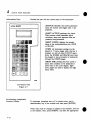
Control Panel Operation
Basic Description
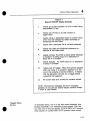
Main Menu Keys
Understanding the 9100/CP Menus
Entry Changes
Controlling the Arbitrary Function Generator
with the 9100/CP
Selecting an Arbitrary Waveform
Selecting a Standard Waveform
Selecting Attributes of Standard Sine
Selecting Attributes of Standard Square
Selecting Attributes of Standard Triangle
Selecting Attributes of Standard Ramp
Selecting Attributes of Standard Pulse
Selecting Attributes of Standard DC
Channel 1 WaveformAttributes
Channel 2 WaveformAttributes
Controlling the Tunebase
Trigger Control
Arming and Firing Trigger
Workingwith Setup Files
Workingwith Sequence Files
Loading and Linking Waveforms
Executing Waveforms
Aborting Waveforms
Accessingthe State of the AFG
5 Operating
4-1
4-1
4-5
4-11
4-19
’ 4-22
4-23
4-25
4-26
4--27
4-28
4-28
4-29
4-30
4-30
4-33
4--33
4--37
~ ~0
~ ".0
~ ~2
~ ~3
~ ~5
~ ~5
~ ~5
over the GPIB
Genera]
Introduction
Remote Mode
Local Mode
Addressing
Messages
Device Dependent Messages
Message Input Format
Command Format
CommandParameters
General Rules for Commands
IEEE-488Standard Messages
Receiving the Device Clear Message
Receiving the Trigger Message
5-1
5-1
5-1
5-1
5-2
5-2
5-2
5-3
5-3
5--4
5-5
5-5
5-5
l
TABLE OF CONTENTS
Receiving the Remote Message
Receiving the Local Message
Receiving the Local Lockout Messages
Sending Messages
Sending the Require Service Message(SRQ)
Sendingthe Serial Poll Status Byte
Sending the Secondary Status Bytes
Operation of the Status Bytes
AcronymGuidelines
Programming CommandReference Section
Command Summary
File Handling Commands
File Structures
Setup and Sequence Files
Setup Files
Executing Setup Files
SequenceFiles
Executing Sequence Files
Single WaveformFiles
Dual WaveformFiles
Executing WaveformFiles
File Handling Commands
DELETE
END
LEARN_SETUP
LINK
LOAD
RECAIJ~
SEQUENCE
SETUP
STORE
Action Commands
ABORT
ARBITRARY
ARM
CALIBRATE
CI.FAR
GO
NEXT
SELFTEST
STOP
TRIGGER
Channel Parameter Commands
CH 1 AMPLITUDE(CH2_AMPLITUDE)
CH I"FILTER (CH2_FILTER)
5-5
5-5
5-5
5-6
5-6
5-6
5-7
5-7
5-14
5-15
5-18
5-18
5-19
5-19
5-20
5-20
5-21
5-22
5-22
5-23
5-24
5-25
5-26
5-27
5-29
5-30
5-31
5-32
5-33
5-34
5-35
5-36
5-37
5-38
5-39
5-40
5-41
5-42
5-43
5-44
5-45
TABLE OF CONTENTS
CH l_I NVERT(CH2_I NVERT)
CHI OFFSET (CH2_OFFSET)
CHI__.OLrI~UT (CH2_OUTPUT)
CH I_ZERO_REF (CH I_ZERO_REF)
EXTERNAL SUM
SUM_MODI~
Timebase Commands
CLOCK_SOURCE
CLOCK_LEVEL
CLOCK_MODE
CLOCX_RA~
CLOCK_SLOPE
CLOCKPERIOD
CLOCKREFERENCE
Trigger Commands
DELAY MODE
MARKI~R DELAY
TRIGGEI~ ARM SOURCE
TRIGGER_-DELAY
TRIGGER_LEVEL
TRIGGER_MODE
TRIGGER_SLOPE
TRIGGER_SOURCE
Standard Function Commands
STANDARD
SINE
SINE_MODE
SINE_FREQUENCY
SINE CHI PHASE
SINE_-CH2-_PHASE
5--46
5-47
5-48
5-49
5-50
5-51
5-52
5-53
5-54
5-55
5-56
5-57
5-58
5-59
5-60
5-61
5-62
5--63
5--64
5-65
5--66
SQUARE_MODE
SQUARE_FREQUENCY
5-68
5-69
5-70
5-71
5-72
5-73
5-74
5-75
5-76
TRIANGLE
TRLkNGLE_MODE
TR/ANGLE FREQUENCY
TRIANGLE_PHASE
TRIANGLE_RELATIVE_PHASE
RAMP
RAMP_MODE
RAMP_PERIOD
RAMP_PHASE
5-78
5-79
5-80
5-81
5-82
5-83
5-84
5-85
5-86
5-87
SQUARE
SQUARE_PHASE
SQUARE_P.ELATIVE_PHASE
5-77
TABLE OF CONTENTS I
RAMP_RELATIVE_PHASE
PULSE
PULSE_WIDTH
PULSE_PERIOD
PULSE DELAY
PULSE-OPTIMIZE
DC
DC_MODE
5--88
5-89
5-90
5-91
5-92
5-93
5-94
5-95
Query Type Commands
ACTIVE FILES
FUNCTION
EXIST
DIRECTORY
IDENTIFY
MEMORY
VIEW
5-96
5-97
5--98
5-99
5-101
5-102
5-103
Communication
Commands
COMM_FORMAT
COMM_HEADER
MASK
STB
TSTB
COMMAND SUMMARY
5-105
5-106
5-107
5-108
5-109
5-110
Figure 5.1 - Heirarchical Structure Of The 9100
Status Bytes
Table 5.1 -Status Byte Bit Assignments
Table 5.2 - Error Codes
Table 5.3 - 9100 GPIB Acronyms
6 RS--232-Interface
Selecting the RS-232C Interface
Configuring the RS--232C Interface
Using RS-232
Typical RS-232C Dialog
RS-232 Commands
COMM_RS_CONF
COMM_PROMPT
COMM_RS_SRQ
5-9
5-10
5-11
5-14
6-1
6-1
6-2
6-3
6--4
6--6
6-7
]TABLE OF CONTENTS I
7 Model 9109
GeneralDescription
High Speed Memory
Digital Output Specifications
Reconfiguring the Digital Output
Interconnection Information
Application InformatiOn
9109 Front Panel Diagram
8 Model 9101
Introduction
Differences Between 9101 and 9100
9101 Front Panel Diagram
9 9100/MM, /MM1,/MM2
7-1
7-1
7-1
7-4
7-6
7-10
7-12
8-1
8-1
8-4
Description
9..-1
Using The Control Memory Image Functions
Learning A CMI File
Deleting A CMIFile
Reviewing The Contents ofA CMI File
9--3
9-3
9--5
9-6
U.ing The Memory
Expamion
Option
9--2
10 9100/RT
Introduction
Verifying Installation
Functional Description
9100/RT LOAD and LINK Comands
FIFO Memory Commands
External FIFO Loading
FIFO Reading
F..yamples of Operation
External Real-Time Port
Using the 9100/RT Option
Using the External Real-Time Port
Waveform Selection Using BASICA
Specifications
Appendix I
Index
10-I
10-1
10-2
10-4
1 0-5
10--6
10--8
10-9
10-10
10-11
10-15
10-17
10-19
GENERAl,
1
PURPOSE
"
INFORMATION
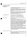
This manual is intended to provide instruction regarding the
setup and operation of the covered instruments. In addition, it
describes the theory of operation and presents other information
regarding its functioning and application.
The Service Documentation, packaged separately, should be
consulted for the schematics, parts lists and other materials that
apply to the specific version of the instrument as identified by
its ECOnumber.
UNPACKING
INSPECTION
WARRANTY
AND
LeCroy recommends that the shipment be thoroughly inspected
immediately upon delivery. All material in the container(s)
should be checked against the enclosed Packing List and shortages reported to the carrier promptIy. If the shipment is damaged in any way, please notify the carrier. If the damage is due
to mishandling during shipment, you must file a damage claim
with the carrier. The LeCroy field service office can help with
this. LeCroy tests all products before shipping and packages all
products in containers designed to protect against reasonable
shock and vibration.
LeCroy warrants its instrument products to operate within specifications under normal use and service for a period of one year
from the date of shipment. Component products, replacement
parts, and repairs are warranted for 90 days. This warranty extends only to the original purchaser. Software is thoroughly
tested, but is supplied "as is" with no warranty of any kind covering detailed performance. Accessory products not manufactured by LeCroy are covered by the original equipment manufacturers warranty only.
In exercising this warranty, LeCroywill repair or, at its option,
replace any product returned to the Customer Service Department or an authorized service facility within the warranty period, provided that the warrantor’s examination discloses that
the product is defective due to workmanship or materials and
has not been caused by misuse, neglect, accident or abnormal
conditions or operations.
The purchaser is responsible for the transportation and insurance charges arising from the return of products to the servicing
facility. LeCroy will return all in-warranty products with transportation prepaid.
This warranty is in lieu of all other warranties, express or implied, including but not limited to any implied warranty of mer-
1-1
General Information
chantability, fitness, or adequacy for any particular purpose or
use. LeCroy shall not be liable for any special, incidental, or
consequential damages, whether in contract, or otherwise.
PRODUCT ASSISTANCE
MAINTENANCE
AGREEMENTS
DOCUMENTATION
DISCREPANCIES
SOFTWARE LICENSING
AGREEMENT
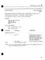
Answers to questions concerning installation,
calibration, and
use of LeCroy equipment are available from the SSD Customer
Services Department, 700 Chestnut Ridge Road, Chestnut
Ridge, New York 10977-6499, (914) 578-6020, or your local
field service office.
LeCroy offers a selection of customer support services. For example, Maintenance agreements provide extended warranty that
allows the customer to budget maintenance costs after the initial
warranty has expired. Other services such as installation, training, on-site repair, and addition of engineering improvements
are available through specific Supplemental Support Agreements.
Please contact the Customer Service Department or the local
field service office for details.
LeCroy is committed to providing state-of-the-art
instrumentation and is continually refining and improving the performance
of its products. While physical modifications can be implemented quite rapidly, the corrected documentation frequently
requires more time to produce. Consequently, this manual may
not agree in every detail with the accompanying product and the
schematics in the Service Documentation. There may be small
discrepancies in the values of components for the purposes of
pulse shape, timing, offset, etc., and, occasionally, minor logic
changes. Where any such inconsistencies exist, please be assured that the unit is correct and incorporates the most up-todate circuitry.
Software products are licensed for a single machine. Under this
license you may:
¯ Copy the software for backup or modification purposes in support of your use of the software on a single machine.
¯ Modify the software and/or merge it into another program for
your use on a single machine.
¯ Transfer the software and the license to another party if the
other party accepts the terms of this agreement and you relin-
1-2
General
Information
1
quish all copies, whether in printed or machine readable form,
including all modified or merged versions.
SERVICE
PROCEDURE
Products requiring maintenance should be returned to an
authorized service facility. If under warranty, LeCroy will repair
or replace the product at no charge. The purchaser is only responsible for the transportation charges arising from return of
the goods to the service facility.
For all LeCroy products in need of repair after the warranty
period, the customer must provide a Purchase Order Number
before any inoperative equipment can be repaired or replaced.
The customer will be billed for the parts and labor for the repair as well as for shipping.
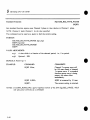
All products returned for repair should be identified by the
model and serial numbers and include a description of the defect or failure; name and phone number of the user. In the
case of products returned, a Return Authorization Numberis
required and may be obtained by contacting the Customer gervice Department in your area.
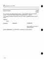
New York Corporate Headquarters
(914) 425-2000 or
East Coast Regional Service
(914) 578-6059
New Hampshire
(603) 627-6303
Virginia
(703) 368-1033
New Mexico
(505) 293-8100
California
(415) 463-2600
1-3
PRODUCT DESCRIPTION
2
9100 SYSTEM
DESCRIPTION
The LeCroy 9100 Series Arbitrary Function Generators (AFG)
are high performance ATEor benchtop instruments which can
generate either standard or user-defined, complex waveforms
with unparalleled point-to-point resolution. They are fully programmable via either GPIB or RS-232. Wavef6rm creation and
editing software is offered for PC-DOScompatible computers.
The products in the 9100 Series are:
9100 high speed dual channel Arbitrary Function Generator
9101 high speed single channel Aribitrary Function Generator
9109 high speed dual channel Arbitrary Function Generator
with digital outputs.The commonelements of the 9100 Series
are described in the early chapters of this manual. Product specific information for the 9109 and 9101 is located in Chapter 7
and 8 respectively.
The 9100 Series instruments are part of a complete custom
waveform generation system. The main products which support
this system are listed below.
9100,
9101, 9109
ARBITRARY FUNCTION GENERATOR MAINFRAME. This
is the basic mainframe unit. The standard unit is remotely programmable over GPIB. This unit has local control ONLY
through use of the optional 9100/CP control panel.
9100R
9100 REAR PANEL CONNECTOR MAINFRAME. Same as
9100 except all signal input and output connectors are brought
to the rear panel.
9100/CP
9100 HAND-HELDCONTROLPANEL. This is the control
panel which adds local operation of all features of the 9100 with
the exception of waveform file creation, editing and downloading. Metal brackets are included to allow control panel to be
free-standing or attached to side of the 9100 mainframe.
The EASYWAVE®
Operating
products:
Manual covers
the following
9100/SW
EASYWAVE
SOFTWARE.An optional
software
package for
PC-DOScompatible computers which provides easy waveform
creation and editing. This includes creating waveforms from a
simple waveform element library, equations, tabular editing, or
direct acquisition from LeCroy Oscilloscopes. Without this
package waveform files must be created on a host computer
either with a text editor or a user written program and then
downloaded either over GPIB or RS-232.
9100GPIB2
IBM PC COMPATIBLE GPIB CARD AND SOFTWARE. This
GPIB card and driver software are required to run EASYWAVE
2-1
Product Description
from an IBM XT/AT compatible. Manuals are included with
this for detailed operation of GPIB without EASYWAVE.
Operation of the 9100 AFG via the EASYWAVE
software package provides full capability without compromise. All waveforms
may be edited at any time and the 9100 can be operated via a
full-screen interface on the host IBMXT/AT.
NOTE:Waveform editing capability
the 9100 Series mainframe.
has not been provided in
Some applications may not need to have waveform creation or
editing facilities on hand at all times. In these cases, after the
waveforms have been created with EASYWAVE
(or other user
supplied program) and downloaded to the AFGnon-volatile
RAMdisk the host computer may be disconnected and the
AFGcan be used as a "custom" waveform generator with all
control accessible via the 9100/CP control panel.
Some users may need to use other host computers to operate
their test systems. In this case the basic waveformshapes
needed for testing may be edited using EASYWAVE
and downloaded into the 9100 or transferred to the test system host computer.
9100 WAVEFORM
GENERATION CONCEPT
The 9100 is a signal source whose output voltage as a function
of time .can be programmedvia an array of data values and
various control settings. The instrument generates the waveform
by sequentially steppir~g through the array and outputting a voltage proportional to each data value for a fixed time interval or
sample period (point). Selecting or specifying the contents
the data array are performed separately from entering the control settings commandsso the user has a great deal of flexibility
in modifying a waveform without having to change its basic
shape (the waveform data array).
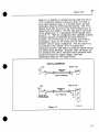
A simple way of thinking about the operation of an AFGis
shown in Figure 2.1. Basically, an oscillator clocks a counter
which in turn advances the address applied to a memory. The
memorydata value which is stored in the next sequential location is then output to the digital-to-analog
converter (DAC).
Finally the DACconverts the data value to an analog level. As
the counter steps through the memoryaddresses, the associated
data values are converted by the DAC. This results in a voltage
waveform being output which is proportional to the data array
which resides in the memory.
2-2
Product
2
Description
SIMPLIFIED AFG
RAM
COUNTER
ADDRESS
DATA
DAC
~
WAVEFORM
OUTPUT
Figure 2.1
The 9100 can emulate standard types of generators without the
use of a host computer to edit the data arrays. The available
standard waveforms are sine, square, triangle, ramp, pulse and
DC.
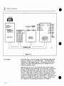
9100
ARCHITECTURE
The 9100 Series mainframe and CP is most easily visualized
four main blocks (Figure 2.2):
1.
2.
RAM DISK
INSTRUMENT
3.
CONTROL PANEL
4.
WAVEFORM GENERATOR CIRCUIT
in
CONTROL
2-3
Product Description
BATTERIES
( REARPANEL)
35OK BYTE
NON’VOLATILE
STORAGE
USER DEFINED:
¯ WAVEFORM
FILES
SETUP FILES
SEQUENCEFILES
RAMDISK
~........................../
1
RS232
LeCroy
91001CP
EXT TRIG
CLK I OUT
MANUALTRIG
CLK2 OUT
SUM
8YNC
EXT CLK
GPIS
EXT REF
START
MARKER
CH I OU1
CH 2 OUT
r-, CI D I~ I’~
0rZ_,
0,D,_-I
REMOTE
CONTROL
:, ~ I:l i’ll_ I=l 1:7
i_~,~~_~_,-,
WAVEFORM
GENERATOR
CIRCUITS
BNC
CONN
,..~ I-, O.Ci ,-,
1
INTERNALBUS
B-IOII
Figure 2.2
RAM DISK
The RAMdisk is used for storage of the waveform data arrays
which are referred to as "waveform files".
The RAMdisk is
350Kbytes of non-volatile storage. All waveform files must be
stored in the RAMdisk before they (~an be loaded into the
waveform generator circuit.
Depending on the size of the waveform files and the number
that are needed on the RAMdisk at any one time, all files may
be kept on the RAMdisk so they don’t have to be reloaded
every time they need to be generated or when the unit is powered on. Other types of files are used for automating the setup
of waveform data and waveform control settings, these are referred to as "sequence files" and "setup files". All standard file
handling commandsare available such as delete, directory, etc.
For summary of file handling commands see Chapter 5,
2-4
Product
INSTRUMENT
CONTROL
CONTROL PANEL
WAVEFORM
GENERATOR CIRCUIT
Description
2
All functions of the instrument are accessible remotely via either
GPIB or RS-232. All details of operation over GPIB are located in Chapter 5 of this manual. The commandsyntax and
operation over GPIB and RS-232 are identical with a few exceptions outlined in the section covering RS-232.
Once arbitrary waveform files are transferred into the RAMdisk
via the GPIBinterface or the RS-232, all other operations can
be controlled locally from the control panel. This includes loading waveforms from the RAMdisk into the Waveform Generating Circuit, setting all waveformattributes and executing "sequence files" and "setup files" as well as accessing status summaries. Operation of all standard functions are supported via
the 9100/CP control panel. For complete instructions
on operating via the control panel refer to Chapter 4.
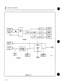
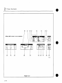
This is the block which takes the waveform files and converts
them into an analog waveform. Brief block diagrams are shown
in Figures 2.3 and 2.4. The five main subcircuits are the trigger, time base, waveform memory, digital-to-analog
converter,
and signal conditioner.
An understanding of some of the internal architecture will help
explain the response of the analog output to various combinations of output amplitude and offset while in different operating
modes.
Refer to the signal conditioning section of Figure 2.4. Under
ideal circumstances the 9100 will choose the post-amplifier attenuators to achieve the requested amplitude. This allows the amplifier to produce large swings. The post amp attenuators attenuate all three aspects of the signal: the signal itself, the offset and
any background noise. To offer extra versatility,
there are preamplifier attenuators which may be selected in lieu of or in addition to the post-amplifier attenuators. The preamplifier attenuators attenuate only the signal; any offset or background noise
of the amplifier is not attenuated. Whenusing the preamplifier
attenuators to accommodatelarge offsets, the apparent Signalto-Noise ratio of the output may decrease slightly.
Amplitude always refers to the peak-to-peak swing at the output
for a digital change of 255 counts in a waveformfield. Offset is
the voltage level that will be output when a digital value equal to
the ZREFlevel is generated by a waveform file. In the following
text ideal calibration of the analog circuits is assumed. In actual
9100 units, the internal calibration will create transitional points
which may differ from the exact values discussed below. This is
normal.
2-5
Product Description
If there is a conflict in requested amplitude and offset settings,
the 9100 always tries to achieve the requested amplitude in preference to the requested offset. A general guideline relating
maximumoffset to requested amplitude is that you can always
achieve an offset of between 8 and 16 times the requested amplitude as long as all points of the waveformare within the
4-5 V limitation (assuming a 50 12 load) of the output amplifier.
To calculate the exact value of maximumoffset achievable for a
given amplitude you first divide the requested amplitude into
10 V. This gives you the total attenuation factor that is required. If this value is less than 32 then the achievable output
levels will be anywhere within the 4-5 V range. For attenuation
factors greater than or equal to 32, divide the required attenuation factor by 32 and choose the next higher power of 2 than
the result. For example, if the division yields a result of 11.32
the next higher power of 2 would be 16. This power of 2 is the
least amount of post-amplifier that will be utilized up to a maximumof 64 (2^6). The maximumachievable output level
4-5 V divided by post-amplifier attenuation.
In requesting an offset value you should be aware that any point
of the output waveform which exceeds the achievable output
levels due to the combination of amplitude, offset and ZREF
will generate an error message. A clipped or distorted output
may also result from exceeding the maximumoutput levels.
NOTE:The amplifier will appear to operate, with reduced performance, for levels up to 125% of the calculated maximum
levels.
When the 9100 detects an output programming which exceeds
the maximumlevels an warning code of 202 is set into STB4
and bit 4 of STB7(a warning) is set. The facts described above
can be quickly understood with the following example. Start by
generating any convenient waveform with the 9100 and set the
offset to 4.8 V and ZREFto 127.5. Set the amplitude to 10 V.
Clearly the top half of the waveform is cutoff or clipped due to
the limitation of the amplifier and an error message has been
generated. Reduce the amplitude to 1 V. The output will appear
correct since the amplifier has some usable range beyond the
5 V limitation described above, but an error message will again
be generated. Further reduce the amplitude to 330 inV. At this
point the offset to amplitude ratio is near the maximumachievable value of 16.
A reduction in the requested amplitude to 300 mVrequires additional post-amplifier attenuation. As a result, the 300 mVamplitude request will allow for only a 2.5 V offset even though
the unit has been requested to generate a 4.8 V offset. An error
2-6
"
Product
Description
2
message will be generated. Also at this point the amplifier is
being driven well above its 25%safety margin and the output is
fully saturated; no visible signal appears, only insufficient offset
is perceived. The unit will not indicate the erroneous offset
value if queried, but instead returns the requested offset value.
If the requested amplitude is changed back to 330 mV, then the
9100 will again generate 4.8 V of offset. As a final example, if
the requested amplitude is 40 mV, then the maximumachievable offset is 625 mV.
Similar concerns apply to attenuator selection when sum modes
are utilized. Whenexternal sum mode is selected, the sum signal is injected at the input of the output amplifier. To avoid
attenuating the external sum signal, the 9100 chooses to use the
preamplifier attenuators in preference to the post-amplifier attenuators. This tends to cause a slight reduction in signal-to-noise
ratio. However, when the requested amplitude for the internal
generated signal is less than 312 mV, some post-amplifier attenuators are required. This causes the external portion of the
summedsignal to be attenuated.
NOTE: No error message is generated.
The 312 mVcomes from the fact that the pre-amp attenuators
offer an attenuation factor of 16 and the fine gain control of
the Signal DACoffers a factor of 2 for a total attenuation of 32
without using the post-amplifier attenuators. 10 V divided by 32
equals 312.5 mV.
When the two channels are summed, the summing is dgne at
the preamplifier point of the circuit. To be certain that the correct gain will be applied to each channel’s contribution to the
summed’signal you should verify that both channels’ amplitudes
can be generated with the same amount of post-amplifier attenuation. This typically limits the ratio of the two channels’
amplitudes to a value between 16 and 32. A safe method is to
limit the ratio of the two channels’ amplitudes to less than or
equal to 16. If this is not done, then the amplitude contribution
of the lower amplitude channel will be greater than programmed.
2-7
Product
I
Description
EXT TRIG
INPUT
~..
I
_1__
(MANUAL
~ oo
~
IsELEcT
INPUT
,I
~
[
TRIG I
~H
/
I
~1
OUTPUT
z
]
~~
COMMAND
OUTPUT
1
TRIGGER
EXT CLK
INPUT
I
START
tN PUT
I 1
i
MASTERCLOCK
SYNTHESIZER
IMHz - 20OMHz
-’
I CLKOUT,
I
I O~TPOT
I
Figure 2.3
2-8
STOP
TI
END OF
WAVEFORM
TI MEBASE
v GATED
CLOCK
MASTER
CLOCK
GATE
CLK OUT2
OUTPUT I
B-IOI2
Product
Description
2
Figure 2.4
2-9
Product
Description
LaCroy9100 ARBITRARY FUNCTION
"
GENERATOR
II
HAN
I
¯ UM1"2
CHAN
I I Ill
B-1004
Figure 2.5
2-10
Product
2
Description
FRONT PANEL CONTROLS,
CONNECTIONS AND
INDICATORS
[] Power Switch Rocker switch that turns AC power on or off.
LEDabove switch indicates power is on.
[] Manual Trigger Pushbutton: Will cause a single shot trigger when pressed, if it is enabled via trigger source selection. If
held down it will cause continuous triggers at a rate of about 2
per second.
[] ArmedLED: Indicates trigger is armed, that is, if a trigger
is received on an enabled trigger source the waveform will be
output. Meaningful only if 9100 is "in a triggered mode (not
free-running) and a waveform is active.
[] GPIB Status
LED’s
Talk: Indicates 9100 is currently addressed to talk.
Listen: Indicates 9100 is currently addressed to listen.
SRQ: Indicates
STATUS LED’s
9100 is asserting
[] Waveform Active LED: When lit,
loaded and running.
SERVICEREQUEST.
indicates
waveform is
[] CHAN1 or CHAN2 invert LED’s: The waveform for the
indicated channel is inverted if one of these is lit.
[] Self-Test Controls: The self-test
is performed automatically
on power-up, and can be invoked at any other time by pressing
the pushbutton to the right of the self-test LED. The self-test
LEDis lit when the Model 9100 is performing the self-test.
If
the self-test procedure identifies a fault the test-fault LEDwill
flash temporarily. If the test fault LEDis lit steadily, it indicates that the 9100’s CPUhas stopped functioning.
[] Battery Low LED: Indicates
when the RAMdisk back-up
battery is low. Whenthis LEDis lit, the batteries should be replaced by an equivalent pair of 3 V lithium cells.
[] Local LED: When lit means the 9100 is being controlled
via the 9100/CP control panel or RS-232. When off, the 9100
is capable of responding to commands from GPIB. The 9100 is
in the local state on power-up.
[] Waveform Output Status
LED’s
CHAN1: Indicates waveform being output on Channel 1. When
blinking an overload has occurred. The overload can be cleared
by enabling the channel’s output.
CHAN2: Indicates waveform being output on Channel 2. When
2-11
Product Description
blinking an overload has occurred.
SUM1+2: Indicates that the 2 channels of a dual waveform are
being summedand output on Channel 1 output. A flashing indication is caused by an overload on the External Sum input. An
overload can be cleared by reasserting
the Sum On command.
Input/Output
Connectors
[] Keypad Connector: The cable from the 9100/CP plugs into
this connector.
[] CHAN1 Waveform Output: BNC connector for Channel 1
output. Active when either CHAN1 LED or SUM1+2 LED is
lit.
[] CHAN2 Waveform Output: BNC connector for
output. Only active when the CHAN2 LED is lit.
Channel 2
[] SUM(CH1): Input connector for summing an external
analog signal in with the signal being generated on Channel 1.
The external sum input must be enabled using the XSUMcommand or selection on the 9100/CP.
[] TRIGGER/GATE:
External trigger or gate input connector.
Acts as trigger or gate input depending on trigger mode selected.
[] MARKER:Timing pulse which can be programmed to be
output in the range from 2 to 1 million clock cycles after receipt
of trigger. The marker output is functional only in Single, Burst,
or Recurrent trigger modes. Note that if the Marker delay is
programmed for a number greater than the sum of the trigger
delay and the total number of points that will be output (including segment repetitions, links, and waveform repetitions), no
Marker pulse will be generated. Also, at clock rates greater than
10 MHz, the width of the Marker pulse (nominally 100 nsec)
maybe reduced if it is positioned within 100 nsec of the last
point generated.
[] START:Timing pulse which is output at the beginning of
each iteration of the waveform.
[] SYNC:Is a pulse that occurs approximately 2 clock cycles
after receipt of trigger and is synchronized to the selected clock
source.
2-12
Product
Description
2
REAR PANEL CONNECTIONS
AND CONTROLS
[] Batteries: This compartment contains 2 Lithium batteries
for powering the RAMdisk memory. The compartment door is easily opened for
battery replacement.
[] GPIB Connector: Standard IEEE-488
connector.
[] RS-232: 25 pin DIN (panel mounted female) connector.
[] GPIB Address Configuration
Dip-switch:
The right-most 5 switches (bits) are used
set the address. Note the LSB is marked and
is the rightmost bit. A switch in the up position is a I and in the down position a 0. The
sixth switch from the right is used to specify
whether the 9100 powers up with the GPIB or
RS-232 as the default active interface. The
last 2 switches are unused.
[] RS-232 Configuration Dip-switch:
This switch is used to set up the RS-232
parameters.
[] AC Power Connector: IEC type.
[] 115 V FUSE: Used only for
operation. 3A fuse required.
115 V
[] 220 V Fuse: Used only for 220 V
operation. 1.5A fuse required.
@
Figure 2.6
[] Line Voltage Selector Switch: This
switch should be properly set before inserting line cord into power receptacle.
Upper position for 115 and lower position for 220.
[] 9100R BNC Mounting Holes: In
the Model 9100 the blank holes are
covered with metal plugs. In the Model
9100R, the normal front panel signal
BNCconnectors are located here and a
special front panel without connectors is
mounted.
2-13
Product Description
[] CLOCKIN REF: A 4 MHzreference oscillator,
amplitude
between 1 and 4 V p-p, may be used as the 9100 reference
oscillator instead of the internal crystal. It is input here and the
signal is ACcoupled.
[] CLOCKIN EXT: The internal
synthesizer
may
be bypassed altogether and the 9100 can be driven by a clock
signal that is input to this connector. This input is selected via
the CLOCKm SOURCE command.
[] CLOCKOUT1: Ungated clock output at the point rate for
single channel waveforms, or twice the point rate for dual channel waveforms.
[] CLOCKOUT 2: Gated clock output
eration.
2-14
for master-slave
op-
Product
2
Description
SPECIFICATIONS
WAVEFORM OUTPUTS
Channels:
2
D.C. Accura.cy: 1.0% of level or 1.0% of Full Scale amplitude
or 20 mV(whichever is greater).
Resolution: 8 bits (256 levels).
Dynamic Range: Single or dual channel - 8 bits; Channels
summed- 9 or more bits, depending on wave shape, filtering,
offset requirements.
Total Harmonic Distortion:
< -50 dBc for output frequency of
1 MHzor less. < -35 dBc @ 10 MHz, Typically < -38 dBc @
10 MHzfor output levels < 5V p p
Spurious and non-harmonic distortion:
<-65 dBc, f < 1 MHz
<-60 dBc, f > 1 MHz
excluding the band within
1 kHz of carrier.
Intermodulation distortion:
Two tone intermodulation (CHI:
10 MHz, 1 V p-p; CH2:10.25 MHz, 1 Vp p, summed
mode) typical -58 dBc 3rd order; -70 dBc 5th order.
Signal to Noise Ratio:
Full Scale Amplitude S/N
~45 dB
75 mVor greater
40 dB
30 mV
5 mV
25 dB
S/N specified at 0 V offset, sum mode off.
MaximumOutput Voltage: 10 V p-p (4- 5 V) into
V p-p into high impedance.
Minimum Output Voltage:
5 mV p-p into
50 fl.
Risetime: <5 nsec, 10% to 90% (no filter)
Overshoot and Ringing: 5% of p-p amplitude,
of p-p amplitude, typical
Settling Time: 20 nsec to 3% for 5 V transition,
risetime (filters off).
Offset:
Individually
Offset
Resolution:
Offset
Accuracy: Same as D.C. accuracy
50 11,
maximum; 3%
including
programmable for each channel.
< 6 mVsteps
2-15
Product Description
Maximum Offset Voltage:
External Load:
Max. Offset V:
50 n
4-5 V
Open Circuit
4-10 V
Output Smoothing: Built-in filters with programmable cutoff
frequencies: bypassed, 1, 3, 10, 30, 100 MHz; 18 riB/octave
(Bessel)
Crosstalk between channels: < I%
Internal Summing-I-.5 nsec
Ch I to Ch 2 Phase Accuracy:
Dual Outputs 4-1 nsec
STANDARD FUNCTIONS
(WAVEFORMS)
Sinewave Squarewave
Triangle
-
Frequency Range: 0.01 Hz to 25 MHz
Frequency Resolution: 0.035%
- Frequency Range: 0.01 Hz to 100 MHz
(50 MHzdual channel)
Frequency Resolution: 0.035%
Frequency Range: 0.01 Hz to 25MHz
Frequency Resolution: 0.035%
Linearity: 4-1%
Pulse - (single channel only) Period: 40 nsec to
variable, 5 nsec to 10 sec (not to exceed period);
selectable, positive or negative going.
Ramp- Period: 40 nsec to 100 sec; Resolution:
Linearity:--1-1%; Orientation: selectable, positive
ing.
10 sec; Width:
Orientation:
0.035%;
or negative go-
DC- Generates a D.C. level, the value of which is the offset
level. Accuracy: the greater of 1% or 20 mV.
TIME BASE (Clock
Rate)
Range: 5 nsec to 20 sec per point
Resolution:
0.035%
Accuracy: 5 ppm, at achievable set points, 230 C,
115 VAC/60 Hz, after 30 minute warmup
Stability:
< 0.5 ppm/° C
TRIGGER
Modes
2-16
Continuous: The generator runs continuously at the selected
frequency.
Product
2
Description
Recurrent: The waveform is cycled with a programmable delay
of up to 1 million points (1/2 million in dual channel) between
cycles. Number of waveforms per cycle is programmable up to
65,535.
Single: Upon receipt of a trigger, the selected waveform is generated only once. The start of the waveform can be delayed
from the trigger point by up to 1 million points (1/2 million in
dual channel).
Burst: Upon receipt of a trigger, the selected waveform is generated the number of times set into the burst counter, up to
65,535. The start of the burst can be delayed up to 1 million
points (1/2 million in dual channel).
Gated (uses the trigger threshold): Uses a triggered start and
stops at the completion of the current waveform cycle after the
gate closes.
External
Trigger
Threshold:
Source
Slope + or Range-4-2.5 V
Resolution 20 mV(8 bits)
Manual
Front-panel
External
External trigger applied via a front panel BNC
Trigger from GPIB, RS-232 or Control Panel
Bus
button
Control Panel Trigger Key
Auto - Automatically rearms itself.
Arm Source:
Bus - Rearmed from the GPIB, RS-232 or the
Control Panel.
Trigger sources and arm sources may be individually enabled or
disabled.Internal triggering is automatically selected in continuous or recurrent trigger modes
Delay: Variable, from four to one million points (2 to 1/2 million in dual channel).
WAVEFORM
MEMORY
Fast Memory Length: Single Channel - 64 Kpoints;
Channel - 32 kpoints each channel.
Storage Memory Length (RAMDisk):
waveforms, setup and sequence files.
RAMDisk to Fast
byte.
> 350 Kpoints
Dual
for
Memory Load Rate: 250 msec +0.7 l~sec/
2-17
Product Description
Battery back-up:>3 years (non-rechargable Lithium cells).
Minimum Waveform Length: Nonlinked waveform segment, no
looping - 8 points (4 points for each channel in dual mode);
linked waveforms - Single channel operation - 72 points, Dual
channel operation - 36 points for each channel.
Waveform Length Resolution: Single channel operation
point blocks, Dual channel operation - 4 point blocks.
Waveform Loop Counter: One counter
maximumrepetitions
- 4095.
per linked
- 8
waveform
OUTPUTS:
Protection: Waveformoutputs are protected against applied
voltages to 4-40 V. If an externally applied overvoltage condition is detected, the output relay is opened, the LEDfor that
channel is flashed and, if enabled, an SRQis generated on the
GPIB. The condition can be cleared by reconnecting the channel’s output.
Front Panel:
Waveform Outputs - Output impedance, 50 12; All Timing
Outputs - Output impedance, 50 12, source 1.5 V peak into
50 12, approximately 75 nsec duration.
Time Marker Output - Settable from two up to one million
clock cycles, referenced to the trigger point.
Sync Output - Occurs at the next Sample Clock edge after
receiving a trigger.
Waveform Start
Output - Occurs at the start
of the waveform.
Rear Panel:
Clock Outputs - 0 to -0.8 V into 50 12. Approximately a
square wave. Present in all modes including External Clock.
INPUTS
Protection: The maximuminput voltage level for all inputs
should not exceed 5 V.
Front Panel
External
Gate/Trigger
Input - Impedance: 50 12
Sum Input - Impedance: 50 12. Overload is indicated by flashing Sum 1 + 2 LED. Gain: X 1, 4-5% for >350 mVfull scale
output ranges. Bandwidth: >80 MHz at 3 dB
Hand-Held Keypad (Control Panel) Input - DIN co nnector is provided for attaching the hand-held control panel and
display.
Rear Panel
2-18
External Clock Input - Whenthis input is selected, the internal clock is deselected and the waveform is generated using the
Product
2
Description
external clock. Impedance: 50 12 Threshold: Variable -4-2.5 V,
8 bits resolution.
External Reference Input: Selection of this input causes the
internal clock to phase lock to it. It requires a 4 MHzsignal
with 1 to 4 V p-p amplitude into 50 12, AC coupled.
2-19
Product Description
FRONT-PANEL
INDICATORS AND
CONTROLS
Controls
Power ON/OFF
Manual Trigger Button
Manual Self Test Button
Hand-held Control Panel (optional)
Indicators
Power on LED - ON when power is applied to the instrument.
Trigger Armed LED - ON when awaiting a trigger signal.
Waveform Output LED’s: Chan 1: ON when Channel 1 is
turned on; Chan 1 & 2: ON when Channel 1 is being summed
with channel 2. Chan 2: ON when Channel 2 is turned on.
Waveform Active LED: ON when a waveform is being clocked
out of the fast memoryto one or both waveform outputs or if
the unit is armed and waiting for a trigger.
GPIB: Talk LED - ON when the instrument
mode.
is in the talk
Listen LED- ONwhen the instrument is in the listen
mode.
SRQ LED - ON when the SRQ line is asserted and the
instrument is awaiting action from a GPIBcontroller.
Remote - This word is spelled out in the hand-held
control panel display whenever the instrument is put into
remote by a GPIB controller.
Local LED- Located with the keypad input connector,
it indicates when the instrument is in the LOCAL
mode
and the hand-held control panel is operative. Whenit
is not ON, the instrument is in the GPIBremote state.
Self Test LED- ONwhen a self test or calibrate is in progress.
Test Fault LED- Flashes for 10 seconds when a self test or
calibrate determines there is a fault or steady ONin the event
of a microprocessor failure.
Battery Low LED - ON when the RAMDisk memory backup
battery is too low.
Chan 1, Invert LED - ON when Ch 1 output is inverted.
Chan 2, Invert LED- ON when Ch 2 output is inverted.
2-20
A
Product
REAR PANEL
CONNECTORS
SWITCHES
GENERAL
2
AND
Connectors: GPIB: IEEE 488-1978 compatible; RS-232 Port:
DB 25 S Connector.
Switches: GPIB Address Switch; RS-232 Port Configuration
Switch, Line voltage selector and fuses.
WAVEFORM CREATION
AND EDITING
INSTRUMENT
Description
CONTROL
LeCroy’s EASYWAVE®
software package is available for PCDOScompatible computers*. It provides for waveform creation
and editing in a menu driven environment. Waveform creation
can be accomplished by any of the following methods:
1. Equation entry.
2. Selecting and combining simple waveform elements.
3. Waveforms can be acquired over the GPIB from
LeCroy Oscilloscopes and then edited.
Editing may be accomplished as follows:
1. Modifying individual points from the keyboard.
2. Modifying the equation describing the waveform.
3. Deleting, moving and rescaling blocks of data.
* Minimumhardware configuration
of host computer 640K
RAM, 10 Mbyte Hard Disk, Graphics (CGA,HGA, or EGA)
Display.
Other GPIB Compatible Controllers:
Waveforms can be created and edited on other controllers using user supplied software.
PC-DOS Compatibles: The same software package used for
waveform editing also can be used for controlling the 9100.
Local Control Panel: Once the waveforms have been loaded to
RAMDisk, an optional, detachable control panel with a four
line LCDdisplay may be used for controlling the 9100.
Other GPIB or RS-232 Compatible Controllers:
Other computers or terminals may be used to control the instrument using
the remote commands.
GPIB Interface
Functions: IEEE 488-1978 compatible.
SH1,
AH1, T5, TE0, L3, LEO, SR1, RL1, PP0, DC1, DT1, CO
GPIB DMARates: Typically >__200 kbytes/sec
RS-232C: Implemented as data communications Equipment
(DCE).
2-21
Product Description
Baud Rates: 300, 600, 1200, 2400, 4800, and 9600.
Data Bits: 7 or 8.
Stop Bits: 1 or 2.
Parity: None, Even, or Odd.
Protocol: rFull Duplex, Xon/Xoff (DC1/DC3) handshake,
Data Formats: #I Arbitrary length ASCII #L ASCII HEX"00"
to "FF" (double the length of internally stored binary data files)
Commands: Full Conversational
same as GPIB plus: RS_SRQ,
Define character equivalent to SRQin GPIB. Default is "Bell",
ESC commands ECHOon/off Trig remote/local
Temperature Range: 15o C. to 35o C., full specification;
0° C.
to 40o C., operating.
Humidity: 40o C., 10% to 95% relative,
non-condensing.
Power: 115/220 +/- 20% VAC,47-63 Hz. approximately
147 watts
Size: 5-1/4" H X 19" WX 15" D.
Weight: 26 lbs. (approximately).
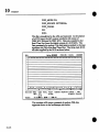
STANDARD ACCESSORIES I each Operator’s Manual
ORDERING
INFORMATION
9100
9100R
9101
9109
OPTIONAL ACCESSORIES
Dual Channel Arbitrary Function Generator
Dual Channel Arbitrary Function Generator with
Rear Panel Connectors
Single Channel Arbitrary Function GeneratOr
Dual Channel Arbitrary Function Generator with
Digital Word Outputs
9100/CP
9100/EC
9100/OM
9100/SM
9100/SW
9100/SP
9100/MM
9100/MM1
9100/MM2
9100/RT
9100 GPIB2
DC/GPIB-2
Detachable Hand-held Control Panel
6’ Extender Cable (Control Panel)
Operator’s Manual
Service Manual
EASYWAVESoftware
Advanced Waveform Creation Software
Waveform Memory Expansion - 1/2 Mbyte
Waveform Memory Expansion - 1 Mbyte
Waveform Memory Expansion - 2 Mbyte
Real-Time Waveform Selection
GPIB Interface Card and Software (National
Instruments PCII Card and GPIB-PC Software)
GPIB Cable, 2 meters
EASYWAVE®
is a trademark of LeCroy Corp
® is a registered trademark of International
IBMXT/AT
Machines Corp
2-22
Business
[OPERATIONS
3
PREPARATION
FOR USE
OPERATING
ENVIRONMENT
Voltage Selection
Fuse Check
The Model 9100 should be operated only within the following
environmental limits:
Temperature: 15°C to 35° C, in spec;
0°C to 40° C, in operating.
Humidity: 40° C, 10% to 95% relative,
non-condensing.
Specifications are rated from +15° C to +35° C.
and
The Model 9100 has been designed to operate from either a
115 V or 220 V nominal power source. On the rear panel of
the instrument, a switch permits user selection of either voltage.
Also on the rear panel, separate fuses are provided for each
voltage.
Prior to powering up the Model 9100, make certain that the
voltage selector switch is set to whichever of those two voltages
corresponds to the available power supply and that the fuse for
that voltage is intact and properly installed.
CAUTION:The Model 9100 will fail to operate and could be
damaged if plugged into a voltage other than that which the
voltage selector switch on the rear panel is set. Thus, correct
line voltage selection MUSTbe made before plugging the
instrument in or turning it on.
Power Cable
The Model 9100 has been designed to operate from a
single-phase power source with one of the current-carrying
conductors (neutral conductor) at ground (earth) potential.
Operation from power sources in which both current-carrying
conductors are live with respect to ground (such as
phase-to-phase on a tri-phase system) is not recommended.
The instrument is provided with a three-wire electrical cable
containing a three-terminal polarized plug for line voltage and
safety ground connection. The plug’s ground terminal is
connected directly to the frame of the unit. For adequate
protection against electrical hazard, this plug must be inserted
into a mating outlet containing a safety ground contact.
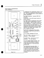
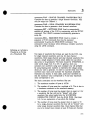
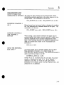
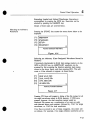
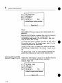
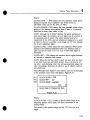
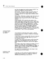
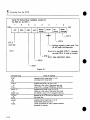
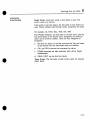
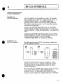
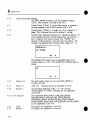
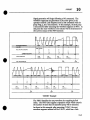
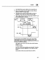
GPIB Address Selection
The Model 9100’s 8-segment GPIB address switch is located
the instrument’s rear panel. Segments 1 and 2 are unused.
Segment 3 selects the communication source. A "1" selects
GPIB and "0" selects RS-232.
on
3-1
Operations
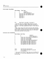
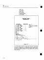
Segments 4 through 8 on the switch
selection as shown in Figure 3.1.
are used for GPIB address
1 = GPIB, 0 = RS-232
GPIB Address
¯
O OOOOOO
0r
o
16 8 4 2 1
For Example:
0 0 0 0 0 = 0
0 0 0 0 1=1
BinaryEquivalent
Not a valid address
automatically
defaultsto 1
Thedefault address
1 0 0 0 1 = 17 Typical Address
Not a valid address
1 1 1 1 1 = 31 automatically
defaults to 1
Valid Addresses
are 1 through30
Figure 3.1
GPIB Selection
and Addresses
RS-232
Power-On
Switch
Setup
Procedure
Refer to Chapter 6.
As described in the preceding sections, the first steps in
operating the Model 9100 is to be sure that it is properly
connected to line power, that it is properly fused, and that the
selector switch on the rear panel is set to the same voltage as
line power.
Once those steps are complete, press the power switch (in the
upper right corner of the front panel) to the ON position.
The
LED above that switch will light to indicate that power is on.
Also on will be the SELF-TEST light in the STATUSrectangle
to the left of the power switch. This light indicates that the
instrument is undergoing calibration,
which is part of self-test.
When the calibration
is complete the self-test
LED will no
longer be lit.
3-2
Operations
3
NOTE:It is normal for all front-panel lights to flash on prior
to self-test.
After calibration, the instrument initializes all control settings,
which takes several seconds. During this time the LOCALLED
will be on. The remote interfaces are ignored until initialization
is complete, to avoid any possible conflicts. After initialization
the message "LECROY9100" appears on the 9100/CP, if it is
attached. If a GPIBcontroller places the instrument in the
REMOTE
state during initialization,
this will be recognized at
the end of initialization.
If the communications source is
RS-232, a prompt "AFG\>" is sent over RS-232 at the end of
initialization.
The instrument is now ready to use in its power-up mode. All
instrument settings will be at their default values and only the
POWERand LOCALLED’s will remain lit (the Model 9100
powers up in LOCALmode, which means it is at that point set
to be controlled by the 9100/CP).
Whensettings are changed to meet the needs of specific
operations, and/or if appropriate commandsare given to invoke
REMOTE
(computer) control of the instrument, different
front-panel LED’s will light up accordingly.
OPERATING THE 9100
In the following sections the general format of remote
commandswill be given to show how certain operations are
invoked. The argument descriptor will often be shown as the
argument name or explanation enclosed in angular brackets.
For example:
Command: CLOCK_PERIOD,<desired period>;
The type of argument is not to be entered literally when the
commandis used. The angular brackets and text enclosed
should be replaced by the properly formatted argument in
accordance with the rules specified in Chapter 5. The argument
is typically a number with a unit appended to it with no
embedded spaces.
All commandsexcept for those that transfer files into and out
of the 9100 can also be given using the 9100/CP via its
menu-driven command entry. See Chapter 4 for the 9100/CP
menu description.
STANDARD FUNCTIONS
Standard functions may be generated with the 9100 using the
9100/CP or by commandover the bus without loading or using
any waveform files. The standard function modes completely
emulate the usual function generator operation by automatically
generating the waveforms needed in the waveform memory. In
3-3
Operations
all these modes the user simply enters the parameters needed
(for example, frequency and phase for sine generation) and the
rest is done automatically.
The standard functions are accessed under the FUNCmain
menu key on the 9100/CP. For detailed instructions
on the
menu driven operation of the standard functions see Chapter 4.
To operate standard functions under remote control, first send
the commandwhich forces the 9100 into the particular standard
function mode (a single word commandwhich is usually the
name of the function, e.g., sine, pulse, ..) and then give the
GO command. The function will then be output. For a detailed
explanation of the operation of all related commandssee
Chapter 5.
Listed below are the commandsfor setting up dual channel
I MHzsine waves with 20° phase difference between Channel 1
and Channel 2,
SINE;
SINE_MODE,DUAL;
SINE FREQUENCY, 1MHZ;
SINE_CH2_PHASE,20;
In standard function modes the clock is set automatically and
cannot be controlled independently as with arbitrary functions.
For this reason all clock related commandsare disabled when in
a standard function mode. Whenusing a 9100/CP, if an
external clock reference is needed in standard function mode it
must be selected when in arbitrary mode and then it will be
active when using standard functions. It cannot be selected
when in standard mode.
ARBITRARY WAVEFORMS
AND FILE CONVENTIONS The LeCroy EASYWAVE
software
running on an IBM XT/AT
computer is the recommended method of creating and
transferring arbitrary waveformfiles to the 9100. The next
section carefully explains how to format and transfer waveform
files to the 9100, and Chapter 5 summarizes all the commands
and formats used. All arbitrary waveforms are handled as files
in the 9100. Once the files exist on the 9100 RAMdisk all
control can be accomplished via the 9100/CP control panel.
All files in the AFGhave an extension which is necessary and
significant. Belowis a summaryof the different types of files
you will encounter. The file name, represented by xxxxxxxx, is
the alphanumeric name that the user gives when creating the
file.
3-4
Operations
3
xxxxxxxx.WAV
- SINGLE CHANNEL WAVEFORM FILE
Contains the data to generate a single channel waveform. May
only be output on Channel 1.
xxxxxxxx.WAD
- DUAL CHANNEL WAVEFORM FILE
Contains the data to generate a dual channel waveform.
xxxxxxxx.SET - SETTINGS FILE Used to automatically
establish all settings of the 9100 in conjunction with the SETUP
command. The LEARNcommand automatically
generates
a
setup file.
xxxxxxxx.SEQ - SEQUENCEFILE Used to contain
a
sequence of 9100 commands that may be executed
automatically
by giving the SEQUENCE
command. This
command is most necessary when defining a complex waveform
using the LINK command.
Defining an Arbitrary
Waveform in Terms
of a Waveform File
Two types of waveform file formats are used by the 9100, one
for single channel waveforms and one for dual channel
waveforms. Both single channel and dual channel waveform files
contain a single sequence of bytes which define the waveform
data array to be generated. The bytes should be UNSIGNED,in
other words range from 0 to 255. In general, when you
calculate your waveform using your computer you will probably
be using floating point numbers to represent the voltage values
which you wish to generate. In order to convert these into 8-bit
waveform data values and maintain the maximumamplitude
resolution you should, in most cases, scale your waveform so
that the minimum value corresponds to 0 and your maximum
value corresponds to 255.
The basic constraints on the waveform files are:
1. The maximum number of bytes is 65536.
2.
3.
4.
The number of bytes must be a multiple of 8. This is due to
a hardware constraint in the waveform memory.
The number of bytes must be greater than or equal to 8 for
a waveform file that will not be "linked" with other
waveform files when loaded into the WAVEFORM
GENERATORCIRCUIT from the RAMDISK. (See page
3-9, for an explanation of waveform file linking.)
The number of bytes must be greater than or equal to 72
for a single-channel waveform file that will be "linked" with
other single channel waveform files. Dual channel files that
are to be linked must contain at least 36 bytes per channel.
3-5
Operations
5, Minimumdata value is 0,
Maximumdata value is 255.The single channel waveform file
simply contains a series of bytes in the exact order in which you
want them to be generated. The single channel waveform will
always be output on Channel 1. The format is given below
where the index specifies the interval (point in time) during
which that value will be generated. The waveform file contains
N data bytes.
a(1) a(2), a(3) a(4) a(5) a(6) ...........
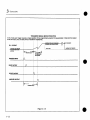
The dual channel waveform file consists of interleaved pairs of
data values which will be routed to Channel l(a) and Channel
2(b). Below we designate bytes for Channel 1 as a and bytes for
Channel 2 as b and the index specifies the interval during which
that value will be generated starting with 1. This waveformfile
contains 2N data bytes and when run will result in N points
being output on channel 1 and N points being output on
Channel 2.a(1)
a(2) b(1) b(2) a(3) a(4) b(3)
a(N-1)
a(N)b(N-1)
TRANSFERRING
WAVEFORM
DATA FILES INTO THE
AFG RAM DISK VIA GPIB
NOTE: If you are using the EASYWAVEProgram to create and
load your waveform files, you may skip this section.
After you have defined the data array which will become your
waveform file, you need to transfer it to the 9100. Wedo this
with the STORE command.
First send the commandto transfer the file.
For single channel waveforms: STOREfilename.wav
For dual channel waveforms~ STOREfilename.wad
NOTE:The extension on the waveform is significant and lets
the 9100 know what type of waveform will be contained in the
file. Filename represents the name by which you will refer to
the waveform file.
Next, send the file. The stream of bytes that you send consists
of either a single block of bytes or a series of blocks. If the file
is being sent in multiple blocks EOI must be asserted only with
the last byte of the last block to indicate the end of the file.
The waveform files may be transferred to the 9100 in either of
two block formats; binary (called #A format) or hex-ASCII
(called #L format). Each individual block consists of a block
3-6
Operations
3
preamble, a count (the number of data bytes in #A and the
number of data values in the #L case). Below are the block
formats for the binary and hex ASCII file block transfers. In
the table, each row corresponds to a byte sent over the GPIBto
the 9100.
3-7
Operations
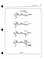
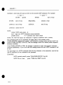
FOR BINARY TRANSFER:
Byte Number
1
#
2
A
3
<data
4
<data
5
<data
<data
6
7
<data
Byte Value
(ASCII#)
(ASCIIuppercaseA)
byte count, most significant byte>*
byte count, least significant byte>*
byte 1>
byte 2>
byte 3>
N+4
<data byte N> (with EOI, if last block)**
* Data byte count is an unsigned integer which in this case
equals N. It contains the number of bytes being transferred in
the block. In this binary representation there is 1 data value per
byte.
**EOI,if sent, must be sent with the last byte. EOI terminates
the file transfer. If EOI is not sent, the 9100 will accept another
block as part of the same file. The last block of a file transfer
must be sent with EOI on the last byte.
FOR HEX ASCII
TRANSFER:
Byte
1
2
3
4
5
6
7
8
9
10
Number
Byte Value
#
(ASCII .#)
(ASCII uppercase L)
L
<value count, 4th hex digit, most significant >*
<value count, 3rd hex digit>*
<value count, 2nd hex digit>*
<value count, ist hex digit, least significant>*
<most significant hex digit of data byte i>
<least significant hex digit of data byte i>
<most significant hex digit of data byte 2>
<least significant hex digit of data byte 2>
<msb hex digit of data byte N>
<lsb hex digit of data byte N> (with EOI,
if no last block)
* Value count is the number of data bytes you are sending over
in this block. In this hex ascii representation there are 2 bytes
per data value.
2N+5
2N+6
3-8
3
Operations
**EOI, if sent, must be sent with the last byte. EOI terminates
the file transfer. If EOI is not sent, the 9100 will accept another
block as part of the same file. The last block of a file transfer
must be sent with EOI on the last byte.
NOTE:Whentransferring files over the RS-232 interface,
last byte must be followed by the character defined by
COMMRS CONF as simulting
EOI; see Chapter 6.
the
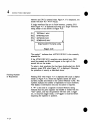
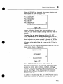
LOADING THE WAVEFORM
FILES FROM RAM DISK
INTO THE WAVEFORM
GENERATOR CIRCUIT
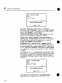
The simplest type of waveform that we can generate is based on
a single waveform file. To generate the waveform described by a
single waveformfile, simply load it and go by issuing the
following commands:
LOADfilename.ext;
GO;
Where ext is either WAVor WAD,if single
respectively.
or dual channel
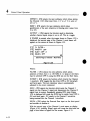
NOTE: The commands shown in this screen are remote
commandsvalid over GPIB or RS-232. All functions are also
accessible from the 9100/CP. Operation with the 9100/CP is
covered in Chapter 4.
If you are using only simple waveforms composed of single
waveformfile, skip the rest of this section of the operation
procedure. The procedure for building up more complicated
waveformswhich utilize the linking and looping capabilities of
the 9100 will now be described.
The waveform data memory length of the 9100 is 64 Kbytes.
This means that if you are using only a single waveform file the
upper limit on a single channel waveform is 64 Kpoints and for
a dual channel waveform is 32 Kpoints per channel. The 9100
provides a way to effectively generate much longer waveforms if
any parts of the waveform are repetitive in nature.
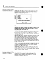
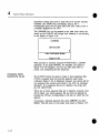
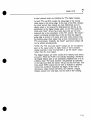
You may link together waveform files when loading into the
waveform memory to define what can be thought of as a
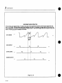
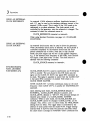
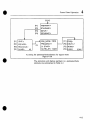
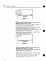
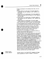
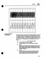
waveform program. Lets look at an example. Suppose you want
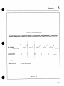
to generate the waveform shown in Figure 3.2. It consists of
several pieces each of which are repeated several times:
3-9
Operations
1
I
4
2
2
6
sine cycle
DC section
since cyles
DC sections
Gaussian pulses
DCsections
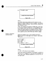
WAVEFORM
LINKING
(SF.OJZ~.E_EU.E)
REPETITIONS
WAVEFORM
SINE L
1
LOAD.SINE
I
T COMP
- OV(10 POINTS)
LINK- T COMP
GAU~L,_
4
-"LINK- SINE
V
IF--LINKr COMP2
2
IIr"-LINK-aAus
6
I[I ILINK - T COMP
Figure3.2
You could simply generate a single data file which contained all
the data as a single array or we provide another method which
will use less waveform memory. We may define three waveform
files as follows:
3-10
Operations
3
contains 1 Gaussian pulse
GAUS.WAV
contains 1 cycle of a sine wave
SINE.WAV
contains a constant data array
T.WAV
We can then load the waveform using the following sequence of
commands:
LOAD SINE.WAV, 1;
LINK TCOMP.WAV, 1;
LINK SINE.WAV,4;
LINK TCOMP.WAV,2;
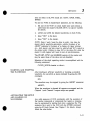
LINK GAUS.WAV,2;
LINK TCOMP.WAV,6;
GO; (when you want to start it running)
The load commandalways comes first and tells the 9100 that
we are loading a new waveform into the waveform memory. In
this waveform the 9100 will generate one repetition of
SINE.WAV, then one repetition
of TCOMP.WAV,
then four
repetitions of SINE.WAV,then two repetitions of
TCOMP.WAV,
then two repetitions
of GAUS.WAV,and finally
six repetitions
of TCOMP.WAV.
When the waveform is loaded
in this manner, as a multi-file waveform, the amount of
waveform data memory used is conserved since each unique file
has to reside in the waveform memoryonly once. Therefore,
the amount of waveform memory used by this waveform is the
sum only of the number of data values in the three files.
Main constraints in making linked waveforms:
1. Minimumsize of each file must be 72 bytes, as opposed to
8 for a single file waveform.
2. A Maximum of 1 Load + 681 sequential
Link commands
can be used to generate a linked waveform.
3. The maximumnumber for the repetition
argument in the
load or link is 4095.
The LINK command also accepts an additional
argument. The
purpose of this argument is to permit each trigger cause output
of different waveform segments.
The format of the command is:
LINKargl [arg2] [arg3];
where optional items are contained in brackets, and items to be
replaced are in lower case.
argl: filename to link, with extension, such as A.WAD.
arg2:
Number between 1 and 4095, inclusive, representing the
segment repetition count. Default if not present is 1.
3-11
Operations
arg3:
WAIT.
The "WAIT"argument, if present, tells the 9100 Series AFGto
wait for trigger before executing this segment. More precisely, it
tells the AFGto act as if the entire waveform ended with the
segment before this one, and this segment is the first one in the
next waveform repetition. A detailed discussion of the effect of
this argument will be found under "Specifying the Trigger
Mode", page 3-15.
3-12
Operations
CONTROL SETTINGS
SUMMARY
(amplitude, clock ....
Channel Parameter
Settings
Specifying the 9100 control settings gives the user control over
the various waveformcharacteristics.
All attributes can be
controlled from the Control Panel as well as by GPIB
commands. The values of the settings determine when a
particular waveform data point will be output and at what
voltage level. The settings can be grouped into the following
major categories shown below.
Settings which control the signal conditioning applied to the
Channel 1 and Channel 2 signals.
CH1 AMPLITUDE
CH 1-OFFSET
CH1 ZERO REF
CH 1-FILTER
CH I_INVERT
CH1 OUTPUT
EXTERNAL SUM
SUM_MODI~
Timebase Settings
3
CH2 AMPLITUDE
CH2-OFFSET
CH2 ZERO REF
CH2-FILTE-R
CH2 INVERT
CH2-OUTPUT
Settings that affect the main clock, which determines the data
point period (i.e., determines rate at which the waveform is
output).
CLOCK_RATE
CLOCK_PERIOD
CLOCK_SOURCE
CLOCK_REFERENCE
CLOCK_LEVEL
CLOCK_MODE
CLOCK_SLOPE
Trigger Settings
Settings that affect when and how the waveform is triggered.
TRIG_MODE
TRIGDELAY
TRIG m SOURCE
TRIG ARM SOURCE
TRIG-SLOP-’E
TRIG LEVEL
MARKER DELAY
DELAY_I~ODE
A detailed explanation of every commandis contained in the
commandreference in Chapter 5.
3-13
Operations
SPECIFYING
HOW THE
DATA VALUES ARE
CONVERTED TO
VOLTAGE LEVELS
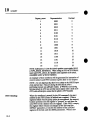
AMPLITUDE, OFFSET AND ZERO REF determine
the output
voltage as a function of data point vaiue, V(n) where n is the
data point value.
NOTE:All voltages are for the output terminated in 50 £). If
the output load is a high impedance, then all voltages at the
output will be 2 × higher than set.
The AMPLITUDE
command sets the full scale voltage range,
that is, the voltage swing obtained when the data point value
changes from 0 to 255. For example the commands to set both
channel amplitudes to 2.3 V would be:
CH1 m AMPLITUDE 2.3V;
CH2 AMPLITUDE 2.3V;
ZEROREF sets the data point value whose output voltage does
not change when the amplitude is changed (think of it as the
fixed point or baseline). This is also the data point value which
when output from the AFGwill correspond to the offset voltage.
This value must fall between 0 and 255 but need not be
constrained only to integer values (127.5 is a valid value and is
the default value for this parameter). The commandsto set
zero_ref to 0 (for unipolar positive operation) are:
CH1 ZERO REF 0;
CH2 ZERO REF 0;
For unipolar positive operation zref is typically set to 0. For
unipolar negative operation zref is typically set to 255.
NOTE:For an autoscaled waveform (i.e., one that is
normalized so that the maximumvalue is 255 and minimum is
O) to be generated symmetrically about 0 V ZREFshould be set
to 127.5, and the offset should be set to 0 V.
OFFSETsets the output voltage obtained when the data point
value is equal to zref. The following commandsset the offset
on channel 1 to 1 V and the offset on channel 2 to 2 V.
CH1 OFFSET 1V;
CH2 OFFSET 2V;
To summarize:
V(n=zref) = Voffset
V(255) - V(0) = Vamplitude
so for a general data point value n:
V(n) = Voffset + Vamplitude*(n-zref)/255
3-14
Operations
3
Where
V(n) is the voltage output for data value n. n is the
waveform data value between 0 and 255. Voffset is the
programmedoffset voltage. Vamplitude is the selected
amplitude voltage. Zref is the selected zero reference point.
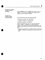
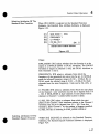
SPECIFYING
PER POINT
THE TIME
The clock period attribute
waveform point is output.
controls the amount of time each
CLOCK_PERIOD
< time value with optional
SPECIFYING THE
TRIGGER MODE
units>;
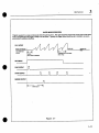
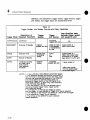
The TRIG_MODE
specifies
the overall running mode of the
waveform. The 9100 has five different trigger modes:
1. Continuous - On receipt of the GO command the generator
outputs the loaded waveform. When it reaches the end of the
waveform it immediately starts over at the beginning with no
interruption between the last point and the first point. The
generator will continue to cycle the loaded waveform until
receipt of an ABORTor STOP. A pulse will be output from the
STARToutput at the beginning of each cycle. The SYNCand
MARKER
outputs are not available in this mode.
COMMAND: TRIG
MODE CONTINUOUS;
m
2. Single (triggered) - This is a single sweep triggered mode.
In general, for each receipt of a trigger the generator will
On receipt of
output one sweep of the loaded waveform.
a GO command the generator
waits for an ARMcommand
(if ARMSOURCE=BUS)before it proceeds. Usually (and
by default)
ARMSOURCE=AUTO,in which case no ARM
is needed. It the~ waits for receipt of a trigger from any
one of the enabled sources. While waiting for a trigger, the
first data point in the waveform is being output. Upon
receipt of a trigger a pulse is output from the SYNC
connector (the output is actually issued on the 2nd positive
clock edge after receipt of trigger). Then the generator waits
a programmed number of clock cycles called the
TRIG DELAY. At the end of the TRIG_DELAYa pulse is
generated at the STARToutput on the front panel. The
generator then outputs the loaded waveform and stops
output, holding the last point if ARMSOURCE=BUS.
In
this case, the output will remain at th~ last point until an
ARMcommand is received.
After the ARMcommand is
detected, the output changes to the first point of the
waveform, and remains in that state until a trigger is
3-15
Operations
received.
If, however, ARMSOURCE=AUTO
(the default
condition), the last point wilt only be held for the rearm
time, and then the output will switch back to the first point
automatically, and the unit will be ready to accept a trigger.
Command: TRIG MODE SINGLE;
3. Burst (triggered) - This is a multiple sweep triggered mode.
It operates identically to the SINGLEmodeexcept that it will
output the programmed number of sweeps of the waveform
instead of just a single sweep.
Command: TRIG MODEBURST,<number of sweeps>;
4. Recurrent - This is basically a BURSTmode with automatic
retriggering. It is a free running mode, not a triggered mode.
When the GO command is given in this mode the waveform will
be cycled until an ABORTor STOPis received. Although it is
free running it is identical in operation to the Burst modewith
two exceptions: (1) no trigger is needed to initiate the
waveform, and (2) the generator is automatically rearmed and
retriggered after every BURSTof waveform sweeps.
Command: TRIG_MODE RECURRENT,<sweeps/cycle>
5. Gate - Gate is a combination of the triggered modes and the
continuous mode. The starting of the waveform is identical to
the triggered modes. The waveform then cycles in a manner
similar to Continuous. When the external GATEinput becomes
inactive the generator will complete the current sweep of the
waveform, stop output, rearm and await the next transition of
the Gate input to the active state. The ARMfeature is not
active (always set to ARM_SOURCE=AUTO).
Command:
TRIGMODE GATE
The "WAIT"argument, if appended to a LINK command, tells
the 9100 Series AFGto wait for trigger before executing the
segment. More precisely, it tells the AFGto act as if the entire
waveform ended with the segment before this one, and this
segment is the first one in the next waveform repetition. This
provides interesting effects, depending on which trigger mode is
selected. It is meant to be used in single trigger mode. The
effects are as follows:
Trigger Mode (TMOD): Effect
Single: A new trigger is required to generate each segment (or
group of segments beginning with one) which has been linked
with "wait". For example, consider:
LOAD A.WAV,1;
LINK C.WAV,2,;
3-16
LINK B.WAV,2, WAIT;
LINK D.WAV, 3, WAIT;
Operations
3
The first trigger will generate only A.WAV
once, because
B.WAV
was linked with "wait". The second trigger will generate
two repetitions
of B.WAVand two repetitions
of C.WAV,
because C.WAVwas linked without "wait". The third trigger
will generate three repetitions of D.WAV.Each trigger generates
appropriate
timing outputs: SYNC, STARTand MARKER,if
possible. The programmed trigger delay occurs following each
trigger.
Continuous: The generated waveform is not affected by links
with wait, since continuous mode never waits for trigger.
However, a STARTpulse is generated at each end-of-waveform
mark, i.e., at the beginning of each segment linked with "wait"
as well as at the beginning of the first (LOADed)segment.
Given the example above, a STARTpulse would be generated
at the beginning of A.WAVand at the beginning of B.WAV’s
first repetition and at the beginning of D.WAV’s
first repetition.
The programmed trigger delay has no effect as usual.
Gated: In this mode, waveform generation is halted at the first
end-of-waveform after the GATEsignal goes false. Each link
with "wait" introduces an end-of-waveform mark. Thus, to
continue the example above, in gate mode generation may stop
just before A.WAV(as normal), or before B.WAV’sfirst
repetition or before D.WAV’sfirst repetition,
whichever comes
first after the gate goes false. Whenthe gate goes true again,
output will begin with the appropriate segment, either A.WAV
or B.WAVor D.WAV,after the programmed trigger delay.
Burst: Burst is very similar to single, except single stops at every
end-of-wave, while burst counts the specified number of
end-of-waves and then stops. So, using the example from
"single" mode once gain, in TMODBURST,3 each trigger
would cause the 9100 to wait the programmed trigger delay and
then produce A.WAVfollowed by two repetitions
of B.WAV,
two repetitions
of C.WAVand three repetitions
of D.WAV.The
three end-of-waveform marks are just before B.WAV,just
before D.WAVand just before A.WAV.
TMOD
BURST,1 is exactly equivalent to single trigger mode,
see above. An interesting modeis to give a burst count that is
neither 1 nor the number of end-of-wave markers in the
waveform. For example, TMODBURST2 would cause
A.WAV, B.WAVand C.WAVto be produced by the first
trigger
(following GO); D.WAVand A.WAVto be produced
the second trigger;
B.WAV, C.WAVand D.WAVto be
produced by the third trigger, etc.
3-17
Operations
Recurrent: Recurrent is the same as burst, with an automatic
trigger immediately occurring whenever the system waits for
trigger.
In summary, in single trigger modethis feature permits the 9100
to produce a sequence of different waveforms in response to a
series of asynchronous external triggers, with as little as 70 nsec
delay from trigger to the next waveform. The trigger may also
be supplied by the TRIG command, but the response will be
slower. In either case, the response is muchfaster than could be
achieved if a sequence of LOADand LINK commands had to
be executed to change the waveform. In other trigger modes,
other possibly useful effects are obtained.
TIMING OUTPUT SIGNAL
RELATIONSHIPS
3-18
The following description of timing relationships details the
operation
of the SYNC, START and MARKERoutputs,
how
they relate to the waveform output(s), and how they change
with the selected triggering mode. For purposes of this
discussion, the unit of timing will be the waveformpoint (i.e.,
clock period), in order to provide an understanding of how the
timing of these signals may vary with the clock. At high clock
rates (in excess of 10 MHz), the signal timing may appear
somewhat different due to asynchronous (e.g., propagation)
delays. Unless otherwise noted, MARKER
output timing is the
same as STARToutput timing, but is programmed using the
MARKERDELAY command rather
than the TRIGGER
DELAYcommand. Timing will also vary depending on whether
a single-channel or dual-channel waveform is being ger~erated.
Delay values for dual-channel operation will be given in
parentheses 0 following the single-channel value.
Single - After the GOcommandis issued, the first point(s)
the waveform will be present at the analog output(s). The AFG
then waits for a trigger from any enabled source. The first
trigger received will be synchronized to the generator’s internal
clock, and a SYNCpulse will be output. The actual time from
the recognition of a trigger to the SYNCoutput will vary from
one trigger to the next because of the synchronization process.
The START pulse occurs [TRIGGER DELAY- 2 (I)] points
after the SYNC.The synchronization delay is also included in
the TRIGGERDELAY,so that the actual time from a trigger to
the STARTwill never be longer than the programmed delay
value, but may be shorter by I (1/2) point. In any event, the
STARTpulse occurs i point before the analog output(s) makes
the transition from the first point to the second. At the end of
the waveform, if the auto-arm function is enabled (the default
condition), the last point of the waveform is held for 10 (5 I/2)
Operations
3
points. If bus arming is selected, then the last point is held until
9 (4 1/2) points after the arm commandis received. This is the
trigger re-arm time, following which the analog output(s) returns
to the first point of the waveform and the unit awaits the next
trigger. Figure 3.4 shows an overview of single trigger mode
timing relationships.
A more detailed view is shown in Figure
3.8.
Burst - Same as for single mode. See Figure 3.5.
Continuous - The SYNCand MARKER
outputs are generated
once in response to the GOcommand. Their relationship
to the
waveform output(s) is the same as in single mode. The START
pulse is actually generated near the end of any given waveform
cycle (which, given the nature of continuous operation, roughly
corresponds to the beginning of the next cycle). The absolute
timing from the STARToutput to the first waveform point will
vary depending on the number of points contained in the
waveform file. Since the intent of the STARTpulse in this
modeis merely as a convenient triggering signal for an
oscilloscope, the exact timing relationship is non-critical. See
Figure 3.3.
Gated - In this mode, the GOcommandagain puts the first
point(s) of the waveform at the analog output(s). The
and MARKER
outputs are generated in response to the gate
signal’s transition from the "closed" state to the "open" state
(as determined
by the TRIGGER SLOPE and TRIGGER
LEVELsettings), in the same manner as in single trigger mode.
Transitions on the analog output are delayed by TRIGGER
DELAY,as in single mode. The STARTpulses are generated
near the end of each cycle within the gate signal’s active interval
as in continuous mode. The number of repetitions is determined
by the duration of the true state of the gate input, and one
STARTpulse will occur for each repetition.
The waveform will
continue to its natural completion after the gate "closes", and
the analog output(s) will make the transition from the last point
back to the first point after the trigger re-arm time of 9 (4 1/2)
points. The AFGthen waits for the next transition of the gate
signal. See Figure 3.7 for an overview of timing relationships in
gate mode.
Recurrent - In recurrent mode, trigger delay is defined as the
time from the end of the natural duration of the last point of
one occurrence of the waveform (i.e., 1 clock period after the
transition to the last point) to the beginning of the natural
duration of the first point of the next occurrence (i.e., 1 cycle
before the transition to the second point). Our discussion of this
operating mode will therefore commence with the end of a
3-19
Operations
waveform occurrence. The last point is held for its normal
duration plus 9 (4 i/2)) points while the trigger re-arms.
output(s) then make makes the transition to the first point. The
SYNCoutput occurs 15 (8) points after the transition to the last
point (i.e., 14 (’7) points after the last point’s normal duration).
The STARTpulse occurs TRIGGERDELAYpoints after the
normal duration of the last point (or TRIGGERDELAY+
points after the transition to the last point). The first point of
the waveform is held for one period after the leading edge of
the STARTpulse. Figure 3.6 shows an overview of recurrent
mode timing. More detail in shown in Figure 3.9.
3-20
Operations
3
CONTINUOUS
MODEOPERATION
Thismode
is usedto looponthe programmed
wavelorm
in a continuous
anduninternJpteclmanner
(i.e., the first point is
generated
immediately
after the last point. For example,
this mode
wouldbe usedto generate
a continuous
wavesine).
CH 1 OUTPUT
OH,,,°,,,HIO,.,OOOO..
START
0 I~’.PU.T..............
~.
SYNCOUTPUT
NOTUSEDIN CONTINUOUS
MARKEROUTPUT
NOTUSEDIN CONTINUOUS
Figure
3.3
3-21
Operations
TRIGGERED
SINGLE MODEOPERATION
In this mode
eachtriggercauses
a singlerepetitionof the programmed
wavelorm
to begenerated.
Initial andfinal output
levels are set by first andtast points of waveform
resr~ively,
i
w.,~~ ARM~ .OMM’ANO ff____~ COMMAND
!HQ,I~NG LAS’T POIN IN WAVE
CH1 OUTPUT
i
WAILINGFORTRIGGER
HOLDING
FF~’I POINI
~
J .............................................................
i AUTO ARM
WAVff--I~M
TRIGGER
INPUT
SYNC
OUTPUT::
N
STARTOUTPUT
MARKER
OUTPUT
i
i
:
i
Figure 3.4
3-22
Js/~
~ WAITING
FORIRI~ER
Operations
3
TRIGGERED
BURSTMODEOPERATION
In this mode
eachtriggercauses
a set number
of repetitions
of the programmed
waveform
to begenerated
(3 in the example
below),
initial andfinal output
levelsaresetbyfirst andlast points
of waveform
respectively.
CH1 OUTPUT
WANING
FORIr’dGGER
HOLD
FIF¢S’[POINT
IN WAVE
.
:
TRIGGER
INPUT
3 CYCLES
OFPf’~X;PAMMGD
WAVE
FOI’~V,S
n
SYNCOUTPUT
:1-1
STARTOUTPUT
,
n
MARKER
OUTPUT
MARKER
DELAY
Figure 3.5
3-23
Operations
RECURRENT
MODEOPERATION
A free runningauto-triggeredmode.Theendof onecycle of the programmed
waveform
synchronously
triggers the next
cycle. In this mode,
a programmable
trigger delayseparates
the cycles. Bychanging
the trigger delaythe roprate canbe
variedindependent
of the clockrate thuskeepingthe shapeconstant.Notethat the trigger delaytimeincludesthe autoarm
interval, All timingoutputsareavailablein this mode,
°.1o~,~
.....
] ~</ xtl~i
/I
~</ ,1-1,//1
.....
I
Ii i
.....
START
OUTPUT
.....
__n
n
~~
n .....
J
!
MARKER OUTPUT
i
.....
F1 i
!
Figure
3-24
n
i
3.6
n
Operations
3
GATEDMODEOPERATION
Program
waveform
to outputcontinuously
while the gateis active. After gate becomes
inactive the currentcycle of the waveformis completed
andthe trigger is readyto bere-armed.
TypicaUy
the trigger delayshouldbeset to minimum,
but is programmable
for additionalflexibility.
CH1 OUTPUT
WAmNGFOR
WAITING
FOR
TRIGGER
GATE
HOLD
FIRST
POINT
IN WAVE
GATE
= FALSE
! DELAY
(USUALLY
MINIMUM)
GATE
INPUT
SYNCOUTPUT
fl
STARTOUTPUT
MARKER
OUTPUT
MARKER
DELAY
Figure
3.7
3-25
Operations
9100 SINGLEMODETIMING
WAIT FORTRIGGER
RE-ARMTIME
SINGLE= 10
DUAL
= 5-1/2
I
CH1 OUTPUT
SYNC
l..._5
5
SYNCTO START
SINGLE = TRIGGERDELAY- 2
DUAL = TRIGGERDELAY-1
[ I
I
I
START
MINIMUM PROGRAMMABLE
TRIGGERDELAY
SINGLE= 4
DUAL = 2
Figure 3.8
3-26
Operations
9100
3
RECURRENT MODE TIMING
RE-ARMTIME
SINGLE= 10
I DUAL
- ~1~2 I
CH1 OUTPUT
I
j~
I LAST POINT TO SYNC
FIRST POINT
LAST
POINT
I SINGLE= 15
SYNC
START
I DUAL
=8
I
I LASTPOINT TO START= TRIGGERDELAY+ 1 I
I
I
MINIMUM PROGRAMMABLE
TRIGGER DELAY
SINGLE= 16
DUAL = 8
Figure
3.9
3-27
Operations
SPECIFYING THE
TRIGGER DELAY
The trigger delay is used in Single, Burst and Recurrent modes.
It determines the amount of delay between receipt of trigger and
the start of waveform output. In Recurrent, it is the number of
points between the end of the last burst of sweeps and the
beginning of the next.
Command: TRIG_DELAY<desired
SPECIFYING
TRIGGERING
trigger
delay>
EXTERNAL
To trigger the 9100 on an external signal it should be input to
the trigger/gate input BNCon the front panel. The input
impedance is 50 ~. The trigger source called external must be
selected
to be on. The TRIG SLOPE and TRIG_LEVEL
commandsare used to set the point at which the 9100 will
trigger on the applied signal. For most cases
TRIG ARMSOURCEshould be set to AUTOso that the
triggerwill be armed automatically after each waveform sweep.
The following commandsequence would be used to trigger
externally at a 1 V level on the positive slope with the trigger
being automatically armed.
TRIG SOURCE, EXTERNAL,ON;
TRIGLEVEL, IV;
TRIG SLOPE,POSITIVE;
TRIG ARM_SOURCE,AUTO;
USING THE FILTERS
TO SMOOTH
THE WAVEFORM
Each output channel has six filter settings that provide additional
signal conditioning capability. They are intended to help in
removing the clock frequency and its harmonics. The filter you
will select depends on the particular clock frequency you are
using and the frequencies to which the circuit being stimulated is
sensitive.
The filters are 3-pole bessel. The possible settings are NONE,
100 MHz, 30 MHz, 10 MHz, 3 MHz, and 1 MHz. For
example, to set the Channel 1 filter to 1 MHz:
CH I_FILTER,
3-28
1MHZ;
3
Operations
DISCONNECTING THE
OUTPUT WHILE THE
GENERATOR IS RUNNING The output of either channel may be disconnected without
interrupting waveform generation at the other output or at the
timing outputs. The commands to do this are:
CHI_OUTPUT,<on or off>;
INVERTING
OR 2
CH2 OUTPUT,<on or off>;
CHANNEL 1
Either channel may be inverted without changing the waveform
file. The waveform will be inverted about the zref point. The
commands to do this are:
CHI_INVERT,<on or off>;
SUMMING CHANNEL 1
AND CHANNEL 2
SIGNALS
CH2_INVERT,<on or off>;
Whenrunning a dual channel waveform the signals may be
summedtogether and output from the Channel 1 output. Each
channel’s amplitude may be adjusted independently within
limits. Whensumming channels, the respective amplitudes may
differ by no more than a factor of 16. The channel sum
command is:
SUM,<onor off>;
USING THE EXTERNAL
SUM INPUT I
An external signal may be summedtogether with the signal
being generated on Channel 1. It is input through the
front-panel
BNClabeled SUM(Chl). The following command
used to turn the sum input on or off:
EXTERNALSUM,<on or off>;
NOTE: We do not recommend that the sum input be used for
Channel I amplitudes less than .35 V. If the Channel 1
amplitude is less than .32 V then the sum signal will be
attenuated by the smallest power of 2 that is greater than .625
divided by the set amplitude.
3-29
Operations
USING AN EXTERNAL
CLOCK REFERENCE
An external 4 MHzreference oscillator (amplitude between
and 4 V) may be used as the timebase reference instead of the
internal 4 MHzcrystal. This is useful if the 9100 needs to be
referenced to a system reference. The clock period is still
controlled by the generator; only the reference is changed. The
commandto select the reference source is:
CLOCKREFERENCE,<external or internal>;
When using Standard Functions,
see page 3-3: STANDARD
FUNCTIONS.
USING AN EXTERNAL
CLOCK SOURCE
An external clock source may be used to drive the generator.
Whenthe external clock source is selected, the clock period is
controlled completely by the external source and the clock
period commandhas no effect. Note that in dual channel
mode, the point output rate will be 1/2 the applied frequency,
e.g., if the external clock frequency is 200 MHz,each channel
will output a new point every 10 nsec. The clock source is
selected with the following command:
CLOCK_SOURCE,<external or internal>;
SYNCHRONIZING
WITH ANOTHER
9100 SERIES AFG
CLOCK_MODE,SLAVE
is used to synchronize
one 9100 Series
AFGto another. The unit placed in SLAVEmode uses the
signal on the CLOCKIN (EXT) rear panel BNCconnector
its clock. This signal is assumed to come from the CLOCKOUT
2 rear panel BNCconnector of another 9100 which is in
CLOCK MODE MASTER.
NOTE: CLOCKOUT1 provides continuous output at the clock
frequency.
Only CLOCKOUT 2 is suitable
for MASTER~SLAVE
operation.
Upon entering slave mode, CLOCK_SOURCE
defaults
to
EXTERNAL,CLOCK_SLOPE
defaults
to positive,
and
CLOCKLEVEL
defaults to -200 mV. The previous settings
are
restored
upon receipt
of a CLOCK_MODE,MASTER
command. While in slave mode, the CLOCK_SOURCE
and
CLOCKSLOPE cannot be changed.
CLOCK_LEVEL can be
changed. Also, while a unit is in slave mode, the TRIG MODE
settings have no effect. The trigger delay is controlled b~ the
absence of clock pulses from the master 9100. Trigger settings
entered while in SLAVEmode will correctly take effect when
the clock mode is changed to MASTER.Other commands that
3-30
3
Operations
have no effect
DMOD.
in SLAVE mode are:
To use two 9100s in master/slave
CRAT, CPER, MDEL,
operation,
do the following:
1.
Set one of the 9100’s to clock mode slave and connect a
cable from the master’s CLOCKOUT 2 to slave’s CLOCK
IN (EXT).
2.
LOADand LINK the desired
3.
Issue "GO;" to the slave.
4.
Issue "GO;" to the master.
waveforms on both 9100s.
NOTE:Steps 3 and 4 must be done in order. Any time the
master aborts waveform generation, whether because of an
ABORTcommandor because of a change of trigger settings,
etc., both master and slave must be aborted and GO’s issued in
the proper order. Failure to issue GOto the slave first while the
master is still stopped will result in loss of synchronization.
The START, SYNC and MARKERoutputs of the master
may be used, those of the slave unit are disabled.
unit
Selection of the clock operating mode is accomplished with the
following command:
CLOCKMODE,<master or slave>;
STARTING AND STOPPING
THE WAVEFORM
After loading an arbitrary waveform or invoking a standard
waveform, the waveform is always initiated by giving the GO
command.
GO;
The waveform may be stopped
by giving
the ABORTcommand.
ABORT;
Whenthe waveform is aborted all outputs are stopped and the
Channel 1 and Channel 2 output relays are opened.
AUTOMATING THE SETUP
AND LOADING OF
Any valid sequence of 9100 commands, with the exception of
WAVEFORMS
file transfer commandsor commandsthat require a response,
may be automated by putting them into a sequence file. The
sequence file is sent to the 9100 with the STOREcommand
using the #I block format. See Chapter 5 for details. Always
follow the rules below:
3-31
r
Operations
3-32
1.
Makecertain that all commandswithin a sequence file
with a semicolon.
2.
Always terminate
a sequence with the command: END;
end
4
I CONTROL
PANEL
OPERATION
I
GETTING STARTED
WITH THE 9100/CP
Basic Description
The 9100/CP, Figure 4.1, is an external panel that allows a
user, without computer intervention, to control all aspects of the
Model 9100 Series Arbitrary Function Generators, except
storing (downloading) of files and recall (uploading) of files.
LeCroy9100/CP
~K
R,
I
¢[
~Lgt[
v0¢w
p*
ml
2
3
..,---- ~ ..5
4
5
-..,-~L.~ n
7
(
8
I-)
0
LOC&L O0
6
v
9
[leT[R
-.~xT-~[~mu,
LOAD LmNL[bJ~
B-944
Model 9100/CP Control Panel
Figure 4.1
Functions that can be performed using the 9100/CP include:
¯ Selecting, loading, linking, and executing arbitrary
(user-defined) waveforms that have been previously
downloaded from a computer via the GPIB or RS-232C
Interface to the Model 9100’s RAMdisk storage memory.
¯ Selecting and executing any of the six standard waveforms
(sine, square, triangle, ramp, pulse, and DC) incorporated
into the Model 9100.
4-1
Control Panel Operation
¯ Implementing ON/OFFselections
for Channel 1 and Channel
2 summing and output modes; and controlling the amplitude,
invert, offset, zero reference, and filter parameters for each
channel.
¯ Selecting internal or external clock source or clock reference
and determining rate or period for internal clock; threshold
level and slope for external clock.
¯ Choosing trigger mode; arming and firing the trigger via
keyboard commandor by selecting automatic trigger arming
and alternate trigger sources.
¯ Learning in memory, and executing complete setup files, each
consisting of a complete set of channel, timebase, and trigger
commands.
¯ Selecting and executing setup files created via computer and
previously downloaded to the Model 9100.
¯ Selecting and executing sequence files created via computer
and previously downloaded to the Model 9100. Consisting of
valid GPIB commands, a sequence file can contain nested
sequence and setup files as well as additional commandsto
load, link, and execute waveforms.
¯ Returning control of the Arbitrary Function Generator from a
computer (remote mode) to the 9100/CP keyboard (local
mode) if local lockout has not been invoked via GPIB.
Compact and light in weight, the 9100/CP can be easily"
handheld while being used. Or, it comes with a bracket with
which it can be mounted on a benchtop, any other convenient
surface, or the Model9100 itself.
Connected to the Arbitrary Function Generator by means of a
6-ft coiled cable that plugs into the front of the Model 9100,
the control panel is readily detachable. Optional 6-ft extender
cables are available, and as many as four extenders may be
chained together for additional length.
The main features of the 9100/CP are an LCDscreen that
displays functional menus and prompts operator instructions to
the Model 9100 and a multi-function keyboard that serves as
the mechanism by which those instructions are input.
Connecting the 9100/CP
to the Arbitrary Function
Generator
4-2
The cable attached to the 9100/CP plugs directly into the
connector within the KEYPAD
rectangle in the right corner of
the Model 9100 front panel.
Control
Panel
4
Operation
The Model 9100 can be under local (9100/CP) control
computer (remote) control. The default, on power-up, is local
control mode.
As the instrument goes through initialization
after power-up, a
series of brief readouts will flash on the 9100/CP screen. Such
readouts are normal and need not be interpreted for operation.
Within a few seconds, however, the power-up display will be
seen on the 9100/CP screen, as shown below.
LeCROY9100
GPIB ADDR= 1
VER 1.00
Power-up
displaYshowsthe softwareversion (VER)
numberin use and the GPIBAddressof the Model9100
Figure 4.2
In the event that the Arbitrary Function Generator is already
powered up and operating in remote mode when the 9100/CP is
connected, the 9100 automatically returns to Local Mode and
sends the "power up screen" to the 9100/CP.
If the Model 9100 is in local lockout mode, however, pressing
the [LOCAL]key will result in the 9100/CP screen saying
LOCKOUT.When that happens, the 9100/CP will be
inoperative;
use EASYWAVE,
GPIB, or RS-232 control to exit
the lockout mode, and then press [LOCAL]to continue.
LCD Display
The 9100/CP display shows information in pages containing as
manyas four lines of data or prompts. In this regard, a # sign
at the bottom of the screen view indicates that the menu or
information sequence you are looking at has at least one more
page. Someoperations require several pages.
Keyboard
The 9100/CP keyboard consists of 32 keys. To confirm that
contact has been made, each key gives off an audible signal
(beep) upon being pressed.
Twenty-two of the keys have dual functions. A key has two
functions if it contains two sets of identification, the top set
being white letters in a blue rectangle.
Four of the keys have functions that set them apart from the
other keys:
4"3
Control Panel Operation
[SHIFT] when pressed immediately prior to pressing any dual
function key, causes the upper function (blue rectangle)
that key to be executed. If a dual function key is pressed
without the [SHIFT] key being pressed first, the lower
function is invoked, After invoking a shifted function, all keys
return to the unshifted position.
[SHIFT RESET]resets all instrument settings to the
power-up defaults and results in the display shown in Figure
4.2.
[SHIFT DELETE] can remove a selected file from RAM
disk memory. This may be an arbitrary waveform, setup or
sequence file.
[SHIFT CE] stands for CLEARENTRY.Pressing this key
clears numeric entries and enables a new entry to be made.
The remainder of the keyboard can be thought of as being
divided into five main groupings: main menu keys, display
keys, numeric/units keypad, action keys, information keys.
4-4
Control
Main Menu Keys
4
Panel Operation
Keys that call up main menus
LeCroy91001CP
[FUNC]accesses menus that allow selection of arbitrary waveforms, standard
waveforms, setup, and sequence files.
[CHAN1] is used to set operating parameters for waveforms generated on
Channel 1.
[CHAN2] is used to set operating parameters for waveforms generated on Channel 2.
[CLOCK]is used to enter the generator
clock rate and period. It also allows operator selection of internal or external clock
source or reference use. If an external
clock is used, threshold level and slope
may be user selected.
[TRIG] allows entry of trigger parameters
and modes.
Main Menu Keys
Figure 4.3
4-5
4
Control Panel Operation
Display Keys
Menu Mani 3ulation and Selection:
[F] KEYS: [F1], [F2], [F3] and [F4]
are used to perform file selections, execute actions or access submenus for the
lines on the display. F1 refers to the first
line of the display and F4 to the fourth
line. Whenused to select a file, an @will
appear after the name of the selected file.
LeCroy9100/CP
[PAGE] When a menu contains more
than one page, a # will appear at the end
of the fourth line of the display. Pressing
[PAGE]will cause the next page of information to be displayed. Whenthe # does
not appear this indicates either a single
page menu or the last page of a multiple
page menu. Pressing the [PAGE] key in
this latter instance returns the menuto the
first page of the multiple page menu.
E]
IIIr--"-’1
i i
L. _,..J
r"-7
I
|I
::
’’~ :!~
L:21J
: ~,,::~:
I : i :::)il
II l : "~!:*
L_._J
Ii
L--...
, I :]
I I |
J L.m..J
[BACK]causes the display to step backwards one page in a menu. If the display is
showing the first page of a menu, pressing
[BACK]will move the screen to the upper
level menupage from which that first page
was selected.
k;::J L,.:J
r "-~ I"
r-? [’-"
I
I I : i
L--IJ
r-’,~or ::li
L. J ~.1
B-~Y
Display Keys
Figure 4.4
4-6
Control
Numeric/Units
Keypad
Panel Operation
4
Thirteen keys in the center of the keyboard that are used to
enter numbers and units:
LeCroy 9100/CP
[NUMERIC] keys and [DECIMAL POINT]
key are for those situations in which a particular menu item requires numeric entry.
[-] is for entry of negative values.
[ENTER]is used to terminate numeric entries for which units are not required, such
as number of repetitions.
[SHIFT UNITS KEYS] append units to
numeric entries and terminate those entries.
To terminate (complete entry of) a numeric entry that is dimensionless, key in
the number and then press [ENTER].
Whenunits are added to a number, first
key in the number. Next press [SHIFT],
and then the appropriate units key. As
soon as the units key is pressed, entry is
completed and [ENTER] need not be
pressed.
[SHIFT E] is used to separate the base
from the exponent when numeric entries are
made using scientific notation.
[SHIFT CE] is used for clearing erroneous
entries from the display. This key sequence
clear the entire display and returns to the
entry prompt.
Numeric/Units Keypad
Figure 4.5
4-7
Control Panel Operation
Cause the generator to take top level action:
Action Keys
[SHIFT TGR]issues single shot trigger if
enabled.
[LOCAL]returns control of the 9100 to
the 9100/CPif a local lockout is not invoked via GPIB.
[SHIFT T. ARM]arms the trigger when
the trigger arm source is BUS. The default
trigger arming mode is automatic. In order
to have manual control of trigger arming,
select BUStrigger arm source via the trigger menu by using the [TRIG] key.
LeCroy91001CP
D
[GO] is pressed to execute a waveform
that has been selected and loaded or
linked.
[SHIFT ABORT]halts waveform generation and opens the output relays. This
does not change the status of any files or
attributes.
[LOAD]will cause a selected arbitrary
waveform to be loaded from RAMdisk
into the high speed memory, from where
it can be generated.
[SHIFT NEXT]is pressed to continue
execution of a sequence that has executed
a WAITcommand, suspending its execution.
I-IOIO
Action Keys
Figure 4.6
[LINK] To link additional arbitrary
waveforms to a LOADedwaveform, this
key is pressed instead of [LOAD]for the
subsequent waveforms after file selection.
[SHIFT SEQ] executes the presently
lected sequence file.
se-
]LEARN]Whenthis key is pressed, all
existing setup parameters are saved to a
file which is given the name SETXXX,
where XXXis a sequential
number managed by the 9100 ranging from 1 to 999.
4-8
Control
[SHIFT SETUP] executes
selected setup file.
Panel
Operation
4
the presently
[SHIFT DELETE] can remove a selected
file from RAMdisk memory.
[SHIFT RESET] returns the 9100 to its
initial power-up state, with all settings in
their default states.
4-9
4
Control Panel Operation
Information
Keys
LeCroy9100lOP
Provide the user with the current state of the instrument:
[STATUS]identifies the current generator
status for lockout and trigger state, if appropriate.
[SHIFT ACTIVE] performs the Active
Files function which identifies which
waveform, setup and sequence files are
presently being executed.
[SHIFT COMM]displays the present
setup of the communications port (GPIB
or RS-232).
[VIEW]All instrument settings are displayed in 17 menu pages when this key is
pressed. As with all other 9100/CP operations, the [PAGE] and [BACK] keys must
be pressed to move forwards or backwards
through the [VIEW] pages.
[SHIFT STB] pressing this key causes a
status byte condition to be displayed in
three lines on the LCDdisplay. Eight
menu pages are used to display the eight
status bytes.
Information Keys
Figure 4.7
Terminating (completed)
Numeric Entries
To terminate (complete entry of) a numeric entry that
dimensionless, key in the number and then press [ENTER]
Whenunits must be changed or added to that number, first key
in the number, Next, press [SHIFT], and then the appropriate
4-10
Control
Panel
Operation
4
units key. As soon as the units key is pressed, entry is
completed and [ENTER] need not be pressed.
UNDERSTANDING
THE 9100/CP
MENUS
Taken together, the lines on a 9100/CP page (or series of
pages) comprise a "menu" that tells an operator what
information must be understood or what actions must be
implemented to use each portion of the system.
In this regard, each line on a page falls into one of six
categories. Specifically, a line may be:
¯ A filename for operator selection (currently selected file
indicated by ") (Selection indicated by @).
¯ An information item for operator reference (values indicated
by =).
¯ A location at which numeric information is entered or
modified (indicated by [] cursor).
¯ A point at which direct action is initiated (indicated by <).
¯ An entry point for access to a submenu (indicated by : or >).
¯ A value which can be changed by MORE/LESS(indicated
by
:)
The display keys ([BACK], [PAGE], [FI], [F2], IF3], and
[F4]) are used to access menus or parts of menus. The thirteen
keys in the center of the keyboard ([ENTER], [E], [-], [.],
the numeric keys, and the units keys) are for entering
information required by use of other keys.As their name
implies, the action keys ([TGR], [LOCAL], [T.ARM], [GO],
[ABORT], [LOAD], [NEXT], [LINK], [SEQ], [LEARN] and
[SETUP]) initiate actions, for the most part without use of
menulistings.
Information
Main Menu
Selections
Menus
Pressing the [STATUS], [ACTIVE], [COMM], [VIEW], or
[STB] key has no effect on the operation of (or actions
imposed on) the Arbitrary Function Generator. These keys
display information menusconsisting entirely of listings that can
be used for reference purposes in taking other action.
The five main menu keys ([FUNC], [CHAN 1], [CHAN 2],
[CLOCK] and [TRIG]) use menus and submenus extensively.
Pressing any of these keys results in a 4-line listing of different
selections categories from which a choice must be made to
proceed.
Each line in a main menu listing is accessed or implemented by
pressing one of the [F] keys at the top of the keyboard, with
IF1] accessing the first line, IF2] the second line, [F3] the
4-11
Control Panel Operation
third line, and [F4] the fourth line, So when you press [F3],
you access the parameter named by line 3 on the display.
Alternatively, pressing an IF] key may result in display of a
submenu from which additional [F] key selection may be
required.
[F1]
[F2]
[F3]
[F4]
>
ARBITRARY
STANDARD>
SETUP>
SEQUENCE>
S
MainMenu
that resultsfrom
pressing
the [Fun¢]key
Figure 4.8
Pressing the [FUNC]key, for example, will result in a menu of
file types. That menu is shown in Figure 4.8.
Line 1 is ARBITRARY,
so pressing [F1] will therefore access a
submenufor selection of arbitrary waveforms. Similarly, pressing
[F2] will access a submenu for selection of standard waveforms,
IF3] for setup files, and IF4] for sequence files.
In other instances, IF] key selections allow you to look up
current parameter settings and then to change those settings as
required. An example of this can be seen by" pressing the
[CLOCK]key, an action which produces a main menu listing in
which line 1 is clock rate, line 2 is clock period, line 3 is "
threshold level for an external clock source, and line 4 is a
selection of internal or external source.
The special symbols <, :, and Z] (cursor) act as question
prompts as shown in Table 4.1.
4-12
Control
Panel
4
Operation
Table 4.1
Special 91001CPDisplay Symbols
>
meansgo to next submenufor this function using
appropriate [F] key
<
meansuse [F] key to do this function or
toggle value
meansvalue or parameter shown is current value
which may be changed by either more/less or
accessing the next menu
meansthat a particular file is currently selected
meansthat there are additional
displays at this menulevel
R
submenusor
meansrunning. The 9100 is active either because
a waveform is being output or a sequence or
setup file is in process
means stopped. No wave output
or setup in process
or no sequence
W
meanswait for trigger. Whenthis symbol appears
after the nameof a waveform segmentin a listing of the contents of control memory,it means
that the generator will wait for a trigger before
outputting that segment.
[]
the cursor acts as a prompt for numeric entries
NOTE: Informational messagesand error messages
generally do not use any special display symbols except
= whichis usedliterally.
Toggled
Entries
Menu
As described above, line 4 of the main menu displayed after
pressing [CLOCK]is an immediate action prompt. That line
can have one of only two entries: CLOCK$RC< INT (internal
clock source) or CLOCKSRC< EXT (external clock source).
4-13
.4
Control Panel Operation
The clock source is listed on line 4, so repeatedly pressing the
[F4] key will "toggle" line 4 from CLOCKSRC< INT to
CLOCKSRC< EXT and back again.
Not all such prompts represent INT/EXTtoggles. Others include
OFF/ON, POS/NEG, and SING/DUAL. Each toggled IF] key
operation will be described on the following pages.
Parameter~Delta
Submenus
Starting with a main menu, pressing an [F] key will in many
instances result in a parameter/delta submenufor the selection
on the line number corresponding to that key. The
parameter/delta submenu format is shown in Figure 4.9.
[F1]
[F2]
[F3]
PARAMETERNAME: (VALUE)
DELTA > (VALUE)
[F4]
LESS <
S
Parameter/deltaaubmonu
format
MORE<
Figure 4.9
Pressing [F2] three times after the display in Figure 4.8
appears, for example, will produce a submenu in which the four
lines are FREQ, DELTA, MORE,and LESS. The specific
parameter in that instance is the frequency of square waves.
This is depicted in Figure 4.10.
4-14
Control
Panel
Operation
4
FUNC
[F1]
[F2]
[F3]
[F4]
ARBITRARY>
STANDARD>
SETUP>
SEQUENCE>
IF2
SQU_MODE<SING
FREQUENCY>
C1 START>
C2n REL ST> SQRS
~r
[F1] SINE >
[F2] SQUARE>
[F3] TRIANGLE >
[F4] RAMP>
#S
I
[F1]
[F2]
[F3]
[F4]
4,
FREQ:
DELTA >
MORE<
LESS <
SQRS
Accessing the parameter/deltasubmenu for square waves
Figure 4.10
The operations and displays pertinent to a parameter/delta
submenu are summarized in Table 4.2
4-15
4
Control
Panel Operation
Table4.2,
Parameter/Delta
Submenu Operations
Resulting
Screen Display
Press
Explanation
[F1]
(PARAMETERNAME)
2-line submenuappears.
l~y~g: (PARAMETERNAME)=
(PARAMETER
NAME)I-’lcursor
current value* of parameteris
listed on line. Enter desired new
value of parameterby using numeric
andunits keys If required. An [F]
Is not necessaryt.o use In this
suomenu.As you Key ~n your entry. It
will appearon line 3. Terminate
entry, and parameter/delta menu
will reappearshowingthe new
parametervalue. * *
[F2]
(DELTA)
2-line submenuappears, saying:
DELTA=
NEW
DELTAI-Icursor
Currentdelta* is displayedon line 1.
Enter desired new delta by using
numerickeys (F key required).
you key In the newdelta, it will
appearon line 3. Terminateentry,
and parameter/delta menuwill
reappearshowingthe newdelta. **
[F3]
(MORE)
Parameter/delta menuremains
on screen and Is updated.
[F4]
(LESSI
Parameter/delta menuremains
on screen and Is updated.
Increments line 1 parametervalue
upwardsby the absolute value of
delta.
Incrementsline 1 parametervalue
downwardsby the absolute value of
delta.
NOTE:
~
* Present value is the value most recently entered. This
will be the default value If no setupfile has beenInitiated
and If no other values have been entered,
* * Seesection earlier In this chapterfor instructions on
Terminating Numeric Entries (page 4-10)
To illustrate
the use of Table 4.2, press [SHIFT] and then
[RESET]. This will restore the instrument to its power-up state,
and in the process restore all parameters to default values.
After you press [RESET], the screen will prompt, "are your
sure". Pressing the [F3] (yes) response will cause the screen
blank, after which the screen shown in Figure 4.2 will appear.
Press [CHAN 1] when that happens, and the first
page of the
Channel 1 main menu will appear, Figure 4.11.
4-16
Control
Panel Operation
[F1] CH1 AMP>
[F2] OFFSET>
[F3] ZREF >
[F4] OUTPUTEN <OFF
4
#S
Channel
1 MainMenu
First Page
Figure 4.11
To determine the current value of amplitude settings, you have
to access line 1, where C1 AMPstands for Channel 1
amplitude. Pressing IF1] when Figure 4.11 is displayed will
result in the screen changing to the parameter/delta submenu
shown in Figure 4.12.
[F1]
[F2]
[F3]
IF4]
AMP:13 (current value)
DELTA>(current value)
MORE<
LESS <
C1
S
ChannelAmplitudeSubmenu
Display
Figure
4.12
Note the cursor before the value. A new amplitude value can be
entered simply by entering the new first digit.. The menu of
Figure 4.13 will be deployed and the rest of the new value can
be entered.
In this figure, AMPis set to its default condition of 1,0 V. If
that amplitude is ac.ceptable press [BACK]and the first page of
the Channel 1 main menu will appear as shown in Figure 4.11.
Changing Amplitude
Value
Pressing [F1] with the screen of Figure 4.12 displayed, will
change the screen to that shown in Figure 4.13. Note that no
IF] keys are used in this menu, the cursor shows the position of
number to be entered.
4-17
4
Control Panel Operation
AMP= (current value)
NEW
AMPI-I Cursor
C1
S
AmplitudeChangeSubmenu
Figure 4.13
The current amplitude is shown on line 1. The default
(power-up) level of amplitude is 1.000 V. To change amplitude
to 2 V, press the [2] key. "2" appears after the "NEWAMP"
header. Press [ENTER], and the original
AMP~DELTA~MORE~LESS
menu is again displayed,
this time
with the top line showing an amplitude of 2.000 V.
Another way to change amplitude is to use the MOREand
LESS functions.The delta (default level 100 mV) is the amount
by which you can increment the amplitude up or down by
pressing [F3] (MORE)or IF4] (LESS).
If amplitude is 2,0 V and delta is 0.5 V, pressing [F3] will
increase the amplitude to 2.5 V, while pressing [F4] once after
that would decrease the amplitude back to 2.0 V. Within the 0
to 10 V range of the instrument, [F3] and [F4] can be pressed
in any sequence as many times as need be to achieve a desired
C1 AMP.
If an increment of 0.1 V is unsatisfactory, however, press [F2]
when Figure 4.12 is displayed. The screen view will then change
to that shown in Figure 4.14. Note that no [F] key is used in
this submenu. The numeric keys are used to enter a new value,
if desired.
DELTA= (current value)
NEW
DELTAL-"I Cursor
C1 S
Delta ModificationSubmenu
Figure 4.14
A new delta can be entered here, in the same manner as
amplitude could be changed with the AMP/NEW
AMP
4-18
Control
Panel
4
Operation
submenu. As the revised delta is keyed in, it will appear
immediately to the right of NEWDELTA. Press [ENTER] to
terminate
and the AMP/DELTA/MORE/LESS
screen will again
appear, this time showing the new delta.
By using the AMP/NEW
AMPmethod and/or the delta
method, channel amplitude can be easily changed and set. Or,
progressing through the submenu layers may show that some
parameters are acceptable at their current values, in which case
new values need not be entered.
ENTRY CHANGES
Changes Made After
Waveform Execution
has Commenced
The 9100/CP offers several means for changing entries or
correcting entries that have been inadvertently made in error.
Specifically,
A waveform being executed can be stopped by pressing
[SHIFT] and then [ABORT]. Waveform execution will cease.
After that the keyboard can be used again to re-select a
waveform and/or to re-enter desired parameters. Except for
disconnecting
the output and turning off the WAVEFORM
ACTIVELED, ABORTdoes not affect any attribute
or files.
Changes Made Prior
to Execution of a Waveform The Model 9100 executes only waveform files that are loaded
into high speed memorywith currently selected waveform
attributes.
Waveforms may be loaded and attributes changed at
any time prior to execution (i.e., "GO;"). Examples are
follows:
¯ The waveform can be re-selected so that a different
waveform is chosen, loaded into high speed memory, and
executed.
¯ Any individual attribute can be changed by accessing the
proper main menu (CHAN 1, CHAN2, CLOCK, or TRIG
keys) and entering a new setting for that attribute.
¯ If a combination of attribute settings are stored as a setup file
and initiated (put into effect), those settings will becomethe
Model 9100’s current settings. A new combination of settings
can, however, be made current simply by initiating a different
setup file.
¯ Alternatively, any setting made current by use of a setup file
can be changed to a more current setting merely by accessing
the proper menu line and changing the setting accordingly.
¯ If a waveform is loaded into high speed memory, another
waveform can become the currently loaded waveform if the
4-19
Control Panel Operation
loading process is repeated with the second waveform before
the GO command is given to execute
.e Additional waveforms can be linked to any currently loaded
waveform as explained below.
Changes Made Prior
to Completion of
a Numeric Entry
Eliminating
Arbitrary
Waveform,
Setup, and Sequence
Files from RAM
Disk Memory
If a number has been keyed in or partially keyed in, but
[ENTER]or a units key has not yet been pressed, that number
can be "erased" by pressing [SHIFT] and ICE]. Then, the
number can be re-entered as desired.
As shown in Figure 4.8, pressing [FUNC] results in a main
menuthat enables selection of arbitrary waveform files, standard
waveforms, setup files, and sequence files. Any arbitrary
waveform, setup, or sequence file can be deleted from RAM
disk memoryby a four step process:
- Press [FUNC] and then the IF] key corresponding to the
type of file to be deleted (IF1] for arbitrary waveforms, [F3]
for setup files, and IF4] for sequence files).
- Press the [F] key corresponding to the line on which the file
to be deleted is shown. An @ symbol will then appear to the
right of that line.
- Press [SHIFT] and then [DELETE]. The menu of Figure
4.15 will appear.
ARE YOU SURE?
[F3] YES
[F4] NO
S
DeleteOperation
Figure 4.15
- Pressing [F3] will cause the selected file to disappear from
the screen listing and no longer be in RAMdisk memory.
Pressing IF4] avoids the delete operation, unmarks the
waveform file and returns to the previous screen.
4-20
Control
Changing all Attribute
Settings to Default
Conditions
Changes that
Cannot be Made
with the 9100/CP
Panel
Operation
4
Pressing [SHIFT] and then [RESET] will cause the menu of
Figure 4.15 to appear. A yes response will cause all 9100
settings to revert to default conditions.
The 9100/CP cannot make the following
changes:
¯ Altering the contents of a waveform file
¯ Altering the contents of a sequence file
¯ Altering the contents of a setup file.
NOTE: The 9100/CP can, however, store new setup files in
memory (LEARN). Accordingly, if a setup file needs
changed, a new setup file can be created and LEARNed. The
original setup file can then be deleted, if desired, as described
above.
¯ Change one waveform file in a linked series of waveform files
without re-loading and re-linking every waveform file in the
chain.
4-21
4
Control Panel Operation
CONTROLLING THE
ARBITRARY FUNCTION
GENERATOR WITH
THE 9100/CP
Steps to be Taken
in Executing
Waveforms
4-22
When controlling
the Model 9100 with the 9100/CP, waveform
execution is accomplished in four steps: waveformselection,
loading the waveform into high speed memory, specification of
waveform attributes and trigger parameters, and execution.
Selection: The 9100/CP, by means of the menus accessed by
pressing its [FUNC]key, can select from any of six standard
waveforms, or from arbitrary waveforms downloaded to the
Model 9100’s RAMdisk memory. The 9100/CP cannot be used
to create arbitrary waveforms. Nor can it be used to command
the Model 9100 to replicate waveforms measured from other
sources by LeCroy oscilloscopes. These operations can, however,
be performed from a computer using EASYWAVE
software.
Loading and Linking the
Waveform into High Speed Memory: Just because a waveform is
selected does not mean it is executed. First, it must be loaded
into high speed memory. Pressing the [LOAD] key loads an
arbitrary waveform that has been selected. Standard waveforms
are automatically loaded when they are selec~;ed.
Arbitrary waveforms can also be chained together. Pressing the
[LINK] key will link an arbitrary waveform to arbitrary
waveforms that are already loaded or linked.
NOTE: To enter a link with "wait" command from the 9100/CP
hand-held control panel, press the TRIG button instead of the
ENTERbutton after entering the number of segment repetitions
for LINK. This appends the "wait" argument to the LINK
command from the 9100/CP.
Specification
of Waveform Attributes and Trigger
Parameters: The [CHAN1], [CHAN 2], [Clock], and [Trig]
keys access menus that control the waveform amplitude,
timebase, and trigger commands.
The net effect of those four keys is to define what is called the
waveform setup. A setup can be "learned" (stored in memory)
by the [Learn] key on the 9100/CP and implemented by the
[Setup] key, which can also implement setups downloaded by
EASYWAVE,GPIB, or RS-232 operation.
In addition, the [Seq] key can be pressed to access and
implement sequences; files of GPIB commands that are
downloaded to the Model 9100 via computer control.
Control
Panel Operation
4
Executing Loaded and Linked Waveforms: Executing is
accomplished by pressing the [GO] key. Execution can be
aborted by pressing the [ABORT]key.
Details of these steps are covered below.
Selecting an Arbitrary
Waveform
Pressing the [FUNC] key causes the menu shown below to be
displayed.
[F1] ARBITRAR~
[F2] STANDARD>
[F3] SETUP>
[F4] SEQUENCE>
FunctionSelection MainMenu
Figure
4.16
Selecting an Arbitrary (User-Designed) Waveform Stored
Memory:
If previously downloaded to RAMdisk storage memory via the
GPIB or RS-232 bus, an ARBITRARYwaveform can be
accessed by first accessing the function selection main menu
shown in the above figure, and then pressing [F1]. This will
cause a 4-line submenu to appear, as shown below.
IF1]
[F2]
IF3]
IF4]
SING WAVEDIR>
DUAL WAVEDIF~
CTRL MEMDIR>
HS MEMDIR>
S
Arbitrary FunctionSubrnenu
Figure 4.17
Pressing [F1] here will present a listing of the file names for all
the single waveforms stored in RAMmemory. If [F2] were
pressed, however, the dual waveform names would be
displayed.File names are a combination of as many as eight
user-selected letters and numbers, followed by .WAVfor single
waveforms, or .WADfor dual waveforms.
If no files are stored in any of these categories, the screen will
so indicate. For example, if no single arbitrary waveforms are in
4-23
Control Panel Operation
memory and [FI] is pressed when Figure 4.17 is displayed,
screen will show NO .WAVFILES.
the
If single waveform files are in RAMmemory, pressing IF1]
when Figure 4.17 is displayed will bring up a single waveform
listing similar to that shownin Figure 4.18.
[F1]
[F2]
IF3]
[F4]
TESTWAVl .WAV
MYWAVE2.WAV
* ANYWAVE.WAV
SOMEWAVE.WAV
S
SingleWaveform
File Name
Listing
Fil[ure 4.18
The symbol * indicates
selected file.
that
ANYWAVE.WAV
is the currently
If the MYWAVE2.WAV
waveform were desired here, IF2]
would be pressed and @ would appear to the right of the
second line on the screen.
To select a dual waveform that has been downloaded into RAM
memory, press [F2] when Figure 4.17 is displayed. Otherwise,
the procedure is exactly as described above.
Finding Number
of Repetitions
Pressing IF3] when Figure 4.17 is displayed will cause a display
similar to Figure 4.19, where the segment names are those
currently loaded and linked in the Control Memory (CM). The
numbers indicate the number of repetitions for each waveform.
This display is information only and no action is required.
A "W" at the end of a segment’s Control Memorylisting
indicates that the given segment was loaded or linked with the
"wait" option, and that the generator will wait until a trigger
(or, in recurrent trigger mode, a re-trigger) is received before
outputting the segment in question.
4-24
Control
Panel
Operation
4
SEGMENTS= .WAV
MYWAVE 1
TESTWAVE43
MYWAVE 4095
LoadedandLinkedSegments
Figure 4.19
Checking Controls
of HS Memory
Pressing [F4] when Figure 4.17 is displayed will cause a display
similar to Figure 4.20 where the file names shown are those
actually present in High Speed Memory(HSM). Referring
Figure 4.20, note that MYWAVE.WAV
is loaded into HSM
only once, even though it is referenced more than once by the
Control Memory(CM). This display is information only and
action is required.
MYWAVE.WAV
TESTWAVE.WAV
S
Contentsof HSM
Figure 4.20
Selecting a Standard
Waveform
A standard waveform is selected by first accessing the Function
Selection Main Menu shown in Figure 4.16, and then pressing
[F2] (STANDARD).
This will cause the first of two pages in the
Standard Function Sub Menu to be displayed, Figure 4.21.
4-25
Control Panel Operation
[F1]
[F2]
[F3]
[F4]
>
SINE
SQUARE>
TRIANGLE>
RAMP>
#S
StandardFunction Submenu
First Page
Figure 4.21
Where:
SINE>[F1] selects a submenu from which the attributes of the
standard sine function can be selected.
SQUARE>
IF2] selects a submenu from which the attributes
of
the standard square function can be selected.
TRIANGLE>
[F3] selects a submenu from which the attributes
of the standard triangle function can be selected.
RAMP>IF4] selects a submenu from which the attributes
of the
standard ramp function can be selected.
Press [PAGE] and the second page of the Standard Function
Submenuwill be displayed, Figure 4.22.
[F1]
[F2]
PULSE>
DC>
S
StandardFunction Submenu
SecondPage
Fil~ure 4.22
Where:
PULSE>[F1] selects a submenu from which the attributes
of
the standard pulse function can be selected.
DC>IF2] selects a submenu from which the attributes of the
standard DCfunction can be selected.
NOTE:Once the submenu for a particular standard function
has been selected, output of that function may be activated by
pressing [GO]. Once the function is active, any change by the
user in the attribute submenufor that function will be
immediately reflected in the output of the 9100 AFG.
4-26
Control
Selecting Attributes Of The
Standard Sine Function
4
Panel Operation
When[F1] (SINE) is selected on the Standard Function
Submenu, the Standard Sine Attribute Submenu is displayed,
Figure 4.23.
[FI]
[F2]
[F3]
[F4]
SINE MODE< SING
FREQUENCY>
C1 PHASE>
C2 REL PH>
SIN S
Standard
SineAttribute Subrnenu
Figure 4.23
Where:
SINE_MODE<
[F1] selects whether the sine function is to be
output as a SINGLE (SING) or DUALwaveform. The SINGLE
waveform is output on Channel 1 only, the DUALwaveform on
both Channels 1 and 2.
FREQUENCY>
[F2] selects
a submenu from which the
frequency of the generated sine wave may be set. In SINGLE
mode the allowed frequency range is 0.010 - 25.0E+6 Hz; in
DUALmode the allowed range is 0.010 - 25.0E+6 Hz (both
channels have the same frequency). Units can be Hz, kHz, or
MHz.
C1 PHASE>IF3] selects a submenu from which the start phase
of the Channel 1 sine waveform may be set in degrees from 0.0
- 360. If SINE MODE
is dual Channel 2’s start phase will be
identical to Channel l’s unless further action is taken.
C2 REL PH> [F4] selects a submenu from which the start
phase of the Channel 2 sine waveform relative to the Channel 1
waveform may be set in degrees from 0.0 - 360. Note that
Channel 2 leads Channel 1 by the number of degrees specified.
C2 REL PH has no meaning in SINE_MODESINGLE.
Selecting Attributes Of The
Standard Square Function
WHEN[F2] (SQUARE) is selected on the Standard Function
Submenu, the Standard Square Attribute Submenu is displayed,
Figure 4.24.
4-27
Control Panel Operation
[F1]
[F2]
[F3]
[F4]
SQU_MODE<SING
FREQUENCY>
C1 START>
C2mREL ST >
SQR
StandardSquareAttribute Submenu
Figure 4.24
Where:
SQU_MODE<
[F1] selects
generation.
single
or dual channel square wave
FREQUENCY
[F2] selects a submenu from which the frequency
of the generated square wave may be set from 0.01 to
100.0E+6Hz in single mode, 0.01 to 50.0E+6Hz in dual mode.
Units can be Hz, kHz, or MHz.
C1 START[F3] selects a submenu from which the start time of
the waveform may be set. The allowed range is from 0.0 to the
currently set period of the square wave.
C2 RELST [F4] selects a submenu from which the start time
of t-he channel 2 output relative to the channel 1 output may be
set.
°
The allowed range is from 0.0 to the currently set period. This
attribute has no meaning for single channel operating mode.
Selecting Attributes Of The
Standard Triangle Function
WHEN[F3] (TRIANGLE) is selected on the Standard Function
Submenu, the Standard Triangle Attribute Submenuis
displayed, Figure 4.25.
[F1]
[F2]
[F3]
[F4]
TRI MODE< SING
FREQUENCY>
C1 START>
C2 REL ST >
TGL
S
StandardTriangle Attribute Submenu
Figure 4.25
4-28
Control
Panel Operation
4
Where:
TRI MODE
[F1] selects
waveform.
either
a single or dual triangle
FREQUENCY>
[F2] selects
a submenu from which the
frequency of the generated triangle wave may be set from 0.010
to 25.0E+6 Hz. Units can be Hz, kHz, or MHz.
C1 START>[F3] selects a submenu from which the start time
of t-he waveform may be set. The start time is set not in degrees
but in time; the allowed range is 0.0 to the current PERIODof
the triangle wave.
C2 REL ST> [F4] selects a submenu from which the relative
sta~ time of CH2 can be set from 0 to PERIODfor a dual
wave.
Selecting
Standard
Attributes Of The
Ramp Function
WHEN[F3] (RAMP) is selected on the Standard Function
Submenu, the Standard Ramp Attribute Submenu is displayed,
Figure 4.26.
[F1]
[F2]
[F3]
[F4]
RAMP_MODE
< SING
PERIOD>
C1 START>
RMP
C2_REL_ST>
S
StandardRamp
Attribute Submenu
Figure 4.26
Where:
RAMPMODE<
[F1] selects
waveform.
either
a single
or dual ramp
PERIOD>[F2] selects a submenu from which the period of the
generated ramp wave may be set from 40.0 nsec to 100.0 sec.
Units can be nsec, }xsec, msec, sec.
C1 START>[F3] selects a submenu from which the start time
of the waveform may be set. The start time is set not in degrees
but in time; the allowed range is 0.0 to the current PERIODof
the ramp wave.
C2 RELST [F4] selects a submenu from which the relative
sta~ time of CH2in dual mode can be set to 0.0 to PERIOD.
4-29
4
Control Panel Operation
Selecting Attributes Of The
Standard Pulse Function
WHEN[F1] (PULSE) is selected on the second page of the
Standard Function Submenu, the Standard Pulse Attribute
Submenuis displayed, Figure 4.27.
[FI]
[F2]
[F3]
[F4]
PERIOD>
WIDTH>
DELAY>
OPTIMIZE>
PLS
S
Standard
PulseAttributs Submenu
Figure 4.27
Whe~ ¯
PERIOD>[F1] selects a submenu from which the period of the
generated pulse wave may be set from 40.0 nsec to 10.0 sec.
Units can be nsec, ~sec, msec, sec.
WIDTH>IF2] selects a submenu from which the width of the
generated pulse (the duration of the high part of the pulse
waveform) may be set from 5.0 nsec to PERIOD. Units can be
nsec, ~sec, msec, sec.
DELAY>
[F3] selects a submenu which allows the setting of the
delay in time from the receipt of a trigger to the start of the
pulse waveform(the first rising edge). The allowed range
25.0 nsec to 5.0 msec in single or burst trigger mode, and
85.0 nsec to 5.0 msec in recurrent trigger mode. The DELAY
has no meaning in continuous or gated trigger modes. Units can
be nsec, gsec, reset, sec.
NOTE:In the standard pulse function the trigger delay must be
set using this submenu and not the TRIG DELAYsubmenu
located in the Trigger Main Menu.
OPTIMIZE>[F4] selects a submenu which allows the user to
specify whether the pulse function is to be generated so as to
achieve highest accuracy on the pulse WIDTH(WID), PERIOD
(PER), or DELAY(DEL) attribute.
Selecting
Standard
4-30
Attributes Of The
DC Function
When[F2] (DC) is selected on the second page of the
Standard Function Submenu, the Standard DCAttribute
Submenuis displayed, Figure 4.28.
Control
[F1]
Panel
Operation
4
DC MODE< SING
S
Standard
PulseAttribute Submenu
Figure 4.28
Where:
DC MODE<
[F1] selects whether the DC function is to be
output as a SINGLE (SING) or DUALwaveform. The SINGLE
waveform is output on Channel 1 only, the DUALwaveform on
both Channels 1 and 2.
NOTE: The standard DC waveform is loaded with a DAC code
of 128 which is centered between the 0 to .255 amplitude limits.
If the channel’s Zref is also 128, then the OFFSETvoltage is
exactly the Output voltage of the standard DCmode. If Zref is
not 128 (default Zref=127.5) then the level of the DCsignal
will be affected
by both AMPLITUDEand OFFSETchanges.
Channel 1 Waveform
Attribute
Menus
Pressing the [CHAN1] key on the 9100/CP will result in
d~splay of the first of three pages in the Channel 1 main menu,
Figure 4.29.
[F1]
[F2]
[F3]
[F4]
C1 AMP
OFFSET
ZREF
OUTPUT
>
>
>
< ON #
#S
First Pageof Channel
1 MainMenu
Figure 4.29
Where:
C1 AMP> [Ft] selects the next submenu
which allows setting the amplitude of the Channel 1 waveform in
units of mVor V. Range is 10 V p-p with 50 £1 termination, 20
V p-p open circuit.
Minimumamplitude is 5 mVinto 50 £1, 10
mVopen circuit.
4-31
4
Control Panel Operation
OFFSET> [F2] selects the next submenu which allows setting
the Channel 1 DCoffset level from -5 V to +5 V in units of
mV or V,
ZREF> [F3] selects the next submenu which allows
specification of the zero reference in floating point values from
0 to 255.
OUTPUT< IF4] selects the function used to determine
whether channel signal output is on or off. This is a toggle.
If [PAGE]is pressed when the screen shown in Figure 4.29 is
displayed, the second page of the Channel 1 main menu will
appear on the screen as shown in Figure 4.30.
[F1]
[F2]
[F3]
[F4]
C1 FILTER >
INVERT< OFF
SUM < OFF #
XSUM < OFF
#R
Second
Pageof Channel1 MainMenu
Figure 4.30
Where:
FILTER > [F1] selects the next submenu which allows
selection of filters from 1 to 100 MHzin 1,3 steps or the filters
may he selected OFF by using the [F2] key on the filter menu.
INVERT> IF2] selects the function which ifiverts the Channel
1 waveform. IF2] toggles this line from OFF to ON(inverted)
and back again. The zero reference value is automatically
adjusted by the invert command.
SUM> [F3] selects the function which sums the Channel 2
signal into the Channel 1 signal and disconnects the Channel 2
signal from its output. Repeatedly pressing [F3] when Figure
4.30 is displayed will cause the SUMline to switch from OFF to
ON and back again. ON results in the Channel 2 waveform
being summed into the Channel 1 waveform.
XSUM> IF4] selects the External Sum input on the front panel
and enables or disables it.
With the second page of the Channel 1 main menu on display
(Figure 4.30), pressing [Page] again will cause the third and last
page of that menu to appear on the screen, Figure 4.31.
4-32
Control
[F1]
Panel Operation
4
C1 CALIBRATE <
R
Third Page of Channel 1 Main Menu
Figure 4.31
Pressing [F1] when this menu page is displayed results in
automatic calibration of the amplitude and offset conditions in
the Model 9100. The screen display will change to say
CALIBRATIONIN PROCESS and the 9100/CP will be locked
out of operation until the calibration is complete, when the
screen will again change to say CALIBRATIONCOMPLETE.
At that point, pressing any key will cause the 9100/CP and the
Model 9100 to function in accordance with the command
inherent in that key.
[F2] [F3] [F4] are not used in this page of the Channel 1 main
menu.
As shown above, the Channel 1 main menu has a total of nine
parameters.
Of those, four (OUTPUT, INVERT, SUMand
XSUM)are [F] key toggled, while one (CALIBRATE)results
in a direct action.
Three of the remaining four parameters (C1 AMP, OFFSET,
ZREF) are controlled via parameter-deka submenus. In each
case, accessing the parameter-delta submenu will display the
current or default value of the parameter, and changes can be
made in that value by direct entry or by use of the MOREand
LESS prompts.
WhenFigure 4.30 is displayed, pressing [F1] will access the
filter submenu, which is similar (but not identical) to
parameter-delta
submenu.
The filter submenu has an ON/OFFtoggle, allowing [F2] to
shut the filter off. [F3] and [F4] represent prompts for MORE
and LESS, but the filter control has no delta. This is because
the filters in the 9100 are in fixed increments; 1 MHzto
100 MHzin 1,3 steps.
4-33
4
Control Panel Operation
Accordingly, if the filter is set at 1 MHz,pressing [F3]
(MORE)will change the setting to 3 MHz, then 10 MHz,
30 MHz, 100 MHzand (finally)
off (which is displayed as
Pressing [LESS] however, will step the filter value through the
same sequence in reverse.
Any value can be entered in the screen that says FILTER NEW
FILTER,but the instrument will automatically select the next
higher bandwidth of the five filters between 1 MHzand
100 MHz.Entering 15 MHz, for example, will result in the
9100 acting as if 30 MHzwas entered.
Channel 2 Waveform
Attribute
Menus
To access the Channel 2 main menu, press the [CHAN2] key
and the first page of a three page Channel 2 main menu will
appear on the 9100/CP screen.
The Channel 2 main menu allows setting of amplitude, offset,
filter,
output, Z reference, and invert commandsfor Channel 2
independent of the settings for Channel 1.
The Channel 2 main menu is with one exception identical in
form and use to the Channel 1 main menu described above.
That exception is that there is no SUMcommand or XSUM
(external sum command) in the Channel 2 main menu; to sum
Channel 2 into Channel 1, or use XSUM,use the Channel 1
main menu.
Controlling
The Timebase
Whenthe [CLOCK]key is pressed, the first of two timebase
main menu pages appears on screen, Figure 4.32.
NOTE:If standard functions have been selected then the
message: "No clock control standard function in process" will
appear. All clock control in standard function is via the
standard function frequency or period selections.
[F1]
[F2]
IF3]
IF4]
CLOCK RATE>
CLOCK PERIOD>
CLOCKLEVEl.>
INT
CLOCK SRC<
#R
First Pageof Tlrnebase
MainMenu
Figure 4.32
4-34
Control
Panel
Operation
4
Where:
CLOCKRATE> [F1] selects
the next submenu which allows
setting of internal clock repetition rate from0.05 Hz to
200 MHz. Units can be Hz, kHz, or MHz.
CLOCKPERIOD> IF2] selects the next submenu which allows
setting of the internal clock period from 5 nsec to 10 seconds.
Units can be nsec, ~.sec, msec, or sec.
NOTE: Although the 9100/CP displays the above parameters
with only 4 digits of precision, up to 9 digits can be entered (8
if a decimal point is used). The entire number entered is
transferred to the AFG, and the timebase is adjusted to a point
as close to that as is possible, even though the CP only displays
the 4 most significant digits.
CLOCKLEVEL> [F3] selects the next submenu which allows
setting of the threshold detection level if an external clock is
used. Can be set from -2.5 V to +2.5 V with three digits of
resolution.
CLOCKSRC < IF4] selects the function which toggles between
an internal or external clock source.
NOTE:Whenthe internal clock is used, the user does not have
to set both clock rate and clock period. One is the inverse of
the other, and changing either one will automatically adjust the
other accordingly. Selection of which to use is subject solely to
user preference.
Press [PAGE] when Figure 4.32 is shown, and the second page
of the timebase main menu will appear, Figure 4.33.
[F1]
IF2]
[F3]
CLOCK SLOPE< POS
CLOCK REF< INT
CLOCK MODE< MASTER
CLK
R
SecondPageof Tlmebase
MainMenu
Figure 4.33
Where:
CLOCKSLOPE < IF1] is used to specify which edge of an
externally applied clock signal will cause transitions of the
analog output.
The default is the positive edge and the [F1] key acts as a
toggle.
4-35
4
Control Panel Operation
CLOCKREF < [F2] determines the source of the 4 MHz
reference signal required by the AFG’s phase-lock loop. The
default is the internal 4 MHzcrystal (IN’r). The IF2] key
toggles the selected source to the rear-panel CLOCKIN REF
connector (EXT).
CLOCKMODE< [F3] is used to select master or slave clock
operating mode. Master mode is the default setting.
CLOCK_MODE,SLAVE
is used to synchronize one 9100 Series
AFGto another.The unit placed in SLAVEmode uses the
signal on the CLOCKIN (EXT) rear panel BNC connector
its clock. This signal is assumed to come from the CLOCKOUT
2 rear panel BNCconnector of another 9100 which is in
CLOCK MODE MASTER.
NOTE: CLOCKOUT1 provides continuous output at the clock
frequency.
Only CLOCKOUT 2 is suitable
for MASTER/SLA VE
operation.
Upon entering slave mode, CLOCKSOURCEdefaults to
EXTERNAL,CLOCKSLOPE defaults
to positive,
and CLOCK
LEVELdefaults to -200 mV. The previous settings are restored
upon receipt
of a CLOCKMODE, MASTERcommand. While
in slave mode, the CLOCKSOURCE and CLOCKSLOPE
cannot be changed. CLOCKLEVELcan be changed. Also,
while a unit is in slave mode, TRIGGERMODEsettings have
no effect. The trigger delay is controlled by the absence of
clock pulses from the master 9100. Trigger settings entered
while in SLAVEmode will correctly take effect when the clock
mode is changed to MASTER.Other commands that have no
effect
in SLAVE mode are: CRAT, CPER, MDEL, DMOD.
To use two 9100’s in master/slave operation, do the following:
1. Set one of the 9100’s to clock mode slave and connect a
cable from the master’s CLOCKOUT2 to the slave’s
CLOCK IN (EXT).
2. LOADand LINK the desired waveforms on both 9100s.
3. Issue "GO;" to the slave.
4. Issue "GO;" to the master.
NOTE:Steps 3 and 4 must be done in that order. Any time the
master aborts wave form generation, whether because of an
ABORTcommandor because of a change of trigger settings,
etc., both master and slave must be aborted and GO’s issued in
the proper order. Failure to issue GOto the slave first while the
master is still stopped will result in loss of synchronization.
The START, SYNCand MARKER
outputs of the master unit
may be used, those of the slave unit are disabled.
4-36
Control
Panel
Operation
4
Of the six parameters in the timebase main menu, four are
toggled:
¯ Pressing [F4] on the first page of the menu toggles the
CLOCKSRC from INT (internal)
to EXT (external)
back again.
¯ Pressing IF1] on the second page of the menu toggles the
external clock slope from POS (positive) to NEG(negative)
and back again.
¯ Pressing IF2] on the second page of the menu toggles the
clock reference from INT (internal) to EXT(external)
back again.
¯ Pressing [F3] on the second page of the menu toggles
CLOCKMODEfrom MASTER to SLAVE and back again.
NOTE: When the clock source is internal,
only CLOCKRATE
or CLOCKPERIODneed be specified;
clock level and slope
have no meaning and need not be used with the internal clock.
When the clock source is external, however, only CLOCK
LEVEL and CLOCKSLOPE need be specified.
The rate or
period of an external clock cannot be controlled from the
9100/CP, so the first two lines of Figure 4.32 can be
disregarded if the clock source is set to EXT.
CLOCK RATE, CLOCK PERIOD, and CLOCK LEVEL are
specified using parameter-delta submenus.
The CLOCKmenu on the 9100/CP (hand-held control panel)
is blocked while the 9100 is generating one of its standard
functions. This is because the 9100 automatically sets the clock
rate for standard functions. However, since the menu is entirely
blocked, it is not possible to change CLOCKSOURCE,CLOCK
SLOPE or CLOCKREFERENCEfrom the 9100/CP while
executing a standard function. To change either of these items
while a standard function is being generated, press:
[FUNCTION[, ARBITRARY, [CLOCK] and change the desired
items (threshold level and slope selection for external clock
should also be made at this time), then press [FUNCTION],
[F2] (STANDARD),re-select the desired standard function,
and press [GO]. Frequency information presented on the
standard function submenus will be incorrect if the external
clock source is selected, but requesting a lower frequency can
add more points to the waveform. The point output rate will be
equal to the external clock’s frequency for single channel
functions, half the clock rate for dual channel.
Trigger Control
with the 9100/CP
Complete details on the Model 9100’s triggering and trigger
control capabilities are found in Chapter 2. For ease of
4-37
4
Control
Panel Operation
reference, the instrument’s trigger modes, trigger sources,
arm modes, and trigger
delays are summarized below.
Trigger
Trigger
Table 4.3
Modes, Arm Modes, Sources and Delay Capabilties
Description of
Mode Resultant
Waveforrn
CONTINUOUS
Continuous
RECURRENT
Executes N Repeats
SINGLE
Executes Once
BURST
Execute N Repeats
GATED
Continuous as long
as trigger signal
level is above
user-selected
threshold
Trigger
Source
Trigger
Arm Source
Automatic;
Implicit with GO
Internal
(Does not have
(Implicit with GO to be selected
or implemented
by user
Manual,Bus,
or External
Analog
External
Analog
AUTO
or
BUS
Automatic
(Implicit with GO)
User-Speclfled
delay
between trlgger receipt
and waveform start
No
8 clock cycles to I
mllllon clock cycles
2 clock cycles to 1
million clock cycles (plus
a minimumof 10 cycles
reset time If In AUTOarm)
2 clock cycles to 1
million ¢1o¢kcycles
from the leading edge
NOTES: 1. N max = 65,535 In RECURRENT
and BURSTmodes
2. The difference between RECURRENT
and BURSTis
that the former is automatically armedand fired, while
the latter can be armedvia computer or the 91001CP,
and fired by either an external analog signal, by
pushing the trigger button on the front panel of the
Model 9100 (manual), by BUSfiring (host computer),
or by TGRfrom the 91001CP.
3. With the 91001CP,the TRIGkey accesses menus
that allow choosingtrigger mode,trigger source,
and trigger arm source.
4. The 91001CP’sT.ARMkey can always be used to
arm the trigger. It is not affected by Trigger ArmSource Selection.
5. The TRGkey on the 9100/CPcan always be used to fire the trigger.
It is not affected by Trigger SourceSelection.
6. The GOkey on the glOO/CPis used to execute
loaded waveforms.
4-38
trigger
Control
Trigger Main
Menu Control
4
Panel Operation
Press the [TRIG] key on the 9100/CP and the first of two
trigger main menu screens will come into view, Figure 4.34.
[F1]
[F2]
[F3]
[F4]
TRIG MODE>
DELAY MODE< PTS
TRIG DELAY>
TRIG ARM SRC>
#R
First Pageof Trigger MainMenu
Figure 4.34
Where
TRIG MODE> [F1,] selects a submenu from which one of the
five trigger modes tabulated in Table 4.3 can be selected.
DELAYMODE< [F2] selects whether trigger
and marker
delays are to be specified in POINTS (~S) or TIME (TIM).
Note that when the CLOCKSOURCE is EXTERNAL, the AFG
does not know the clock’s period and is unable to calculate how
many points is equivalent to how much time. Therefore,
DELAY MODE, POINTS should be used when CLOCK
SOURCE is EXTERNAL.
TRIG DELAY> IF3] selects a submenu from which the trigger
delay may be entered in the selected Delay Mode (i.e.,
POINTS
or TIME).
TRIG ARMSRC > [F4] selects a submenu which displays the
trigger arm source and where it may be toggled between BUS
and AUTO.
Press [PAGE] and the second page of the trigger main menu
will appear as shown in Figure 4.35.
[F1]
[F2]
[F3]
[F4]
TRIG SOURCE>
TRIG SLOPE < POS
TRIG LEVEL >
TIME MARKER>
R
Second
Pageof Trigger Main Menu
Figure 4.35
TRIG SOURCE> [F1] selects a submenu which displays
current trigger source or sources selected
the
4-39
4
Control Panel Operation
and allows for toggling their condition between ON/OFF.The
sources
are EXTERNAL, BUS and MANUAL.
TRIGSLOPE< [F2] selects whether the external trigger will
fire on the rising (positive) or falling (negative) edge.
commandis used only if the trigger mode is SINGLE, BURST,
or GATED.
TRIG LEVEL> IF3] selects a submenu which allows setting the
threshold level at which an external signal will cause the
waveform to start. It can be -2.5 V to +2.5 V with 3 digits of
resolution.
TIME MARKER
> [F4] controls the time position of the
Marker output pulse by setting a delay of up to a million clock
cycles (points) between the trigger and the Marker output pulse.
Note that if the Marker delay is programmed for a number
greater than the sum of the trigger delay and the total number
of points that will be output (including segment repetitions,
links, and waveform repetitions),
no Marker pulse will be
generated. Also, at clock rates greater than 10 MHz,the width
of the Marker pulse (nominally 75 nsec) may be reduced if it
positioned with 75 nsec of the last point generated.
Arming and Firing
the Trigger with
the 9100/CP
WORKING WITH
SETUP FILES
4-40
If the Continuous or Recurrent mode is chosen, a selected
waveform that has been LOADedor LINKed will be executed
by pressing [GO].
If Gated mode is selected, pressing [GO] will result in execution
as long as the external analog trigger signal level is above a
user-designated threshold.
In Single or Burst modes with Bus source and Bus Arm mode,
trigger firing is user-implemented and occurs after [GO] is
pressed. Execution will therefore not occur until the trigger is
fired.
WhenSingle or Burst mode is selected the 9100/CP can also be
used to arm the trigger. This is accomplished by pressing
[SHIFT] and the [T.ARM]. Pressing [SHIFT] and [TGR] will
cause the trigger to be fired, the screen to say TRIGGERED
and the waveform to be executed.
The trigger will be automatically armed when Single or Burst
mode is selected with AUTOarming.
A setup file is one that contains all waveform attributes and
trigger parameters accessed by the [CHAN1], [CHAN2],
[CLOCK], and [TRIG] keys of the 9100/CP.
Control
Panel Operation
Whenthe [FUNC] key is pressed, the function selection
menu appears as shown in Figure 4.36.
[F1]
ARBITRARY>
[F2]
[F3]
[F4]
STANDARD>
4
main
SETUP>
SEQUENCE>
R
FunctionSelectionMainMenu
Figure 4.36
Pressing [F3] when Figure 4.36 is displayed will cause the
9100/CP’s LCDscreen to display a listing of all setup files in
memory.
If no setup files are stored, the screen will say NO.SET
FILES.Whensetup files are stored, however, each such file is
named with up to 8 characters followed by .SET. Any setup file
shown in the list can then be selected by pressing the [F] key
corresponding to the line on which that file is listed. An @sign
will appear to the right of that file as soon as that [F] key is
pressed.
If [SHIFT] and then [SETUP] are pressed, the screen view will
change to that shown in Figure 4.37.
SETUPINITIATED
SETXXX.SET
R
SetupConfirmation
Figure 4.37
Where SETXXX.SETis the name of the selected file.
WhenFigure 4.37 appears, all commandsin the selected file
become the current (active) channel, timebase, and trigger
commandscontrolling the Arbitrary Function Generator. Press
any key when Figure 4.37 is displayed, and the instrument
operation will continue in accordance with the command
inherent in that key.
In addition to recalling setup files, the 9100/CP can be used to
create them. Whenever the [LEARN]key is pressed, the
4-41
4
Control Panel Operation
instrument creates and stores a setup file of all current channel,
timebase, and [TRIG] key parameters. Such a file is
automatically
given the file name SETXXX.SET,where XXXis
a number assigned by the AFG.
The [LEARN]key can be pressed at any time, after which the
screen on the 9100/CP will change from whatever it was showing
to the display in Figure 4.38.
LEARNED
SETXXX. SET
LearnConfirmationScreen
Figure 4,38
Press any key to continue using the 9100/CP after a LEARN
operation. If you press [FUNC], for example, the screen in
Figure 4.36 will reappear, and you can then press [F3] to
access a list containing the new setup file.
WORKING WITH
SEQUENCE FILES
The 9100/CP cannot be used to create or store sequence files.
If IF4] is pressed when the function selection main menu
(reference Figure 4.36) is displayed, however, the screen will list
any sequence files created and stored in the AFGvia computer
operation. If no sequence files are in memory,the screen will
say NO .SEQ FILES.
Whenone or more sequence files are in memory, however, they
will be listed. Anylisted sequence file can then be selected by
pressing the [F] key corresponding to the line on which that file
appears.
To execute a selected sequence file, press [SHIFT] and then
[SEQ]. This will result in the screen view shown in Figure 4.39.
4-42
Control
Panel
Operation
4
SEQUENCE
INITIATED
FILENAME.SEQ
R
LearnConfirmationScreen
Figure 4.39
Where FILENAME.SEQ
is the name of the selected file.
Pressing any key will enable continued use of the 9100/CP after
the screen in Figure 4.39 appears.
The 9100/CP’s screen will say WAITINGFOR NEXT at any
point at which a WAITis incorporated into a sequence that has
been selected and initiated.
To continue the sequence, press
[SHIFT] and then [NEXT]. The screen will then say
SEQUENCECONTINUEDas the sequence does in fact
continue.
LOADING
LINKING
AND
WAVEFORMS
Arbitrary
Waveforms
Once an arbitrary waveform (single or dual) has been selected,
it can be loaded into fast memory by pressing the [LOAD]key.
A prompt on the LCDdisplay will then ask how many
repetitions of that waveform are to be loaded. You can respond
with any whole number up to 4095.
If you just press [ENTER], the number of repetitions defaults to
one. Or, you can press the number keys corresponding to the
desired number of repetitions
and then press [ENTER].
Once [ENTER]is pressed, the 9100/CP’s screen will change to
the display shown in Figure 4.40.
LOADED
FILENAME.WAV
S
LoadingConfirmation
Figure 4.40
Where "FILENAME"represents
whatever name the selected
file has, and .WAVindicates that file to be a single arbitrary
4-43
4
Control Panel Operation
waveform. If a dual arbitrary waveform is selected, .WADwould
appear instead of .WAV. To continue using the 9100/CP after
Figure 4.37 appears, press any key.
After an arbitrary function is loaded into fast memory,another
arbitrary waveform may be linked to it. If desired, yet another
arbitrary waveform may be linked to that one. Linking can
continue until all points in the high speed memoryare used up,
or the total number of loaded and linked wave segments is 682.
Single ~arbitrary waveforms, however, can be linked only to other
single arbitrary waveforms. Similarly, dual arbitrary waveforms
can be linked only to other dual arbitrary waveforms.
To link a selected waveform to waveform(s) already loaded
linked, press [LINK]. The LCDscreen will ask how many
repetitions are desired. As with LOAD,you can default to one
repetition and terminate by pressing [ENTER]. Also as with
LOAD,LINK is confirmed with a screen that names the linked
file and tells you that it has been LINKED.Press any other key
to continue after that.
The link command accepts an additional
argument, WAIT. The
purpose of this argument is to permit each trigger to cause
output of different waveform segments (in single trigger mode).
To enter a link with "wait" command from the 9100/CP
hand-held control panel, press the TRIG button instead of the
ENTERbutton after entering the number of segment repetitions
for LINK.
The "wait" argument, if present, tells the 9100 Series AFGto
wait for trigger before executing this segment. More precisely, it
tells the AFGto act as if the entire waveform ended with the
segment before this one, and this segment is the first one in the
next waveform repetition. See Chapter 3 for details.
NOTE:
1.
2.
3.
4.
4-44
Neither loading or linking will occur unless a waveform has
first been selected.
The number of repetitions is the number of times the
waveform will be executed.
The number of repetitions
for LOADedor LINKed
waveforms if CONTINUOUS
or GATEDtriggering
is used
controls how many reps occur between START pulses.
Whenever a wave form is loaded, any waveform that had
previously been loaded or linked is cleared from high speed
memory.
Control
Standard
Waveforms
EXECUTING
WAVEFORMS
ABORTING
WAVEFORMS
Panel Operation
4
Parameters for standard waveforms are automatically loaded as
they are entered. Standard waveforms cannot, however, be
linked to other standard waveforms or to arbitrary waveforms.
In the event that standard waveformlinking is desirable, the
AFG must be returned to remote mode where the waveform to
be linked can be created as an "arbitrary"
waveform. Once
created, such a waveform can be linked as described above.
The 9100/CP executes loaded and linked waveforms when the
[GO] key is pressed. At that time, the 9100/CP screen will say
"R" in the last position of the 4th line to indicate that the
waveform has been executed. If a waveform has not been
loaded, execution will not occur and the screen will say NO
WAVEFORM
LOADED. Press the [BACK] key to return
to
previous screen. Press any other key to continue after execution
commences.
To stop execution, press [SHIFT] and [ABORT]. The screen
will say "S" in the last position of the 4th line and the
execution will cease. You can then press any 9100/CP key to
continue. Aborting a waveform does not effect any attributes or
files, except outputs are disconnected and waveform active LED
will extinguish. The waveform can be reinitiated by simply
pressing [GO]
ACCESSING THE STATE
OF THE ARBITRARY
FUNCTION GENERATOR
Identifying
Which
Files Are Active
If the 9100 Series AFGis executing a single or dual waveform
of unknownspecifications,
the 9100/CP can be used to identify
those specifications.
Start by pressing the [VIEW]key. If the first line of the screen
that comes into view says FUNC: ARBITRARY,the AFG is
executing a single arbitrary waveform, a series of single arbitrary
waveforms linked together, or a dual arbitrary waveform.
In the event that FUNCis followed by STANDARD,
however,
the AFGis in standard waveform mode and no particular
standard function has been selected. If a standard function has
been selected the first line of the first page of VIEWwill show
func=SINE,
SQUARE, TRIANGLE, RAMP, PULSE or DC.
4-45
4
Control Panel Operation
Determination of arbitrary or standard waveformactivity is
critical to waveformidentification,
since the generator cannot
execute both waveform types simultaneously.
Identifying Active
Arbitrary
Waveforms
To identify which arbitrary waveforms are loaded and linked,
and to determine which setup files and sequence files are active,
press [SHIFT] and then [ACTIVE].
The top line will include the name of the first waveform loaded,
the next line the name of the first waveformlinked (if any are
linked), with the next lines naming any other linked waveforms.
After waveforms are listed, the subsequent lines will name setup
(.SET) and sequence (.SEQ) files that are active.
If no arbitrary waveforms have been loaded or linked, the
screen will say NO .WAV ACTIVE or NO .WAD ACTIVE.
Similarly,
NO .SET ACTIVE and/or NO .SEQ ACTIVE will
appear when no setup files or sequence files have been
implemented.
Another way of identifying active arbitrary waveforms is to press
[FUNC]and then [F1]. Press [F1] again to access single
arbitrary waveformfiles, or IF2,] for dual arbitrary waveform
files. As the files are listed on screen in each case, an asterisk*
will appear beside an arbitrary waveformfile that is loaded or
linked.
Identifying Active
Standard Waveforms
As mentioned above, the first line of VIEWshows an active
standard function. To access or select standard functions press
[FUNC]and [F2]. This will result in a 2-page display of
standard waveforms, with SINE, SQUARE, TRIANGLE, and
RAMPon the first page, while PULSEand DC are on the
second page. Use [PAGE] and/or [BACK] to display the page
containing the standard waveform type identified by VIEWas
being active. Then, press the IF] key corresponding to the line
on which that waveform type is shown.
Pressing [F2] on the first standard waveform menu page for
example, will result in the submenu for square waves, and
pressing IF2] again will show the current frequency of that
wave. The process is shown graphically by the flow chart shown
in Figure 4.41.
4-46
Control
Is°°
Panel
Operation
4
s’NI I
FREQ:
l
ARBITRAR~
SINE>
STANDARD>
-F2-] FRE(~UENCY>I-F2-1 DELTA>
-F2- I SQUARE>
FUNC-- SETUP>
|C1 START>
I TRIANGLE>
I
I MORE<
SEQUENCE> S
#S
LESS< SRQ S
I RAMP>
I
|023E ST>SQR
SI I
Accessing the Frequency of an Executed Square Wave
Figure 4.41
Identifying Active
Setup and Sequence
Files
As stated on the previous page active setup and sequence files
can be identified
by pressing [SHIFT] and then [ACTIVE].
Another approach is to press [FUNC]and then IF3] to list
setup files stored in memory.An asterisk is to the left of any
setup file that is active. FUNCand IF4] will identify active
sequence files.
Keep in mind, however, that waveforms may be executed
without selecting a setup file. If such a waveform has been
loaded and the [GO] key is pressed, the Model 9100 will
execute the waveform based on current setup conditions. In that
instance, or to identify the details of a namedsetup file,
pressing the [VIEW] key will lead you to a 17-page menu that
will identify current setup conditions.
Reviewing Instrument
Settings
Pressing the [VIEW]key will cause the 9100/CP screen to
display the first page of a multiple page information menu that
shows the current value of all settings.
Moving from one page to another through the 17 VIEWpages
is accomplished by using the [PAGE] and [BACK] keys.
Accessing the Main
Status Byte Condition
Pressing [SHIFT] and then [STB] will result in the 9100/CP
displaying a three-line informational menu as shown in Figure
4.42.
4-47
4
Control Panel Operation
STATUSB~E 1
BIT
STB
76543210
01000000
MASK00000000
#R
MainStatusByteCondition
Listing
Figure 4.42
Where each of the bits in the STB line (with the exception of
bit 6, which is the Require Service bit) represents the status of
group of instrument conditions. The MASKline indicates which,
if any, STBvalues are masked so as to not cause a Service
Request (SRQ) to be generated.
See Chapter 5 for a detailed description of the hierarchical
structure of the status bytes. All status bytes and masks are
displayable, executing the STB commandwhich does not affect
the status byte or mask.
Determining the
Current Status Mode
When the [STATUS]key is pressed,
the screen of the 9100/CP.
Figure 4.43 will appear on
LOCKOUT=OFF
TRIG N/A
S
Status Menu
Figure 4.43
Looking at the two lines in Figures 4.43:
LOCKOUT
indicates
whether lockout is invoked, ON meaning
that the Model 9100 is set to be controlled only by computer
commandand that the 9100/CP is "locked out" from control.
OFF, on the other hand, means that the 9100/CP is in control
or can regain control.
TRIGidentifies the status of trigger arming in the Single and
Burst trigger
modes. ARMED,UNARMED,
and N/A are the
possible readouts on this line, with N/A indicating that the
instrument is set to trigger in neither the Single modenor the
Burst mode.
4-48
Control
Displaying the
Present Bus
Communications
Commands
Panel Operation
4
Pressing [SHIFT] and [COMM]
will result in display of the first
page of a two page informational menu that identifies current
communications commands, as in Figure 4.44.
HEADER=OFF
TRAILER=SEMI
RS232 FMT=
GPIB FMT=L
#S
First Page of COMM
Menu
Figure 4.44
If [Page] is pressed while Figure 4.44 is displayed, the second
page of the COMM
menu will be shown, Figure 4.45.
BLOCKSIZE=0
STRDELIM="
SOURCE=GPIB
S
SecondPage of COMM
Menu
Figure 4.45
Where:
HEADER
defines the header format being used in bus
communications. OFF presents no header with the data,
SHORTpresents the short form of the header, and LONG
presents the long form of the header.
TRAILERdefines the trailer format used in bus
communications when the generator transmits to external
equipment. Possibilities are CRLF(carriage return/line feed);
CR (carriage return); LF (line feed); SEMI(semi-colon);
OFF(no trailer).
RS232 FMTis the data format for RS-232 block transfers,
L, I
~.
or OF1
GPIB FMTis the data format for the GPIB block transfers,
A, I, or OFF.
BLOCKSIZE
sets the blocksize for block transfers
0 to 65,536 in 8-byte increments.
L,
over the bus,
4-49
4
Control Panel Operation
STRDELIM
defines the ASCII character that the Model 9100
recognizes as a string delimiter.
SOURCE:
designates the bus over which the Model 9100 is set
to communicate: RS-232 or GPIB.
NOTE: See Chapter 5 for additional details on Model 9100
communications commands.
4-50
OPERATING OVER THE GPIB
5
INTRODUCTION
The generator can be operated over the General Purpose
Interface Bus (GPIB). GPIB is the standard implementation
the IEEE 488-1978 standard and the identical ANSI standard
MCI.1. The following interface functions have been
implemented on the LeCroy 9100 Series Arbitrary Function
Generators:
SH1, AH1, T6, TE0, L4, LEO, SR1, RL1, PP0,
DC1, DT1, and CO. Except for the line switch, all generator
operations are fully programmable over the GPIB.
In this manual, program codes are shown as characters, which
should be transmitted in ASCII code.
REMOTE
The generator always powers up in the Local Mode (the Local
LEDin the "KEYPAD"box should be lit). It switches to
remote operation (the LOCALLED goes out) upon receipt
the remote message. The remote message has two parts:
1. Remote Enable (REN) bus control line is set true, and,
MODE
2. Device Listen Address is received once (while RENis true).
In remote, the generator can be addressed to talk or listen.
Whenaddressed to listen, it responds to device-dependent
commands and standard
GPIB bus commands
(device-independent
commands). When addressed to talk, the
generator can send responses to queries. Whether addressed or
not the generator responds to the Clear (DCL), Local Lockout
(LLO), Clear Lockout/Set Local (GTL), and Interface Clear
(IFC) messages. In remote only the LOCALbutton on the
9100/CP is active, all other controls are disabled. In remote with
lockout, all controls including the LOCAL
button are disabled.
LOCAL
MODE
ADDRESSING
In Local, the two buttons on the front panel and the detachable
control panel are fully operable. In this mode the generator
responds only to the Remote message from the GPIB.
The generator’s address is set by a DIP switch located on the
rear panel of the instrument. The address is set to 1 at the
factory. Any address between 1 and 30 can be assigned to the
generator. The procedure to set the address switch is described
in Chapter 3 under GPIB Address Selection. The address switch
is read only once when the power is turned on. Therefore, if
the unit is already on and the address switch is changed, the
power must be cycled to complete the address change.
The generator interprets the byte on the eight GPIBdata lines
(DIO-1 to DIO-8) as an IEEE-488 bus command rather than
device-dependent message if it receives the data while the
Attention (ATN) control line is true and the Interface Clear
5-1
Operating Over the GPIB
(IFC) control line is false. The most commonbus commands
are Talk <address> and Listen <address>.
Each time the generator is addressed, either the Talk or Listen
LEDon the front panel will flash.
The generator communicates on the bus primarily with
"device-dependent"
command, or file messages. These messages
consist of one or more bytes sent over the bus’ eight data lines
while the ATNbus control line is false.
In this section "message" means an IEEE-488 standard message
command or "device-dependent
message". The generator
responds to commands when it is enabled to Remote (REN bus
control line is true) and it is addressed to listen. The instrument
remains addressed to listen until it receives a talk address, an
IFC message, or a universal unlisten command.
MESSAGES
DEVICE DEPENDENT
MESSAGES
Message Input
Format
Input messages program instrument functions. These messages
contain a string of device-dependent commands. Program
commands within a message must be separated with the proper
delimiter (separator) and are executed when a message unit
terminator (Trailer or <END>)is received. There are two levels
of delimiters:
Message Unit Separators:
Different commands within a
message unit must be separated with a <;>. The separator
between a command Header and the first argument can be any
of the following: Space<SP>, Equal sign<=>, or a Comma<,>.
Each additional argument must be separated with a <,>. For
example:
C1A 3V,REL;C1Z 100;CIO 0V
C1A 3V,REL; CIZ 100; and C10 0V are all commands and, if
sent together in one message unit, must be separated by <;>.
The 3V; 100; and 0V are the first arguments of each of the
commands and must be separated from the command header
with a space <SP>, equal sign <=> or comma<,>. Multiple
arguments have to be separated by <,> (as RELis for the C1A
command). At the end of the string, a message terminator is
required. If each commandwas sent separately, each would
require a message terminator.
Message Terminator: An <END>message must be sent to
terminate the message string. An <END>message may take one
5-2
Operating
Over the GPIB 5
of two forms. It may be the EOI bus line asserted true with the
last data byte (character), or it can be a "Trailer" (End
String) character along with the EOI. The generator will always
accept the byte sent with EOI. Trailer must be semicolon if
used.
Command Format
Program commands consist of a "Header", which in most cases
is followed by parameters (arguments) and/or data (as
waveformfiles).
Headers may take either of two forms: Long Form or Short
Form. Long Form Headers are alpha characters and may be
more than one word with underscores separating them. For
example:
CLOCK SOURCE
CH1 p ANIPLITUDE
Long Form Headers are useful if it is desirable to keep the
source program as near to English language as possible.
Short Form Headers are three-or-four
Long
letter
acronyms for the
Form Commands. For example:
CSOU for CLOCK SOURCE
C1A for CH1 A/VIPLITUDE
Some Headers qualify as either Long or Short Form. They are
Headers which are not more than four letters long. For
example:
GO
STOP
ARM
Either Long or Short Form Headers will be accepted by the
generator, and they may be inter-mixed.
CommandParameters (arguments) can be letters,
words,
numbers or a combination of those. For example:
LOAD ANYWAVE.WAV, 1000
LOADis the header while
parameters (arguments).
Command Parameters
ANYWAVE.WAV
and 1000 are
Commandparameters can be one of two types:
Decimal Numeric - Any integer, floating point, or exponential
value. Valid characters are 0 through 9, E, <+>, <-> and the
decimal point <.>. Spaces are allowed between the +, - or E
5-3
Operating Over the GPIB
and the digits. This means the 9100 will accept numbers in
NR1, NR2, or NR3 representations,
as defined by IEEE-728.
Character - Some commands require alpha arguments, such as
"ON", "OFF" or file names. These arguments are ASCII strings
that start with an alpha character and are followed by
alphanumeric characters A through Z and 0 through 9. All
other characters are not allowed: such as: Space<SP>, <;>, <,>,
<#>, underscore < > or delete <DEL>.
General Rules:
The general rules of commandformat are as follows:
The generator sends and receives commandmessages in
standard ASCII code, unless otherwise noted. It sends and
receives block transfers in any of the forms A, I or L. All file
transfers are block transfers.
The generator is not case sensitive. It responds equally to upper
and lower case alpha characters.
A delimiter is required between a commandheader and its
parameter, and between parameters. Delimiters are: space,
comma, equals and backslash. The 9100 converts "=" to space,
and then converts groups of one or more spaces to a single
comma, and converts commafollowed by a group of spaces to a
single comma. For readability,
this manual uses underscore
between the words of a multi-word command header and
comma between parameters.
Semicolon is treated as an end of commanddelimiter; question
mark is an end of commanddelimiter for queries.
NOTE: Over GPIB, EOI may be sent with the last character of
a commandinstead of sending a semicolon. In effect, the EOI
causes a semicolon to be appended to the commandif the last
character is not semicolon.
Someexamples of the use of delimiters are:
clock_rate,
clock_rate,
clock_rate=
clock rate
clock rate
clock_rate?
clock rate,
clock_rate
clock_rate;
5-4
10 MHz;
IOMHz;
10MHz;
10MHz;
10MHz;
10MHz;
10 MHz;
OK
OK
OK
OK
OK
OK (query)
wrong: space before comma
wrong: space inside the parameter
wrong: no parameter but not a query
Operating
Over the GPIB 5
Errors in message syntax are trapped and can be reported via
the GPIB.
Refer to the section on Error Reporting for details.GPIB <END>
must be received for a commandto be processed.
5-5
Operating Over the GPIB
IEEE-488 STANDARD
MESSAGES
Receiving the Device
Clear Message
Receiving the
Trigger Message
Receiving the
Remote Message
Receiving the
Local Message
Receiving the Local
Lockout and Clear
Local Lockout/Set
Local Messages
5-6
The generator responds to the Device Clear Message by clearing
any incomplete entries or messages. Whenaddressed to listen, it
responds equally to the Selected Device Clear (SDC) message
the device-dependent
messages CLEARor (<ESC>C).
responds to the Device Clear (DCL) message whether addressed
or not.
If addressed to listen, the generator responds equally to the
device specific TRIGGERcommand or to the Group Execute
Trigger message (GET). In either case it causes the generator (if
in the Single or Burst mode, the trigger is Armed, and the Bus
Trigger Source is ON) to execute the programmed waveform.
The remote message has two parts. First the Remote Enable bus
control line (REN)is held true, then the device listen address
sent by the controller. These two actions combine to place the
generator in the Remote mode. The generator must be
addressed as a listener before it can start accepting remote
messages. No instrument settings are changed by the transition
from Local to Remote.
If the generator is addressed to listen, the Go To Local (GTL)
message is used to return it to the Local Mode. Also, if the
instrument is not in the Remote With Lock Out State, pressing
the LOCAL
button on the Optional Control Panel will return it
to Local Mode.
Receiving Local Lockout - If the instrument is in remote and
has been addressed as a listener, it will enter the RemoteWith
Lock Out State when it receives the Local Lock Out (LLO)
message with ATNtrue.
Clearing Local Lock Out - The generator will exit the Remote
With Lock Out State and enter: 1) the Local State if the REN
Operating
Over the GPIB 5
line is made false, or 2) the Local With Lock Out State if the
GTLmessage is made true and the generator.has
been
addressed as a listener.
SENDING
Require
Service
MESSAGES
Message
Serial Poll
Status Byte Message
The generator may send device-dependent
messages when
addressed to talk. The instrument remains configured to talk
until it is unaddressed to talk by the controller. To unaddress
the generator, the controller must send the generator’s listen
address, a new talk address, an IFC message, or a universal
untalk command.
Before the instrument is addressed to talk, the desired output
data must be specified with an appropriate input message or a
query. Otherwise the instrument will not send anything. The
DIRECTORYor MEMORY
commands are examples.
Queries are program commands that end with a question mark
(?). The generator responds to the query by outputting
message containing the value or state of the associated
parameter.
Queries, when executed, cause their replies to be placed in the
output buffer. Multiple queries without reading replies will result
in the last reply being written over the previous one.
All output messages are ended with the EOI going true with the
last character sent. Block transfers are formatted according to
the format selected
with the COMMFORMATcommand.
The generator sends the Require Service message by setting the
Service Request (SRQ) bus control line true when a previously
programmed condition occurs. The Require Service message is
cleared when a Serial Poll is executed by the system controller.
During Serial Poll, the SRQcontrol line is reset as soon as the
instrument places the Main Status Byte message on the bus. If
all bits on the Main Status Byte are masked "off", the Require
Service message is effectively disabled.
Whenthe generator is sending the Require Service message, the
front-panel SRQLEDlights. The LEDis turned off during the
serial poll when the SRQcontrol line is reset.
After receiving a Serial Poll Enable (SPE) bus commandand
when addressed to talk, the generator sends the Main Status
Byte Message. The Main Status Byte message consists of one
8-bit byte in which the bits are set according to the conditions
that caused the SRQ.
5-7
Operating Over the GPIB
Bits in the Main Status Byte are set by events (such as
error,trigger, etc.). If an event occurs that causes one of the bits
in the Main Status Byte to be set and if that bit is enabled by
the mask, the RQS(require service) bit is set and the SRQline
set true.
If the RQSbit is set, indicating that the instrument sent the SRQ
message, and a serial poll is executed, the RQSbit will be
cleared. All other bits in the Main Status Byte remain
unchanged.
Secondary
Status Bytes
OPERATION OF THE
STATUS BYTES
5-8
Each of the bits in the Main Status Byte (STB 1), except for bit
7 which is the RQSbit, is a summarybit for a group of
instrument events. If more detail is desired about a particular
group of conditions, there is a Secondary Status Byte for each
bit of the Main Status Byte. These Secondary Status Bytes are
numbered STB 2-8. By addressing the generator to listen and
sending the query (STB (2 to 8) <?>), and addressing
generator to talk, a single byte of 8 bits will be sent. Each bit
(or combination of bits) of that byte will represent a certain
instrument event.
An "event" is the transition from one state to another state. Bits
in the above status bytes are set true by a specified event. No
change in the 9100 condition can clear these bits, thus
guaranteeing that no events are missed by an application. Only
the STB command, which reads these bytes, can clear them.
MAV
(message available, STB 6) is a condition bit. It is set true
and false based on the state of the GPIBoutput buffer.
In addition to the status bytes described above, one additional
byte is a ’condition register’. Bits in this byte are set true and
false by transitions into and out of 9100 states. There is no way
to write to or clear this byte; it always reflects current
conditions. This byte is readable by the command"TSTB,0".
Details of the status bytes follow.
Each Status Byte has a MASKassociated with it. An event is
first latched in a secondary status byte. If the MASKfor that
status byte has been set to 1, then the summarybit in the serial
poll status byte is also set. If the MASK
for that summarybit is
set to 1, then the master status summarybit (shown as bit 6 in
Figure 5.1) is.also set. If the MASK
bit for the master status
summarybit is set to 1, then an SRQis generated.
An example will make this clear. If we wish to receive an SRQ
only when a remote/local transition occurs, we would send the
Operating
commands MASK1,65; MASK2,2. Pressing
cause the following things to happen:
Over the GPIB 5
the local
key will
a.
Bit 1 of STB2 will be turned on.
b.
Because STB 2 AND’dwith MASK2 is non-zero,
STB 1 is turned on.
bit
c.
Because STB 1 AND’dwith MASK1 is non-zero,
STB 1 is turned on.
bit 6 of
d.
Because bit 6 of STB 1 and MASK1 are both on, an SRQ
is generated.
0 of
A Serial Poll at this point reads the Serial Poll Status Byte and
turns off SRQ. Only Serial Poll can turn off SRQ. It does not
affect the contents of STB 1. Only the STB commandcan clear
the event status bytes. TSTBmay be used to read the status
bytes without clearing them.
NOTE TO ADVANCEDUSERS: The above example is actually
more complex than indicated above, because if REMOTEis
asserted (which it typically is) then when the 9100 is addressed
to listen so it can receive the STB command, it goes back into
REMOTE!The application program might then do the following:
1.
2.
Send REMOTEfalse.
Address the 9100 to listen (there is no need to actually send
anything). This puts the 9100 into local, as the operator
requested.
Wait for SRQ, then serial poll to clear it. Do not send STB.
3.
This returns the 9100 to local and leaves it there. The program
can put the 9100 back into REMOTEby turning on REMOTE
and addressing the 9100 to lsiten.
There are other ways to accomplish the above. The method
shown is used by EASYWAVE.
5-9
Operating
Over the
GPIB
Serial Poll Status Byte (readable,
the RQSbit, by STB 1)
7
6
5
except for
4
3
1
2
MSB
value
op
comp
0
LSB
I
state
change
I
, -alapt
STB 8
(self test
---
fault)
---
STB 3
Nothing logically
under here. This
bit will track the Execution
See description
STB 6
STB 7
Figure
5.1
action or response
STB?
or
STB
responds with 8 status bytes (1 to 8)
and clears all 8 status bytes
STB n?
or
STB n
MASKn?
or
MASKn,xx
TSTB n?
or
TSTB
MASK?
responds with STB n,xx (n=l to 8)
where xx is the value of the status byte and
clears STB n. (except INTERNALSTATE)
responds with MASK
n,xx (n=l to 8)
wherexx is the value of the status byte mask
sets MASK
n (n=l to 8) to the given value
responds as for STBn<cr> but does not clear
the status byte
or
MASK
5-10
--
Error bit in the ESR (STB 7). However,
we use STB 4 to hold a numeric
STB 5error.
commandstring
,l
STB 2
responds with 8 maskbytes (1 to 8)
unused mask bytes show as 0
values are returned in ASCII (default decimal)
separated by commas
below.
Operating
Over
the
GPIB 5
Table 5.1
Status Bytes Bit Assignments
EVENT REGISTERS
ST8 2: readable by STB27
bit 0 = No flies found at poweron, file systemrelnltlallzed
blt 1 = remoteto local or local to remotetransition occurred
bit 2 = Channel 1 overload occurred
bit 3 = Channel 2 overload occurred
bit 4 = Triggered (in a triggered modeonly)
bit 5 External sumoverload occurred
bit 6 = unused
¯ bit 7 = unused
STB3: readable by STB 3?
bit 0 = operation complete
bits 7-1 = unused
STB5: readable by STB5?
bit 0 = batch (sequenceor setup) file execution initiated
bit 1 = unused
bit 2 = batch execution endednormally, I.e., at ENDstatement
bit 3 = WAITIngfor NEXT
bit 4 batch execution terminated before END
bit 5 = batch single step
bits 7, 6 = spare, always 0
STB7: readable by STB7?
This Is the standard Event Status Register
bit 0 = Operation Complete
bit 1 = unused
bit 2 = unused
bit 3 = unused
bit 4 = Execution error (Warning)
bit 5 Command
error (unrecognized command,etc.)
bit 6 = unused
bit 7 = Poweron
STB8: readable by STB8?
bit 0 = analog board problem, see CALERR
file
bit 1 high speed memoryproblem
bit 2 = control memoryproblem
bit 3 = Nonvolatile memoryproblem
bit 4 = transfer from high speed memoryto analog board failed
bits 7,6,5 = unused
CONDITION REGISTERS
STB0: readable by TSTB0? This Is not an event register, but a condition register. It does
not generate SRQs.
bits 0, 2, 3, 4, 5 = unused
bit 1 = batch execution In progress
bit 6 = waveformactive
bit 7 = armed
STB4: readable by STB 4?
bits 7-0 = error code (Table 5.2)
The MASK
4 command
will parse but has no effect
The appropriate bits of STB7 are always set on error
STB6: readable by STB6?
bit 0 = message
available
bits 7-1 = unused
5-11
Operating
Over
the
GPIB
Table
Error
/"
command parse errors
10
Codes
*/
too many parameters
11
invalid
header
12
invalid
number format
13
invalid
14
15
invalid block
two strings in cmd
16
invalid
17
Example: Chl_Ampl 1V, 2V;
Example: Chl_Ampt, 1.2.3V;
I(eyword
An alpha argument was not recognized
Not #A. #L or #1
symbol
invalid trailer
18
19
invalid acronym
syntax error
20
Short form commandnot recognized
General problem parsing command
command permission
30
error
(No way to get this error)
(No way to get this error)
option not installed
40
41
/*
5.2
semantic error
command not found
environment errors - requested action not possible In current
state */
5O
environment error
51
received
52
received arm in nontriggered
53
received go with no trigger
54
segment less than 72 points
55
received trigger
and not armed
56
received trigger
arm when not ready
70
communications error
unrecognized gpib bus cmd
71
72
73
trigger
unrecognized
commandin nontriggered
8O
90
100
batch mode error
cmd not implemented
5-12
source enabled in a triggered
In triggered
escape sequence
received file of count error.
function error
mode
mode
(data < count)
mode
mode (can only run in CONTINUOUS
trigger
mode)
Operating
110
120
unclassified error
file accountingerror
121
Cannotadd another directory entry to file memory
122
Cannot add another directory entry to system memory
123
Cannot add another directory entry to high speed memory
124
Cannot add another line to control memory
125
file
126
system memory space exceeded
127
high speed memoryspace exceeded
128
Control memoryspace exceeded
129
130
file nesting level exceeded
(for sequence,setup files)
file specification error
131
invalid device
132
invalid extension
133
Invalid fllename
134
reserved fllename
135
address out of range
136
missing fllename
137
missing extension
138
missing device
139
140
file field delimiter
file handlingerror
141
no waveformloaded
142
failed to find segment
143
file alreadyexists
144
no file found
Over
the
GPIB 5
memoryspace exceeded
5-13
Operating
Over the
GPIB
145
file doesnot exist
146
cannotclose file
147
missingendof file
148
incompatiblewavwadfiles - tried to link way, wadfiles
149
150
160
short segmentsnot linkabie - tried to link seg < 72 points
standard function command
error - error unique to standard functions
self test error
/* Calibration errors */
calibration aborted - measurement
system or signal DACnon-functionah Your 9100will be either
170
significantly out of calibration or nonfunctional.
171
amplitudenot achelvable- Not actually a calibration error. Usingthe current calibration constants,
the requested amplitude cannot be aohelved.
172
offset not achelvable- similar to 171, but for offset, Note: if offset is set to morethan 16 times
amplitude,this error mayresult, If offset > 32x amplitude,this error will result,
173
cal completedwith errors - somethingwasout of specification. Note: Thoroughlyunreasonable
measurements
are replaced with default values, so as not to "hide" problems, or disable a unit with
a bad measurementcircuit.
dual waveform
of less than 72 points,
181
182
dual waveformnot loaded,
NOTE:
Error numbersgreater than 200 are warnings
200
warning default units - specifying a value for Hertz, Volts, or secondswithout any extension, The
base unit (le, Hertz, Volts, or seconds) is used. For example:CRAT,10;gives a 10 Hertz clock.
201
202
warning adjusted wavefile - File paddedto multiple of 8 bytes to meetrestrictions of 9100hardware,
203
204
205
255
5-14
Warning: signal beyond5 V.
Warning:no trigger delay control allowed in standard modepulse
Warning: no clock control in StandardFunction Mode.
Warning:no clock rate control while Clock Sourceis External,
unclassified warning - a warning for which no morespecific error code has been created yet.
Operating
ACRONYM
GUIDELINES
Single Words: Long form words of four letters
word is used in its entirety.
Over the GPIB 5
or less:
The
If the word is over four letters, the first three or four letters are
used. Where conflicts arise between words, exceptions are made.
For example,
ID, SING, RCL, TGR, CM, STR.
TwoWords:Generally, the first letter of the first word, plus the
first three letters of the second word. Exceptions are made for
clarity and to prevent conflicts. There are four categories of
exceptions:
a.
b.
The first two letters of the first word and the first two letters
of the second word are used when there are conflicts.
CH1and CH2acronyms are shortened for clarity.
c.
COMM
acronyms are kept consistent
Oscilloscopes.
d.
DELE,DELTuse the first
Three Words:The first
HSM, RAM.
letter
with LeCroy Digital
four letters.
of each word is used, for instance
5-15
Operating
Over the
GPIB
Table 5.3
9100 GPIB Acronyms
ACRONYM
AFUN
ARB
ABO
AFIL
ALT
ARM
AUTO
BOTH
BUR
BUS
C1 A
C 1F
C11
C10
C1P
C1Z
C2A
C2F
C21
C20
C2P
C2Z
CAL
CFMT
CHDR
CLE
CLEV
CM
CMOD
CPER
CPRM
CRAT
CREF
CSLO
CSOU
CON
CONC
CSDE
CTRL
DC
DCL
DCMD
DEC
DELE
DELT
DIR
DMOD
DUAL
END
EXIS
EXT
FUNC
GATE
GO
GPIB
HSM
ID
IFC
INC
INT
INTL
5-16
MEANING
ARBITRARY FUNCTION
ARBITRARY
ABORT
ACTIVE FILES
ALTERNATE
ARM
AUTO
BOTH
BURST
BUS
CH 1_AMPLITUDE
CH 1_FILTER
CH 1_INVERT
CHI_OFFSET
CH1 OUTPUT
CH1 ZERO_REF
CH2_AMPLITUDE
CH2_FILTER
CH2 INVERT
CH2_OFFSET
CH2_OUTPUT
CH2 ZERO REF.
C ALi"B RATECOMM_FORMAT
COMM_HEADER
CLEAR
CLOCK LEVEL
CONTROL MEMORY
CLOCK_MODE
CLOCK_PERIOD
COMM_PROMPT
CLOCK_RATE
CLOCK_REFERENCE
CLOCK SLOPE
CLOCK-SOURCE
CONTINUOUS
CONCATENATE
COMM_STRDELIM
COMM_TRAILER
D,C.
DEVICE CLEAR
D, C. MODE
DECREMENT
DELETE
DELTA
DIRECTORY
DELAY_MODE
DUAL
END
EXIST
EXTERNAL
FUNCTION QUERY
GATE
GO
GPIB
HIGH SPEED MEM
IDENTIFY
INTERFACE CLEAR
INCREMENT
INTERNAL
INTERLEAVE
ACRONYM
LEARN
LINK
LLO
LOAD
LOC
LONG
MAN
MASK
MDEL
MEM
MODE
NEG
NEXT
OFF
ON
POS
PPER
PTS
PDEL
POPT
PUL
PWID
RAM
RAMP
RCEI
RCL
REC
REL
REM
REP
RMOD
RMPP
RPRP
RPER
RPOL
RS23
SC 1P
SC2P
SDC
SEQ
SEND
SET
SIFR
SINE
SMOD
SING
SHORT
SQFR
SQMD
SQUP
SQRP
SQU
SEL
STAN
STAT
MEANING
LEARN SETUP
LINK
LOCAL_LOCKOUT
LOAD
LOCAL
LONG
MANUAL
MASK
MARKER DELAY
7
MEMOR~
MODE
NEGATIVE
NEXT
OFF
ON
POSITIVE
PULSEPERIOD
POINTS
PULSEDELAY
PULSE OPTIMIZE
PULSE
PULSEWIDTH
RAM DISK MEMORY
RAMP
RECEIVE
RECALL
RECURRENT
RELATIVE
REMOTE
REPEAT
RAMP_MODE
RAMP_PHASE
RAMP_REL. PHASE
RAMP_PERIOD
RAMP POLARITY
RS-232_PORT
SINE_CH1 _PHASE
SINE_CH2_PHASE
SELECTIVE DEV CLR
SEQUENCE
SEND
SETUP
SINE FREQ
SINE
SINE_MODE
SINGLE
SHORT
SQUARE FREQ.
SQUARE_MODE
SQUAREPHASE
SQUARE_REL. PHASE
SQUARE
SELFTEST
STANDARD FUNC,
STATUS
ACRONYM
STB
STOP
STR
SUM
TAS
TDEL
TGR
TLEV
TMOD
TRFR
TRI
TRIM
TRIP
TRRP
TSLO
TSOU
TSTB
UFIX
USHO
VIEW
WAIT
{ESC]A
[ESC]C
[ESC]L
[ESC]N
[ESC]R
[ESC]S
[ESC]T
[ESC](
[ESC])
[ESC][
[ESC]]
[ESC][ 1-7]
[ESC] [CNTL] C
[CNTL]R
WAV
WAD
XSUM
MEANING
STATUS_BYTE
STOP
STORE
SUM_MODE
TRIG ARM SOURCE
TRIG_DELAY
TRIGGER
TRIG_LEVEL
TRIG_MODE
TRIANGLE_FREQ.
TRIANGLE
TRIANGLE_MODE
TRIANGLEPHASE
TRIANGLE_REL_PHASE
TRIGSLOPE
TRIGSOURCE
TEST_STATUS_BYTE
UNSIGNEDFIXED
UNSIGNED_SHORT
VIEW SETTINGS
WAIT
ABORT
DEV. CLEAR
LOCAL
NEXT
REMOTE
STB?
TRIGGER
DISABLE RS-232 XONIXOFF
HANDSHAKE
ENABLE RS-232 XON/XOFF
HANDSHAKE
RS-232 ECHO OFF
RS-232 ECHO ON
SUBSTB?
CLEAR
REPEAT LAST CMD
WAVE SINGLE CH
WAVE DUAL CH
EXTERNAL SUM
Operating
Over the GPIB 5
PROGRAMMING COMMANDS SECTION
The following is a description of each of the programming commandsfor the LeCroy 9100
Series Arbitrary Function Generators.
The commandset is divided into eight main categories.
1.
2.
3.
4.
5.
6.
7.
8.
File Handling Commands
Action Commands
Channel Parameter Commands
Timebase Commands
Trigger Commands
Standard Function Commands
Query Type Commands
Communication Commands
LeCROY 9100
Section
see also
Section
They are:
SERIES
COMMANDSET
1 FILE HANDLING COMMANDS
DELETE (DELL)
END (END)
EXIST (see Query Type) (no short form - EXIS recognized)
LEARN SETUP (LEARN)
LINK (ISINK)
LOAD (LOAD)
NEXT (NEXT)
RECALL (RCL)
SETUP (SET)
SEQUENCE (SEQ)
STORE (STR)
WAIT (WAIT) (see Action Type)
ACTIVE FILES (AFIL) (see Query Type)
DIRECTORY(DIR) (see Query Type)
MEMORY(MEM) (see Query Type)
2 ACTION COMMANDS
ABORT (ABO)
ARBITRARY (ARB)
ARM (ARM)
CALIBRATE (CAL)
CLEAR (CLE)
GO (GO)
NEXT (NEXT)
SELFTEST (SEL)
STOP (STOP)
TRIGGER (TGR)
5-17
Operating Over the GPIB
Section
Section
3 CHANNEL PARAMETER COMMANDS
CHI_AMPLITUDE (C1A) CH2 AMPLITUDE (C2A)
CHI_FILTER (C1F) CH2_FILT-ER (C2F)
CHI_INVERT (CII)
CH2 INVERT (C2I)
CHI_OFFSET (C10) CH2...OFFSET (C20)
CHI_OUTPUT (C1P) CH2 OUTPUT (C2P)
CH1 ZERO_REF (C1Z) CH2_ZERO_REF (C2Z)
EXTERNAL SUM (XSUM)
SUM_MODI~ (SUM)
4 TIMEBASE COMMANDS
CLOCK_LEVEL (CLEV)
CLOCK_MODE (CMOD)
CLOCK_PERIOD (CPER)
CLOCK_RATE (CRAT)
CLOCK_REFERENCE (CREF)
CLOCK_SLOPE (CSLO)
CLOCK_SOURCE (CSOU)
Section 5 TRIGGER COMMANDS
Section
DELAY MODE (DMOD)
MARKER DELAY (MDEL)
TRIG_AR~’I_SOURCE (TAS)
TRIG_DELAY (TDEL)
TRIG_LEVEL (TLEV)
TRIG_SLOPE (TSLO)
TRIG_MODE (TMOD)
TRIG_SOURCE (TSOU)
6 STANDARD FUNCTION COMMANDS
STANDARD (STAN)
SINE (SINE)
SINE_MODE (SMOD)
SINE_FREQUENCY (SIFR)
SINE CH1 PHASE (SC1P)
SINE-CH2-PHASE (SC2P)
SQUARE (SQU)
SQUARE_MODE (SQMD)
SQUARE_FREQUENCY (SQFR)
SQUARE_PHASE (SQUP)
SQUARE_RELATIVE_PHASE (SQRP)
TRIANGLE (TRI)
TRIANGLE_FREQUENCY (TRFR)
TRIANGLE_MODE (TRIM)
TRIANGLE_PHASE (TRIP)
TRIANGLE RELATIVE PHASE (TRRP)
RAMP(RA~CIP)
5-18
Operating
Section
RAMP_MODE (RMOD)
RAMPPERIOD (RPER)
RAMPPHASE (RMPP)
RAMP RELATIVE PHASE (RPRP)
PULSE- (PUL)
PULSE WIDTH (PWID)
PULSE-PERIOD (PPER)
PULSE DELAY (PDEL)
PULSE-OPTIMIZE (POPT)
DC (DC)
DC_MODE (DCMD)
7 QUERY TYPE COMMANDS
Section
ACTIVE FILES (AFIL)
DIRECTORY (DIR)
EXIST (EXIS)
FUNCTION (FUNC)
IDENTIFY (ID)
MEMORY (MEM)
VIEW (VIEW)
8 COMMUNICATION COMMANDS
Over the GPIB 5
COMM FORMAT (CFMT)
COMM-HEADER (CHDR)
MASK
STB
TSTB
5-19
Operating Over the GPIB
FILE
HANDLING
File Structures
COMMANDS
There are four types of files which the generator accepts. They
are Setup and Sequence, Single Waveform, and Dual
Waveform. The structures for these files are described below.
All files are transmitted over the bus in block format; waveforms
use #A or #L formats, setup and sequence files use #I format.
BLOCKS
- Blocks are used to transfer waveform files, setup
files or sequence files to and from the 9100. Block formats
(except for #L) are described in the IEEE Std. 488.2-1987.
Three block formats can be received:
NOTE:For all formats,
same form.
the count and data must be of the
BLOCKFORMATA - GPIB only,
binary
only,
no checksum
For Binary Transfer:
Byte Number Byte Value
1
#
(ASCII #)
2
A
(ASCIIuppercaseA)
3
<databytecount,mostsignificant
byte>*
4
<databytecount,
leastsignificant
byte>*
5
<data byte I>
6
<data byte 2>
7
<data byte 3>
N+4
<data byte N> with EOI, if last
block)**
* Data byte count is an unsigned integer which in this case
equals N. It contains the number of bytes being transferred in
the block. In this binary representation there is 1 data value per
byte.
**The EOI, if sent, must be sent with the last byte. EOI
terminates the file tansfer. If EOI is not sent, the 9100 will
accept another block as part of the same file. The last block of
a file transfer must be sent with EOI on the last byte.
BLOCKFORMATI --The "#I" format begins with the
characters "#I", followed by any number of ASCII characters,
the last of which must be sent with EOI asserted (the standard
GPIB END message).
5-20
Operating
BLOCKFORMATL - GPIB or RS-232,
Over the GPIB 5
ASCII text
only.
For HEX ASCII Transfer:
Byte Number
1
2
3
4
5
6
7
8
9
10
Byte Value
#
(ASCII#)
L
(ASCII)
<byte count, 4th hex digit, most significant >*
<byte’ count, 3rd hex digit>*
<byte count, 2nd hex digit>*
<byte count, 1st hex digit, least significant>*
<most significant hex digit of data byte 1>
<least significant hex digit of data byte 1>
<most significant hex digit of data byte 2>
<least significant hex digit of data byte 2>
2N+5
2N+6
<ms hex digit of data byte N>
<Is hex digit of data byteN>(with EOI, if last
block) *
LI
66
¯ Byte count is number of bytes you are sending over in this
block. In this hex ASCII representation there are 2 bytes per
data value.
¯ *The EOI, if sent, must be sent with the last byte of the block.
EOI terminates the file transfer. If EOI is not sent, the 9100 will
accept another block as part of the same file. The last block of
a file transfer must be sent with EOI on the last byte. Over
RS-232, the termination
sequence set up by COMMRS CONF
must follow the last data byte. Please see COMM
RS CONFin
Section 6 for details.
Setup and Sequence Files
The generator will accept both Setup and Sequence files in the
"#I" block transfer format. These files may be thought of as
"batch" files. The only difference between the files, is the kind
of instructions they contain.
Setup Files
The Setup file should never contain any instructions other than
valid instrument setup commands. These are the commands
which setup the instrument parameters such as Amplitude, Clock
and Trigger. An example of a Setup file, as the generator would
receive it from the bus, is shown below:
5-21
Operating
Over
the
GPIB
160
’FOR THIS EXAMPLE, THE NAME OF THE FILE
"TESTPROG.SET";
A SETUP FILE
170
180
i
NAMS="TESTPROG.
IS
SET"
310
’THE FIRST 2 BYTES OF ALL SETUP AND SEQUENCE
FILES ARE "#I"
320
330
340
350
INIT$="#1"
360
370
380
390
400
410
420
430
440
450
460
470
480
’THE FOLLOWING COMMANDS ARE A SETUP FILE
THAT CHANGES THE AMPLITUDE OF
’CHANNEL ONE TO 5 VOLTS, CHANNEL TWO TO 2
VOLTS, TURNS OFF SUMMING MODE,
’TURNS OFF THE CHANNEL 1 AND CHANNEL
2 FILTERS AND MAKES THE CLOCK PERIOD
’EQUAL TO 100 nsec PER POINT(10 MHz)
COMMANDS-"C1A,SV;
C2A,2V;SUM
C1F,OFF; C2F,OFF;CPEB., 1.00E-007;"
COMMS=INITS+COMMAND$
MODE,OFF;
’ WE WILL NOW SEND THE FILENAME AND DATA TO
THE 9100
HEADS=" STORE "+NAM$
CALL IBWRT(AFG%,HEAD$) ’write
string
HEADS to the
AFG
CALL IBWRT(AF(3%,COMM$) ’write
string
COMM$to
AFG
ENDSample BASICAprogram for transferring
a setup file.
The STORE is the command that
will cause the setup
file
to be
stored
in the generator’s
file
storage
area (RAM Disk).
The
TESTPROG.SET is the file
name, with the .SET identifying
it as
a setup file.
The #I identifies
the type of block transfer
that is
to occur.
Note that none of these items are a part of the Setup
file.
It is the rest of the data that is the Setup file.
NOTE:
required
Executing
Sequence
5-22
Setup
Files
File
The setup
executed
The end shown is
to close the file.
file
with
not
GPIB END, it
is
the
end
above,
once in the 9100 RAM memory,
the
command
SETUP TESTPROG.SET;.
would
be
A Sequence File,
like a Setup File,
can be executed
by the
LeCroy 9100 simply
by invoking
the filename.
However,
unlike
a Setup file,
a Sequence file can contain
Setup files
nested
within the Sequence file itself.
In this respect,
a Sequence is
really
a more global file
type than a Setup file.
The Sequence
file
can contain
any valid
9100 GPIB command, also
a WAIT
Operating
statement.
It can even include
Sequence file follows:
16o
32O
33O
340
350
360
370
380
390
4OO
410
420
430
440
450
460
470
the
GPIB 5
An example of a
’FOR THIS EXAMPLE, THE NAMEOF THE FILE IS
"TESTPROG.SEQ"; A SEQUENCE FILE
170
180
190
310
Setup files.
Over
NAM$="TESTPROG.
SEQ"
’THE FIRST 2 BYTES OF ALL SETUP AND SEQUENCE
FILES ARE "#I"
i
INIT$="#1"
’THE FOLLOWING COMMANDSARE A SEQUENCE
FILE THAT ABORTS THE WAVEFORMBEING
GENERATED, IF ANY, CHANGES CHANNEL 1
AMPLITUDE
’TO 5 VOLTS, TURNS OFF SUMMINGMODE, LOADS A
NEW WAVEFORM, REPEATS IT ONCE ON
’EVERY TRIGGER, AND OUTPUTS THAT WAVEFORM
FROMTHE 9100.
COMMAND$--"ABORT; C1A,5V; SUM_MODE,OFF;
LOAD,SIN100.WAV,1; TMOD,SING;GO; END;"
COMMSr-INITS+COMMAND$
t
’
s
WE WILL NOW SEND THE FILENAME AND DATA TO
THE 9100
HEADS="STORE "+NAM$
CALL IBWRT(AFG%,HEAD$)
’ writes string HEADSto the
AFG
CALL IBWRT(AFG%,COMM$)
’ writes string
COMMS
the AFG
ENDSampleBASICAprogram for transferring a sequence file.
The STORE command causes this sequence file to be stored
into the generator’s
RAMDisk. The .SEQ extension identifies
it
as a Sequence file.
The #I sets the block transfer
format. The
rest is the actual Sequence file.
This program example includes
setup commands combined with a load operation.
The
command LOAD SIN100.WAV,1 causes
a waveform to be
loaded from the RAM Disk to the high speed memory. The
number 1 specifies
the number of times the waveform is to be
repeated.
The TMOD, SING sets the Trigger Mode to single.
The GO causes
SIN100.WAV.
the generator
to execute
the
waveform
The ENDcloses the file and leaves the instrument in the last
setup state with the waveform active, awaiting a trigger.
5-23
Operating Over the GPIB
Executing of Sequence File
The sequence file above, once resident in 9100 RAMcan be
executed with the command, SEQUENCETESTPROG.SEQ;.
Single
A Single WaveformFile is one that will run only on Channel 1.
It is received over the bus in the #A or #L block format. An
example of the Single Waveform File format sent by an IBM
BASICAprogram is below:
800 HEADERS="STORE "+NAME$+".WAV"
810 ’
820 ’
830 REM THE NEXT LINE PUTS THE DATA INTO A
FORMAT THE 9100 CAN UNDERSTAND. IT FIRST SEES
"#A",
THEN 2 BYTES WHICH DEFINE THE LENGTH OF
THE WAVE IN BYTES, AND THEN THE WAVEFORM
DATA WITH AN EOI.
840 ’
850 ’
860 OUTWAVES="#A"+CHR$ (0)+STR$ (LEN(WAVE$))
+WAVES
870 CALL IBWRT(ARB%,HEADER$)
880 CALL IBWRT(ARB%,OUTWAVE$)
890 PRINT "WAVEFORM TRANSFER COMPLETED"
where: the 2 bytes following the "#A" encode the file length.
WAVES
contains binary data bytes.
Waveform Files
STOREis the command to save the file to the 9100 RAM
Memory.
NAMEScontains the file name The .WAVextension must
always used to signify a Single WaveformFile.
#A specifies the block format. THE#A and the size bytes are
not part of the file. The file contains only the binary data. The
file can be up to 65,536 bytes long.
Dual Waveform Files
5-24
A Dual Waveform File is composed of waveform data for
Channel 1 and Channel 2. The 9100 stores these files
internally with .WADextensions to the filename in order to
delineate between Single and Dual Waveforms.
The 9100 accepts only interleaved dual waveform data files.
This is due to the internal memoryaccessing architecture of the
instrument.
An example of an interleaved Dual Channel Waveform, as it is
received over the bus, follows:
STORE
TESTWAVE.
WAD;#AS 1S2IA 1A21B 1B2tA3A41B 3B41 .....
..An-lAnlBn-lBn
I EOI
Operating
Over the GPIB 5
$1 and $2 are binary block size bytes. A1 to An are Channel 1
binary data bytes. B1 to Bn are Channel 2 binary data bytes.
STOREis the commandwhich causes the file to be stored into
the 9100 RAMMemory.
TESTWAVE.WAD
is the filename.
The .WAD extension
always used to indicate a Dual Channel Waveform.
must
#A specifies the block transfer format and is not part of the file,
nor are the 2 subsequent size bytes. Only the binary data bytes
are a part of the file. The file maybe 65,536 bytes long.
Observe that the data bytes are interleaved two bytes at a time.
A1A2 for Channel 1, then BIB2 for Channel 2, then A3A4 for
Channel 1, then B3B4 for Channel 2, etc. There must be an
equal number of bytes for Channel 1 (A) and for Channel
(B).
Dual Waveform Files are received over the bus in the #A or #L
block format.
NOTE:A waveform file may be sent as more than one physical
block. If the last character of an #A block is not sent with E01
(the GPIB ENDmessage), then another block may be sent.
Executing Waveform Files
Both dual and single waveform files are executed by using
LOAD THISWAV.WAV; or LOAD TESTWAV.WAD; followed
by a GO; command. Optionally,
additional
WAVfiles may be
LINKEDto WAVfiles or WADfiles to WADfiles.
5-25
Operating Over the GPIB
FILE HANDLING
COMMANDS
DELETE
File Handling
(DELE)
Causes the named file
to be deleted
from the RAMDisk.
FORMAT:
DELETE arg
DELE arg
VALID ARGUMENTS:
Any valid Setup, Sequence, or Waveformfilename (with extension).
EXAMPLE:
COMMAND
COMMENTS
DELETE MYFILE.SEQ;
DELE MYFILE.SEQ;
The file named MYFILE.SEQ
will be deleted from the RAM
Disk.
NOTES: No query form of this
5-26
command.
Operating
Over the GPIB 5
END
File Handling
The command ENDmust be included at the end of a sequence or setup batch file. While END
is not a valid GPIB command, its query form, "END?", is. END?is used to debug batch file
execution
problems. This query returns
either "NOT BATCHEND STATUSAVAILABLE"if
no setup or sequence file has been run, or a list of the following form.
LINE<CR><LF>
LEVEL
FILENAME.EXT
.SET
53<CRxLF>
0
SET1
Levels are in the range of 0 to 5. Line numbers start at 1. If line number shows 0, then batch
execution ended before the first commandfrom that file was executed. Line number increases
by one with each command fetched.
The last file in the list is the one which was running when batch execution was terminated.
Normally, there will only be one file shown in the list (level 0); batch execution is ended by the
"END;" commandat the end of that file. Batch execution is terminated on any error, or on
remote/local change. In these cases, if batch files were nested (i.e., A.SEQcontained the
command "SEQUENCE
B.SEQ;"), then the list would contain more than one file name.
FORMAT:
END?
EXAMPLE:
COMMAND
END?
COMMENTS
issued at power-up
response:
LEVEL FILENAME.EXT
LINE<CRxLF>
0 CLEARCMD.SYS
87<CRxLF>
5-27
Operating Over the GPIB
LEARN_SETUP
File Handling
(LEARN)
Whenthis commandis received, all the present instrument settings
filename specified (the extension of which must always be .SET).
(parameters) are saved to
FORMAT:
LEARN SETUP filename.SET
VALID FILENAMES:
Any combination of alphanumeric characters.
(no symbols)
DEFAULTS:
Unspecified Argument: if no filename is specified, then a universal filename will
automatically be supplied. It will be of the form: SETXXX.SET,where XXXis a
sequential number managed by the generator.
EXAMPLE:
COMMAND
COMMENTS
LEARN SETUP ANYWAVE.SET;
LEARN-ANYWAVE. SET;
The present generator settings
are saved into a file named
ANYWAVE. SET
Since no filename is specified,
the settings will be saved to a
file named SET1.SET.
LEARN SETUP;
LEARN;
NOTES: No query form of this
5-28
command.
Operating
File Handling
Over the GPIB 5
LINK
This commandcauses the specified waveform to be added to the high speed memory, starting at
the end of the last waveform previously
LOADEDor LINKED. The LINK command may not
be used unless one waveform has been previously LOADED.Single waveforms (.WAV) cannot
be linked to dual waveforms (.WAD)or visa versa. In the event a waveform is linked
multiple number of times it is not duplicated in high speed memory(HSM). This allows
extremely complex waveforms to be made up of much simpler individual waveforms which can
be used multiple times. Additionally, this feature can be used to gain even larger apparent HSM
by specifying a repetition count for each linked waveform.
The "WAIT"argument, if present, tells the 9100 Series AFGto wait for trigger before
executing this segment. More precisely, it tells the AFGto act as if the entire waveform ended
with the segment befor.e this one, and this segment is the first one in the next waveform
repetition.
See "Specifying the Trigger Mode" in Chapter 3 for details on the effect of "WAIT"
in each trigger mode.
FORMAT:
LINKargl [arg2] [arg3]
where optional items are contained in brackets,
case.
and items to be replaced are in lower
VALID ARGUMENTS:
arg1:
filename to link, with extension, such as A.WAD
number between i and 4095 inclusive representing the segment repetition count.
arg2:
Default if not present is i.
arg3:
WAIT.The presence of this argument indicates a pause or wait state before the
waveform described by the filename in arg I will be output. The default, if
"WAIT"is not present, is not to wait. Only the "W" .is required. The presence
of an argument in this position not beginning with "W" generates error code 16,
invalid symbol
DEFAULT:
Numberof repetitions:
1, no wait
EXAMPLE:
COMMAND
LINK NEWWAVE.WAV, 300;
COMMENTS
Requires
"LOADED" waveform
see LOAD. 9100 links
NEWWAVE.WAVat next
data point after end of present
file contained in high speed
memory.It also sets up this
individual waveform to be
repeated 300 times. Thus, the
5-29
Operating Over the GPIB
composite wave created from
LOAD ANYFILE.WAV
(illustrated
at LOAD)and
NEWWAVE.WAV
repeats
the
first wave segment 100 times and
the second wave segment 300
times for each single repetition
of the composite waveform.
NOTES:
i. No query form of this
2.
command.
Minimumsize of a wave that will be linked to other waveforms (or to have other waveforms
linked to it is) is 72 bytes. This is 72 points of a single waveform or 36 points of a dual
wave form.
5-30
Operating
Over the GPIB 5
LOAD
File Handling
Causes a specified waveform to bemoved from the storage memory (RAMDisk) to the high
speed memory (HSM). It is used for both Single and Dual Waveforms. The number of times
the waveform must be repeated should be specified (not to exceed 4,095). If no specification
is given, the generator will default to one.
This commandmust be issued at least once before issuing a GOcommandto execute the
waveform.
FORMAT:
LOADargl,
arg2
VALID ARGUMENTS:
argl:
Any waveform filename
arg2: The number of repetitions
(.WAV or .WAD)
for the waveform
DEFAULT:
Numberof repetitions:
EXAMPLE:
1
COMMAND
COMMENTS
LOAD ANYFILE.WAV, 100;
Moves the file named
ANYFILE.WAV from the
RAMmemory to the High
Speed Memory. It also sets up
the Control Memory to repeat
the waveform 100 times.
NOTES:
1. No query form of this command.
2. Minimumsize of a waveform that will have waveforms linked to it is 72 bytes. This is 72
points of a single waveform or 36 points of a dual waveform.
5-31
Operating Over the GPIB
File Handling
RECALL
(RCL)
Causes the generator to send the contents of the specified file. The format will depend on the
type of file being sent. If it is a Waveformfile (.WAVor ,WAD)it will be format #A, and will
always be interleaved when a dual waveform file. If it is a Setup or Sequence file the format
will be #I (see the section on file structures).
FORMAT:
RECALL arg
VALID ARGUMENTS:
Any valid Setup, Sequence, or Waveformfilename (with extension).
EXAMPLE
COMMAND
COMMENTS
RECALL MYFILE.WAD
Sends the entire contents of the
waveform file named
"MYFILE.WAD".It will be in
format #A, and the data will be
interleaved (see the File
Structure section).
NOTES:
1. No query form of this
command.
2. Over RS-232, waveform files
5-32
are sent in #L format.
Operating
Over the GPIB 5
SEQUENCE
File Handling
(SEQ)
This commandcauses the named Sequence file to execute. A Sequence file can contain most
valid 9100 specific GPIB commands including the Setup and Sequence, but not NEXTor any
query. Setup/Sequence files can be nested to a depth of five. The last commandin a sequence
file must be "END";. All commandswithin a sequence file should be terminated with a
semicolon <;>.
FORMAT:
SEQUENCE arg
VALID ARGUMENTS:
Any 8 character or less file
EXAMPLE:
name with the .SEQ extension
COMMAND
COMMENTS
SEQUENCE ANYFILE.SEQ;
Initiates a sequence file in
the 9100.
SEQ ANYFILE.SEQ;
NOTES:
1.
After execution of a sequence or setup file, the query command"END?" can be used to
determine which line (starting at 1) was the last fetched from (each of the possibly up
five levels of nested) sequence file when execution ended.
2.
The individual
3.
The NEXT command, from GPIB, does generate op complete status. While the 9100 is
executing a sequence file it will not parse other GPIB commands; the immediate action
command <ESCS> may be used instead of "STB?" to read the status bytes while a
sequence is in progress. (See Table 5.3).
o
5.
commandsin a sequence file
do not generate op complete status.
The immediate action command<ESC-A>will abort sequence~setup file
none it will abort generation of the current waveform.
No query form of this
execution if any; if
command.
5-33
Operating Over the GPIB
File Handling
SETUP
(SET)
Causes the named setup file to be executed. This configures the LeCroy 9100 as defined by the
Setup file. The setup file must be resident in the 9100 RAMDisk Memory. The last command
in a setup file must be "END;".
FORMAT:
SETUP arg
VALID ARGUMENTS:
Any filename with the extension
EXAMPLE:
.SET, resident
in the RAMDisk Memory.
COMMAND
COMMENTS
SETUP FILENAME.SET;
SET FILENAME.SET;
Sends a file from RAMto the
9100 hardware containing all
of the instrument settings as
defined in a file named
FILENAME.SET.
NOTES:
1.
After execution of a sequence or setup file, the query command"END?" can be used to
determine which line (starting at 1) was the last fetched from (each of the possibly up
five levels of nested) sequence file when execution ended.
2.
The first line in a setup file automatically learned by the 9100 is the response to the query
"FUNCTION?".This is for information only,
3.
4.
LEARNcreates setup files containing the current setup.
No query form of this command,
5-34
See LEARN.
Operating
Over the GPIB 5
STORE
File Handling
(STR)
Causes Waveform, Setup, or Sequence files to be moved from the GPIB to the generator’s
internal RAMDisk (storage memory). This step must precede executing a file. Setup
Sequence files may be executed only after being stored. Likewise, waveform files may be loaded
into high speed memoryonly after having been stored. All file transfers are block format.
FORMAT:
STORE arg
VALID ARGUMENTS:
filename.SET (for Setups)
filename.SEQ (for Sequence)
filename.WAV (for Single Waveforms)
filename.WAD (for Dual Waveforms)
VALID DATA BLOCKS:
1. #A or #L for both types of waveform files
2. #I for Setup and Sequence files (see the beginning of this section on file structures)
NOTE: For information on how to configure
formats see Section 5.1.
EXAMPLE:
NOTES: No query
#A, #L and #I
COMMAND
COMMENTS
STORE MYFILE.WAD;
Stores MYFILE.WAD, which
is two waveforms interleaved
together, into file storage space
(RAM memory). EOI must
asserted with the semicolon. The
block of data must follow
immediately.
form of this
command.
5-35
Operating Over the GPIB
ACTION
Action
COMMANDS
ABORT
Command
(ABO)
Stops the waveformcurrently being generated immediately without waiting for completion of the
current repetition.
FORMAT:
ABORT
EXAMPLE:
COMMAND
COMMENTS
ABORT;
ABO; or <ESC> A;
Stops the generation of waveform
file(s) in the high speed
memory.
NOTES:
1.
<ESC>Aaborts sequence~setup file execution if any; if none it aborts waveform generation.
2.
No query form of this command.
5-36
Operating
Action
Over the GPIB 5
ARBITRARY
Command
(ARB)
Selects arbitrary function mode. If a standard function was being generated it is aborted. In
arbitrary mode you have explicit control over the 9100’s clock. In this mode you can LOAD
and LINKfiles from the 9100’s file system into its high speed operating memoryfor generation.
FORMAT:
ARBITRARY
ARB
EXAMPLE:
COMMAND
COMMENTS
ARB;
Select arbitrary
function mode.
NOTES:
i.
The LOAD command forces
ARBITRARY mode.
2.
Query will respond with an argument of "ON" or "OFF".
5-37
Operating Over the GPIB
Action
ARM
Command
Used in conjunction
with the TRIGGERARMSOURCEBUS command to arm the trigger
from the bus. If TASBUSis already active, invoking the ARMcommandcauses the trigger
circuits to be enabled to accept the next trigger.
FORMAT:
ARM
EXAMPLE:
COMMAND
COMMENTS
ARM;
If the generator TAS was
BUS, then the trigger
circuits would be enabled
for the next trigger signal.
NOTES: To Query the state
5-38
of ARM use TSTB O. See Table 5.1.
Operating
Action
Command
Over the GPIB 5
CALIBRATE
(CAL)
Causes the generator to initiate a calibration cycle. A CALcycle occurs automatically at
power-up and whenever requested using this command. It is also executed as part of a
SELFTESTcommand cycle. Calibrate writes a file into the 9100 file memory, CALERR.SEQ.
This file contains plain text documenting any errors (or the lack of errors) in the last
CALIBRATE.This file may be recalled at any time.
FORMAT:
CALIBRATE
EXAMPLE:
COMMAND
COMMENTS
CAL;
The next time the waveform
is stopped or aborted, the
generator will initiate the
self-calibration routine.
NOTES:
I.
CALERR.SEQ
is not actually a SEQUENCE
file. It is plain text,
Attempting to run it as a sequence file has no effect.
2.
No Query form of this
like a sequence file.
command.
5-39
Operating Over the GPIB
i
Action
i
¯
Command
CLEAR
(CLE)
Resets all instrument settings
to the power-up defaults.
(See the section on power-up settings.)
FORMAT:
CLEAR
EXAMPLE:
COMMAND
COMMENTS
CLEAR;
CLE;
Causes the generator to reset all
its settings to the power-up
defaults.
NOTES:
1.
The [SHIFT] RESET key on the 9100/CP executes
2.
No Query form of this
.
this
command.
command.
"CLEARFM" will clear file memory. All files of all types are deleted by this command.
This is a completely different function than "CLEAR"without an argument and was
originally for internal use only. However, enough people are using this commandthat we
are now supporting it. For compatibility with earlier 9100 Series models "CLEARFM" does
not cause OPERATION COMPLETEstatus.
5-40
Operating
Action
Over the GPIB 5
GO
Command
Causes generation of the waveform(s) loaded into the high speed memoryto begin.
FORMAT:
GO
EXAMPLE:
COMMAND
COMMENTS
GO;
The waveform(s) resident in the
high speed memory at that
moment from the previous
LOADand LINK commands will
be generated after arm and
trigger conditions are met. (See
Trigger modes command)
NOTES:
.
In the event that the following commandsare requested during the execution of a waveform
(i.e.,
while GOis executing) an ABORTand GO sequence is executed automatically by the
generator, thus re-establishing the new conditions.
CH1/CH2 INVERT
TRIGGERMODE (in DELAYMODE of POINTS or TIME)
TRIG GER_DELA Y
Additionally, a change in amplitude will result in a momentary disconnect~reconnect of
output. A change in CLOCKRATEwill also result in a momentary stop and restart of the
time base.
2. A LOADcommand terminates
3.
No Query form of this
a GO, (i.e.,
ABORTSthe waveform running).
command.
5-41
Operating Over the GPIB
Action
NEXT
Command
This commandis sent over the bus when it is desired to cause a Sequence file,
at a WAIT, to resume execution. An <ESC>Nwill accomplish the same result.
which is holding
FORMAT:
NEXT
EXAMPLES:
COMMAND
COMMENTS
NEXT or <ESC>N;
Causes the resumption of the
Sequence file which had
previously been paused by an
internal WAITstatement.
NOTES:
1. The NEXT command from GPIB does generate ’Op complete’ status. While the 9100 is
executing a sequence file it will not parse other GPIB commands. The immediate action
command<ESC>S may be used instead of "STB?" to read the status bytes while a
sequence is in progress. (See Table 5.3).
2.
No Query form of this
5-42
command.
Operating
Action
Over the GPIB 5
SELFTEST
Command
(SEL)
SELFTESTcauses the following tests to be run:
- Tests internal measurement paths (except for reference voltages), DAC’s,
1) CALIBRATION
attenuators and filters.
Tests normal and sum path. See CALIBRATE
for more information.
2)
HIGH SPEED MEMORY
- RAMtest of high speed memory capable of detecting
all stuck
data bits or address lines, any coupled address lines, and coupling of adjacent data bits.
3) CONTROLMEMORY
- RAMtest similar
to above.
MEMORY
- Non-destructive
RAMtest capable of detecting
all the
4) NON-VOLATILE
errors of the previous tests except for errors in the higher address lines, since the test is
done in blocks (and the data from that block is saved elsewhere). Note that errors
addressing non-volatile (file) memorywould be obvious in operation.
5)
HIGH SPEED MEMORYTO ANALOGBOARDTRANSFER - Tests the capability
to
transfer data from the high speed memoryto the analog board along the path used during
waveform generation.
.The results of selftest appear only in status byte 8, readable by "STB 8". See table 5.1. Selftest
takes over one minute to complete.
FORMAT:
SELFTEST
EXAMPLES:
COMMAND
COMMENTS
SELFTEST;
The tests described above are
run. The front panel SELFTEST
LEDis illuminated while the
tests are in progress.
FRONT PANEL CONTROL/INDICATORS:
If the SELFTESTbutton is pressed until the SELFTESTLED lights,
SELFTESTis
initiated.
The SELFTESTLEDremains on during the duration of the tests.
NOTES:
I. No Query form of this
2.
command.
The front panel Selftest button is only active in the LOCAL
state, like all other local
controls.
See "IEEE-488 STANDARDMESSAGES"earlier in this chapter.
5-43
Operating Over the GPIB
Action
Command
STOP
Same as ABORT.
FORMAT:
STOP
EXAMPLE:
NOTES:
5-44
COMMAND
COMMENTS
STOP;
Will cause a presently active
waveform to stop running from
the 9100 high speed memory.
No Query form of this
command.
Operating
Action
Over the GPIB 5
TRIGGER
(TGR)
Command
If TRIGGERSOURCE
BUS=ON,this command will fire the trigger
m
GPIBDevice Trigger (GET) will achieve the same result.
from the bus. Using the
FORMAT:
TRIGGER
EXAMPLE:
COMMAND
COMMENTS
TRIGGER;
TGR;
If the TRIGGER SOURCE BUS
is ON,it will initTate the trigger
and cause the waveform to begin
generation.
5-45
Operating Over the GPIB
CHANNEL
Channel
PARAMETER
Parameter
COMMANDS
Command
CH1 m AMPLITUDE
CH2 AMPLITUDE
(C1A) (C2A)
Sets the peak-to-peak amplitude of the waveform being output on Channel 1 or Channel 2.
The amplitude must be from 0 to 10 V. If it is desired to increase or decrease the amplitude
from its current setting, the RELATIVE
argument may be used. In this case the sign on the
number designates the direction to increment: (+) for up and (-) for down.
FORMAT:
CHI_AMPLITUDE argl,
CIA argl, arg2
arg2
VALID ARGUMENTS:
argl:
arg2:
A number from 0 to 10, with units designator mVor V. When
used with RELATIVE(REL) command as arg2 this is a signed
number, otherwise this is an unsigned number.
The word RELATIVE(REL), (optional)
DEFAULTS:
Power-up: 1 V p-p; unspecified unit defaults
EXAMPLES:
to V.
COMMAND
CH1 AMPLITUDE +.IV,
C1A=+. 1V, REL;
C 1 A--. 1, RELATIVE;
COMMENTS
REL;
These commands increment
current amplitude + .1 V
IMPORTANT:The following set of channel parameter
commands for the 9100 are applicable to both Channel 1 and
Channel 2. For instance, to change the amplitude of Channel 1
use CIA or CH1 AMPLITUDE.Similarly,
to change the
amplitude of Channel 2 use the command C2A or
CH2_AMPLITUDE.Only the channel number is changed.
NOTES:
5-46
Query responses are always sent as plain ASCII strings,
not as a #I block.
Operating
Channel
Parameter
Over the GPIB 5
CH1 FILTER
CH2 FILTER
(C1F) (C2F)
Command
This commandselects one of five CH1or CH2Bessel filters.
The generator will select the filter
of the specified frequency, or the filter with the nearest wider bandwidth if the frequency does
not correspond to the cutoff of an available filter. The filter can be disabled by using the OFF
argument or by an input of 0 MHz. The filter
frequencies go from 1 MHzto 100 MHzin a 1,3
sequence. (1 MHz, 3 MHz, 10 MHz, 30 MHz, 100 MHz).
FORMAT:
CH 1_FILTER arg
C1F arg
VALID ARGUMENTS:
An unsigned number from 0 to 9999 with a maximumof 4 digit
designators (Hz, KHz, MHz).
resolution,and
unit
OR
The word OFF may be used.
DEFAULTS: Power-up:
EXAMPLE:
NOTES: Query responses
OFF
COMMAND
COMMENTS
CH I_FILTER= 10MHz;
C1F=10MHz;
C1F=OFF;
These commands will cause the
CH1filter to be set to 10 MHz.
This commandturns the filter
off.
are always sent as plain
ASCHstrings.
5-47
Operating Over the GPIB
Channel
Parameter
Command
CH 1 INVERT
CH2 INVERT
(Cll) (C2I)
This commandinverts the waveform in Channel 1 or Channel 2 and resets the
ZERO_REFERENCE
to the complement value about a center value of 127.5.
COMMANDS
FORMAT:
CH 1 INVERT
CII
VALID ARGUMENTS:
ON
turns invert on if it is not currently on on
turns invert off if it is not currently off
OFF
DEFAULTS:
Power up:
EXAMPLES:
OFF
COMMAND
COMMENTS
This commandinverts the
waveform on channel 1.
CII,ON;
FRONTPANEL CONTROL/INDICATORS:LEDs indicate
invert
state
for
each channel.
NOTES:
1.
The generator automatically
handles changes of ZERO_REFERENCE,SINGLE TO DUAL
WAVEFORM
and DUAL TO SINGLE, if CH1, CH2 or both channels have INVERT on.
2.
Query responses are always sent as plain ASCHstrings.
5-48
Operating
Channel
Parameter
Over the GPIB 5
CH1 OFFSET
CH2 OFFSET
(C10) (C20)
Command
Sets the Channel 1 or Channel 2 DCoffset levels. If it is desired to increase or decrease from
the present value, the REL argument may be used.
FORMAT:
CHI_OFFSET argl,
C10 argl, arg2
arg2
VALID ARGUMENTS:
argl:
a signed number from 0 and 5 V with a unit designator (mV or V).
In RELATIVE(REL) mode, a signed number from 0 to 10
arg2:
The word RELATIVE(REL) (Optional).
DEFAULTS:
Power-up:
EXAMPLES:
0 V
COMMANDS
COMMENT
CH1 OFFSET +1.05V;
The CH1 offset will be set to
+1.05 V by these commands.
"CH1 OFFSET=+1.05 V;
C10=1.05;
NOTES:
Query responses are always sent as plain ASCII strings.
5-49
Operating Over the GPIB
Channel
Parameter
CH1 OUTPUT
CH2 OUTPUT
(CIP) (C2P)
Command
Controls the requested state of the CH1or CH2output relays and acts as an enable to the
output control. The output will be connected when the output enable is on and the mode of the
AFGallows the channel to be on.Channel 1 output will be on whenever a waveform is active
and CH1 OUTPUT = ON.
NOTE: Turning
SUM = ON forces
CHI_OUTPUT = ON and CH2_OUTPUT = OFF.
CH1 OUTPUTmay be controlled
while SUM is ON, CH2 OUTPUTmay not. When SUM is
turne-d off, the state of CHI_OUTPUT
and CH2_OUTPUq~arerestored to what they were
when SUM was turned ON.
Channel 2 output will be on whenever a dual waveform is active and
CH2 OUTPUT = ON and SUM = OFF.
FORMAT:
C1P arg
CH I_OUTPUT arg
VALID ARGUMENTS:
The words ON, OFF, ALT
DEFAULTS:
Power-up:
EXAMPLE:
ON
COMMAND
COMMENTS
CH1 OUTPUT ON;
The output enable for CH1 is
turned on. If waveformis active,
the output relay for CH1will be
turned on.
The enable for CH1is turned
off. If the output relay for CH1
was on, it will be turned off.
C 1P=OFF;
NOTES:
5-50
Query responses are always sent as plain strings.
Operating
Channel
Parameter
Over the GPIB 5
CH1 m ZERO REF
CH2 ZERO REF
(C1Z) (C2Z)
Command
This commandspecifies the point on the vertical axis of the CH1or CH2waveforms that
represents the DCOffset level of the output. If the DCOffset is zero, then this command
specifies the zero volt reference point for the waveform. Since there are 256 levels in the
amplitude of the waveform (8 bits), the C1Z or C2Z can be set anywhere from 0 to 255. If
is desired to increase or decrease present value, then RELmay be used as an argument.
FORMAT:
CHI_ZERO REF argl,
C1Z, argl, arg2
arg2
VALID ARGUMENTS:
a floating
point number from 0 to 255. When used with RELATIVEcommand
a rg i:
this is a signed number otherwise this is an unsigned number.
arg2:
the
word RELATIVE (REL).
DEFAULTS:
Power-up: 127.5
EXAMPLE:
COMMANDS
CH2 ZERO REF=0
C1Z=0;
C2Z=255;
COMMENTS
These commands set zero
reference to 0, bottom
of waveform then corresponds to
DCoffset level.
Set zero reference to 255, top of
waveform then corresponds to
DCoffset level.
NOTES:
1.
.
Query responses are always sent as plain ASCHstrings.
Query respones will be of the form CHI_ZERO_REFERENCE,
which will also parse
correctly
as a command, if COMM_HDR=LONG.
5-51
Operating Over the GPIB
Channel Parameter
Command
EXTERNAL D SUM
(XSUM)
This command, when turned on, causes the signal present on the SUM(CH1) connector
summed into CH1. The output is present on the CH1 output connector.
FORMAT:
EXTERNAL SUM arg
XSUM arg
VALID ARGUMENTS:
The words ON, OFF.
DEFAULTS:
Power-up:
EXAMPLE:
OFF
COMMANDS
XSUM ON;
XSUM OFF;
5-52
COMMENTS
to
Operating
Channel Parameter
Over the GPIB 5
Command
SUM m MODE
(SUM)
This command, when turned on, causes the output relay of CH2 to be turned OFF and CH1 to
be turned on. The CH2waveform is diverted to CH1 where it is summed into the CH1
waveform. This command can be executed only if a dual (.WAD) waveform has been loaded
into HSM.Otherwise an error will be generated. Whenturned off, the summing connection is
broken and CH1and CH2 are restored to the state they were in when SUMwas turned on.
FORMAT:
SUM_MODE arg
SUM arg
VALID ARGUMENTS:
The words ON, OFF
DEFAULTS:
Power-up:
EXAMPLE:
OFF
COMMAND
COMMENTS
SUM MODE ON;
SUM=ON;
SUM_MODE=OFF;
The CH2 waveform is summed
into the CH1 waveform.
Summing connection to CH1
from CH2 is broken. The
waveforms are not summed
together.
FRONT PANEL CONTROL/INDICATORS:
SUM 1+2 INDICATOR = ON, if
SUM = ON.
NOTES:
I. Query responses are always sent as plain ASCHstrings.
2. SUM mode does not preclude
the use of EXTERNALSUM as well.
5-53
Operating Over the GPIB
TIME BASE
Time Base
COMMANDS
CLOCK_SOURCE
(CSOU)
Command
Selects the source of the generator clock: either internal or external.
FORMAT:
CSOU arg
CLOCK_SOURCE arg
VALID ARGUMENTS:
The words
INTERNAL (INT),
EXTERNAL(EXT)
DEFAULTS:
Power-up:
EXAMPLE:
INTERNAL
COMMAND
COMMENT
CSOU=INTERNAL;
The generator will use the
internal clock source.
CLOCK SOURCE EXTERNAL;
CSOU=I~XT;
The generator derives clock
from the rear panel BNC.
REARPANELCONTROL:External
Input
must be provided.
NOTES:Query responses are always sent as plain ASCII strings.
5-54
Operating
Time Base
Command
Over the GPIB 5
CLOCK LEVEL
(CLEV)
Sets the threshold detection level for the EXTERNAL
CLOCKinput. The range is -+-2.5 V,
with 8 bits resolution. If it is desired to increase or decrease the level from its present value,
the REL argument may be used.
FORMAT:
CLOCK_LEVELargl,
CLEVargl, arg2
arg2
VALID ARGUMENTS:
argl: A signed number from 0 to 2.5, with an optional units designator. In
RELATIVE(REL) mode a signed number (+/-) from 0 to 5 V with 3 digits
resolution.
arg2: The word RELATIVE(REL); (optional).
DEFAULTS:
Power-up: +2V
Unspecified Command: sign: +
units: V
Not RELATIVE
EXAMPLE:
COMMAND
COMMENTS
CLOCK DLEVEL +200mV;
This sets the EXTERNAL
CLOCKthreshold
to +200 mV.
This sets the EXTERNAL
CLOCKthreshold to -2 V.
CLEV=-2V;
REARPANELCONTROL:Applies
only to external
input,
NOTES:Query responses are always sent as plain strings.
5-55
Operating Over the GPIB
Time Base
CLOCK_MODE
(CMOD)
Command
CLOCK_MODE,SLAVE
is used to synchronize one 9100 Series AFG to another. The unit
placed in SLAVEmode uses the signal on the CLOCKIN (EXT) rear panel BNC connector
its clock. This signal is assumed to come from the CLOCKOUT2 rear panel BNCconnector
of another 9100 which is in CLOCKMODEMASTER.
NOTE: CLOCKOUT I provides continuous output at the timebase frequency.
Only CLOCK
OUT2 is suitable for MASTER~SLAVE
operation.
Upon entering
slave mode, CLOCKSOURCEdefaults
to EXTERNAL,CLOCKSLOPE defaults
to positive, and CLOCKLEVELdefaults to -200 inV. The previous settings are restored upon
receipt
of a CLOCKMODE, MASTERcommand. While in slave mode, the CLOCKSOURCE
and CLOCKSLOPE cannot be changed. CLOCKLEVEL can be changed. Also, while a unit is
in slave mode, TRIG_MODE
settings have no effect. The trigger delay is controlled by the
absence of clock pulses from the master 9100. Trigger settings entered while in SLAVEmode
will correctly take effect when the clock mode is changed to MASTER.Other commands that
have no effect in SLAVEmode are: CRAT, CPER, MDEL,DMOD.Please see "Synchronizing
with another 9100 Series AFG" in Chapter 3 for more information.
FORMAT:
CLOCK_MODE argl
VALID ARGUMENTS:
MASTER
SLAVE
DEFAULT:
MASTER
EXAMPLE:
COMMAND
COMMENTS
CLOCK MODE,SLAVE;
CMOD,SLAVE;
CLOCK MODE,MASTER;
CMOD,~IASTER;
QUERY RESPONSE:
CHDRoff:
CHDRshort:
CHDRlong;
MASTER; or SLAVE;
CMOD=MASTER; or CMOD=SLAVE;
CLOCK_MODE=MASTER; or CLOCK_MODE=SLAVE;
REAR PANEL CONTROL:
The MASTER’s CLOCKOUT 2 must be connected
5-56
to the slave’s
CLOCKIN (EXT).
Operating
Time Base
Over the GPIB 5
CLOCK_RATE
(CRAT)
Command
Sets the internal clock repetition rate in a frequency range from .05 Hz to 200 MHz.The new
setting can be made relative to the current setting by using the RELATIVE
(REL) argument.
that case, the number can be preceded by a sign to indicate whether the increment is up (+)
down (-).
FORMAT:
CLOCKRATE argl,
CRATa~gl, arg2
arg2
VALID ARGUMENTS:
argl: a number from .05 Hz to 200 MHzwith 9 digits
units designator (Hz, kHz, or MHz).
arg2: the words RELATIVE(REL) (optional).
of resolution,
with optional
DEFAULTS:
Power-up = 200 MHz
Unspecified command: Units:
EXAMPLES:
Hz, not RELATIVE
COMMAND
COMMENTS
CLOCK RATE=100.1MHz;
CRAT=i-00.1MHz;
Sets clock to 100.1 MHz
NOTES:
1. Query responses are always sent as plain ASCII strings.
2. CLOCK_PERIOD
may be entered
3. CLOCK_RATEnot applicable
if
Only 4 digits are returned.
preferred.
if CLOCK_SOURCE
is external.
5-57
Operating Over the GPIB
Time Base
CLOCK SLOPE
(CSLO)
Command
Selects which edge of the external clock will be used as the reference for all external timing.
Only applicable if CLOCK_SOURCE
is set to external.
FORMAT:
CLOCK_SLOPE argl
CSLO argl
VALID ARGUMENTS:
The words POSITIVE (POS) or the
word NEGATIVE (NEG) or ALTERNATE(ALT).
DEFAULTS:
Power-up:
EXAMPLE:
POSITIVE (POS)
COMMAND
COMMENTS
CLOCK SLOPE=NEGATIVE;
CSLO=b~EG;
Causes transitions on the analog
outputs to occur in response to
negative going edges of the
external clock signal.
REARPANELCONTROL:Only applicable
to external
input.
NOTES:Query responses are always sent as plain ASCII strings.
5-58
Operating
Time Base
Over the GPIB 5
CLOCK PERIOD
(CPER)
Command
Sets the internal clock period in a range from 5 nsec to 20 sec The new setting can be made
relative to the current setting by using the RELATIVE
argument. In that case, a sign must
precede the number to indicate whether the increment is up (+) or down (-).
FORMAT:
CLOCKPERIOD argl,
CPERargl, arg2
arg2
VALID ARGUMENTS:
a rg 1: a number from 5 nsec to 20 sec with optional units (sec, msec, gsec, nsec).
RELATIVE(REL) mode, can be a signed number from 5 nsec to 20 sec.
arg2:
The words RELATIVE(REL). (optional)
In
DEFAULTS:
Power-up: 5 nsec
Unspecified Command: Units:
EXAMPLES:
sec,
Not RELATIVE
COMMAND
COMMENTS
CLOCKPERIOD=+5 nsec,REL;
Increments
the INTERNAL
CLOCKperiod by 5 nsec.
Sets the INTERNAL CLOCK
period to 9.012 msec.
CPER=9.012msec;
NOTES:
I. Query responses are always sent as plain ASCII strings.
2. CLOCKRATE may be entered, if preferred.
3.
CLOCK_PERIODnot applicable
if
Only 4 digits are returned.
CLOCK_SOURCE
is external.
5-59
Operating Over the GPIB
Timebase
Commands
CLOCK REFERENCE
(CREF)
This commandselects internal or external 4 MHzphase lock loop reference for the 9100’s
internal clock generation circuitry. This permits multiple 9100s to run at different clock
frequencies and still be phase locked.
NOTE:Do not set CREFEXT unless a 4 MHzsignal
improper operation will result.
is present
at the reference
input,
or
This commandcan be used as a query to find the current setting.
FORMAT:
CLOCK_REFERENCE arg
CREF arg
CLOCK REFERENCE?
CREF?
VALID ARGUMENTS:
INT
INTERNAL
EXT
EXTERNAL
DEFAULT:
INTERNAL
EXAMPLE:
COMMAND
COMMENTS
CREF INT;
Select internal clock reference.
REARPANELCONTROL:
External
reference
must be supplied,
if selected.
NOTES:
1. Query responses are always sent as plain ASCHstrings.
2.
WARNING - Setting
CLOCK_REFERENCE,EXTERNAL and failure
to supply EXTERNAL
REFERENCEwill result
in erroneous values for CLOCKRATEand CLOCKPERIOD.
5-60
Operating
TRIGGER
Trigger
Over the GPIB 5
COMMANDS
Commands
DELAY MODE
(DMOD)
This commands determines
whether TRIGGER DELAYand MARKERDELAYwill be set in
either POINTSor TIME. In Standard Function mode, the delays shoed be set in time only,
since the clock is not under explicit user control. See STANDARD
for more information.If
DMOD=TIME
and the clock rate is changed, the 9100 attempts to maintain the specified delay
in time. (This is likely to produce ’value adapted’ status.)
Note that when CLOCKSOURCEis EXTERNAL,the 9100 does not know the clock’s period
and is unable to calculate how many points is equivalent to how much time. Therefore,
DELAY_MODE,POINTS should be used when CLOCK_SOURCEis EXTERNAL.
This commandcan be used as a query to find the current setting (see below).
FORMAT:
DELAY_MODE arg
DMOD arg
DELAY MODE?
DMODT
VALID ARGUMENTS:
POINTS
PTS
TIME
TIM
DEFAULT:
points (in Arbitrary Function mode).
EXAMPLE:
COMMAND
COMMENTS
DMOD TIME;
Make TDEL and MDELsettable
in time.
5-61
Operating Over the GPIB
Trigger
MARKER_DELAY
(MDEL)
Command
Controls the time position Marker synchronizing output pulse. This pulse is available at the
Marker Output BNC.Its timing is relative to the trigger input, and it is only available in the
RECURRENT, SINGLE or BURST Trigger
Modes. The MARKER_DELAY
command sets the
delay in clock cycles (points) or time from the trigger point to the output pulse. See
DELAYMODEfor more information.
If the RELATIVE(REL) argument is used the delay will
increase by the value in argl.
Note that if the Marker delay is programmed for a number of greater than the sum of the
trigger delay and the total number of points that will be output (including segment repetitions,
links, and waveformrepetitions),
no Marker pulse will be generated. Also, at clock rates greater
than 10 MHz,the width of the Marker pulse (nominally 75 nsec) may be reduced if it
positioned with 75 nsec of the last point generated.
FORMAT:
MARKERDELAY argl,
MDELargl, arg2
arg2
VALID ARGUMENTS:
argl: Any integer number from 4 to l+E6. In RELATIVEmode argl is a signed
number in the range (+/-) I+E6.
arg2: The word RELATIVE(REL). (Optional)
DEFAULTS:
Power-up: 4 Unspecified
EXAMPLE:
Command: Not Relative
COMMAND
COMMENTS
MARKER DELAY 4000;
MDEL=40-00;
The marker pulse will be
delayed 4000 clock cycles
from the trigger point.
FRONT PANEL CONTROL/INDICATORS:Available
at front
panel
connector
NOTES:
I. In the RECURRENT
trigger
2.
3.
mode the minimum delay is 16 clock cycles.
The valid arguments listed
above assume that DELAYMODE
is POINTS. For
DELAY_MODE,TIME, the range of valid arguments is dependent upon the CLOCK_RATE,
and extends from 20 nsec to 10,000,000 sec.
Query responses are always sent as plain ASCII strings.
5-62
Operating
Trigger
Command
Over the GPIB 5
TRIG_ARM_SOURCE
(TAS)
Selects the source for arming the trigger. There are two options: the bus or automatic
re-arming. The bus argument is useful if it is desirable to have the trigger disabled until just
before the event. The auto argument is useful when a repetitive signal is present on the Ext.
Trigger input and it is desired that the waveformbe re-triggered as fast as possible.
FORMAT:
TRIG_ARM_SOURCE arg
TAS arg
VALID ARGUMENTS:
BUS:
receives its arming command from the GPIB, RS-232, or the Optional Control
Panel.
AUTO:automatically re-arms itself as soon as the waveform has completed one cycle.
DEFAULTS:
Power-up:
EXAMPLE:
AUTO
COMMAND
COMMENTS
TRIG ARM_SOURCE=BUS;
TAS=BUS;
Receives its arming signal
from a bus or the optional
control panel.
TAS=AUTO;
Re-arms after
cycle.
Query.
TAS?
each waveform
5-63
Operating Over the GPIB
Trigger
TRIG DELAY
(TDEL)
Command
Causes a specified delay, in clock cycles (points) or time, from the time of receipt of a trigger
to the start of a waveform. Can be any value from two to one million points or the equivalent
in time. If it is desired to increase the value from the present value the RELATIVE
argument
can be used. If the REL argument is used the TRIG DELAYwill be increased or decreased
(+/-) by the specified value. See DELAY_MODE
for more information.
FORMAT:
TRIG_DELAYargl,
TDELargl,
arg2
arg2
VALID ARGUMENTS:
argl: An integer value between 2 and l+E6. In RELATIVE(REL) mode it
number (+/-) l+E6.
arg2: The word RELATIVE(REL) (optional).
can be
DEFAULTS:
Power-up: 4
Unspecified Command:not relative
EXAMPLE:
COMMAND
COMMENTS
TDEL=+ 10,REL;
Increases the trigger delay in
clock cycles (points) by a count
of ten.
TRIG DELAY = +10,REL;
NOTES:
I.
In RECURRENTTRIG_MODEthe minimum delay
2.
The valid arguments listed above assume that DELAY_MODE
is POINTS. For
DELAY_MODE,TIME, the range of valid arguments is dependent upon the CLOCK_RATE,
and extends from 20 nsec to 10,000,000 sec.
Query responses are always sent as plain ASCII strings.
3.
5-64
is 16 clock
cycles.
Operating
Trigger
Over the GPIB 5
TRIG LEVEL
(TLEV)
Command
Sets the threshold voltage level for an external trigger signal where the trigger will cause the
waveformto start. It is settable in the range from -t-2.5 V with three digits of resolution. If the
optional RELATIVE(REL) argument is used, the value expressed in argl becomes the value
for increasing the present level.
FORMAT:
TRIG_LEVELargl,
TLEV argl,
arg2
arg2
VALID ARGUMENTS:
a rg 1: Any signed number in the range (+/-) 2.5 with up to three digits of resolution
and an optional units designator (mV or V). In RELATIVE(REL) Mode,
be a signed number (+/-) 5
arg2:
The word RELATIVE(REL) (optional).
DEFAULTS:
Power-up: +2V
Unspecified Command:Sign: plus(+) Units: Volts (V)
EXAMPLE:
COMMAND
COMMENTS
TRIG LEVEL +l.05V;
TLE~= 1.05 V;
Sets the trigger level to +l.05V.
FRONT PANEL CONTROL/INDICATORS: Command only applicable
to front
external
TRIGGER/GATEinput.
panel
NOTES:Query responses are always sent as plain ASCHstrings.
5-65
Operating Over the GPIB
Trigger
TRIG
Command
MODE
(TMOD)
This commanddetermines how the waveform is generated. It can be generated in one of five
ways: CONTINUOUS
- where the waveform starts again with the very next clock cycle after its
last programmed point; RECURRENT
- after completing its last programmed point, the
waveform starts again, but with a programmable delay (TRIG_DELAYcommand); SINGLE
where the waveform runs only once after receiving an external or manual trigger; BURSTwhere the waveform runs a programmed number of repetitions
upon receipt of an internal or
external trigger, then stops; GATE- where the waveform runs continuously after a gate signal is
detected above threshold at the Trigger/Gate input. The gated signal stops after the gate signal
drops below threshold.
(See also TRIG_ARM_SOURCE
and TRIGGER_SOURCEcommands.)
FORMAT:
TRIG_MODEargl,
TMODargl
arg2
arg2
VALID ARGUMENTS:
argl:
1. CONTINUOUS (CON)
2. RECURRENT (REC)
3. SINGLE (SING)
4. BURST (BUR)
5. GATE
arg2:
Any integer number from 0 to 65,535. It specifies the number of waveform.
cycles to be repeated. NOTE:arg2 is valid only when used with either the
RECURRENTor BURST arguments.
DEFAULTS:
Power-up: CONTINUOUS
Unspecified Command: Current
EXAMPLE:
COMMAND
COMMENTS
TRIG MODE BURST,100;
The waveform will not start until
it receives a manual or external
trigger signal. Then it will repeat
100 times and stop.
After receiving an external or
manual trigger signal, the
waveform runs one time only.
TMOD = SING;
NOTES:
5-66
Setting
Query responses are always sent as plain ASCII strings.
Operating
Trigger
Over the GPIB 5
Command
TRIG_SLOPE
(TSLO)
Selects which slope of an external trigger signal will be used to start the waveform. This
command is only used when the TRIG_MODEis SINGLE, BURST or GATED.
FORMAT:
TRIG SLOPE arg
TSLO-arg
VALID ARGUMENTS:
The word POSITIVE (POS),
or the word NEGATIVE(NEG)
DEFAULTS:
Power-up:
EXAMPLE:
POSITIVE (POS)
COMMAND
COMMENTS
TRIG SLOPE NEGATIVE;
TSLO-= NEG;
Causes the waveformto start on
the negative edge of an external
trigger signal.
FRONT PANEL CONTROL/INDICATORS: Command only applicable
to front
TRIGGER/GATE input.
panel
NOTES:Query responses are always sent as plain ASCII strings.
5-67
Operating Over the GPIB
Trigger
Command
TRIG
B
SOURCE
(TSOU)
This commandselects the source for the trigger signal. The options are: MANUAL
(front-panel
button or control panel key), EXTERNAL
(an analog signal from the External Trigger input
BNC), or BUS(from either the GPIB or the RS-232 bus). Any one, all, or any combination
these may be active at the same time, they are logically OR’d together.
FORMAT:
TSOUargl, arg2
TRIG_SOURCEargl,
arg2
VALID ARGUMENTS:
argl:
arg2:
1. MANUAL (MAN)
2. EXTERNAL (EXT)
3. BUS
ON or OFF
DEFAULTS:
Power-up:
Unspecified
MAN and BUS ON and EXT OFF
Command:current settings
QUERY RESPONSE:
All three sources and their state (ONor OFF)
EXAMPLE:
COMMAND
TRIG SOURCE MANUAL, ON;
TSOU MAN, OFF;
QUERY RESPONSES:
COMM HEADER
= OFF:
= SHORT:
= LONG
COMMENTS
This turns on the MANUAL
trigger source.
Turns off the MANUAL
trigger
source.
Queries are individually requested by source
(i.e.,
TSOU MAN?)
ON/OFF;
TSOU (MAN/EXT/BUS)
OFF/ON;
TRIG SOURCE (MANUAL/EXTERNAL/BUS)
(OFF)ON);
NOTES:
1. If all trigger sources are "ON"a trigger will occur on a first-come, first-serve basis if
trigger arm source is bus and the generator is armed in a triggerable mode (i.e., single or
burst). In TRIG ARM_SOURCE
-- AUTO, under these circumstances trigger is strictly
first-come, first-served.
5-68
Operating
Over the GPIB 5
2.
Query responses are always sent as plain ASCHstrings.
3.
If no trigger source is enabled in a triggered mode, issuing the ’GO’ commandproduces
error status.
5-69
Operating Over the GPIB
STANDARD FUNCTION
COMMANDS
STANDARD
(STAN)
Standard Function
Selects standard function generation mode. If an arbitrary waveform was being generated it is
aborted. In this mode you cannot LOADand LINKfiles, you simply specify the desired
function and GO.
In standard mode the 9100’s clock is automatically set to achieve the characteristics of the
function which you requested. Since you do not have explicit control over the 9100’s clock,
i.e.,
the time per point, you should set DELAY_MODE
to TIME.
FORMAT:
STANDARD
STAN
EXAMPLE:
COMMAND
COMMENTS
STAN;
Select standard function mode.
NOTE: Use FUNCTIONto determine
the current
function.
NOTES:
1. It is not necessary to send this command. For example, sending SINE; GO; is sufficient
enter standard function SINE and generate a sine waveform.
2.
to
If FUNC was ARBITRARY, after issuing the STANDARDcommand, the query "FUNC?;"
will return FUNC= STANDARD.In this state the 9100 waits for you to select a function
(e.g., SINE). If a standard function was already running, STANDARD
has no effect.
5-70
Operating
Standard
Over the GPIB 5
SINE
Function
(SINE)
This commandforces Standard Function mode. It selects sine wave as the current standard
function. If some other standard function was being generated it is aborted.After issuing this
command,issuing GOwill cause a sine wave to be generated using the current settings.
FORMAT:
SINE
EXAMPLE:
COMMAND
COMMENTS
SINE;
Select SINE as the current
standard function.
QUERY RESPONSES:
Use FUNCTION?to determine
NOTES: If the 9100 is already generating
effect and output continues.
the current
a STANDARD
function
function.
SINE, this
commandhas no
5-71
Operating Over the GPIB
Standard
Function
SINE D MODE
(SMOD)
Select single or dual channel sine wave generation.This
find the current setting.
commandcan be used as a query to
FORMAT:
SINE MODE arg
SMOD arg
SINE MODE?
SMOD?
VALID ARGUMENTS:
SINGLE
SING
DUAL
DEFAULT: Power-up:
EXAMPLE:
SINGLE
COMMAND
COMMENTS
SMOD SING;
Select single channel output for
standard function sine wave.
Would return either SINGLE(or
SING) or DUAL,reflecting
the
current setting.
SMOD?;
NOTES:If the 9100 is already generating
mode.
5-72
a standard SINE wave, output continues in the new
Operating
Standard Function
Over the GPIB 5
SINE_FREQUENCY
(SIFR)
Sets the frequency of the sine wave generated by the SINE standard function.
This commandcan be used as a query to find the current setting.
FORMAT:
SINE_FREQUENCYargl,arg2
SIFR argl,arg2
SINE FREQUENCY?
SIFR.6"
VALID ARGUMENTS:
argl:
arg2:
A number representing the frequency in Hz, from 0.010 to 25.0E+6 or INC or
DEC.
Optional. Relative. If this argument is omitted, argl becomes the sine wave
frequency.
DEFAULT: Power-up:
1 MHz
EXAMPLE:
COMMAND
COMMENTS
SIFR 10MHZ;
Sets sine frequency to 10 MHz.
If a standard function sine wave
is being output, this takes effect
immediately.
SIFR?;
Returns the current setting.
NOTES:If the 9100 is already generating
frequency.
a standard SINE wave, output continues at the new
5-73
Operating Over the GPIB
Standard Function
SINE CHI_PHASE
(SCIP)
Sets standard function sinewave Channel 1 starting phase in degrees.
NOTE:If SINE_MODE
is dual, this will effect the starting phase of Channel 2 also; see SC2P
for more information.
This commandcan be used as a query to find the current setting.
FORMAT:
SINE CH1 PHASE argl,arg2
SC 1P-arg 1,arg2
SINE CH1 PHASE?
sc P7 -
VALID ARGUMENTS:
argl:
A number from 0 to 360, or INC or DEC
arg2:
Optional.
REL
DEFAULT: Power-up:
0
EXAMPLE:
COMMAND
COMMENTS
SC1P 45;
The first point in the generated
sine wave will be at 45 degrees.
If a standard function sine wave
is being output, this takes effect
immediately.
SCIP 10,REL;
The current setting is returned.
SC1Pis increased by 10 degrees.
SC1P?;
NOTES:If the 9100 is already generating a standard sine wave, output continues at the new
phase.
5-74
Operating
Over the GPIB 5
SINE_CH2_PHASE
(SC2P)
Standard Function
Sets standard function sine wave Channel 2 phase in degrees relative
to Channel 1 phase.
NOTE:Channel 2 leads Channel 1 by the number of degrees specified.
This commandcan be used as a query to find the current setting.
FORMAT:
SINE CH2 PHASE argl,arg2
SC2P-argl ,arg2
SINE_CH2_PHASE?
SC2P?
VALID ARGUMENTS:
argl: A number from 0 to 360
arg2:
Optional.
REL
EXAMPLE:
COMMAND
DEFAULT: Power-up:
0
SC2P?;
COMMENTS
SC2P 45;
The first point in channel 2’s
generated sine wave will be 45
degrees ahead of channel l’s
sine wave. If a standard function
sine wave is being output, this
takes effect immediately.
SC2P 10,REL;
The current setting is returned.
SC2Pis increased by 10 degrees.
NOTES: If the 9100 is already generating a standard sine wave, this commandcauses the new
wave to be calculated and output continues.
5-75
Operating Over the GPIB
Standard
Function
SQUARE
(SQU)
This commandforces Standard Function Mode. It selects square wave as the current standard
function. If some other standard function was being generated it is aborted.
After issuing this command,issuing GOwill cause a square wave to be generated at the current
settings.
FORMAT:
SQUARE
EXAMPLE:
COMMAND
COMMENTS
SQUARE;
Select SQUARE
as the current
standard function.
QUERYRESPONSES: Use FUNCTION?to determine
5-76
the current
function,
Operating
Over the GPIB 5
SQUARE_MODE
(SQMD)
Standard Function
Select single or dual channel square wave generation.
This commandcan be used as a query to find the current setting.
FORMAT:
SQUARE_MODE arg
SQUARE_MODE?
SQMD?
VALID ARGUMENTS:
SINGLE
SING
DUAL
DEFAULT: Power-up:
EXAMPLE:
Single
COMMAND
COMMENTS
SQMD SING;
Select single channel output for
standard function square wave.
Would return either SINGLE (or
SING) or DUAL,reflecting
the
current setting.
SQMD?;
5-77
Operating Over the GPIB
Standard
Function
SQUARE_FREQUENCY
(SQFR)
Sets the frequency of the square wave generated by the SQUARE
standard function.
This commandcan be used as a query to find the current setting.
FORMAT:
SQUARE_FREQUENCYargl,arg2
SQFR argl,arg2
SQUARE_FREQUENCY?
SQFR?
VALID ARGUMENTS:
argl: A number representing
the frequency in Hz, from 0.010 to 100.0E+6.
arg2:
Optional. REL. If this argument is omitted, argl becomes the squarewave
frequency.
DEFAULT: Power-up:
1 MHz
EXAMPLE:
COMMAND
COMMENTS
SQFR IOMHZ;
Sets squarewave frequency to
10 MHz. If a standard function
square wave is being output, this
takes effect immediately.
SQFR 100,REL;
SQFR?;
SQFRis increasedby I00 Hz.
Returns
thecurrent
setting.
5-78
Operating
Standard
Over the GPIB 5
SQUARE_PHASE
(SQUP)
Function
Sets standard function square wave Channel 1 starting
Note that if SQUARE_MODE
is dual, this will effect
SQRPfor more information.
phase in time.
the starting
phase of Channel 2 also; see
This commandcan be used as a query to find the current setting.
FORMAT:
SQUARE_PHASEargl,arg2
SQUPargl,arg2
SQUARE_PHASE?
SQUP?
VALID ARGUMENTS:
argl:
A time which is a fraction of the selected period. Times in excess of period will
be ignored.
arg2:
Optional.
REL.
DEFAULT: Power-up:
0
EXAMPLE:
COMMAND
COMMENTS
SQUP lOOns
The first point in the generated
square wave will be at 100 nsec
after the transition to the lowest
value. If a standard function
square wave is being output,
this takes effect immediately.
SQUP 10ns,REL;
SQUP?;
SQUPis increased by 10 nsec.
The current setting is returned.
5-79
Operating Over the GPIB
Standard Function
SQUARE_RELATIVEPHASE
(SQRP)
Sets standard function square wave Channel 2 phase in time relative
NOTE:Channel 2 leads Channel 1 by the time specified.
to Channel 1 phase.
This commandcan be used as a query to find the current setting.
FORMAT:
SQUARE_RELATIVE_PHASE argl,arg2
SQRP argl,arg2
SQUARE_RELATIVEPHASE?
SQRP?
VALID ARGUMENTS:
argl: A time which is a fraction of the selected period, i.e.,
arg2:
Optional.
0 to period.
REL
DEFAULT: Power-up:
0
EXAMPLE:
COMMAND
COMMENTS
SQRP lOOns;
Channel 2’s square wave will
be 100 nsec ahead of channel
l’s square wave. If a standard
function square wave is being
output, this takes effect
immediately.
SQRP 10,REL;
SQRP?;
SQRPis increased
NOTES: If COMMHDR=LONG,query responses will
will also parse correctly as a command
5-80
by 10 nsec.
The current setting is returned.
be of the form SQ_REL_PHASE, which
Operating
Standard
Over the GPIB 5
TRIANGLE
(TRI)
Function
This commandforces Standard Function mode. It selects triangle wave as the current standard
function. If some other standard function was being generated it is aborted.
After issuing this command,issuing GOwill cause a triangle
current settings.
wave to be generated using the
FORMAT:
TRIANGLE
TRI
EXAMPLE:
COMMAND
COMMENTS
TRI;
Select TRIANGLEas the current
standard function.
QUERYRESPONSES:Use FUNCTION?to determine
the current
function
5-81
Operating Over the GPIB
Standard Function
TRIANGLEMODE
(TRIM)
Select single or dual channel triangle
find the current setting.
wave generation.This
commandcan be used as a query to
FORMAT:
TRIANGLE_MODE arg
TRIM arg
TRIANGLE MODE?
TRIM?
VALID ARGUMENTS:
SINGLE
SING
DUAL
DEFAULT: Power-up:
EXAMPLE:
SINGLE
COMMAND
COMMENTS
TRIM SING;
Select single channel output for
standard function triangle wave.
Would return either SINGLE(or
SING) or DUAL,reflecting
the
current setting.
TRIM?
5-82
Operating
Standard Function
Over the GPIB 5
TRIANGLE_FREQUENCY
(TRFR)
Sets the frequency of the triangle
wave generated
by the TRIANGLE
standard function.
This commandcan be used as a query to find the current setting.
FORMAT:
TRIANGLE_FREQUENCYargl,arg2
TRFRargl,arg2
TRIANGLE_FREQUENCY?
TRFR?
VALID ARGUMENTS:
argl: A number representing the frequency in Hz, from 0.010 to 25.0E+6.
arg2: Optional. REL. If this argument is omitted, argl becomes the triangle frequency.
DEFAULT: Power-up:
EXAMPLE:
1 MHz
COMMAND
COMMENTS
TRFR 10MHZ;
Sets triangle frequency to
10 MHz. If a standard function
triangle wave is being output, this
takes effect immediately.
TRFR 100,REL;
TRFR?
TRFRis increased by 100 Hz.
Returns the current setting.
5-83
Operating Over the GPIB
Standard
TRIANGLE
Function
This commandsets the starting point of the Channel 1 triangle wave. Unlike
SINE CH1 PHASE but like RAMPPHASE and SQUAREPHASE,this command’s
argument isnot in degrees but is in’~ime, from 0 to period.
PHASE
(TRIP)
first
NOTE:If TMODis DUAL, this will affect the starting phase of Channel 2 also; see TRRPfor
more information.
This commandcan be used as a query to find the current setting.
FORMAT:
TRIANGLE PHASE argl,arg2
TRIP argl,arg2
TRIANGLE PHASE?
TRIP?
VALID ARGUMENTS:
argl:
arg2:
A number representing
INC or DEC.
Optional. REL,
the time offset
into the wave, from 0 to the period, or
DEFAULT: Power-up:
0
EXAMPLE:
COMMAND
COMMENTS
TRIP 40ns;
Sets triangle "phase" to 40 nsec,
which means the wave begins at
the point which is 40 nsec after
the lowest value. If a standard
function triangle wave is being
output, this takes effect
immediately.
TRIP is increased by 10 nsec.
TRIP 10E-9,REL;
TRIP?
5-84
Returns the current setting.
Operating
TRIANGLE
Standard Function
Over the GPIB 5
RELATIVE
Sets standard function triangle wave Channel 2 starting phase in time, relative
This commandcan be used as a query to find the current setting.
PHASE
(TRRP)
to Channel 1.
FORMAT:
TRIANGLE RELATIVE PHASE argl,arg2
TRRPargl,arg2
TRIANGLE RELATIVE PHASE?
TRRP?
VALID ARGUMENTS:
argl: A number from 0 to period,
arg2: Optional.
REL
or INC or DEC.
DEFAULT: Power-up:
0
EXAMPLE:
COMMAND
COMMENTS
TRRP 100nsec;
All points in Channel 2’s
triangle wave will precede the
corresponding points in Channel
1 by 100 nsec. If a standard
function triangle wave is being
output, this takes effect
immediately.
TRRP 10nsec,REL;
TRRP?
TRRPis increased by 10 nsec.
The current setting is returned.
NOTES:
If COMM_HDR=LONG,
query responses will
will also parse correctly as a command
be of the form TRI._REL_PHASE, which
5-85
Operating Over the GPIB
Standard
RAMP
(RAMP)
Function
This commandforces Standard Function mode. It selects RAMPas the current
function. If some other standard function was being generated it is aborted.
standard
After issuing this command,issuing GOwill cause a ramp to be generated using the current
settings,
FORMAT:
RAMP
EXAMPLE:
COMMENTS
COMMAND
Select RAMPas the currrent
standard function.
QUERYRESPONSES: Use FUNCTION?to determine
5-86
the current
function.
Operating
Standard Function
Over the GPIB 5
RAMP m MODE
(RMOD)
Select Single or dual channel ramp wave generation.
This commandcan be used as a query to find the current setting.
FORMAT:
RAMP_MODE arg
RMOD arg
RAMP MODE?
RMOD~
VALID ARGUMENTS:
SINGLE
SING
DUAL
DEFAULT: Power-up:
SINGLE
EXAMPLE:
COMMAND
COMMENTS
RMOD SING;
Select single channel output for
standard function ramp wave.
Would return either SINGLE (or
SING) or DUAL,reflecting
the
current setting.
RMOD?
5-87
Operating Over the GPIB
Standard
RAMP DPERIOD
(RPER)
Function
Sets the period of the ramp generated by the RAMPstandard function.
This commandcan be used as a query to find the current setting.
FORMAT:
RAMP PERIOD argl,arg2
RPERargl,arg2
RAMP PERIOD?
RPER?VALID ARGUMENTS:
A number representing
argl:
to 100.0 sec.
arg2:
Optional.
DEFAULT:Power-up:
EXAMPLE:
5-88
the time duration of the ramp in seconds, from 40 nsec
REL.
1 ~tsec
COMMAND
COMMENTS
RPER 10us;
Sets ramp period to 10 ~tsec. If
a standard function ramp is
being output, this takes effect
immediately.
RPER IE-6,REL;
RPER?;
RPERis increased by 1 lxsec.
Returns the current setting.
Operating
Standard Function
Over the GPIB 5
RAMP m PHASE
(RMPP)
This commandsets the starting
point of the standard function ramp.
Unlike SINE CH1 PHASE but like TRIANGLE PHASE and SQUARE_PHASEthis
command’sf~st argument is not in degrees but is in time, from 0 to period.
This commandcan be used as a query to find the current setting.
FORMAT:
RAMP PHASE argl,arg2
RMPParg 1,arg2
RAMP PHASE?
RMPP.6VALID ARGUMENTS:
argl:
arg2:
A number representing
INC or DEC.
Optional.
the time offset into the wave, from 0 to the period, or
REL.
DEFAULT: Power-up:
0
EXAMPLE:
COMMAND
COMMENTS
RMPP 40ns;
Sets ramp "phase" to 40 nsec,
which means the wave begins at
the point which is 40 nsec after
the lowest value. If a standard
function ramp is being output,
this takes effect immediately.
RMPPis increased by 10 nsec.
Returns the current setting.
RMPP 10E-9,REL;
RMPP?
5-89
Operating Over the GPIB
RAMP RELATIVE PHASE
(RPRP)
Standard Function
Sets standard function ramp wave Channel 2 phase in time relative
to Channel 1 phase.
NOTE:Channel 2 leads Channel 1 by the time specified.
This commandcan be used as a query to find the current setting.
FORMAT:
RAMP RELATIVE PHASE argl,arg2
RPRP argl,arg2
RAMP RELATIVE PHASE?
RPRP?VALID ARGUMENTS:
argl: A number from 0 to period,
arg2:
Optional.
or INC or DEC
REL.
DEFAULT: Power-up:
0
EXAMPLE:
COMMAND
COMMENTS
RPRP 45ns;
All points in channel 2’s
generated ramp wave
precede the corresponding
points in channel l’s
by 45 nsec. If a standard
function ramp wave is being
output, this takes effect
immediately.
RPRP 10ns,REL;
The current setting is returned.
RPRPis increased
RPRP?
by 10 nsec.
NOTES: If COMM_HDR=LONG,
query responses will be of the form RAMP_REL_PHASE,
which will also parse correctly as a command
5-90
Operating
Over the GPIB 5
PULSE
(PUL)
Standard Function
This commandis only available in Standard Function Mode. It selects PULSEas the current
standard function. If some other standard function was being generated it is aborted.
After issuing this command,issuing GOwill cause a pulse to be generated using the current
settings.
NOTE:Pulse functions
are not available
for CH2(i.e.,
DUALmode).
FORMAT:
PULSE
EXAMPLE:
COMMAND
COMMENTS
PULSE;
Select PULSEas the current
standard function.
5-91
Operating Over the GPIB
PULSE
Standard Function
WIDTH
(PWID)
This commandsets the duration of the high part of the standard function pulse waveform.
This commandcan be used as a query to find the current setting.
FORMAT:
PULSE_WIDTHargl,arg2
PWID argl,arg2
PULSE WIDTH?
PWID?
VALID ARGUMENTS:
argl: A number from 5 nsec to almost 10 sec.
arg2: Optional. REL.
DEFAULT: Power-up:
EXAMPLE:
5-92
200 nsec.
COMMAND
COMMENTS
PWID 27.3nsec;
PWID?
Sets pulse width to 27.3 nsec.
Returns current setting.
Operating
Standard
Function
Over the GPIB 5
PULSE_PERIOD
(PPER)
Select the repetition rate of the standard function pulse.
This commandcan be used as a query to find the current setting.
FORMAT:
PULSE_PERIOD argl,arg2
PPER argl,arg2
PULSE PERIOD?
PPER?
VALID ARGUMENTS:
argl: A number from 40 nsec to 10 sec,
arg2: Optional.
REL.
DEFAULT:Power-up:
EXAMPLE:
or INC or DEC.
2 ~.sec.
COMMAND
COMMENTS
PPER 1.234msec;
PPER?;
Sets pulse period to 1.234 msec.
Returns current setting.
5-93
Operating Over the GPIB
PULSE
Standard Function
DELAY
(PDEL)
This commandsets a specified delay in time from receipt of a trigger to the start of the
standard function Pulse waveform. This command has no meaning in Continuous or Gated
Trigger Modes. The mimimumsetting is dependent on the trigger mode.
This command is exactly analagous to TRIGGERDELAYin time mode. PULSE_DELAY
is
used in standard function Pulse instead of TRIGGERDELAY.
This commandcan be used as a query to find the current setting.
FORMAT:
PULSE DELAY argl,arg2
PDEL ~gl,arg2
PULSE DELAY?
PDEL?
VALID ARGUMENTS:
argl: Any value from 25.0 nsec to 5.0 msec in single or burst trigger
85.0 nsec to 5.0 msec in recurrent trigger mode.
arg2:
Optional.
modes.
REL.
D EFAULTS:
Power-up: 100 nsec.
EXAMPLE:
5-94
COMMAND
COMMENTS
PDEL 1 us;
Sets pulse delay to 1 I~sec.
If a standard function pulse
is being generated, this command
takes effect immediately.
PDEL REL;
Invalid.
Missing argl.
Operating
Over the GPIB 5
PULSE
Standard Function
m
OPTIMIZE
(POET)
This commandasks the 9100 to achieve highest accuracy on pulse width, pulse period or pulse
delay.To consider why this is necessary, consider asking the 9100 to produce a 20 nsec pulse at
a 53.7 nsec period, and have a trigger delay of 61 nsec. Since the 9100’s minimumclock
period is 5 nsec, it cannot attain accurate timing of more than one of these settings in this case.
The PULSE OPTIMIZEcommand instructs
the 9100 to attempt to get one of the parameters
exactly, at th’e expense of the others.
This commandcan be used as a query to find the current setting.
FORMAT:
PULSE OPTIMIZE arg
POPT arg
PULSE_OPTIMIZE?
POPT?
VALID ARGUMENTS:
WIDTH
PERIOD
DELAY
EXAMPLE:
COMMAND
POPT WIDTH;
POPT?
COMMENTS
Ask the 9100 to get the pulse
width as close as possible to
PULSE WIDTHsetting.
If a
standard function pulse is being
generated, this takes effect
immediately.
Returns current setting.
5-95
Operating Over the GPIB
Standard Function
DC
(DC)
This commandforces Standard Function Mode. It selects DC as the current standard
If some other standard function was being generated it is aborted.
function.
After issuing this command,issuing GOwill cause a DClevel to be generated. The value
Commands).
¯ generated is determined by the OFFSETcommand. (See Channel/Parameter
ZERO REFERENCEshould be set to 128.
FORMAT:
DC
EXAMPLE:
COMMAND
COMMENTS
DC;
Cause DClevel to be generated
corresponding to the OFFSET
and AMPsetting.
QUERYRESPONSES: Use FUNCTION?to determine
5-96
the current
function.
Operating
Standard Function
Over the GPIB 5
DC I MODE
(DCMD)
Select single or dual channel DClevel generation.
This commandcan be used as a query to find the current setting.
FORMAT:
DC MODE arg
DC~ID arg
DC MODE?
DC~/ID?
VALID ARGUMENTS:
SINGLE
SING
DUAL
DEFAULT: Power-up:
EXAMPLE:
SINGLE
COMMAND
COMMENTS
DCMD SING;
Select single channel output for
standard function DClevel.
DCMD?;
Would return either SINGLE(or
SING) or DUAL,reflecting
the
current setting.
5-97
Operating Over the GPIB
QUERY TYPE (Informational)
File
Handling (also
COMMANDS
ACTIVE_FILES
(AFIL)
Query Type Command)
This commandis a query commandwhich causes the names of all the currently active files to
be returned over the GPIB. These would include the active SETUPfile, SEQUENCE
file, and
all the WAVEFORM
(.WAV or .WAD)files currently active in the high speed memory. These
messages are sent in an ASCII format string. As in the directory listing, the names of active
files are preceded by ’*’
FORMAT:
ACTIVEFILES
AFIL
EXAMPLES
COMMAND
COMMENTS
ACTIVE_FILES;
AFIL;
Returns to controller the names
of all active files in the LeCroy
9100.
NOTE:If there is a series of
files linked, it will return their
names also.
NOTES:
5-98
The same formatted string as seen on a 9100/CP is returned. It is variable length
with CRLFeach 16 bytes. Unused lines are padded with spaces. It is terminated
with the semicolon and is suitable for direct viewing.
Operating
Standard Function
Over the GPIB 5
FUNCTION
(FUNC)
This commandis a query which causes the LeCroy 9100 to return a string, either
"ARBITRARY" or SINE, TRIANGLE, RAMP, SQUARE, DC_SING, DC_DUAL, PULSE, or
STANDARD.
This indicates whether the 9100 is currently in Arbitrary Waveform or Standard
Function Mode. "STANDARD"is only returned after the STANDARD
command is received,
before a function is selected.
See the commands ARBITRARY
and STANDARD
for more
information.
FORMAT:
FUNCTION
FUNC
FUNCTION?
FUNC?
EXAMPLE:
COMMAND
COMMENTS
FUNCTION;
9100 returns either
ARBITRARY, STANDARD,
or the selected standard
function, if any.
5-99
Operating Over the GPIB
File
Handling (also
EXIST
(EXIS)
Query Type Command)
This commandis a query which causes the LeCroy 9100 to return a message indicating
presence of the named file. The answer will include the file length.
FORMAT:
EXIST arg
EXIS arg
VALID ARGUMENTS:
Any filename
EXAMPLE:
5-100
ending with the extensions:
.WAV, .WAD, .SET, .SEQ
COMMAND
COMMENTS
EXIST ANYFILE.WAV;
Returns either FILE IN
FILEMEM(length);
NOFILE IN MEMORY.
the
Operating
File
Handling (also
Over the GPIB 5
DIRECTORY
Query Type Command)
(DIR)
This commandis a query which causes the LeCroy 9100 to return a directory of all the files
(waveform, setup and sequence) stored in the RAMmemory. If one of the arguments is used,
only that file category will be returned. If no argument is presented, a directory of all files
will be returned.
FORMAT:
DIRECTORY arg
DIR arg
VALID ARGUMENTS:
WAV(single waveforms), WAD(dual waveforms),
SET (setup), SEQ(i.e.,
sequence)
CM (control
memory), HSM(high speed memory)
DEFAULT:
Unspecified Argument: DIR of all files
.SET and .SEQ.
EXAMPLE:
COMMAND
DIRECTORY WAD;
DIR WAD;
will be sent by extension,
i.e.,
.WAV,.WAD,
COMMENTS
This query returns a directory
of the dual waveform files
contained in the RAM
Memory space.
DIRECTORY CM;
DIR CM;
This query returns a directory
of control memory, showing the
order of segment output, and
number of repetitions for each
wave file loaded and linked in
high speed memory.
DIRECTORY HSM;
DIR HSM;
This query returns a directory
of waveformfiles currently
loaded and linked in high-speed
memory.
QUERYRESPONSES: The same formatted string
as seen on a 9100/CP is
returned. It is of variable length depending on
number of files. For details of
format see ACTIVE_FILES. A string
5-101
Operating Over the GPIB
NO.WAD FILES; <CRLF>
NO.WAV FILES; <CRLF>
NO.SET FILES; <CRLF>
NO.SEQ FILES; <CRLF>or <END>is returned if no
argument is supplied and no files are present.
The individual strings are returned for the applicable
arguments if no file of a particular type is present.
5-102
Operating
Action
Command (also
Over the GPIB 5
IDENTIFY
a Query Type Command)
(ID)
This query causes the generator to return its bus address, model number and version number of
firmware. This information is returned as four 16-character lines (the first of which is all
blank), each followed by <CRLF>for a total of 72 characters.
FORMAT:
IDENTIFY
EXAMPLE:
QUERY RESPONSES:
COMMAND
COMMENTS
IDENTIFY;
ID;
Returns the information given
above.
The same ASCII string
setting.
is returned
regardless
of COMM_HEADER
5-103
Operating Over the GPIB
File
Handling
(also
Query Type Command)
MEMORY
(MEM)
This commandis a query which causes the LeCroy 9100 to return an ASCII string. Hence, the
number is in ASCII decimal notation. The meaning of the string depends on the argument used
with the command. If the argument is HSM(for high speed memory) or the RAM(for
Disk), the string represents the number of bytes (points) available in that memory.If the
(for control memory) argument is used, the string represents the number of line entries which
are still available; one line is used per loaded/linked file.
FORMAT:
MEMORY arg
MEM arg
VALID ARGUMENTS:
HSM (high speed memory)
RAM (RAM memory)
CM(control buffer)
DEFAULTS:
Unspecified
EXAMPLE:
QUERY RESPONSES:
5-104
Argument: HSM
COMMAND
COMMENTS
MEMORY CM;
MEM CM;
This commandwill result
in representing the number
of entries available in the
Control Memory. An
ASCII decimal number of 0 to
682 would be returned.
The same ASCII string
setting.
is returned
regardless
of COMM_HEADER
Operating
Action
Command (also
Over the GPIB 5
VIEW
(VIEW)
Query Type Command)
This is a query commandwhich returns all current 9100 settings in a form which may be
returned to the 9100 as program messages, or sent back to the 9100 as a Setup file. The
format of the output is the short form header naming a parameter, an "=" sign, and the current
setting, followed by a semicolon. The length of the output is less than 1200 bytes. "Modes"
which are necessary to interpret certain settings are always output before those settings.
FORMAT:
VIEW
EXAMPLES:
QUERY RESPONSES:
COMMAND
COMMENTS
VIEW;
Returns all settings.
The same formatted string as seen on a 9100/CP is returned. It is
variable length with CRLFeach 16 bytes. Unused lines are padded
with spaces. It is terminated with semicolon and is suitable for direct
viewing.
5-105
Operating Over the GPIB
Communications
COMM B FORMAT
(CFMT)
Command
Determines the data format for block transfers of waveform data over the GPIB. See File
Handling Commands. Only two formats are supported.
FORMAT:
COMM FORMAT A,
and
COMM FORMAT L,
BYTE,
BINARY
BYTE HEX
VALID ARGUMENTS:
HEXresults in 2 characters for each 8 bits of data.
BIN (BINARY)implies simple binary format, 1 byte for 1 byte.
DEFAULTS:
A, BYTE, BINARY
EXAMPLE:
COMMENTS
COMMAND
COMM FORMAT L, BYTE,
CFMT~_,, BYTE, HEX;
HEX;
Format is L with 8 bits of
data and 2 HEXcharacters
each.
NOTES: COMM
FORMATI, ASCII only; (all letters
and numbers are interpreted
characters) is always used for SETUPand SEQUENCE
files.
5-106
as
Operating
Communications
Over the GPIB 5
COMM HEADER
(CHDR)
Command
Defines the header format used by the 9100 in response to queries.
FORMAT:
CHDR arg
COMM HEADER arg
VALID ARGUMENTS:
OFF,
SHORT, LONG
arg:
OFF presents
SHORTpresents
LONGpresents
EXAMPLE:
no header with the data
the short form of the header
the long form of the header
COMMAND
COMMENTS
COMM HEADER OFF;
CHDR OFF;
Data file will be sent with no
header information.
5-107
Operating Over the GPIB
Communications
Commands
MASK
This commandcauses a value of a particular
STB to be masked (0) or unmasked (1).
Operation of Status Bytes at the beginning of Chapter 5.
FORMAT:
MASKargl,
arg2
VALID ARGUMENTS:
argl:
defines which STB is to be masked and can be any decimalASCII number 1
through 8.
arg2:
decimal ASCII representation of a byte value where each bit equal to 1
unmasks the corresponding bit in the STB.
EXAMPLE:
5-108
COMMAND
COMMENTS
MASK2, 128;
This would stop the value 128
on STB 2 from causing a SRQ
to be generated.
Operating
Communications
Command"
Over the GPIB 5
STB
STB is the command used to query the 9100 regarding SRQ’s on the GPIB.If no argument is
presented, the values of all 8 status bytes are eturned, separated by commas. If a number (1
through 8) is used as an argument, a status byte will be returned which represents more detailed
information about the condition represented by that particular bit of the main status byte. When
a STB commandis received the respective byte is cleared. The values sent back are ASCII
decimal (NR1 format).
FORMAT:
STB arg
VALID ARGUMENTS:
the numbers 1 through 8
EXAMPLE:
COMMAND
COMMENTS
STB 2;
This w,~uld cause the 9100 to
send status byte 2, which would
contain a value indicating
that a self test fault condition
exists. (Self-test fault is the
second bit of the main status
byte.)
NOTES:See "Operation of the Status Bytes" at the beginning of Chapter 5.
5-109
Operating Over the GPIB
Communications
Command
TSTB
This commandoperates exactly like the STB command, except that the byte is not cleared.
addition, TSTB,0; reads a byte which cannot be cleared (and is therefore not readable by
STB,0). Please see Table 5.1.
NOTES:See Operation of the Status Bytes at the beginning of Chapter 5.
5-110
In
Operating
GPIB
Over the GPIB 5
Table 5.6
COMMAND SUMMARY
FILE HANDLING
COMMANDS
DELETE (DELE)
Causes the named file
END
Used as the last commandin a Setup or Sequence file.
LEARN_SETUP (LEARN)
Causes all existing instrument settings (parameters) to
saved into a specified file name (or default name).
LINK
Causes the named waveform to be added to the high speed
memory, beginning at the end of the last waveform
previously
LOADEDor LINKED.
LOAD
Causes a specified waveform to be moved from the RAM
memory to the operating memory.
NEXT
Used to cause a Sequence file to resume execution.
RECALL (RCL)
Causes the generator to send the contents of the specified
file.
STORE (STR)
Causes Waveform, Setup or Sequence files to be moved
from the GPIB to the generator’s internal RAMmemory.
STOREmust be used to transfer
files to RAMmemory
before a LOADcommand can be used to transfer them to
High Speed Memory.
ACTION
to be deleted
from the RAMDisk.
COMMANDS
ABORT (ABO)
Immediately stops the waveform being generated without
waiting for its end point.
ARBITRARY (ARB)
Selects Arbitrary Function Mode.
ARM
Arms the trigger
CALIBRATE (CAL)
Initiates a self calibration cycle.
CLEAR (CLE)
Resets all instrument settings to the power-up defaults.
from the bus.
5-111
Operating Over the GPIB
GO
Causes the waveform(s) loaded into High Speed Memory
to be executed (generated).
NEXT
Used to continue a sequence file
SELFTEST (SEL)
Performs
SETUP (SET)
Causes the named setup file to be executed.
SEQUENCE (SEQ)
Causes the named sequence file to execute.
STOP
Same as Abort.
TRIGGER (TGR)
Used to trigger
after WAIT.
SELFTEST.
from the bus.
CHANNEL PARAMETER
COMMANDS
CH 1_AMPLITUDE (C1A)
Sets the amplitude of the waveform being generated on
Channel 1.
CH 1_FILTER (C1F)
Selects one of the CH1low pass filters.
CHI_INVERT (CII)
Inverts the waveform in Channel 1.
CH 1_OFFSET (C10)
Sets the CH1DCoffset
CHI_OUTPUT (C1P)
Turns on and off the CH1output relay.
CH I_ZERO_REF (C1Z)
Sets the amplitude point which represents
voltage for CH1.
CH2 AMPLITUDE (C2A)
Sets the amplitude of the waveform being generated on
Channel 2.
CH2_FILTER (C2F)
Selects one of the CH2low pass filters.
CH2 INVERT (C2I)
Inverts
CH2_OFFSET (C20)
Sets the CH2DCoffset level.
CH2_OUTPUT (C2P)
Turns on and off the CH2output relay.
CH2 ZERO REF (C2Z)
Sets the amplitude point which represents
voltage for CH2.
5-112
level.
the DCoffset
the waveform in Channel 2.
the DCoffset
Operating
SUM_MODE (SUM)
EXTERNAL_SUM (XSUM)
TIMEBASE
Over the GPIB 5
Sums the Channel 2 waveform into the Channel 1
¯ waveform.
Sums an external
signal into the Channel 1 waveform.
COMMANDS
CLOCK_LEVEL (CLEV)
Sets the threshold level for the external clock.
CLOCK_MODE (CMOD)
Selects master or slave operating mode.
CLOCK PERIOD (CPER)
Sets the internal clock period.
CLOCK_RATE (CRAT)
Sets the internal clock repetition
CLOCK REFERENCE (CREF)
Select internal or external 4 MHzreference for the 9100’s
internal clock generation circuitry.
CLOCK_SLOPE (CSLO)
Selects the edge of the external clock that the generator
will respond to.
CLOCK_SOURCE (CSOU)
Sets the source for the generator clock to Internal or
External.
TRIGGER
frequency.
COMMANDS
TRIG ARM SOURCE (TAS)
Selects the source for arming the trigger.
TRIG_DELAY (TDEL)
Sets the delay from the trigger point to start
of waveform.
TRIG LEVEL (TLEV)
Sets the threshold for an external trigger.
TRIG_MODE (TMOD)
Sets the mode in which the waveform is generated:
Continuous, Recurrent, Single, Burst or Gated.
TRIG_SLOPE (TSLO)
Sets the triggering slope of an external signal.
TRIG_SOURCE (TSOU)
Selects the source of the trigger signal.
MARKER_DELAY (MDEL)
Sets the delay of the marker pulse.
DELAY MODE (DMOD)
Set whether
TRIGGER DELAY and MARKERDELAY
will be set in either POINTSor TIME.
5-113
Operating Over the GPIB
COMMUNICATIONS
COMMANDS
COMM_FORMAT (CFMT)
Determines the data format for block transfers
bus.
over the
COMM HEADER (CHDR)
Defines the header format (LONG, SHORTor OFF) used
in bus communications.
STB
Causes the AFGto send its status byte. Clears the byte.
TSTB
Same as STB but the byte is not cleared.
MASK
Masksbits of the specified status byte.
STANDARD FUNCTION
COMMANDS
STANDARD (STAN)
Selects
SINE
Select sine wave as the current standard function.
SINE_MODE (SMOD)
Select single or dual channel sine wave generation.
SINE_FREQUENCY (SIFR)
Sets the frequency of the sine standard function.
S INE_CH 1_PHASE (SC 1P)
Sine Channel 1 starting
phase.
SINE CH2 PHASE (SC2P)
Sine Channel 2 relative
phase.
SQUARE (SQU)
Select square wave as the current standard function.
SQUARE_MODE (SQMD)
Selects single or dual channel square wave generation.
SQUARE_FREQUENCY (SQFR)
Sets the frequency of the square standard function.
SQUARE_PHASE (SQUP)
Square Channel 1 starting
phase.
SQUARE_RELATIVE_PHASE
(SQRP)
Square Channel 2 relative
phase.
TRIANGLE (TRI)
Select triangle wave as the current standard function.
TRIANGLE w MODE (TRIM)
Selects single or dual channel triangle wave generation.
5-114
Standard Function Generation Mode.
Operating
TRIANGLE_FREQUENCY
(TRFR) Sets the frequency
TRIANGLE_PHASE (TRIP)
TRIANGLE-RELATIVE
(TRRP)
of the triangle
standard
Over the GPIB 5
function.
Set start time of the triangle.
PHASE
Set start time of Channel 2 triangle wave relative
Channel 1.
RAMP ’
Select ramp as the current standard function.
RAMP_MODE (RMOD)
Selects single or dual channel ramp generation.
RAMP_PERIOD (RPER)
Select the duration of standard function ramp.
RAMP_PHASE (RMPP)
Set start time of the ramp.
RAMP_RELATIVE_PHASE
(RPRP) Set Channel 2 start
time relative
to
to Channel
PULSE (PUL)
Select pulse as the current standard function.
PULSE_WIDTH (PWID)
Select the duration of the high part of the standard
function pulse waveform.
PULSE_PERIOD
Select the period of the standard function pulse (not
meaningful in single trigger mode).
PPER)
PULSE DELAY (PDEL)
Set the portion of the period preceding the high part of
the pulse.
PULSE OPTIMIZE (POPT)
Ask the 9100 to achieve highest accuracy on pulse
WIDTH, pulse PERIOD or pulse DELAY.
DC
Select DE as the current standard function.
DC_MODE (DCMD)
Select single or dual channel DClevel generation.
5-115
Operating Over the GPIB
QUERY COMMANDS
ACTIVE_FILES (AFIL)
A query commandwhich causes the names of all
currently active files to be returned.
DIRECTORY (DIR)
A query commandwhich causes the names of all files
be returned.
EXIST (EXIS)
A query command which causes the AFGto indicate
whether a file exists, and if so, the file length.
FUNCTION (FUNC)
A query command which returns either ARBITRARYor
STANDARD,
or the current standard function.
MEMORY (MEM)
A query command, causes the AFGto return
indicating the amount of free memory.
IDENTIFY (ID)
Causes the generator to return its bus address, model
number and SWversion.
VIEW
Returns all current 9100 settings in exactly the same form
displayed on the 9100/CP hand-held control panel. The
messages are in a form which may be returned to the 9100
as program messages.
5-116
the
to
a number
6
RS-232-INTERFACE
OPERATING OVER THE
RS-232C INTERFACE
Selecting the
RS-232C Interface
The 9100 responds to one interface at a time. The currently
active interface is also called the "communications source" or
COMMSOURCE. Switch 3 on the GPIB switch block
determines which interface
is the default COMM
SOURCE.
This switch is read only at power up. (All rear panel switches
are read only at power up.)
If switch 3 on the GPIBswitch block is up (1), the default
COMM
SOURCEis GPIB. The RS-232 port will not be active
until thecommand "COMM_SOURCE,RS232;"is received
from
GPIB.
If switch 3 on the GPIBswitch block is down (0), the default
COMM
SOURCEis RS-232C. The RS-232 port will be active
(and the GPIB port inactive) until the command
"COMM_SOURCE,GPIB;"is received
from RS-232.
Configuring the
RS-232C Interface
The eight switches on the RS-232 switch block configure the
RS-232 interface as follows:
Stop
Bits
1
Parity
2 3
0 one 0
1 two 0
1
1
Data
Bits
4
0 None 0
1 None 1
0 ’Even
1 Odd
-- Baud-5 6 7 8
eight 0 1 1 0
seven 0 1 1 1
1 0 0 0
1 0 1 1
1 1 0 1
1 1 1 1
--other--
<--Swltoh
300 baud
600 baud
1200baud
2400baud
4800baud
9600baud
9600baud
The RS-232 switch block is read only at power up. These
switches are the only way to configure the RS-232 interface.
The selected RS-232 configuration must match the user’s
terminal configuration.
The 25 pin RS-232 (type DB 25S) connector on the rear panel
of the LeCroy 9100 is wired as Data Communications
Equipment (DCE). An appropriate cable should be used
connect the user’s terminal or computer serial port to the 9100.
6-1
RS-232 Interface
RS-232C
COMMANDS
Using RS-232
All commands available over GPIB are available over RS-232C
(see Chapter 5 of this manual). The commands at the end
this chapter apply only to RS-232C.
Major differences between GPIB and RS-232 operation are as
follows:
1. There is no "EOI" wire on RS-232 to mark the end of a
logical group of characters, such as a command.Therefore,
all commandsmust end with semicolon (;). File transfers
must end with the character (sequence) defined
¯ COMMRS CONFIG, see below.
2. If the COMMSOURCEis RS-232, any unmasked event or
condition which would cause a Service Request over GPIB
causes a BELcharacter (control-G, binary 7) to be sent
over RS-232. This makes most terminals beep. The service
request character(s) can be user selected by the command
COMM_RS
SRQ,abc;, where the "abc" argument represents
up to 3 bytes to be sent to signify a service request. The
query command COMM_RS_SRQ?
returns
the current
equivalent SRQcharacter(s).
3. The 9100 produces a prompt (by default "AFG\>") over
RS-232 when it is ready for a command. This corresponds
to the "Operation Complete" condition. This prompt will
first be issued about 20 seconds after powering on the 9100,
after self-calibration
and initialization.
The prompt may be
changed, as shown in the example below.
NOTE: The STB and TSTB commands do not generate
Operation Complete so as not to change the status
information they read out. Over RS-232, this means that a
new prompt is not generated after the response to STB or
TSTB.
4. The 9100 will not transfer binary data over RS-232, since it
is not possible to do so if "seven data bits" has been
selected. Instead of the "#A" binary format used over GPIB
the "#L" format is used over RS-232. This format is similar
to the "#A" format described in Section 5 of this manual,
except that each byte which would follow the #A is
represented by two ASCII characters each representing a
base 16 (or "hex") digit. The digits 0-9, and A-F where
A-F stand for 10, 11, 12... 15 respectively. Twohex digits
can be recombined to make a byte as follows:
byte = ((value of hex digit 1) * 16) + value of hex digit
5.
6-2
The Local LEDon the 9100 will remain lit even while
remote operations via RS-232 are in process,
RS-232
.
A Typical
RS-232C Dialog
Interface
6
The RS-232 equivalent of the GPIB "three wire handshake"
is the XON/XOFF
(Ctrl Q/Ctrl S) software handshake.
This handshake is enabled by sending the escape sequence
"Esc)". This is the default state. Once enabled, sending
Ctrl S commandwill stop RS-232 data transfer. The Ctrl Q
commandwill resume transfer.
The handshake is disabled
by the command "Esc(". See Table 5.3 for Escape
commands which control this and other RS-232 related
features.
A transcript
of RS-232 communication with a 9100 follows.
Comments
Prompt, Command & Response
as displayed on terminal
(not displayed)
AFG\>dir;
CALERR .SEQ
NO .SET FILES
NO .WAV FILES
NO .WAD FILES
"AFG\>" = prompt at power on
"dir;" = our first command
the rest is the answer
AFG\>sine;
AFG\>go;
AFG\>mem,hsm;65336
AFG\>slfr? ;+ 1.000E+06;
AFG\>sifr, 100KHz;
prompt
and command
prompt,
command and response
AFG\>sifr?;+100.0E+03;
AFO\>mem,hsm;64512
AFG\>reeall,calerr.seq;
Recall a file from file memory
AFG\>#ICalibration completed
successfullyl
Internal temperature is
approximately 38.10°C
Note the prompts.
AFG\>comm_prompt,
9100>abort;
9100>csrc,gpib;
9100>;
Change the prompt.
Stop generating a waveform.
Change the COMM_SOURCE.
Note: There is no prompt after
this.
6-3
RS-232 Interface
RS-232C
RS-232C
COMMAND
COMM RS CONF
Command
This commandis used to define the file terminating sequence over RS232, which is equivalent
to receiving a byte with EOI via GPIB.
FORMAT:
COMMRS CONF,bytel,byte2;
VALID ARGUMENTS:
byte1; byte2: Any valid hex digit or alpha character
used in commands.
DEFAULTS:
26 (Control Z)
EXAMPLE:
COMMAND
COMMENTS
COMM RS CONF,42;
Sets up a one character
termination sequence,
with "*" as the one
terminating character.
COMMRS CONF,40,41;
Sets up a two-character
termination sequence,
with "0" as the
two-character
termination sequence.
QUERYRESPONSE: COMMRS CONF ? returns
current
terminating
sequence.
NOTES:
I. This sequence is sent after the last data byte of a block, to tell the 9100 to close the file no more blocks are coming.
2.
There is no restriction on the value of the one or two bytes making up the termination
sequence. However, it is advisable that the values NOTbe
a) any valid hex digit
or alpha character used in commands
b) "#", the beginning of a block delimiter.
6-4
RS-232
Interface
6
Careful use of the terminating sequence will enable the user to transfer multiple file blocks
sequentially via RS-232C. The 9100 behavior when receiving a file in #L format from RS232
can be summarized as follows:
At the end of a block:
If the next two characters
are "#L", another block is accepted.
If the next one (or two) characters are the defined terminating
sequence, the file is closed normally.
If the next character is "#" but the subsequent character is not
"L", an error code is generated. The file is not saved.
If the next character is the first of a two-character termination
sequence but the subsequent character is not the second
character of the termination sequence, an error code is
generated. The file is not saved.
In the middle of a block:
If the next one (or two) characters are the defined termination
sequence, the file is closed normally. An error code is generated
indicating that the block was shorter than expected.
If the next character is the first character of a two-character
termination sequence, but the Subsequent character is not the
second character of the termination sequence, an error code is
generated. The file is not saved.
If the next character is not part of the termination sequence
and is not a valid hex digit ("0" through "9" and "A" through
"F"), an error code is generated. The file is not saved.
6-5
RS-232 Interface
RS-232C
COMMAND
COMM_PROMPT
This commandis used to define the prompt returned
by the 9100 over RS232.
FORMAT:
COMM_PROMPT,prompt string;
VALID ARGUMENTS:
prompt string:
An ASCII character
string
with a maximumof eight characters.
DEFAULTS:
AFG\>
EXAMPLE:
6-6
COMMAND
COMMENTS
COMM_PROMPT,9100>;
Changes RS-232C
prompt to "9100>".
RS-232
RS-232C Command
This commandis used to define the service request response.sent
equivalent to receiving a service request (SRQ) via GPIB.
6
Interface
COMM RS SRQ
over RS232, which is
FORMAT:
COMMRS SRQ,bytel,byte2,byte3;
VALID ARGUMENTS:
byte l,byte2, byte3: Valid decimal ASCII characters
or control codes
DEFAULTS:
ASCII 7 (Control-G,
EXAMPLE:
Bel)
COMMAND
COMMENTS
COMM RS SRQ,61;
Sets SRQ response
RS- 232C to "="
COMMRS SRQ,83,82,81;
Sets SRQ response on
RS- 232C to "SRQ"
QUERYRESPONSE: COMM_RS_SRQ
? returns
current
SRQ response
termination
on
sequence.
NOTES:
1. This sequence is sent by the 9100 over the RS-232C interface to indicate a condition
requiring an operator’s attention. A summaryof required service conditions, status bytes,
and status byte masks are included in the GPIB programming section, Chapter 5, of the
operating manual.
2.
The default condition is Control-G or BEL which will cause the RS-232C terminal
terminal emulator to emit its bell tone.
or
3.
The service request condition in RS-232C ~s cleared by issuing the STB ? query command
and reading the response from the 9100.
6-7
RS-232 Interface
6-8
MODEL9109
7
The Model 9109 is a member of the LeCroy 9100 Family of
AFGs. This section provides information specific to the Model
9109.
GENERAL DESCRIPTION
HIGH SPEED
MEMORY
The LeCroy 9109 Arbitrary Function Generator with Digital
Outputs provides dual 8-bit TTL or ECLdigital outputs and
expanded (128 Kbyte) waveform memory. Each channel outputs
latched digital data, equivalent to the corresponding analog
channel output. Digital data can be output from channel 1 at a
maximumdata rate of 200 Mbytes/sec (5 nsec/per point)
single channel mode. In dual channel mode data can be output
from both channels at up to 100 Mbytes/sec (10 nsec/point).
Each output channel is independently configurable as either
TTL or ECL by internal jumper selection.
All ECL data and
clock lines are provided as differential pairs while the TTL
outputs are separated by ground lines. The "I’FL output
configuration includes a complementary clock output.
Digital data and clock signals are available via two 20 pin
connectors mounted on the front panel. Data is available
continuously with no internal masking or blanking provided.
TI"L outputs will drive up to two TTL loads and have an
internal 75 £~ resistor in series with each data and clock line to
reduce reflections.
ECLoutputs have 470 ~ internal pulldown
resistors to protect the outputs from electro-static discharge.
The 9109 offers 128K of High Speed Memory, twice the
memoryavailable in the 9100 configuration. This allows longer
waveforms to be executed. All the descriptions
on LOADor
LINK operations are unchanged from the way they are
presented in Chapter 5.
The maximumsegment size that is allowed is 64K. In order to
execute a waveform of greater than 65536 bytes the additional
bytes must be in a different waveform segment (file). This
additional segment(s) must then be LINKed to the composite
waveform being created. There is no additional restriction as to
how the waveform files cross over the 65536 byte boundary. To
summarize, no segment may be greater than 64K in length but
any number of segments (each less than 64K) may be LINKed
together up to a maximumwaveform size of 128K.
DIGITAL OUTPUT
SPECIFICATIONS
Output Channels: 2 channels with Channel 1 data
corresponding to the channel 1 analog output. Channel 2 digital
data corresponds to the channel 2 analog output. Digital data is
7-1
Model 9109
normalized so that a data value of 255(FFle ) corresponds to
maximumanalog amplitude and a data value of 0(0016)
corresponds to the minimumanalog output.
MaximumDigital pattern length: Single channel mode, non
repeating, 128 Kbytes. Dual channel, non repeating
64 Kbytes/channel.
Digital Outputs per Channel: q"FL mode; 8 data lines, clock,
clock*, 10 grounds. ECLmode; 8 differential
data lines,
differential clock output, 2 grounds.
Digital output mode selection: Each channel individually
configurable as TTL or ECLoutput by internal jumper selection.
MaximumData Output Rates: (Identical
to 9100 clock rate)
Single channel (channel 1 only): 200 Mbytes/sec (5 nsec
byte)
Dual channel (channel 1 and channel 2): 100 Mbytes/sec
(10 nsec per byte
Timing, ECLMode: (All outputs terminated into the equivalent
of 56 ~to-2 V)
Digital Clock to Analog Output: Clock precedes the Analog
output by 1 clock period +4 nsec "a t- 2 nsec
Digital Clock to Digital Data: 2 nsec typical
Hold Time Provided: 1.0 nsec rain
Setup Time Provided: 1.5 nsec rain at 200 Mbytes/sec typically.
setup time = (sample period)-(hold time)-(transition
Data to Data Skew Time: -4- 0.5 nsec max within each
channel’s data byte
Complementary Output Skew: <0.5 nsec
Channel to Channel Skew:
Clock: <1 nsec
Data to Data Skew Time: -4-1.3 nsec for any data line to
data line (Channel 2 precedes Channel 1 typically)
Rise and Falltimes: 3 nsec typical. 4 nsec max, measured
20%-80%after 3 ft of Twist ’N Flat cable terminated by 56
to -2 V
Logic Levels, ECL Mode: V(high) min = -1.0 Volts
V(low) max = -1.55 Volts
Absolute max externally applied voltages: +0.5 V, -2.0 V
Timing, TTL Mode: (All outputs unloaded)
Digital Clock to Analog Output: Clock precedes the Analog
output by 1 clock period +3 nsec +3 nsec
Digital Clock to Digital Data: 3.5 nsec typical
7-2
Model 9109
7
Hold Time Provided: 2.0 nsec min
Setup Time Provided: 3.0 nsec min at 80 Megabytes/second
typically.
Setup time = (sample period) - (hold time)- (transition
Data to Data Skew Time: 4-0.8 nsec max within each
channel’s data byte
Clock to Clock* Skew: <1.5 nsec
Channel to Channel Skew:
Clock: <1.6 nsec
Data to Data Skew Time: 4-1.6 nsec for any data line
to data line (Channel 2 precedes Channel 1 typically)
Risetime: 5 nsec max 20%-80%
Falltime: 3.5 nsec max 20%-80%
Both risetime and falltime measured 20%-80%after 3 ft of
Twist ’N Flat cable. Loading at termination is two LSTTL data
inputs plus a probe loading of 5 KI-I in parallel with 2pF.
Logic Levels, TrL Mode:
V(high) min: +2.7 Volts at +1
V(low) max: +0.75 Volts at -3.2
Absolute max externally applied voltages: + 5.5 V, -0.5V
Timing, Mixed Mode TrL to ECL:
Clock TTL to Clock ECL: 1 nsec 4-1.5 nsec (ECL precedes
TTL)
Data TTL to Data ECL: 2 nsec 4-2.2 nsec (ECL precedes
TTL)
Maximum Data Rates:
ECL mode: 200 Msample/sec (NRZ) with --<3 feet Twist N’ Flat
cable, differentially
terminated with 56 f~ to - 2 V on each leg
of differential signal, clock received differentially.
TTL Mode: > 80 M/sample per second (NRZ) with <3 feet
Twist N’ Flat cable, no termination with 1 TTL LS (or
equivalent) load, single ended clock.
7-3
Model 9109
"l~rL Output Connector configuration:
Same pattern for channel 1 and channel 2
All TTLoutputs are single ended, back terminated in 75 sq
The Clock outputs are available in both polarities.
Sienai
Clock
Clock’
(LSB)
D1
D2
D3
D4
D5
D6
(MSB)
Pi
1
3
5
7
9
11
13
15
17
19
#
2
4
6
8
10
12
14
16
18
20
Signal
Ground
Ground
Ground
Ground
Ground
Ground
Ground
Ground
Ground
Ground
ECL Output Connector Configuration:
Same pattern for channel 1 and channel 2
All lines of the ECLoutputs are differential.
Signal
Clock
Ground
(LSB)
DI
D2
D3
D4
D5
D6
(MSB) D7
1
3
5
7
9
11
13
15
17
19
n#
2
4
6
8
10
12
14
16
18
20
Signal
Clock*
Ground
DO*
DI*
D2*
D3*
D4*
D5*
D6*
D7*
NOTES:
1: * Indicates active low signal. Complementary to signal with same name but without *
2: Suggested connector type 3-M Part No. 3421-7020 or equivalent (20 pin .1"x.1" fiat cable
socket connector with strain relief). One required for each channel’s output.
3: Normal Flat cables are not recommended. Best performance may be achieved with Twisted
Pair Flat cable such as Spectra Strip # 455-248-20 (10 pair Twist & Flat, 28 AWG)
RECONFIGURING
THE
DIGITAL OUTPUT
7-4
The Model 9109 is delivered from the factory with the Digital
Outputs configured for "I’TL output levels on both channels.
NOTE:The current configuration is indicated via front panel
LED’s unique to each channel’s Digital Output.
Model 9109
7
Either or both Digital Outputs can be user configured to ECL
levels.
To change the logic level of either or both channel’s Digital
Output the 9109 front panel must be removed and some cable
assemblies must be moved. The procedure follows:
1) Remove top cover by removing two Pan Head screws on
each side of the instrument.
2) Removeupper front panel retaining screws. These are #1
Phillips screws which are accessible from the top of the front
panel bezel.
3) Removelower front panel retaining screws. These are similar
to the upper front panel retaining screws as detailed above
except that the bottom panel does not need to be removed
to access them.
4) With the 9109 sitting on a tabletop, carefully remove front
panel from bezel and drop it down to the tabletop without
detaching any cables. A cabling drawing specific to the
9109 is shown attached to the inside of the front panel of
the 9109.
5) The Digital Outputs are derived from the 9100-22 printed
circuit board. It is the second board from the top in the
card cage. The following five steps detail the method of
gaining access to the top of that board in order to change
the logic type of the outputs.
6) Remove the two 34 pin flat cables (cable numbers 15 and
16) which connect the upper three printed circuit boards.
7) Remove the two very short coax cables with SMB
connectors (cable numbers 25 and 26) between the upper
two printed circuit boards.
8) Remove coax cables 13 and 14 from the 9100-22 printed
circuit board (the second PC board from the top)
9) On both the left and right sides of the printed circuit board
cage there are locking plates secured with Phillips head
screws. Slightly loosen both locking plates and slide them
outward.
10) The 9100-22 printed circuit board (the second from the
top) can now be removed from the printed circuit board
cage.
11) At the left side of the 9100-22 PC board two 24 conductor
flat cables go off to the front panel. The location of the 24
pin DIP connector on the 9100-22 determines the logic type
of the Digital Output. The location nearer the front panel
7-5
Model 9109
(J3 or J4) will produce "I~L outputs while the more
rearward (J1 or J2) sockets will provide ECLoutputs.
Move/verify the DIP connector position for channel 1 and
then for channel 2.
12) Insert the 9100-22 PC board fully into the card cage. Give
the open cage a quick examination for any hanging cable
ends which would could cause a short, and then for a quick
test turn on the ACpower switch of the 9109. Carefully
check which LED’s are lit within the Digital Output area of
the front panel. Turn the ACpower off. If the LED’s
correctly indicated the configuration that was desired go to
step 13. Otherwise recheck the position of the flat cables on
the 9100-22 PC board.
NOTE:If none of the four LED’s was lit it is likely that the
cables for channel 1 and channel 2 are reversed.
13) The 9109 can be reassembled by reversing the disassembly
sequence starting from step 10.
INTERCONNECTION
INFORMATION
RecommendedTI’L interconnection
configuration:
The 9109 is delivered with 75 ~ back terminations on all of the
TTLoutput lines. In this fashion, no termination resistor is
required or desired. These 75 ~ resistors are on three socketed
DIP resistor
arrays (U23, U24 and U25 on the 9100-22
Board). This resistor is used to match the transmission line
impedance taking into account the additional source impedance
of the q"TL driver. The 75 l~ resistors match the 100 I~
impedance of fiat cable fairly well. The most important
consideration to this scheme is that the load should be as close
to an open circuit as possible. One or at most two "I’FL loads
should be placed at the termination of the line. LS or FAST
type TTL gates are recommended, with FAST being preferred
do to increased low state noise immunity. Capacitance at the
termination will have a detrimental effect on the rise time of the
received signals. Every effort should be made to limit parasitic
capacitance at the termination of the cable to under 10 pF. All
grounds should be tied together at the load side of the cable.
See Figure 7-1.
Alternate "I~L interconnection techniques:
If the Digital outputs are terminated with 100 ~ to ground the
output logic high level will be reduced by nearly 50%. This will
not produce a guaranteed "I"FL logic high and would require the
use of a line receiver or comparator to receive the Digital output
7-6
Model 9109
7
signal. If it is desirable to terminate the flat cable with 100 12
(110 12 preferred) resistors to ground in order to be able
drive larger capacitive loads, or to increase fanout, the back
terminations inside the 9109 should be removed. The 75 1"1
resistors
(U23, U24 and U25 on the 9100-22 Board) may
replaced with 0 12 jumpers. The TFL high state in this mode
will be greater than 2.4 V guaranteed and will typically reach
around 3.5 V. With this configuration drive capability is greatly
increased, risetimes are optimized and noise immunity is
increased. Use of FASTlogic at the receiving end would be
advantageous. There are two reasons that the 9109 is not
delivered with this output configuration. First the outputs are
not protected in this method; the 75 12 internal back
terminations provide a high degree of protection against shorting
and Electro-Static
Discharge. Secondly, when the outputs are
not terminated with 100 12, reflections will be generated which
exceed the normal TTL supply voltages. These may
detrimentally affect the TTLoutput drivers.
9109 TTL DISTRIBUTION
RECEWESIDE
9109
IOHI25
DISTRIBUTION
SOURCETERMINATED
Figure 7.1
B-1001-09
7-7
Model 9109
ECL Termination
and Interconnection:
The 9109 provides 470 ~ internal pulldown resistors at the ECL
output drivers. The ECLoutputs need to be terminated at the
load side of the cable. Use of Twist ’N Flat cable is required;
normal flat cables will cause excessive crosstalk and reflections.
The most optimum interconnection would be to utilize ECLline
receivers at the receiver end of the twisted pair cable.
Termination is easily done with a 100 ~ resistor across the
differential outputs at the receive end. See Figure 7.2, The
necessary pull down current will be supplied by the internal
470 ~ pulldown resistors.
This scheme provides the best
commonmode rejection between the 9109 and the receiving
system. Even without differential line receivers it is practical to
differentially terminate the twisted pair with a 100 ~ resistor
across the twisted pairs and to use one of the two differential
signals single-endedly. (Figure 7.2). Use caution with
single-ended receipt of the signal since there will be reduced
noise immunity; only short cable runs where it is certain that
there are not ground loop problems should be tried
single-endedly.
Another method of termination would be to provide 51 £~ or
56 ~ resistors to -2 V on both sides of the differential cable.
(Figure 7.2). Note that both sides of the twisted pair should
terminated even if only one is to be used. If -2 V is not
available a Thevenin equivalent made by a 82 ~ resistor to
ground and 130 F~ (1/4 W recommended) resistor
to -5.2
may be substituted. (Figure 7.2). The junction of the resistors
appears as a 50 ~ resistance to -2 V.
7-8
Model 9109
7
9109 ECL DISTRIBUTION
9109
INTERNAL
TWISTED
RECEIVE SIDE
DISTRIBUTION
- L2
9109
ICily105
RECEIVE SIDE
iNTERNAL
TWISTED
PAIR ~
DISTRIBUTION
.CABLE:
LOGICGATE
-5.2
9109
RECEIVE SIDE
INTERNAL
TWISTED
PAIR ¯ I
IOHI05
__
DISTRIBUTION
~~E,~
RECEIVER
- B.E
-2
9109
INTERNAL
TWISTED
,^u~.
"°ll ’
4?0
DIFFERENTIAL
’
RECEIVE SIDE
DISTRBUTON
825 B25 "e"
I
I ~470
,,"~-tl
130
I ~1~0
"6.2
us,’*’erNe’v,e’x,w
T~I~4FIO~S
--5.Z
Figure 7.2
7-9
Model 9109
APPLICATION
INFORMATION
Digital Output produces the Digital Data one sample period in
advance of the Analog Output. For critical timing applications
this enables you to remove any data skew added by the
distribution cabling. This can be done by latching the data at
the termination of the cable. This requires you to provide
appropriate logic latches but will reduce the data skew to that
inherent in the latches themselves. Whenthis technique is
utilized, latched Digital Data concurrent with the Analog Output
can be realized with great precision.
The Digital Output data can be used directly. Since the Digital
Output data is output one sample period in advance of the
Analog output there are some points to be aware of. Whena
waveformis loaded and waiting for a trigger such as in single
trigger mode, the Analog output will be at the first point of the
waveform while the Digital Outputs will represent the second
point of the waveform file. In a similar way, when the 9109 has
completed executing a waveform and is waiting for a trigger
arm, the Analog output will be at the last point of the waveform
file while the Digital Outputs will be at the first point of the
waveformfile.
The user should be aware of the fact that the clock delivered to
the front-panel Digital Outputs is derived directly from the
internal clocks to the Analog Card. While the Analog Card has
an output connect relay which can mask much of the
procedures for initialization,
the Digital Output card does not
mask these initialization
sequences. As a result there are two
pulses on the clock lines of the Digital Output between the GO
commandand the actual start of the waveform. The first pulse
has a duration of about 20 msec and the second pulse has a
duration of about 50 gsec. After the second pulse there is a
duration of about 40 msec until the waveformactually starts.
The clock delivered by the Digital Output will vary as the 9109
changes from single to dual channel mode. In single channel
mode the clock will be quite symmetrical and should appear as
a square wave. When the mode is changed to dual channel
mode and a *.WADwaveform is being executed, the
appearance of the clock changes. The dual channel clock
changes to a duty cycle of 3/4 high and 1/4 low in both TTL
and ECLmodes. It is similar to having every other low going
clock suppressed.
The clock low time for TI’L is intentionally stretched somewhat
as compared to the ECLmode. This provides increased clocking
bandwidth in dual channel mode and allows the 9109 Digital
Output Clock to operate reliably above 50 Msample/sec while
7-10
Model 9109
7
in dual channel mode and utilizing the TTL Digital Outputs.
In both TTL and ECL modes the rising edge of the normal
clock output is the active edge. In the case of the ECLOutputs
the clock and all data outputs are truly differential and are
ideally suited to be received by differential line drivers at the
termination of the Digital Output cable. In the TTLmode the
Clock and Clock* drivers have some skew and are not truly
balanced due to the asymmetry of the TTL drivers. The Clock*
output is primarily provided due to the fact that the negative
going edge is certain to be faster and more noise immunethan
the positive going clock output that is more conventional in the
TTL ’environment. Typically, the Clock* and Clock outputs will
not be utilized simultaneously.
NOTE:The TTL clock and Clock* outputs are not on adjacent
pairs of the output cable. In higher noise or more stringent
timing situations it may be preferable to use the Clock* output
rather than the clock output.
The Digital Outputs are never turned off or tristated and always
are active. Whenthe 9109 is not actively executing a waveform
the Digital Output state is not necessarily initialized and is at an
arbitrary value. The clock however, will generally go quiescent
in the high state while the Clock* will go into the low state. The
front-panel SYNCoutput may be used to indicate to external
circuits that waveform execution has begun. If the 9109 is
executing a single channel waveform, the Channel 2 Digital
Outputs contain non valid data, but the clock is still running.
7-11
Model 9109
LeCroy9109 ARBITRARY
iiiii
7-12
.....
FUNCTION
GENERATOR
8
[ MODEL9101
INTRODUCTION
The LeCroy 9101 is a single channel version of the LeCroy
9100 Arbitrary Function Generator. The 9101 is intended to
be as compatible as possible with the 9100. This means that
dual channel waveform files may be stored in a 9101 and run,
even though only channel 1 will be generated. Similarly, setup
files containing channel 2 setup may be run (see below).
Therefore, the 9101 is supplied with a 9100 Series manual. This
chapter specifies differences between the LeCroy 9101 and the
LeCroy 9100.
All the changes may be summarized as follows:
1) The front panel of the 9101 does not contain a "CHAN2"
waveform output BNC, "CHAN 2" LED and "SUM 1+2"
LED. Internally,
the 9101 does not contain analog
hardware for a second channel.
2) All commands that affect channel 2 (including SUMand all
standard function single/dual mode commands) return
warning code 210 in status byte 4, but have no other effect.
3) On the 9100/CP, the "CH 2" button generates an error
message.
4) Because the "SUM1+2" LED is not present, overload on
either the external sum input or the channel 1 output cause
the "CHAN1" LED to flash.
Differences Between 9101
and 9100
Page
Section
Figure 2.2
2-4
Figure 2.4
2-9
Change
the "CH2 OUT" connector is not present on a 9101.
the "CH2 SIGNAL DAC" through "CH2 OUTPUT" path
is not present in a 9101.
2-10
Front Panel
Controls and
Indicators
(Figure 2.5)
the front panel of the 9101 does not contain a "CHAN2"
waveform output BNC (11), "CHAN 2" LED and
"SUM 1+2" LED (12).
2-15
Waveform Outputs:
2-20
3-4
Indicators
Channels: 1
Crosstalk between channels: not applicable.
There is no CHAN1+2 or CHAN2 LED.
The example shown (dual channel standard sine) cannot
performed on a 9101. Eliminate
the commands SINE MODE
DUAL; and SINE CH2 PHASE 20; from the example, they
only produce a wa~ning- The example will produce a single
channel 1MHZsine wave on a 9101.
8-1
Model 9101
3-13
Channel Parameter Settings:
The SUM_MODE
command, and all commands starting
"CH2_" only produce a warning in the 9101.
4-5
Control Panel: [CHAN2] has no effect except to produce a
warning message on the 9100/CP screen, with a 9101.
Control Panel: [VIEW]is 13 pages for a 9101 instead of 17
pages. This is because there are no channel 2 settings.
Control Panel: Selecting Attributes of a Standard Function: All
of the standard function attribute menus have two lines on a
9101, instead of four lines as shown. The "MODE"and
channel 2 relative phase or start time lines are missing. For
examgle, the Standard Sine attribute menu, Figure 4.17, is:
4-10
4-27
FREQUENCY>
, CH1 PHASE>
SIN
S
The Standard DCfunction has no selectable items on its
attribute menu in a 9101. The standard DCattribute menu is
simply:
DC
DC
4-47
Figure 4.41
5-14
5-18
’Table 5.2
Section 3
5-18, 5-19 Section
5-53
5-72
8-2
SUM
SMOD
6
S
The third screen should not have the SQU_MODE
or
C2 REL ST lines.
Add "210 Warning: channel 2 command to 9101".
All commands beginning "CH2 " or "C2" and the
"SUM MODE"or "SUM" command are not applicable
to the’9101.
The commands SINE MODE, SINE_CH2_PHASE,
SQUARE_MODE, StffUARE_RELATIVE_PHAS E,
TRIANGLE_MODE, TRIANGLE_RELATIVE_PHASE,
RAMP_MODE, RAMP_RELATIVE_PHASE
and DC_MODE
are not applicable to the 9101.
This page is not applicable to the 9101.
This page is not applicable to the 9101.
Model
5-75
5-77
5-80
5-82
5-85
5-87
5-90
5-97
5-111
SC2P
SQMD
SQRP
TRIM
TRRP
RMOD
RPRP
DCMD
Table 5-6
9101
8
This page is not applicable to the 9101.
This page is not applicable to the 9101.
This page is not applicable to the 9101.
This page is not applicable to the 9101.
This page is not applicable to the 9101.
This page is not applicable to the 9101.
This page is not applicable to the 9101.
Thi page Is not applicable to the 9101.
All commands beginning "CH2 " (or "C2") and the
"SUM MODE"(or "SUM") c~mmand are not applicable
to the’9101.
The commands SINE_MODE,
SINE_CH2_PHASE,
SQUARE_MODE,
SQUARE_RELATIVE_PHASE,
TRIANGLE MODE,
TRIANGLE_RELATIVE_PHASE,
RAMP_M-ODE,
RAMP RELATIVE PHASE and DC MODEare not applicable
to the 9101.
-
8-3
Model
9101
LeCroy 9101 ,.errR~ FUNCTION
GENERATOR
%-.,
w
.%,,-
8-4
....:,-
9
19100/MM,
9100/MM,/MM1 and/MM2
WAVEFORM MEMORY EXPANSION
/MM1,/MM2
OPTION
The buih-in memoryexpansion option increases the capacity of
the arbitrary function generators high speed waveformmemory.
Three option configurations offer incremental expansion of the
waveform memoryto a maYimum
capacities shown below:
MaximumMemory Capacity
Option
9100/1VIM
524,288 bytes (512K)
1,048,576 bytes (1 M)
9100/MM1
2,097,152 bytes (2 M)
9100/MM2
The expanded memoryoption is compatible with all models of
the LeCroy9100 Series Arbitrary Function Generators.
NOTE:The 9112 HighResolution AFGuses two memorybytes per data
point resulting in a maximum
waveform
capacitywhichis 1/2 the
available memo
size.
0
The expanded memoryoptions are implemented in
non-volatile,battery backed-up, static randomaccess memory
(SRAM).Backup power is supplied by non-rechargeable "C" size
lithium batteries contained in battery holders mountedon the
rear panel. AFG’swithout the expanded memoryoptions and
those with 9100/MIVl
will have only a single battery installed.
Units with 9100/MM1
or/IV!M2will have both batteries installed.
Whenany of the memoryexpansion options are added to
existing AFG’sthe battery configuration and location will vary,
depending upon the serial numberof the unit.
The addition of the memoryexpansion options alters the internal
memoryarchitecture of the 9100 Series Arbitrary Function
Generators. Wavefomdata is downloadeddirectly into the high
speed waveformmemoryrather than through the non-volatile
storage memory.Data transfer using GPIBoccurs at >200
Kbytes/sec. The maximum
data block size is unchanged and is
limited to 64 Kbytes. The existing non-vohtile storage memory
is used for storing setup and sequencefiles as well as for
mi~ellaneous system storage requirements. All of these changes
occur automatically and are transparent to the user.
Expandedmemoryincreases length ofwaveforms that can be
generated. The maximum
length of any individual waveformfile
that can be transferred to an AFGis limited to 64 Kbytes. This
requires that longer wavefomsbe be composites of several
smaller waveforms. Compositewaveformsare constructed by
loading an initial waveformsegment and linking additional
segmentsto it, in what is called a linked sequence,until the total
9-1
9IO0/MM,/MM1, /MM2
waveform is complete. The expanded memoryoptiom supports
longer waveformsby increasing the numberof waveform
segmentsthat can be linked from 682, in the standard 9100, to
2048,file directory capacity is also increased to 1094entries.
The AFGstores a description of the linked waveformin its control
memory.The memoryexpansion option includes the ability to
learn and rein the control memoryimage of desired waveforms.
Recalling a control memoryimage eliminates the need to
re--enter the linked sequence description of a waveformin order
to generateiL The use of control memoryimages requires that
all the waveformsegmentsused in the original linked sequence,
describing the waveform,be present in the high speed memory.
Using The Memory
Expansion Option
9-2
The operation of the 9100/MM,/MMI,or/MM2 Memory
Expansionoption is, in general, completelytransparent to the
user. Waveformscan be stored, selected and generated using the
sameoperations described in the earlier sections of this manual
covering the standard AFGconfiguration.
The existence of the memoryexpansion option can be verified on
the 9100/CP Hand-held Control Panel or via the EASYWAVE
waveformcreation software. The following procedure applies to
the hand-held control panel:
a. Press the FUNCbutton
b. Press the PAGE
button. The LCDdisplay should include the
lines "CTRL MEMIMAGE>" and "OPTIONS>"
c. Select OPTIONS
by pressing the F’2 button. The installed
options will be listed the format shownbelow:
HS/MM 512K
CM ENTRIES XXXX
RT OPTION XXX"
The first line describes the installed memory
options and
maximum
installed memorycapacity, possible entries are:
Displayed
Option Instafied
HS/MM
512K
9100/MM
1024K
HS/MM1
9100/MMI
HS/MM2
2048K
9100/MM2
HS NO/MM 64K
NONE
HS NO/lVIM 128K
NONE(9109 and 9112)
or 9100/EM(9100 and 9101)
The amount of high speed memoryavailable can be determined
by using the VIEWmenu on the hand held control panel. The
available memory
is reported on the last page (page 16) of the
VIEW
menu. This page should appear similar to this:
9100/MM,
/MM1, /MM2
9
RAM372987 BYTES"
HS 1048064 BYTES"
CTRL 2048 BYTES"
The second line lists the available high speed memoryin bytes.
This same information is available using the VIEWquery via
either the GPIB or RS-232 interfaces.
EASYWAVE
reports all
the installed options, the total memorycapacity, and the available
memory whenever the user enters the Operate Arbitrary mode.
The remote command, MEMORY
HSM;, is a query command
which returns an ASCII string which reports the available high
speed waveform memory via the GPIB or the RS-232 interface.
Using The Control Memory
Image Functions
Learning A CMIFile
The expanded memoryoptions include the ability to learn and
rein control memoryimage, CMI, files. These files contain all
the information necessary to re-generate a multi-segment
waveform, originally described by the operator entered linked
sequence. Since AFG’s with expanded memory can use up to
2048 llnked segments, the ability to recall such a complex
waveform with a single commandrepresents a considerable
productivity savings.
The use of CMIfiles requires that all waveformfiles, originally
specified in the linked sequence, exist in the waveform memory.
In general, if only store operations have occurred in the AFG
since the CMIfile was learned, then restoring the CMIwill work
without problem. Deletion of any waveform file included in a
control memoryimage will cause the recalled CMIfile to be
inoperative.
The first step in using the CMIfiles is to enter a linked sequence,
describing a waveform, into the AFG. This is done in the course
of normal operation using GPIB/RS232 commands, sequence
files, or by direct manual entry via EASYWAVE
software or by
means of the hand-held control panel.
For example, the user enters the linked sequence by running the
foUowingsequence file:
LOAD A.WAV,1;
LINK B.WAV,$;
LINK C.WAV, 1;
LINK A.WAV, 1;
GO;
END;
The CMI file can be learned using the GPIB/RS232 command,
LEARN_CMI,via learn .cmi in EASYWAVE,
or by using the
9-3
9100/MM,/MMI,
/MM2
LEARN
key on the hand-held control panel. An example of
learning a CMIfile using the hand-held control panel follows:
Press the FUNCkey
Press the PAGE
key, this wi]] showthe following menu:
CTRL MEM IMAGE>
OPTIONS>
Pressing the FI key from this page will display a directory of
existing CMIfiles or a messageindicating that no .CMIfiles
exist. Press the LEARN
key. A .CMIfile, corresponding to
the current linked sequencewill be stored in a .CMIfile
format. The AFGwill assign a sequential filename in the
form CMIX.CMI,where X is a numeric index. The message
LEARNED
CMIX.CMIwill be displayed. The numeric
index, with a maximum
value of 1023, is assigned
automatically and incremented by each learn operation.
After 1023learn operations the index is reset and begins
again at 1.
In a similar manner, issuing the remote commandLEARN
CMI
via RS-252or GPIB,will cause the AFGto learn and store a .CMI
file with a numericallyindexedfile name.
In EASYWAVE
the learn .cmi menuselection is in the Operate
Arbitrary menuin the Operate mode. To access it:
Type F4 to get to the System Menu.
,
Type O for Operate, then A, for Arbitrary generator.
The Operate Arbitrary menucontains the learN .cmi selection.
TypingN, will bring up a directory of existing .CMIfiles
from the AFG.
The prompt. " Learn .cmi file in AFG-Name
( ): ", will
appear on the menuline.
Select an existing filename from the AFG.CMIdirectory
using the keyboardcursor keys to highlight the desired
filename and the Enter key to select it. Alternatively, a new
filename can be added by typing in the filename and pressing
the Enter key.
After the CMIfile has been learned the message, "AFGLearned
XXXXXXX.CMI",
will appear. If an attempt is made to
overwrite an existing namedfile then EASYWAVE
will request
confirmation with the prompt,"XXXXX.CMI
Already exists in
AFGOverwrite old AFGfile (Y/N)?". Confirm replacement
typing Y, abort by typing N.
9--4
9100/MM,
Restoring A Control
Memory Image
/MM1, /MM2
9
The control memory image can be restored using the SEQand
SETUPkeys on the hand-held control panel, or by issuing the
SETUP CMIX.CMI or SEQ CMIX.CMI remote commands via
GPIB or RS-232. The following procedure illustrates
restoring a
control memoryimage using the hand-held control panel:
Press the FUNCkey
Press the PAGEkey, this will show the following menu
CTRL MEM IMAGE>
OPTIONS>
Press the FI key to display the directory of GMIfiles similar
to the example shown below:
CMI1.CMI
CMI2.CMI
CMIB.CMI
CMI4.CMI
Select the desired CMIfile by pressing the function key
corresponding to the desired file’s line number. For instance,
pressing F3 will select CMI3.CMI.The selected file will be
indicated by an @ sign next to the filename on the hand-held
control panel display.
Restore the control memory image by pressing the SHIFT key
followed by either the SETUPor SEQkeys. The following
message will indicate a successful restoration of the control
memory image.
CMI RESTORED
CMI3.CMI
Deleting A CMIFile
If the AFGcannot find the necessary waveformfiles it will display
the message:
LOAD/LINK DO NOT MATCHWAVEFILES.
This message indicates that one or more of the waveform files
contained in the original linked sequence have been deleted. If
this occurs, it is best to re--enter the waveformlinked sequence
using the hand-held terminal or by running a sequence file.
Generate the waveform described by the control memory image
by issuing the GO commandeither from the hand- held control
panel, via the remote command, or using EASYWAVE.
A CMI file can be deleted using the remote command, DELETE,
via either GPIB or RS-232. For example:
DELETE CMI56.CMI;
These files can also be deleted using the hand-held control panel
as is illustrated below: Press the FUNCkey
9-5
9100/MM,/MM1, /MM2
Press the PAGE
key, this will showthe following menu:
CTRL MEM IMAGE>
OPTIONS>
Press the F1 key to display the directory of CMIfiles similar
to the example shownbelow:
CMI27.CMI
CMI28,CMI
CMI$0.CMI
CMI$ I.CMI
Select the CMIfile you wish to delete by pressing the function key
corrmpondingto the line numberof the desired file. For
instance, pressing F3 will select CMI$0.CMI.
The wlected file will
be indimted by an @sign next to the filename on the hand-held
control panel display.
Press the SHIFTkey then press the DELETE
key. The AFG
will confirm your request by displaying the message:
ARE YOU SURE?
YES
NO
Press F3 to delete the selected file or F4 to abort the delete
operation.
Reviewing The Contents
Of A CMIFile
9-6
The contents of the control memoryimage can be viewed by
restoring it in the AFGas described earlier and then viewingthe
linked sequence using EASYWAVE
as follows:
Starting at the EASYWAVE
System Menu, Press the F key to
select File transfer mode.
Press the Mkey for Moreto see the second page of the file
transfer menu.Press R to read the AFGfile directories (diR
afg).
At the AFGDirectory menuselect Load/link by pressing the L
key. EASYWAVE
will list the linked sequence corresponding to
the active control memoryimagesimilar to the examplebelow:
A.WAV
1W
B.WAV
3
C.WAV
1
A.WAV
1
The contents of a restored .CMIfile can also be reviewedon the
9100/CPin the following manner:
91001MM, IMM1, IMM2
9
a. Press the FUNCbutton
b. Press the F1 button (ARBITRARY)
c. Press the F3 button (CTRL MEMDIR)
This will bring up a directory of the currently active linked
sequence the first line of the display will be SEGMENTS
= .WAV
if single channel wave segments are active, or .WADif dual
channel segments have been LOADedand LINKed. The
following lines will list the active segmentsin their linked
sequence. A # sign in the lower right of the display indicates that
additional segments are listed on the following pages.
9--7
10
9100/RT
Introduction
This option combinesthe fast switching capabilities of a frequency
synthesizer with the waveshapeprogrammabilityof the arbitrary
function generator. The LeCroy9100/RTis an internal option
for the LeCroy 91XXSeries Arbitrary Function Generators
(AFG’s)intended for applications that require fast, randomaccess
selection of output waveforms. Waveformselection does not
interrupt the current output waveform,but rather queues the
next waveform. Whenthe current waveformis complete, the
change to the next waveformoccurs seamlessly with no disruption
or discontinuity in the output.
Waveform
selection can be controlled via a high speed parallel
port or via GPIBor RS-232 programming. Selection commands
are pipelined via a 1024word first-in, first-out (FIFO)memory,
simplifying control timing. The minimumtime overhead
required to set up a changein the output waveformis 72 clock
periods (360 nsec at 200 MHzdock) using theparallel port.
Switching between waveformsoccurs at end of the current
wavefom,without loss of data.
The 9100/RT Real-Time WaveformSequencing option is
intended for applications such as radar, data communications,
electronic countermeasures, and data storage where fast, random
access, selection of application specific waveforms
is essential.
Typical uses include the creation of randomdata patterns for
error rate testing, generating spread spectrum modulation,
frequency hopping, and simulating random amplitude,
frequency, or phase variations.
Verifying Installation
The existence of the RToption can be verified on the 9100/CP
Hand-held Control Panel or via the EASYWAVE
® waveform
creation sothcare. The following procedure applies to the
hand-held control panel:
a. Press the FUNCbutton
b. Press the PAGEbutton. The LCDdisplay should include the
lines "CTRL MEMIMAGE>" and "OPTIONS>"
c. Select OPTIONS
by pressing the F2 button. The installed
options win be listed in the format shownbelow:
HS/MM
512K
CM ENTRIES XXXX
RT OPTION
YES
The first line describes the installed memory
options and
maximum
installed memorycapacity. The second line tells how
many Control MemoryEntries (i.e., waveformsegment LINKs)
are available. Thethird line confirmsthe installation of the real
10-1
0 9100/RT
time option. If the option is not installed the third line would
read "RT OPTION NO".
NOTE:
It is very im~lantthat there be no activity on the WRITE
input
of the exWnml
Real-Timeporl during the time that t~ AFGis
perfortaingits power...upcalibrationrmaine.If WRITEs
occurduring
this time p~iod,the AFGmaynot find whatit expectswhenit looks at the
FIFO,andwill thereforeresumeChatthe optionis NOTinstalled.
Functional Description
The 9100/RT, Real-Time WaveformSelection option, provides
the ability to jumpto any waveformsegmentcontained in the
high speed waveform memory. Waveformsegments are loaded
into high speed memoryusing a link sequence consisting of the
LOAD
and LINKcommar~dsdescribed in earlier sections of this
manual. Whenthe 9100/RT is installed these commandscan
include added pa~meters to enable randomaccess selection.
Real time waveformselection is implementedby modifying the
LOAD
and LINKcommandswith the addition of a JUMPflag.
Whenever a LOAD
or LINKcommandwith the JUMPflag set is
encountered the address of the next segment to be output is
obtained from a first-in, flrst-out (FIFO)memory.The 16--bit
1024 word FIFO can be loaded from GPIB, from RS--232, or
from a high speed parallel input portion the rear panel, called
the Real-Time Port. The FIFO input contains both the LINK
Index, which is simply the line numberof the waveformsegment
in the link sequence, and a Repetition Count, whichcontrols the
numberof times that the waveformsegment, specified by the
LINKIndex, will be used as a jump destination. Whenthe FIFO
memory
is empty, the generator can either cycle on the last
waveformsegment spedfied, or jump to the first waveform
segment. The desired action is selected by meansof a user
specified parameter with the JUMPFlag.
Here’s an example of howthe 9100/RToperates (refer to
accompanyingfigure).
The foDowingLink Sequenceis entered by the operator via
GPIB,RS--232,or by execution of a sequencefile.
Operator Entered
Internally Assigned
Link Sequence
Link Index
LOADA.WAV,I;
LINK B.WAV,2;
LINKC.WAV,I J;
LINK D.WAV,1;
LINK E.WAV,2J;
10-2
0
1
2
3
4
Signal generation will begin fonowing a GOcommand.The
waveformsegmentsare generated in the order given in the
operator entered Link Sequenceuntil a link command
with the
JumpFlag, J, set is encountered.In this example,the first jump
is encounteredafter executing the waveformsegment C.WAV.
At
this point the next waveform
to be selected will be determinedby
the current output of the FIFOmemory.
qA IAA A A IJH
VVVVVV
WAVEFORM
GENERATED
LINK INDEX
REALTIME FIFO CONTENTS
CURRENT
FIFO OUTPUT
LINKINGOPERATION
A.WAV
0
INDEX,REPEAT
0,1
3,1
1.2
4.1
LOAD
A.WAV;
B.WAV
(2 TIMES)
1
C.WAV
2
0.1
3.1
1,2
4,1
0.1
3,1
1.2
4.1
LINK
B.WAV.2;
LINK
C.WAV.1
.J
BWAV(2 TIMES)
CWAV
0.1
3.1
1.1
0,1
3,1
1,1
LINK
B WAV.2:
E WAV12 TIMES)
4
-.
0,1
3,1
1.2
m
AA
VVV
=P, S.WAV (2 TIMES)
u
LINK
C.WAV.1
.J:
..
.,.
0.1
3,1
LINK
B.WAV.2:
¯
JUMP
V
m
JUAMP
-
C,WAV
2
,.
-,0,1
3.1
..~
LINK
EWAV.2.J
J~I’Mp
REAL TIME OPERATION
AAA
VVV
~
At
~ D WAV
3
m
LINK
C.WAV.1.J;
E.WAV
(2 TIMES)
4
.,.,- 0.1
,,.
...
, .
0,1
LINK
D.WAV.1
:
LINK
E.WAV.2.J:
¯
JUMP
A.WAV
0
A
JUMP
9100/RT Example
TheFIFOidentifies the next waveform
by supplyingits link
index. TheFIFOalso supplies a repetition count whichcontrols
the numberof times that the specified jumpwill be executed.
As shownin this example,after executing C.WAV,
the next
waveformsegmentselected will be E.WAV,
whichhas a Link
10-3
0 9100/RT
Index of 4. E.WAV
also was linked with its jumpflag set so that
this process will be continuedafter it is output.
After E.WAV
is output twice (because it was linked with a segment
repetition count of 2), the next jumpis indexed to B.WAV
(Link
Index of 1). The repetition count associated with this index is 2.
This will cause the FIFOindex to be held while the repeat count
is decremented.
B.WAV
is output twice, and since it does not have its jumpflag set
the waveformselection is determinedby the natural order of the
Link Sequence, in this case C.WAV
is selected. The next jump
causes the B.WAV,B.WAV,C.WAV
sequence to be output a
second time. This illustrates the use of the repetition counters to
build nested sub-sequences within a complexwaveform.
Whenthe FIFOis empty the last index is latched and subsequent
jumpswill be directed to the last referenced index. For this
ex2mple, whenthe FIFOis empty, the index 0 is latched and the
AFGwill continue to output the waveformsequence A.WAV,
B.WAV,B.WAV,C.WAV,A.WAV....
9100/RT LOAD
And LINK Commands
10--4
The 9100/RT firmware includes modified LOADand LINK
commandsas well as four new commands,associated with the
FIFO memory. The formats for the modified LOADand LINK
commandsare:
LOAD
<wavename>.{WAV
[ WAD}I,<nrep> [,WAIT]
[dUMP [JUMP REEAT[JUMP_ZERO]];
LINK
<wavename>.{WAV
[WAD}[,<nrep > [,WAIT]
[dUMP [JUMP REPEATI JUMP ZERO]];
WAIT, JUMP, JUMP_REPEAT,and JUMP_ZERO
have short
forms, namely W,J,JR, andJZ.
JUMP_REPEAT
and JUMP_ZERO
spedfy the jump destination
in the event that the FIFOis empty. JUMP_ZERO
causes a jump
to the waveformsegment with a Link Index of 0 (i.e. the LOADed
segment).
JUMP_REPEAT
causes the waveform segment(s) currently being
output to be repeated. The JUMPcommand,with no secondary
parameters defaults
to thesame operation as JUMP_REPEAT.
NOTE:The LOAD
andLINKcommands,
adththejumppara~r~ter,
cannotbe enterat using the 9100/CPHand-heldControl Panel. They
mustbe~,red
using EASYWA
VE, a sequencefile, or via GPIBor
RS--232 command
input.
Examples of new LOADand LINK commands (where
could be used in place of WAV)are:
WAD
LOAD A.WAV, 1 JUMP;
LINK B.WAV,3,WAITJUMP;
LINK C.WAV, I,WJZ;
LINK D.WAV, 1 JUMP_REPEAT;
LINK E.WAV,1,WJR;
NOTE:The RLINKcommandis not accepted if the real--time option is
installed, as the operation RLINKperfornu is achievable using/RT
commands.
HFO Memory
Commands
Internal FIFO programming:
With the 9100/RT option the AFGfirmware includes four new
commands,none of which are valid ff the option is not
present.The
new FIFO commands are: FIFO_MODE,
FIFO_LOAD, FIFO_CLEAR, and FIFO SOURCE. More detail
about these commandswill be provided below.
1. Clear the FIFO
Command: FIFO_CLEAR;
Short form: FIC;
The FIFO is cleared at power-up, by the FIFOMODE
command, the. FIFO_SOURCEcommand, and whenever the
ABORTcommand is issued as well as by the FIFO_CLEAR
command. The LOADcommand, which includes an imphcit
ABORT
operation, will also clear the FIFO.
Enable
or Disable FIFO operations and reset the FIFO
2.
Command: FIFO_MODE {ON[OFF};
Short form: FIM {ON ] OFF};
Default is FIFO mode off. This commandalso dears the
FIFO.
10-5
0 9100/RT
3. Select the FIFOsource
Command: FIFOSOURCE {INTERNAL[ EXTERNAL};
Short form: FIS {INT[ EXT};
Ignored unless FIFO_MODE
is on. Default is internal.
Whenthe FIFOsource is internal, the external port is
ignored.
Similarly, whenthe FIFOsource is external, the FIFOLOAD
commandis ignored. This commandwill clear the FIt?O
regardless of the argument.
4. Load the FIFO
Command:FIFO_LOAD
{index} <,repeats>;
Short form: FIL {index} <,repeats>;
Ignored unless FIFO_MODE
is on and FIFO_SOURCE
is
internal.
Repetition count defaults to 1 if unspecified.
Example:
FIFO_LOAD5,4;
Whenthis FIFOentry is encountered, the next segment
generated will be the one whoselink index is 5 (link indexing
starts with the LOADed
segment as 0) and this segmentwill
be repeated 4 times.
NOTE:
The LOAD
command
will clear the contents of the real time
FIFO.It, therefore, should precedeany FIFO_LOAD
operations.
External FIFO Loading:
10-6
The 1024 x 16-bit FIFOstructure utilized has an access time of
120 nsec. To allow for possible differences in propagation delay
between the WRITE*and data signals, we recommendholding
the WRITE*
signal in its active low state for 200 nsec. Data
should remain valid for 50 nsec after WRITE*
goes false (high),
resulting in a 250 nsec write cycle time. The minimum
time for a
linked wavesegmentto complete is 360 nsec (72 points @5 nsec/
point), so newrecords can be written to the FIFOfaster than the
existing ones can be read out. To load the FIFOfrom an external
source, write to the real time port on the rear panel of the AFG.
The information on the data input Hnesis latched into the next
available FIFOlocation on the rising edge of the WRITE*
input.
Timingrequirements, allowing for differing propagation delays
between the data and WRITE*
signals, are as follows:
I.
3.
4.
The WRITE*line must be held low for at least
Data at the connector must be valid for at least
before the WRITE*line goes high.
Valid data at the connector must be held for at
additional 50 nsec after the WRITE*line goes
200 nsec.
100 nsec
least an
high.
Allow at least I00 nsec from the rising edge of WRITE*until
the next falling edge on this line.
200 NSEC
100~NSECJ
I
[ I00 NSEC so NS~:I I
DATA I
I
I_....-1
i
I 8oNs~.cI
FIFO-
~
-!
80 NSEC
For pin locations of the WRITE*,data and the other FIFO
related signals, see the External Port definition below. FIFO
contents: Each segment commandis loaded inw the FIFO as one
16--bit word formatted as follows:
(D15, msb) x i=i=rr iii iiii iiii (DO, lsb) where(each character
stands for 1 bit):
x (D15) is unused;
rrrr (D11 to D 14) is the repetition count (actually 1 less than
the number of times the segment is to be output, see table
below);
iii iiii iiii (DOto D10)is the control index (0 to 2047).
10-7
0 9100/RT
Repeat..count
1
2
3
4
5
6
7
8
9
10
11
12
13
14
15
16
Representation
0000
0001
0010
0011
0100
0101
0110
0111
1000
1001
1010
1011
1100
1101
1110
llll
Dedmal
0
1
2
3
4
5
6
7
8
9
10
11
12
13
14
15
NOTE:
SubtracKu~n
of I from the desired repe~ioncount applies ONLY
to FIFO_MODE,
EXTERNAL.When writing to FIFO in INTERNAL
mode(with FIFO_LOAD),
the r~tition
cou~argumentis the aaual,
unmodifwd
numberof d~siredrepetitions.
An example of howwaveformswill be generated by interaction of
control memory
and FIFOcontents is gtven later in this chapter.
NOTE:
It is vet1 importantthat there be no activity on the WRITE
input
of the aC~.rnalReal-Timeport duringthe time that the AFGis
performingits power--upc, alibra4~,armaine.If WRITEs
occurduring
this time
period,the AFGmaynot find whatit expectswhenit looks at the
FIFO,andwill thereforeassumethat the optionis NOTinstalled.
FIFO Reading:
10-8
Whenthe waveformis started (by the GOcommand),the start
address in the FIFO(if any) is latched into a register. When
segment linked with the jump option is encountered, the memory
location pointed to by this register is "jumped"to, and then the
next FIFOword is latched into the register. If the FIFOis empty,
the register either remains unchanged(if the link used the
REPEAT
parameter), or latches the address of the LOADed
segment (if the link used the ZEROparameter). Whena new
record is put into the FIFO,it will be transferred to the register
after its current contents are used at the end of the segmentbeing
generated, and actually used whenthe next JUMPis
encountered.
Examplesof Operation
1. Programthe wave via individual commands,or with a
sequencefile. The sequencefile maybe built and sent via
EASYWAVE
or other GPIB or RS-232 methods.
Index
Command
Meaning
0
LOADA.WAV;
Generate A.WAVonce
then advance to next
linked segment
Generate B.WAVtwice
1
LINK B.WAV,2;
then advance to next
linked segment
Generate C>WAV
once
2
LINK C.WAV, JUMP;
then jump as indicated
by FIFO
3
LINK D.WAV;
Generate D.WAVonce
then advance to next link
segment
by FIFO
4
LINK E.WAV,10JUMP;Generate E.WAVI0 times
then jump as indicated
by FIFO
5
Generate F.WAVonce
LINK F.WAVJUMP;
then jump as indicated
by FIFO
6
LINK G.WAV,5JUMP;Generate G.WAV5 times
then jump as indicated
by FIFO
7
LINK H.WAVJUMP;
Generate H.WAVonce
then jump as indicated
by FIFO
2. FIFO contents (meaning depends on the link sequence
entered as shownabove):
Index Repeat
Command
0
1
Jumpto the waveformwith link index
0 (A.WAV),
generate it then continue with
B.WAVtwice, C.WAV,then jump.
6
1
Jumpto the waveformwith link index 6
(G.WAV),generate G.WAV
5 times, then
jump.
10-9
0 9IO0/RT
4
1
Jumpto the waveformwith link index 4
(E.WAV),generate E.WAV
10 times, then
jump.
1
Jumpto the waveformwith link index 3
(D.WAV), generate D.WAVonce, E.WAV
10 times, then jump.
6
2
Jumpto the waveformwith link index 6
(G.WAV),generate G.WAV
10 times, i.e.
execute the link commandtwice, then
jump.
5
4
Jumpto the waveformwith link index 5
(F.WAV),generate F.WAV
4 times, then
jump.
1
3
Jumpto the waveformwith link index 1
(B.WAV),generate B.WAV
twice, C.WAV,
B.WAVtwice, C.WAV,B.WAVtwice,
C.WAV,then jump.
4
1
Jumpto the waveformwith llnk index 4
(E.WAV),generate E.WAV
10 times, then
jump.
generate E.WAV
10 times over and over
empty
until FIFOhas an entry, generate E.WAV
once more, then jump.
3. The actual binary representation of the FIFOcontents
index repeat
binary code
hex code
X rrrr
0
6
4
3
6
5
I
4
empty
External Real-TimePort
10-10
1
1
1
1
2
4
3
I
0
0
0
0
0
0
0
0
¯ .°
..°°
*°..
111
1111
1111
0000 000 0000 0000
0000 000 0000 0110
0000 000 0000 0100
0000 000 0000 0011
0001 000 0000 0110
0011 000 0000 0101
001000000000001
000000000000100
0000
0006
0004
0003
0806
1805
1001
0004
Connector type - 26 pin male header -3Mpart # 4626-7000,
LeCroy part # 453-211-026.
Mating Connector - 26 pin female header -3Mpart #
3394-6026, LeCroypart # 403--220--026.
Recommended
external cable - 26 conductor flat cable -3Mpart
# 3365/26, LeCroy part # 592-211-026.
Maximumrecommendedlength - 10 ft.
Connector wiring Pin
Signal
Type
Pin
Signal
Type
1
FIFO FULL*Output 2
FIFO EMPTY*Output
3
Ground
Remm 4
DATA0
Input
5
DATA1
Input
6
DATA2
Input
7
DATA 3
Input
8
Ground
Return
9
DATA4
Input
10
DATA5
Input
11
DATA6
Input
12
DATA7
Input
13
Ground
Return 14
DATA8
Input
15
DATA9
Input
16
DATA10
Input
17
DATA11
Input
18
Ground
Return
19
DATA12
Input
20
DATA13
Input
21
DATA14
Input
22
Ground
Return
23
CLEAR*
Input
24
Ground
Return
25
WRITE*
Input
26
Ground
Return
* - indicates an active low signal All signals are TrLlogic levels
Using The 9100/RT Option
This section is intended as a tutorial in 9100/RToperation. The
examplesare presented in a step by step format so that a first
time user can duplicate the application. It assumesthat the users
has EASYWAVE
software and is familiar with its operation. It
further assumesthat the user can supply the necessary digital
inputs to the external real time port.
The first exampleis to generate a phase shift keyed (PSK)
waveformand randomly generate "1" and "0" data waveforms.
EASYWAVE’s
edit settings menuis used to select the necessary
AFGsettings.
10-11
I0
9100/RT
than,el
1 ~pl/tu~
Off~t
Zero Ik~
Filter
Output
Invert
Stmnode
Ext Sum
C]~annel 2 P~plitude
Offset
Zero Re~
F i lt~sr
Output
Invert
l)ela9 I~ie
Tri99or ~la9
Markerl~la9
Configure:
Edited ~tti~r8
:
1.88 P
Clock flodo
:
8.88 V
Period
: 128.80
k~
:
df
Source
:
Level
on
:
off
Slope
:
off
l~erence
Trigger Node
:
off
:
1.8B P
~
~
Source
:
e.~ v
: 128.66
:
off
:
on
Level
Slope
:
off
: points
:
5.0 pts
:
5.0 pts
Gpib Hmm ~g Tgpe Scope t~e dJqa Join
O GPIBe
1 9109
4 94~ on
:
:
:
:
:
:
:
:
:
:
master
5.NB zmcot
2M.B I~t~mc
internal
2.8e P
peelt lye
internal
continuous
auto
bus,
on
external, off
MnuaI o
on
:
2.80 U
: positive
dots
on
Help ColoF~
off
Sc~e
Thenextstepis to createthetwowaveform
segments
whichwill
represent
the"0"and"I" digital
data.Thewaveforms
consist
of
3 cyclesofaI MHzsinewave.
A "0"is represented
by a 0° initial
phasewhilea "I"hasa 180° initialphase.Thesewaveform
segmentswerecreatedusingEASYWAVE’ssimpleelements
function,
The waveform
segmentandthe settings
aretransferred
to the
AFG. The "0" waveformsegmentis storedas PSK0.WAVand the
"I" waveformsegmentis storedunderthe filenamePSKI,WAV,
Thesettings
filewasstoredas PSK0.SET.
10-12
Edit
19:82:341
(9189 I~G)
I
I
I
t
°.2
’
1’
I
j
I
I
;)~S
Sine:
Frequencg
1.800IIHz
Cgcles
Period
1.880 us
3
(
200) ( 3.888 us)
Edit
LeCro~ F~YUf~
rrlAS
S~S
Start phase
O.Wde9
61~S
rtor~
(9169 AFG)
19:86:5~
I
O~V’
¯O,tV’
OU,
I
I
~.tV’
-O~V.
I
I
"OJV’
I
t
"¢.W’
I
I~S
Sine:
Frequenc9
1.000 IIHz
t¼s
)~s
4US
Period
C~c les S4~rt phase
1.000 us
3
9188.00 de
(
280) ( 3,8~ us)
SUS
S~S
More:
10-15
0 9IO0/RT
iim
File
MI~Diroctory - All slwle tllu
S
SET1
TEST
U~
SET
K’~
nil fllu from ~ to ~ - r~uee [l~)tO.i~V]
The next step is to use a sequence file to setup and load the real
time FIFO memory. The sequence file is created in the
EASYWAVEsequence
editor.
10-14
LeCrog
Edit
E~WE
(9189 ~rG)
19:14:~
page 1
Sequence editi~j
1: ABORT;
2: SETUP
PSi(8.SET
3: I,O~DPSI(8ol,J;
4: LINKl~Klol,J;
5: FIFOMODE
Off;
6: FIFOSOUi~EIHYEBt4~;
7: FIFO_C~"
8: FIFO_LOAD
1,1;
9: FIFOLORD
8.1;
18: FIFO_LO~
1,2;
11: FIFO1.0~ 8,2:
12: FIFO_I.f~D
1ot;
13: FIFOLO~D
B,1;
i~iNill] ~ of Sequence
Sequenceedit:
Clear
all lines
(edit)
Insert
(delete)
Line
14
:
Thesequencefile performsseveral functions. First, it calls the
settings file to setup all the AFGcontrol settings. It loads the two
waveform segments, PSK0.WAV
and PSK1.WAV,which have the
link index 0 and 1, respectively.
NOTE:The LOADand LINK commandsMUSTprecede the FIFOload
operations. This is required becamethe LOAD
command
includes an
implicit ABORT
operationwhichwill clear the FIFOcontents.
The next series of commands
in the sequence file setup the FIFO
operating modeand pre-load it with 6jump instructions. The
GOcommandstarts the generation of the waveformsproducing a
1,0,1,1,0,0,1,0 encodeddata pattern.
Using The External
Real-Time Port
The external real time port permits waveformselection at rates
up to 2.77 MHz.The following example uses the waveform
segmentsfrom the previous examplebut selection is controlled by
the external Real-TimePort. The following sequence file was
created in the EASYWAVE
sequence editor:
ABORT;
SETUP PSK0.SET;
LOADPSK0.WAV,IJ;
LINK PSK1.WAV,1J;
10-15
0 9100/RT
FIFO_MODE ON;
FIFO_SOURCE EXTERNAL;
FIFO_CI.F.AR;
GO;
END;
This file is transferred to the AFGand executed. In the absence
of a FIFOinput the AFGoutput waveformwill consist of
PSK0.WAV
followed by/’SKI.WAV.Data was supplied to the
Real-TimePort from the digital outputs of a 9112 AFG.The
Data consisted of a random1 bit data pattern applied to the least
significant bit (DO)ofthe Real TimePort. The write clock (D15)
was also supplied by the 9112 as shownbelow:
~ I~
Edit
(9112
~ -
16-Mt)
18:48:8g
Iq
t}
tt
15
t0
9
8
y
4
s
q
)
l
¯~
Waveedit:
Cursor:
t~
tt~
tie
Node clear Rrraw Block Constant (equation)( simple )
actions
(elemn~) channels
logic all
bit O
8 ( 8,688 s), 32768( 7.638
The resultant AFGoutput consisted of random PSKdata
segmentsshownin the oscilloscope plot below:
10-16
no
WaveformSelection
Using BASICA
The final e~mmpleuses the ~amewaveformsegments but this time
the selection of the desired segmentis madeby pressing a key on
a computer keyboard. This example was implemented by using
direct GPIBcommandsto the AFGfrom BASIGA
instead of using
a sequence file. The programfor accomplishing this is shown
below:
¯LOAD GPIB DRIVERS
5’
10 CLEAR
,600001 : IBINIT1ffi600001 :
IBINIT2ffiIBINITI+3 : BLOAD
~bib.m’,IBINITl
20 CALL
IBINITI (IBFIND,I BTRG,IBCLR,IBPCT,IBSIC,IBLOC,
IBPPC,IBBNA, IBONL,IBRSC, IBSRE,IBRSV,IBPAD,
IBSAD,IBIST,IBDMA, IBEOS, IBTMO,IBEOT,IBRDF,
IBWRTF,IBTRAP)
&0 CALL
IB INIT2 (IBGTS,IBGAC,IB WAIT,IB POKE,I B WRT
IBWRTA,IBCMD,IBCMDA,I BRD,IBRDA,IBSTOP,
IBRPP,IBRSP,IBDIAG,IBXTRC,IBRDI,IBWRTI,
10--17
0 9100/RT
40
50
60
70
75
80
90
100
105
110
120
180
140
160
170
IBRDIA,IB~ArRTI&IB
STA%,IBERR%,
IBCNT~
’
,DEFINEDEVICE
BDNAME$ffi’DEVI"
GALLIBFIND (BDNAMF.,$,A.FG%)
IF IBSTA%<0 THEN STOP
’
ENTERAFG LINK SEQUENCE
C$ffi’SETUP PSK0.SET;LOAD NULL.WAV,10Z;
LINK PSK0.WAV,I JZ;LINK PSKI.WAV,IJZ;"
CALL IBWRT(AFG%,C$)
IF IBSTA%<0 THEN STOP
’
SETUP RT FIFO
G$=’FIFO_MODE ON; FIFO_SOURCE
INTERNAL;GO;"
CALL IBWRT(AFG%,C$)
IF IBSTA%<0 THEN STOP
’
.LOAD FIFO BASEDON
OPERATOR ENTERED DATA_
CLS
PRINT "TYPE I OR 0 ON THE KEYBOARD;Q TO
EXIT PROGRAM"
KS=INPUTS(l)
IF K$="I" THENC$="FIFO LOAD2,1;"
IF KS="0" THENC$="FIFO_LOADI,I;"
IF K$="Q" OR K$="q" THENGOTO260
IF K$<>"l" ANDKS<>"0" THEN GOTO160
180
190
200
210
220
230 CALLIBWRT (AFG%,C$)
240 IF IBSTA%<0 THEN STOP
250 GOTO 160
260 END
The programuses the National Instruments software drivers for
the GPIB,which are loaded in program steps 5 through 20.
GPIBcommandsfor the AFGare contalnedin the string variable
C$. These are output to the AFGvia the GPIBby the IBWRT
instructions.
10-18
The AFGis loaded with 3 waveform segments NULL.WAV,
PSK0.WAV,and PSKI.WAV.NULL.WAV
is a 72 point, 0 volt
DClevel whichserves as a quiescent output until a keyboard
entry is made. Note that all waveformsegments were loaded or
linked with the JZ parameter. This selects the waveformsegment
with link index 0, NULL.WAV,
whenever the FIFO is empty.
Thus in the absence of any keyboardinput the AFGdefauits to
outputting NULL.WAV
which produces a 0 volt output.
The programscans the keyboarduntil the Q, 1, or 0 key is
pressed. A 1 or 0 input causes the FIFOto be loaded with a link
index of 2 (PSKI.WAV)or 1 (PSK0.WAV)
respectively. The
outputs the selected waveformand then returns to NULL.WAV.
Entering a Q terminates the program.
Specifications
The 9100/RTReal-Time WaveformSelection Option allows fast,
randomaccess selection of any waveformstored to the AFG
waveformmemory.It is a fully self contained in any LeCroy
91XXSeries Arbitrary Function Generator.
Compatibility: AFG’s- 9100, 9101, 9109, 9112
Upgrades: Can be added to any LeCroy 91XXSeries AFG.
Consultfactory for details.
External Real-Time Port Data Format
ID14 D13 D12 Dll ] DI0 D9 D8 D7 D6 D5 D4 D3 D2 D1 DO
I
RepeatCount- 1
WaveformLink Address
Repeat Countis a binary value equal to one less than numberof
repetitions desired.
WaveformLink Index is a binary value corresponding to the
desired segment’s line numberin the operator entered link
sequence,starting with the value 0.
FIFOMemorywidth - 15 bits.
FIFO Memorylength - 1024 words
Maximum
Real-Time Rate (for waveformselection) 2. 77 MH
z
for 72 point single channel waveform@200MHzclock (910X)
for 18 point dual channel @50MHzclock (9112).
FIFO Read (Fetch) Time - 72 dock periods.
Throughput
Delay (write, rising edge, to output change) - 121
clock periods + 120 nsec relative to the end of the current
waveformbeing output.
10-19
0 9100/RT
GPIB Commm~:
LOAD
<wavename>.[wavJ wad) {, <repeat
count>[,WAIT][J[.JR [JZ]];
LINK<wavename>.[wav
[ wad) {, <repeat
count>[,WAIT][J}.IR [JZ]];
The JUMPflag option, J, has been added to the LOAD
and LINK
commands.WhenJ is encountered in a linked waveform
segmentit is output as specified; however,the following segment
is output as specified by the link address and repetition count
read from the FIFO memory.
The secondary parameters R or Z set the default jump destination
in the event the FIFOmemoryis empty. J and JR - cause the last
waveformsediment to be repeated. JZ - forces a jump to the
waveformat Index O.
FIFOMODE
(ON I OFF);or the shortformFIM{ONI OFF};
TheFIFOMODEcommandenablesthe real--tlme
modewhenit
issetON.-When
itissettoOFFitdisables
thereal-time
mode.
The defaultis FIFO_MODE
OFF.
FIFO SOURCE {EXTERNAL[INTERNAL};
or the short form
FIS{I~XT
[ IN’r);
FIFOSOURCE
select the source of the FIFO, The default is
INTenmlwhich allows the FIFOto be loaded from the GPIB
using the FIFO_LOAD
command.If the source is internal then
the External Real-time Port is disabled. If the EXTernalsource is
selected the FIFOis loaded from the External Real--time Port and
the FIFO LOADcommandis disabled.
FIFO_CI.FAR;
or the short form FIC;
This commandresets the FIFOpointers effectively clearing FIFO
contents. The FIFOis also cleared, at power-up,by the
FIFO_MODE,FIFO_SOURCE, and the ABORTcommands.
FI FO_LOAD
<link address >, <repeat count>; or the short form
FIL<llnk address>,<repeat count>;
Load the FIFOwith the specified link address and repeat count
from the GPIB. This commandis ignored if FIFO_SOURCE
is
set to External, or if FIFOMODE
is off.
10-20
Appendix 1
SEQUENCE
FILE
COMMANDS
The four commands usable
are described below.
only in Sequence files
are PAUSE, START, LOOPand NOTE. All
PAUSE
format: PAUSEarg 1
arg 1: number between 2 and 24000 (NR3 format acceptable)
91 --command only valid in batch
possible errors:
90 = batch mode error (i.e., argl out of hmits)
This commandcauses the AFGto do absolutely nothing until the specified number of tics of
the 10 msec internal clock have occurred. Only hardware controlled functions, such as
waveform generation, continue during a pause. Examples of things that don’t continue are
accepting characters from GPIB and reacting to the 9100/CP. After the pause, sequence
execution continues.
Causes the 9100 to do nothing for 1 second.
Example: PAUSE 100;
START
format: START
possible errors:
91 = commandonly valid in batch
This commandbegins a loop in a batch file.
Loops can not be nested in one sequence file.
level may have a loop.
A STARTwithout
a LOOPdoes not generate
EXAMPLES:
C1A,0.1V,DELTA;
The LOOPcommand marks the end of the loop.
However, sequence files are nestable and each
an error.
START; C1A,INCREMENT;
PAUSE 100;
LOOP 10;
The above segment of a sequence file would cause the amplitude of channel one to increase
in 10 steps of 0.1 V per step. After each amplitude change, the sequence file pauses for
one second.
START; SEQUENCE,LEVEL2.SEQ;
LOOP 10;
This segment of a sequence file runs a second sequence file
sequence file may also have a loop, etc.
ten times. The second
LOOP
format: LOOPargl
argl: a number from 1 to 32767 (NR3 format acceptable)
possible errors:
91 = commandonly valid in batch
90 = batch mode error (i.e.,
not preceded by START)
For a description
of this
command, see START.
A-1
Appendix 1
Attempts to nest loops will cause an error
--bad
START; ignored
START; start
of loop
LOOP, 10; end of loop
LOOP,20; causes error
on the second LOOPcommand. For example:
good --......
START;
start of loop
SEQ,B.SEQ;
contains a loop
LOOP,20;
end of loop
90
NOTE
format: NOTEargl[,arg2[ .... ]]
argl - argn: any ASCII characters except semicolon.
possible errors:
91 = command0nly valid in batch
NOTE:The 9100 will replace any characters it regards as delimiters
with a comma.
This commandprints out its arguments (all upper case) to the currently active
COMM_SOURCE,
separated by commas, and followed by carriage return and line feed.If the
current COMM
SOURCEIS RS-232, then the message is sent in its entirety before sequence
execution continues.
If the COMM_SOURCE
is GPIB, the message is queued for output and sequence execution
continues immediately; if you do not take this message before the next NOTEcommandit will
be lost.
The total length of a NOTEcommand(from the first character to the semicolon) must be less
than 80 characters for the commandto be processed.
EXAMPLE:
NOTEreached
A-2
point#
1; prints
NOTEThis is a test;
prints
"REACHED,POINT# l"<crxlf>
"THIS,IS,A,TEST"<crxlf>
INDEX
9100, 2-1
9100 Architecture, 2-3
9100/CP, 2-1, 4-1
9100/CPControl Panel, 2-5
9100/MM,
9-I
9100/MMI,
9-1
9100/MM2,9-1
9100/RT, 10-1
9100/SW,2-1
9100GPIB2,2-1
9100R, 2-1
9101, 8-1
9109, 7-1
A
ABORT,3-28, 5-34
Aborting Waveforms, i ~
[ACTIVE], ,4. ,4.5
ACTIVE_FILES, 5-96
Action Commands,5-15
Action Keys, 4-8
Addressing, 5-1
Amplitude, 2-5, 3--12
ARBITRARY,5-35
ARM,5-36
Arbitrary Waveforms,a a3
Arm Modes, 4-38
Armed LED, 2-11
B
[BACK], 4-6
Batteries, 2-13
Battery LowLED, 2-11
Binary Transfer, 3-7
BLOCKSIZE,A ~9
Block Format A, 5-18
Block Format I, 5-18
Block Format L, 5-19
Blocks, 5-18
Burst, 3-16
Burst (triggered), 3-14
C
C1 AMP, 4-31
CI PHASE>, 4-27
C2 REL PH>, 4-27
CALIBRATE,5-37
[CHAN
13,4-5
[CHAN
2], 4-5
CHI_AMPLITUDE, 5-44
CHI_FILTER, 5--45
CHI_INVERT, 5-46
CHI_OFFSET, 5-47
CHI_OUTPUT, 5-48
CHI_ZERO_REF, 5-49
CH2_AMPLITUDE,5--44
CH2_FILTER, 5-45
CH2_INVERT, 5-46
CH2_OFFSET,5-47
CH2_OUTPUT,5--48
CH2_ZERO_REF,5-49
Channel Parameter Commands,5-16
Channel Parameter Settings, 3-11
CI,~AR, 5-38
[CLOCK], 4-5
CLOCKIN EXT, 2-14
CLOCKIN REF, 2-14
CLOCKLEVEL, 4-35
CLOCKOUT 1, 2-14
CLOCKOUT 2, 2-14
CLOCKPERIOD, 4-34
CLOCKRATE, 4-34
CLOCKSRC, 4-35
CLOCK_LEVEL,
5-53, 5-54
CLOCK_PERIOD,5-57
CLOCK_RATE,5-55
CLOCK_REFERENCE,5-58
CLOCK_SLOPE,5-56
CLOCK_SOURCE,5-52
Clearing Local Lock Out, 5-5
[COMM],4-48
COMM_FORMAT,5-104
COMM_HEADER,5-105
COMMPROMPT, 6-6
COMMRS_CONF, 6-4
COMMRS SRQ, 6-7
COMM_SOURCE,
6--1
INDEX
CommandFormat, 5-2
CommandParameters, 5-3
Communication Commands, 5-17
Configuring RS-232C, 6-1
Continuous, 3-13, 3-16
Control Settings, 3-11
D
DC, 5-94
DCAttribute, 4-30
DC>, 4-26
DC_MODE,5-95
DELAYMODE<F0>, 4-39
DELAY>,4-30
DELAYMODE,5-59
[DELETE], 4-20
DELETE, 5-24
Delay Capabilities, 4-38
Delimiters, 5--4
Device Clear Message, 5-5
DIRECTORY,5-99
Display Keys, 4--6
Display Symbols, 4-13
Dual WaveformFile, 5-22
delimiter, 5-2
device-dependent messages, 5-5
E
EASYWAVE
Software, 2-1
END, 5-25
[ENTER],4-7, A A3
Entry Changes, 4-19
EOI, 5-4
EXIST, 5-98
EXTERNAL_SUM,5-50
Executing of SequenceFile, 5-22
Executing Setup File, 5-20
Executing WaveformFiles, 5-23
Executing Waveforms,~. ~.~
External Clock Reference, 3-27
External Clock Source, 3-27
External Sum, 3-26
External Triggering, 3-25
environmental limits, 3-1
F
[F] KEYS,
FIFO, 10-1
MEMORYCOMMANDS,10-5
FIFO_CI.F.AR,10--5
FIFO_LOAD,10-5
FIFO_MODE,10--5
FIFO SOURCE, 10-5
FILECONVENTIONS,3--4
FILTER,4--32
File Handling Commands,5-15
File Structures, 5-18
Filters, 3-25
[FUNC], 4-5
FUNCTION, 5-97
file message,5-2
G
Gate, 3--14
Gated, 3-17
[GO], 4-8
GO, 3-28, 5-39
Go To Local (GTL), 5-5
GPIB, 5-1
GPIBAddress Configuration, 2-13
GPIBAddress Selection, 3-1
GPIB COMMAND
SUMMARY,5-109
GPIB FMT, ~ ~9
Groul~ Execute Trigger message (GET),
5-5
H
HEADER,4--48
HEXASCII Transfer, 3-7
I
IDENTIFY, 5-101
INVERT, 4-32
Information Keys, 4-10
Inverting, 3-26
L
LEARNSETUP, 5-26
LeCroy 9100 CommandSet, 5-15
DEX
[LINK], 4-8, 4-43
LINK, 5-27
Linking, 4-22
[LOAD],4-8, 4-45
LOAD, 5-29
Load, 3-8
Loading, 4-22
[LOCAL]key, 4-3
Local LED,2-11
Local Lock Out (LLO), 5-5
Local Mode, 5-1
Lockout, 4-3
M
MARKER_DELAY,
5-60
MASK,5-7, 5-106
MAV
(message available), 5-7
Main Menu Keys, 4-5
MainStatus Byte (STB1), 5-7
Manual Trigger, 2-11
MEMORY,5-102
Message Terminator, 5-2
MessageUnit Separators, 5-2
maximumoffset, 2-6
N
NEXT, 5-40
Numeric Units Keypad, 4-7
O
OFFSET, 4-31
Offset, 3-12
OPTIMIZE>, 4-30
OUTPUT, 4-32
offset, 2-6
P
[PAGE],4-6
Parameter/Delta Submenus, 4-14
PERIOD>, 4-30
Power, 2-11
(PULSE), 4-29
PULSE, 5-89
PULSE>, 4-26
PULSE_DELAY,5-92
PULSE_OPTIMIZE, 5-93
PULSE_PERIOD,5-91
PULSE_WIDTH, 5-90
post ampattenuators, 2-5
preamplifier attentuators, 2-5
programming commands, 5-15
Q
Queries, 5-6
Query Type Commands, 5-17
R
RAMdisk, 2-4
RAMP,5-84
RAMP>, 4-26
RAMP_MODE,5-85
RAMP_PERIOD,5-86
RAMP_PHASE,5-87
RAMPRELATIVE_PHASE, 5-88
l~_mpAttribute, 4-29
RECAIJ., 5-30
Real-Time Port, 10-15
Recurrent, 3-14, 3-17
Remote Enable, 5-5
Remote Mode, 5-I
RS-232 Commands, 6-2
RS-232 Configuration, 2-13
RS-232Interface, 6-1
RS232_FMT,1 19
rules of commandformat, 5-3
S
SELFTEST,5--41
SEQUENCE,5-31
SETUP, 5-32
SecondaryStatus Bytes, 5-7
Selected Device Clear (SDC), 5-5
Selecting and Arbitrary Waveform,4-23
SequenceFile, 5-20
Serial Poll Enable (SPE), 5-6
Serial Poll Status Byte, 5-9
Service, 1-3
Service Request (SRQ), 5-6
Setup file, 5-19
INDEX ....
[SHIFT
[SHIFt
[SHIFT
[SHIFT
ABORT],
ACTIVE], 4-10
COMM],4--10
NEXT], 4-8 4-0
[SHIFTSZOj,4-8
[SHIFT STB], 4-10
[SHIFT TGR], 4-8,
SINE, 5-69
SINE>, 4-26
SINE_CHI PHASE, 5-72
SINE_CH2_PHASE, 5-73
SINEFREQUENCY, 5-71
SINE_MODE, 5-70
Sine Attribute, 4-27
Single, S--16
Single (triggered), 3--13
Single WaveformFile, 5-22
SOURCE, 1 19
Sources, 4-38
SQUARE,
5-74
SQUARE>, 4-26
SQUARE_FREQUENCY, 5-76
SQUARE_MODE, 5-75
SQUARE_PHASE, 5-77
SQUARE_RELATIVE_PHASE, 5-78
Square Attribute, 4-27
STANDARD, 5-68
[STATUS], 4-10
[STATUS]key, 4-47
STATUS BYTES, 5-10
STB, 5-107
STOP, 5-42
STORE, 5-33
STRDELIM, I A.9
Standard Function Commands, 5-16
Standard Functions, 3-3
SUM, 4-32
SUM_MODE, 5-51
Summing, 3-26
sequence file, 3-28
sequence files, ~ 12
setup file, 4--40
standard waveform, 4-25
[STB], 4-47
T
TIME MARKER, 1 10
Time Per Point, 3-13
Timebase Commands, 5-16
Timing Output Signal, 3-16
TRAILER, 4-48
TRIANGLE, 5-79
TRIANGLE>, 4-26
TRIANGLE_FREQUENCY, 5-81
TRIANGLE_MODE, 5-80
TRIANGLEPHASE, 5-82
TRIANGLE RELATIVE PHASE, 5-83
OauG],4-5
TRIG ARMSRC >, 4-39
TRIG DELAY>, 4-39
TRIG LEVEL, 4-40
TRIG MODE>, 4-39
TRIG SLOPE, 4--40
TRIG SOURCE >, 4-39
TRIGGER, 5-43
TRIGGER command, 5-5
TRIGGER_ARM_SOURCE, 5-61
TRIGGERDELAY, 5-62
TRIGGER_LEVEL, 5-63
TRIGGER_MODE, 3-13, 5-64
TRIGGER_SLOPE, 5-65
TRIGGER_SOURCE, 5-66
Transferring Waveform Data, 3-6
Triangle Attribute, 4-28
Trigger Commands, 5-16
Trigger Delay, ~-25
Trigger Modes, 4-38
TSTB, 5-108
timebase, 4-34
U
Unpacking and Inspection,
Using RS-232, 6--2
V
[VIEW], 4-10, 4-45
VIEW, 5-103
Voltage Selection, 3-1
I-I
[ .INDEX
W
Warranty, 1-1
WaveformGeneration, 2-2
WaveformGenerator Circuit, 2-5
WIDTH>, 4-30
waveform data memory, 3-8
waveformfile formats, 3-5
XSUM, 4-32
Z
Z REF, 4-32
Zcro_Ref, 3-12
It
LeCroy
Innovators in Instrumentation
Corporate Headquarters
700 Chestnut Ridge Road
Chestnut Ridge, NY10977-6499
Tel: (914) 578-6020
Fax: (914) 578-:5981
European Headquarters
2, cheminPre-de-la-FonLaine
P.O Box 341
CH-1217Meyrin 1 Geneva, Switzerland
Tel: (022) 719.2111
Fax: (022) 782.3915
CopyrightTM April 1993, LeCroy.All fights reserved. Infomlation in this
publication supersedesall earlier versions. Specifications subject to change.