1
AutoHook
A Lightweight Framework for Dynamic Analysis of Closed-Source Binaries
Master Thesis
Christoph Knecht
September 5, 2014
Advisors: Prof. Dr. Srdjan Capkun, Luka Malisa
Department of Computer Science, ETH Zürich
Abstract
Finding vulnerabilities in embedded devices is not uncommon. The
short life-cycle of these devices and low production costs negatively
affect software quality. In addition, lack of automatic update mechanisms and exploit mitigating techniques leaves these devices virtually
unprotected. In order to create incentive for a manufacturer to fix existing vulnerabilities, security analysis is needed. However, as embedded
devices are built on custom chips and peripherals, such analysis is challenging.
In this thesis we introduce AutoHook, a framework for dynamic analysis. Our framework is designed to work with firmware binaries and in
contrast to other approaches, dynamic analysis is not performed using
emulation but on the device itself. AutoHook is used to introduce additional functionality, provided in binary format, into existing control
flow of the supplied firmware. The framework supports ARM, MIPS
and Thumb2 instruction sets.
We show that AutoHook helps in the process of reverse engineering a
proprietary embedded operating system and its subsequent security
analysis. Additionally, we show a proof of concept exploit for a discovered vulnerability.
i
Contents
Contents
iii
List of Figures
v
1
Introduction
1
2
Background
2.1 Definitions . . . . . . . . . . . . . . . .
2.1.1 Embedded Devices . . . . . .
2.1.2 Firmware . . . . . . . . . . . .
2.1.3 Patching . . . . . . . . . . . . .
2.1.4 Static and Dynamic Analysis
2.1.5 Taint Tracking . . . . . . . . .
2.1.6 Symbolic Execution . . . . . .
2.2 Related Work . . . . . . . . . . . . . .
.
.
.
.
.
.
.
.
.
.
.
.
.
.
.
.
.
.
.
.
.
.
.
.
.
.
.
.
.
.
.
.
.
.
.
.
.
.
.
.
.
.
.
.
.
.
.
.
.
.
.
.
.
.
.
.
.
.
.
.
.
.
.
.
.
.
.
.
.
.
.
.
.
.
.
.
.
.
.
.
.
.
.
.
.
.
.
.
.
.
.
.
.
.
.
.
.
.
.
.
.
.
.
.
.
.
.
.
.
.
.
.
.
.
.
.
.
.
.
.
.
.
.
.
.
.
.
.
.
.
.
.
.
.
.
.
3
3
3
3
4
4
4
4
5
The AutoHook Framework
3.1 Overview . . . . . . . . . . . . . . . . .
3.2 Redirecting Execution . . . . . . . . .
3.2.1 Instruction Patching . . . . .
3.2.2 Pointer Patching . . . . . . . .
3.3 Memory and Binary Modifications .
3.3.1 Non-Persistent Patching . . .
3.3.2 Persistent Patching . . . . . .
3.4 Core Components . . . . . . . . . . .
3.4.1 Assembly Stubs . . . . . . . .
3.4.2 Configuration Files . . . . . .
3.4.3 Disassembly Engine . . . . .
3.4.4 Firmware Binaries . . . . . . .
3.4.5 Adding new Instruction Sets
.
.
.
.
.
.
.
.
.
.
.
.
.
.
.
.
.
.
.
.
.
.
.
.
.
.
.
.
.
.
.
.
.
.
.
.
.
.
.
.
.
.
.
.
.
.
.
.
.
.
.
.
.
.
.
.
.
.
.
.
.
.
.
.
.
.
.
.
.
.
.
.
.
.
.
.
.
.
.
.
.
.
.
.
.
.
.
.
.
.
.
.
.
.
.
.
.
.
.
.
.
.
.
.
.
.
.
.
.
.
.
.
.
.
.
.
.
.
.
.
.
.
.
.
.
.
.
.
.
.
.
.
.
.
.
.
.
.
.
.
.
.
.
.
.
.
.
.
.
.
.
.
.
.
.
.
.
.
.
.
.
.
.
.
.
.
.
.
.
.
.
.
.
.
.
.
.
.
.
.
.
.
.
.
.
.
.
.
.
.
.
.
.
.
.
.
.
.
.
.
.
.
.
.
.
.
.
.
.
.
.
.
.
.
.
.
.
.
.
.
.
7
7
8
8
10
11
11
12
12
12
15
19
20
20
3
iii
Contents
3.5
3.6
3.7
4
5
Discussion . . . . . . . . . . . . . . . . . . . . . . . . . . . . . . . . . 21
Example Usage . . . . . . . . . . . . . . . . . . . . . . . . . . . . . . 22
Obtaining AutoHook . . . . . . . . . . . . . . . . . . . . . . . . . . 25
Applications
4.1 Samsung GT-B3740 USB LTE Stick . . . . . . . .
4.1.1 Debug Access . . . . . . . . . . . . . . . .
4.1.2 Boot Procedure . . . . . . . . . . . . . . . .
4.1.3 Firmware Update Mechanism . . . . . .
4.1.4 Embedded Operating System Analysis .
4.1.5 Function Tracing with AutoHook . . . .
4.1.6 Security Analysis . . . . . . . . . . . . . .
4.1.7 Exploitation . . . . . . . . . . . . . . . . . .
4.2 MIPS Desktop Application . . . . . . . . . . . . .
.
.
.
.
.
.
.
.
.
.
.
.
.
.
.
.
.
.
.
.
.
.
.
.
.
.
.
.
.
.
.
.
.
.
.
.
.
.
.
.
.
.
.
.
.
.
.
.
.
.
.
.
.
.
.
.
.
.
.
.
.
.
.
.
.
.
.
.
.
.
.
.
.
.
.
.
.
.
.
.
.
Conclusion
A Full Listings
A.1 Samsung GT-B3740 USB LTE Stick, Firmware B3740BUKA2
A.1.1 AutoHook Configuration File . . . . . . . . . . . . . . .
A.1.2 Custom Stub: halt hook thumb2 eq.wrap . . . . . . .
A.1.3 Custom Stub: memcpy.pp . . . . . . . . . . . . . . . . .
A.1.4 Custom Stub: strcat.pp . . . . . . . . . . . . . . . . .
A.1.5 Custom Stub: strcpy.ip . . . . . . . . . . . . . . . . .
A.1.6 Custom Stub: strncpy.ip . . . . . . . . . . . . . . . . .
Bibliography
iv
.
.
.
.
.
.
.
.
.
27
27
28
30
30
32
34
38
39
41
43
.
.
.
.
.
.
.
.
.
.
.
.
.
.
45
45
45
49
49
49
50
50
51
List of Figures
3.1
3.2
3.3
3.4
3.5
3.6
3.7
3.8
3.9
3.10
3.11
3.12
3.13
3.14
System model of the AutoHook framework . . . . . . . . . .
Redirecting execution from a high-level point of view . . .
Example of instruction patching for ARM assembly . . . .
Non-persistent versus persistent patching . . . . . . . . . .
MIPS32.pp eq stub . . . . . . . . . . . . . . . . . . . . . . . . .
ARM.hook stub . . . . . . . . . . . . . . . . . . . . . . . . . . . .
Thumb2.ip eq stub . . . . . . . . . . . . . . . . . . . . . . . . .
Halting hook in Thumb2 assembly . . . . . . . . . . . . . . . .
Section adding ARM support in instruction sets.cfg .
Example of device / firmware specific configuration file .
test.cfg configuration file . . . . . . . . . . . . . . . . . . . .
strcpy() redirection . . . . . . . . . . . . . . . . . . . . . . . .
AutoHook: Partial output in non-persistent patching mode
AutoHook: Partial output in persistent patching mode . . .
.
.
.
.
.
.
.
.
.
.
.
.
.
.
.
.
.
.
.
.
.
.
.
.
.
.
.
.
.
.
.
.
.
.
.
.
.
.
.
.
.
.
.
.
.
.
.
.
.
.
.
.
.
.
.
.
.
.
.
.
.
.
.
.
.
.
.
.
.
.
7
9
10
11
13
14
14
16
17
18
22
22
23
24
4.1
4.2
4.3
4.4
4.5
4.6
4.7
4.8
4.9
4.10
4.11
4.12
Samsung LTE USB stick GT-B3740 . . . . . . . . . . .
OpenOCD configuration . . . . . . . . . . . . . . . . .
JTAG connector schematics . . . . . . . . . . . . . . . .
Soldered UART pins . . . . . . . . . . . . . . . . . . . .
Bootloader output observed over UART . . . . . . . .
Debugging output after redirecting STDOUT . . . . . .
Abstracted version of a tasks main loop . . . . . . . .
Heap block datastructure . . . . . . . . . . . . . . . . .
Background task hook . . . . . . . . . . . . . . . . . . .
Example log entries within the temporary buffer . .
MIPS demo application sourcecode . . . . . . . . . . .
AutoHook configuration for MIPS demo application
.
.
.
.
.
.
.
.
.
.
.
.
.
.
.
.
.
.
.
.
.
.
.
.
.
.
.
.
.
.
.
.
.
.
.
.
.
.
.
.
.
.
.
.
.
.
.
.
.
.
.
.
.
.
.
.
.
.
.
.
27
28
29
29
31
32
33
34
35
36
41
42
.
.
.
.
.
.
.
.
.
.
.
.
.
.
.
.
.
.
.
.
.
.
.
.
.
.
.
.
.
.
.
.
.
.
.
.
.
.
.
.
.
.
.
.
.
.
.
.
v
Acknowledgment
First of all I would like to thank my supervisor Luka Malisa for his continuous and kind support. Thank you for taking your time to discuss problems
and for all the valuable feedback for both the thesis and the defense. Furthermore, I want to thank Prof. Dr. Srdjan Capkun for the opportunity to write
a thesis suitable to my interests. I would also like to thank Ramtin Amin
for his preliminary work on the Samsung LTE USB stick GT-B3740, saving
me a lot of work. Finally, I would like to thank Lorenzo Baesso and Fabian
Aggeler for their company during my masters program and my family for
always supporting me unconditionally.
vii
Chapter 1
Introduction
Embedded devices are ubiquitous nowadays and we rely on them on a daily
basis - be it the board computer in the car or the coffee machine in the office.
Unfortunately, as previous articles discussed, the state of security on such
devices is bad [1, 2, 3]. The lack of automatic firmware update mechanisms,
the short lifecycle of the products and the goal to keep production costs at
a minimum, prevent thorough auditing during development phase and the
distribution of security patches later.
Vulnerable software is problematic on general purpose computers as well,
but methods to mitigate the effect exist: Successful exploitation of vulnerabilities can be prevented by using antivirus software and the availability
of anti-exploitation techniques such as ASLR [4], DEP and stack canaries [5].
In addition, software audits - e.g. through general debugging [6], taint tracking [7] or symbolic execution [8] - and disclosing of the vulnerability create
incentive for the manufacturer to release updated versions of the affected
software.
Motivation
In the world of embedded devices however, these approaches are not feasible. Antivirus software and exploit mitigation techniques rely on powerful hardware, whereas embedded devices are designed to have low power
consumption and low production costs. As a result of this, such protection mechanisms are basically non-existent in embedded operating systems.
Software auditing is challenging due to the nature of the devices:
Compared to general purpose computers which are designed to perform a
broad variety of tasks in a flexible manner, embedded devices are built with
specific tasks in mind. Custom chips and peripherals can solve these tasks
much faster and more efficient. This in turn leads to firmware that is highly
specific to the underlying hardware. Many dynamic analysis tools require
1
1. Introduction
emulation of the binaries under test for instrumentation, but the combination of a broad variety of hardware platforms, peripherals and embedded
operating systems makes generic emulation unfeasible. Wide distributed
hardware platforms can be emulated, e.g. using QEMU [9], however, when
the software relies on external I/O devices or custom coprocessors, these
applications are limited. Emulators that support a certain device completely
are either closed-source or not released at all, as their main use is for development only.
The recently released framework Avatar [10] uses a combination of emulated firmware and I/O redirection to tackle shortcomings of custom coprocessors and peripherals. However, when the device’s code has strict timing
constraints, redirecting I/O to an emulator can alter the software’s behavior
and therefore affect the results of the analysis.
One way to solve these problems - besides complete hardware analysis and
development of a custom emulator - is therefore to perform dynamic analysis on the device itself. In order to realize this either the firmware files have
to be modified (custom firmware) or contents in memory have to be patched
- e.g. using JTAG - once the firmware is loaded and ready to be executed.
To our knowledge no tools exist at this point to support dynamic analysis
on embedded devices directly.
Contribution
Our contribution is two-fold. We first introduce AutoHook, a lightweight
framework for dynamic analysis of closed-source binaries. As our framework works on assembly level, no access to source code is required. AutoHook enables researchers to redirect execution flows in a flexible manner to
the target of their choice including external functionality supplied in binary
format. Using these redirection hooks, dynamic analysis can be performed
on the device itself. In the current version AutoHook supports ARM, MIPS
and Thumb2 instruction sets, but additional instruction sets can easily be
added. Applications of our framework include - but are not limited to security analysis, performance measurements and general debugging.
Our second contribution consists of reverse engineering a proprietary embedded operating system. In order to show the usability of AutoHook in a
real research scenario, we use the framework to aid in the reverse engineering process and the subsequent security analysis of the embedded operating
system. During the security analysis, we discovered a critical security vulnerability which we reported to the vendor. Additionally, as an exploitation
exercise, we show a proof-of-concept exploit for the found vulnerability in
order to demonstrate that arbitrary code execution is achievable.
2
Chapter 2
Background
2.1
Definitions
Throughout this thesis we will use a variety of special terms, for which we
include a short description in the next few sections.
2.1.1
Embedded Devices
Embedded devices are a combination of microcontrollers and specific hardware that is used to solve specialized tasks, often with real-time constraints.
These devices are ubiquitous nowadays and examples are found in a variety of applications. Examples of embedded devices - e.g. in a corporate or
governmental environment - include traffic control, climate control, access
control systems and surveillance systems (drones e.g.). Embedded devices
can also be found in the personal environment, including watches, cars, coffee machines, medical devices, printers and network devices such as routers
and access points.
2.1.2
Firmware
IEEE defines the term firmware as the combination of a hardware device
and computer instructions and data that reside as read-only software on
that device [11]. This software is stored in a non-volatile memory device,
e.g. a ROM or EPROM. Nowadays the term firmware is mostly used to
describe the actual contents of a ROM or EPROM. Firmware is typically
used in embedded devices and is heavily tied to the hardware it is running
on. As a consequence of this, firmware is not designed to be replaced by the
end user (only in case of bugfixes or addition of new features).
3
2. Background
2.1.3
Patching
Patching means altering the behavior of software on assembly level, by replacing binary contents.
2.1.4
Static and Dynamic Analysis
Static analysis describes the method of studying program source code or
binaries without actually running it. This means that code is analyzed line
by line or instruction by instruction respectively. An advantage of static
analysis is, that by studying all available code, hidden functionality such as
debugging routines or backdoors can be detected. A drawback is that the
behavior of the program has to be characterized without actual user input.
This means that complex interactions of several program components that
in combination could lead to security problems can be missed in a static
analysis.
Dynamic analysis describes the method of studying the behavior of a program while executing it with real user input. Software that performs dynamic analysis instruments the code under test with additional functionality
that is then used to describe and evaluate the current state of the program
and to model data and code flow paths. Methods such as taint tracking and
symbolic execution are notable example applications of dynamic analysis.
2.1.5
Taint Tracking
Taint tracking - in a nutshell - marks data and tracks its movements during
execution of the target binary. Two types of taint flow are defined:
• Data (explicit) flow: Tainted data is directly passed on by e.g. variable
assignment.
• Control (implicit) flow: Taint propagation is more subtle, tainted data
is not directly involved but e.g. introducing delays or affecting branches
depending on its value.
2.1.6
Symbolic Execution
Symbolic execution describes the method of running software in an abstracted manner: Instead of using real input values, symbolic values are
used. During the analysis of the software, if e.g. a branch is dependent on
a symbolic value, the interpreter tracks all possible execution paths and the
resulting constraints on the symbolic values. A constraint solver can then
be used to derive the actual input that would be necessary to reach a certain
area of code.
4
2.2. Related Work
2.2
Related Work
There are many tools available that perform either static or dynamic analysis.
Most dynamic analysis tools however, rely on emulation and virtualization
techniques. We therefore only describe publications that are closest to what
our framework provides.
Avatar: A Framework to Support Dynamic Security Analysis of Embedded
Systems’ Firmwares
Zaddach et al. [10] propose Avatar, a framework designed to help in dynamic analysis of embedded devices firmware. Hardware components in
embedded devices, such as peripherals and coprocessors are often custom
made, and the lack of documentation of these components prevents complete and generic emulation of the firmware. Avatar avoids the need of
writing a custom, device specific emulator by using a hybrid emulation approach: The firmware is run in a generic emulator on the host computer, but
all I/O operations are executed on the original device. As custom peripherals are accessed using memory mapped I/O, this approach allows to use
all custom extensions introduced by the manufacturer without actually having to reverse engineer them. A big advantage is that tools that instrument
binaries with additional functionality, such as train tracking using emulators, can now be used for proprietary embedded devices firmware. A big
disadvantage however are the delays introduced to the software by using
emulation and I/O redirection. Many embedded device, e.g. baseband
processors, rely on strict timing constraints that have to be met in order to
function properly. If delays are introduced, and the constraints cannot be
met anymore, the functionality of the device will start to differ from the
original behavior, thus affecting analysis results.
In our framework, we address this timing issues by performing dynamic
analysis directly on the device itself.
Embedded Device Firmware Vulnerability Hunting Using FRAK
Cui [12] presented FRAK (the Firmware Reverse Analysis Konsole), a framework developed to help analyzing and modifying firmware binaries. Manufacturers often use custom packaging schemes to distribute their firmware
updates. If a researcher wants to modify such packed images, she first has
to reverse engineer the packaging format, unpack the firmware image, modify it and repack everything again. This amounts to a very repetitive task
if patches are applied to the firmware frequently. FRAK provides ways
to automate this process by providing modules that allow to automatically
extract, analyze and repack modified firmware binaries. Because of its modular basis, already reversed packaging schemes can be shared with other
5
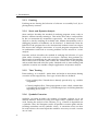
2. Background
researchers, saving them time for the analysis of the actual firmware image.
Unfortunately, even though presented in 2012, there has never been a public
release of a whitepaper or sourcecode of FRAK so far. Similar to what FRAK
is supposedly able to do, our framework allows to reuse existing functionality and to easy inject it into the firmware binaries that are parsed.
Dytan: A Generic Dynamic Taint Analysis Framework
Clause et al. [7] proposed Dytan, a platform to instrument binaries with
taint tracking abilities at runtime in a generic way. Previous contributions
in the area of dynamic taint tracking were lacking usability:
• The tools were defined ad-hoc, i.e. for a certain application only
• Most tools considered data flow tracking only
Dytan offers a solution to easily instrument new binaries with the ability
to track both data and control flows. In contrast to Dytan, our framework
is not limited to performing taint tracking, but offers a much more generic
solution to cleanly integrate any analytical functionality into binaries.
S2E: Selective Symbolic Execution
Chipounov et al. [8] presented S2E or Selective Symbolic Execution, a platform that is used to develop tools that e.g. perform reverse engineering
or bug hunting tasks with the help of symbolic execution. As symbolic
execution analyzes all possible execution paths, the amount of data to be
analyzed explodes with increasing binary size. The key contribution behind
S2E therefore is the introduction of selective symbolic execution, which automatically reduces the code to be executed symbolically to a minimum. With
this approach, analysis of large binaries - the paper states it could be used
to evaluate the whole windows stack - becomes feasible.
6
Chapter 3
The AutoHook Framework
3.1
Overview
AutoHook is a platform for redirecting control flow in a flexible, and userfriendly manner. Flow is redirected to a target of choice, including external
functionality provided as binaries. Our framework will cleanly integrate
the new functionality into the provided firmware binaries, thus enabling
researchers to perform dynamic analysis on the device itself. In the current
version, AutoHook includes support for ARM, MIPS and Thumb2 instruction
sets. Adding new instruction sets can however easily be done (Sections 3.4.3
and 3.5).
Flat binaries
ELF files
AutoHook
Existing
functionality
(binary)
Assembly
stubs
JTAG commands
Config
files
Disassembly
engine
Custom Firmware
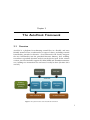
Figure 3.1: System model of the AutoHook framework
7
3. The AutoHook Framework
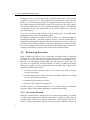
In Figure 3.1, the system model of the AutoHook framework is shown from
a high-level point of view. We designed the framework to work with flat
binaries, as most firmware images are supplied in this form. However, we
also added support for ELF files in order for AutoHook to be able to parse
any desktop application as well. Loading of multiple binaries (or ELF files)
is supported, in case the functionality of the device under test is split up
into several parts.
In its core, the framework consists of three major parts: Assembly stubs,
configuration files and a disassembly engine.
The biggest strength of AutoHook is, that it allows to seamlessly integrate
existing functionality - provided in binary format - into the control flow of
the firmware image that is parsed. This means, that you can take C code that
performs taint tracking, compile it to the same architecture as the device that
you are investigating, and AutoHook will inject the functionality and alter the
existing control flow to redirect calls to the newly added routines.
3.2
Redirecting Execution
From a high-level point of view, redirecting execution looks as depicted
in Figure 3.2. After selecting what function to redirect, a wrapper has to
be injected. The location of the wrapper could be any unused part of the
firmware, e.g. debugging symbols that were left and never used. The next
step then is to patch the selected function, in order to redirect execution
flow to the wrapper once the patched location is reached. The wrapper then
performs the following actions:
1. Save the current execution state (as you want to be able to cleanly
resume afterwards)
2. Call the target (this is where execution should be redirected to, could
be any external functionality)
3. Restore the previously saved state
4. Return to the original execution flow
AutoHook allows to perform redirection of execution using two different
methods: Either using pointer patching or instruction patching.
3.2.1
Instruction Patching
When the current hook is configured to use instruction patching, execution
is redirected by replacing instructions, that allow to jump out of the original
execution flow. However, patching instructions on the binary level is not
trivial, as many instructions depend on their position within the binary. If
8
3.2. Redirecting Execution
Firmware
Patch
Function
Target
Wrapper
Figure 3.2: Redirecting execution from a high-level point of view
these instructions are replaced and executed somewhere else, the results can
be completely different:
• Branches are often PC relative and would need to be recalculated if
replaced and executed in the wrapper. Depending on the range of PC
relative addressing and the location of the wrapper, recalculation may
not even be possible.
• Branches occurring before the inserted hook may lead to cases where
the hook is never reached.
• Some instruction sets use PC relative addressing as well for register
loading, leading to similar problems as with PC relative branching.
As the replaced instructions have to be executed at some point in order
to cleanly resume the original flow, we use a blacklisting approach to prevent overwriting of critical instructions. A simple heuristic scans for bad
operands, bad mnemonics (Section 3.4.2) and checks for proper instruction
alignment in order to determine where it is best to place the hooking code.
If a suitable place is found, code to jump to the wrapper is injected. The actions that the wrapper performs are very similar to the high-level example:
1. Save current execution state
2. Call the target
3. Restore the previously saved state
9
3. The AutoHook Framework
①
Inject wrapper code,
Start looking for replaceable
instructions
② including instructions to be
replaced
Firmware Binary
Firmware Binary
0x000000
0x000000
...
0x2E2054
0x2E2058
0x2E205C
0x2E2060
0x2E2064
TST R0, #3
PUSH {R4, LR}
MOV R4, R0
TSTEQ R1, #3
BNE #0x28
③
Firmware Binary
0x000000
...
0x2E2054
0x2E2058
0x2E205C
0x2E2060
0x2E2064
...
TST R0, #3
PUSH {R4, LR}
MOV R4, R0
TSTEQ R1, #3
BNE #0x28
...
0x2E2054
0x2E2058
0x2E205C
0x2E2060
0x2E2064
...
0x5c7140
PUSH {R0-R12, LR}
BL TARGET
POP {R0-R12, LR}
TST R0, #3
PUSH {R4, LR}
LDR PC, [PC, #-4]
.word 0x2E205C
0x5DAA53
LDR PC, [PC, #-4]
.word 0x5c7140
MOV R4, R0
TSTEQ R1, #3
BNE #0x28
...
0x5c7140
...
0x5DAA53
Patch instructions (hooking),
redirect execution flow!
PUSH {R0-R12, LR}
BL TARGET
POP {R0-R12, LR}
TST R0, #3
PUSH {R4, LR}
LDR PC, [PC, #-4]
.word 0x2E205C
...
0x5DAA53
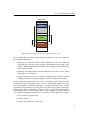
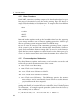
Figure 3.3: Example of instruction patching for ARM assembly. The brown marked instructions
in the firmware binary are the ones being overwritten by the hooking code (blue). The wrapper
code executes the overwritten instructions and resumes the original flow after returning from
TARGET.
4. Execute overwritten instructions
5. Jump back into original context
Figure 3.3 illustrates the different steps involved when AutoHook is configured to use instruction patching.
3.2.2
Pointer Patching
If pointer patching is chosen, it is assumed that the function to be redirected
is called using a function pointer, as for instance, is heavily done in C++
programs. AutoHook will replace that pointer to call a wrapper routine. The
actions that the wrapper routine performs differ only marginally from the
mentioned high-level example:
1. Save current execution state
2. Call the target
3. Restore the previously saved state
4. Call the original function
5. Return
10
3.3. Memory and Binary Modifications
3.3
Memory and Binary Modifications
AutoHook is an execution redirecting framework, and it achieves this functionality by either modifying the contents of a firmware image directly, or
its running copy that resides in memory. The framework generates patches
for all redirections and additional functionality, which can then be integrated
into existing control flow using one of two available types of patching - persistent and non-persistent patching.
Memory Layout
Firmware
Bootloader
Patches
Patches
Operating
System
Code
General RAM
Data
(a)
(b)
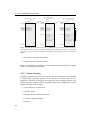
Figure 3.4: Figure (a) shows the memory layout of an embedded device after non-persistent
patching was used, whereas figure (b) shows the altered firmware image after AutoHook was run
in persistent patching mode.
3.3.1
Non-Persistent Patching
Non-persistent patching is the default mode. In this mode, AutoHook assumes that the target has JTAG connectivity available and enabled. As JTAG
allows to peek and poke around in the memory, our framework uses these capabilities to load all generated patches directly into the copy of the firmware
image that resides in memory. Figure 3.4 (a) shows the final memory layout
of an embedded device, after all patches were loaded using JTAG. On a subsequent boot of the device, a fresh, unaltered copy of the firmware binary
will be loaded into memory, hence the name non-persistent patching is used.
As output, the framework will display instructions to be fed to OpenOCD,
a common opensource tool used for JTAG access.
11
3. The AutoHook Framework
3.3.2
Persistent Patching
In this mode, AutoHook will not integrate the patches into a copy of the
firmware image loaded in memory, but actually alter the original firmware
binary itself. As output, the framework will generate a custom firmware
image that integrates all redirections and added functionality. The final
result is depicted in Figure 3.4 (b). This image can then be flashed onto the
device, which means, that on every boot of the device, the already altered
and patched version of the firmware binary will be loaded, resulting in
persistent patching.
3.4
Core Components
The AutoHook framework consists of three major parts: Assembly stubs, configuration files and disassembly engine.
3.4.1
Assembly Stubs
Assembly stubs are files filled with assembly code and interleaved with
placeholders. AutoHook uses these files as templates for code injection, for
instance for the wrapper routine. Assembly stubs need to be present in order for AutoHook to support a specific instruction set. By using a naming
convention for the files, our framework is able to automatically select the
correct stub file to use, based on the current instruction set and patching
method chosen.
Stub files are located within the stubs/ subdirectory. All files should use a
filename consistent with the name of the instruction set and as file extension
the ones described in the next few paragraphs:
File Extension .pp eq
If the hook being parsed uses pointer patching as hooking method, AutoHook
will select this stub file to be used as the wrapper. The first part of the
file extension (pp) tells AutoHook that it is used for pointer patching. The
second part (eq) tells that the target function (where control flow should be
redirected to) is using the same instruction set as the code being redirected.
This distinction enables hooking of functions within firmware binaries that
use more than one instruction set. For instance in the case of ARM and
Thumb2 instruction sets, the code can switch between these two by setting
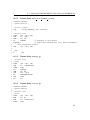
or unsetting the least significant bit of the PC register. Figure 3.5 shows
the stub used for pointer patching in case of the MIPS instruction set. By
patching a function pointer, our stub essentially gets called as a function meaning that we do not need to care about calculating correct return values.
Besides the TARGET - where the flow will be redirected to - the address of the
12
3.4. Core Components
.text
main:
addi
sw
sw
sw
sw
sw
sw
sw
sw
sw
jal
lw
lw
lw
lw
lw
lw
lw
lw
addi
jal
sw
addi
jr
$sp, $sp, -36
$s0, 0($sp)
$s1, 4($sp)
$s2, 8($sp)
$s3, 12($sp)
$s4, 16($sp)
$s5, 20($sp)
$s6, 24($sp)
$s7, 28($sp)
$ra, 32($sp)
TARGET
$s0, 0($sp)
$s1, 4($sp)
$s2, 8($sp)
$s3, 12($sp)
$s4, 16($sp)
$s5, 20($sp)
$s6, 24($sp)
$s7, 28($sp)
$sp, $sp, 32
REPLACED_STUFF
$ra, 0($sp)
$sp, $sp, 4
$ra
Figure 3.5: MIPS32.pp eq stub. All registers that are either used as function arguments or
defined to be saved by the callee are pushed to the stack before calling the target.
function that would have been called originally, needs to be inserted as well
(placeholder REPLACED STUFF).
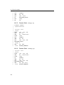
File Extension .hook
The idea of the .hook files is to contain the absolute minimum amount of assembly code that is necessary to jump to an arbitrary location within a 32bit
address space. Additionally, no other registers than the PC register should
be involved, in order to be able to resume the execution in the exact same
state after redirecting. These are the instructions that redirect control flow
to the wrapper when a hook is configured to use instruction patching. Figure 3.6 shows that in the case of the ARM instruction set two instructions are
13
3. The AutoHook Framework
.section .text
_start:
LDR
PC, [PC, #-4]
.word
WRAP_ADDRESS
Figure 3.6: ARM.hook stub. Only two instructions are necessary to jump to an arbitrary 32bit
address. No registers beside the PC register are affected.
# Enable Thumb2
.syntax unified
.section .text
_start:
PUSH
{R0 - R12, LR}
BL
TARGET
POP
{R0 - R12, LR}
REPLACED_STUFF
.align 2
LDR
PC, [PC]
.word
RETURN_ADDRESS
Figure 3.7: Thumb2.ip eq stub.
sufficient to achieve this goal. The placeholder variables WRAP ADDRESS will
be replaced by the location where the wrapper code is stored (configuration
option wrap loc, Section 3.4.2).
File Extension .ip eq
If the hook being parsed uses instruction patching as hooking method, this
stub file will be used for the wrapper. The first part of the file extension
(ip) tells AutoHook that it is used for instruction patching. The second part
(eq) then tells AutoHook - as mentioned above - that the target function is
using the same instruction set as the code being redirected. In contrast to
pointer patching, where return values are taken care of automatically, these
need to be determined by AutoHook while patching. Additionally, as we use
instruction patching for redirecting the flow of execution, the overwritten
instructions need to be executed before jumping back. Figure 3.7 shows the
stub used for instruction patching in in case of the Thumb2 instruction set.
The TARGET placeholder has the same function as mentioned above in the
14
3.4. Core Components
.pp eq files. The REPLACED STUFF placeholder however is not replaced by a
function address, but by the instructions overwritten by the hooking code.
As the instruction patching method jumps out of the original execution flow
in the middle of a function, a suitable RETURN ADDRESS needs to be calculated
to be able to resume execution after redirection.
File Extensions .pp ne and .ip ne
The files with extensions .pp eq, .hook and .ip eq are mandatory and AutoHook relies on them to support a certain instruction set. The files with
extensions .pp ne and .ip ne however are optional. As mentioned above,
there are cases where the instruction set of the code being redirected differs from where the flow should be redirected to. If this is the case, these
optional files need to be provided.
Custom Stubs
The subdirectory custom stubs/ can be used whenever there is need for
functionality that differs from the default stubs available. AutoHook will not
automatically search for custom stubs, thus no special naming convention is
needed. Instead, the configuration option custom stub (Section 3.4.2) has to
be specified, such that this stub will be used. One example of custom stubs
might be for instance what we call halting hooks. These hooks redirect parts
of code that is only reached whenever a special event happens that is of some
sort of interest. The name halting hook suggests that instead of resuming the
original flow after redirecting the hook will end up in an endless loop.
Custom hooks can (but do not need to) incorporate all placeholders available
in the default stubs. In addition - to make the use of custom stubs more
versatile - custom placeholders named CUSTOM 1 to CUSTOM 9 can be used.
The values to replace with are specified within the hook configuration file
(Section 3.4.2).
Figure 3.8 shows an example of a halting hook written in Thumb2 assembly.
Out of the available default placeholders, only TARGET is used. In this case
we intended to print a message to STDOUT to notify the researcher that something important happened. In order not to write a different stub for each
place to hook, we made use of the custom placeholders; CUSTOM 1 takes care
of an individual output message, and CUSTOM 2 is used for additional instructions, e.g. calling another subroutine. If no additional instructions are
necessary, CUSTOM 2 would be left empty in the configuration file.
3.4.2
Configuration Files
Configuration files are located within the subdirectory cfg/. There is a main
configuration file, called instruction sets.cfg, that has to be available in
15
3. The AutoHook Framework
# Enable Thumb2
.syntax unified
.section .rodata
msg:
.string "CUSTOM_1 LR: 0x%08x\n"
.section .text
PUSH
{R0 - R12, LR}
LDR
R0, =msg
MOV
R1, LR
BL
TARGET
CUSTOM_2
POP
{R0 - R12, LR}
_end:
B
// designed to call printf
// additional instructions
_end
Figure 3.8: Example stub for a halting hook in Thumb2 assembly
order for AutoHook to run.
Main Configuration File: instruction sets.cfg
The sections within this configuration file contain - besides the default stubs
- the necessary information for AutoHook to support a new instruction set.
In Figure 3.9 we show the section of instruction sets.cfg that integrates
ARM support in AutoHook. The name of the section can be chosen arbitrarily
but has to match the filename of stub files. The first five settings specify shell
commands that are used to compile the stubs. As we want to support both
little and big endian encoded binaries, there are two settings for compiler
and linker each. AutoHook produces flat binary patches - therefore a call to
objcopy is necessary to convert the .elf file created by the linker to a flat
binary. The two placeholders ADDRESS and OUTFILE need to be present for
AutoHook to work properly. ADDRESS is used to tell the linker where the binary will be located in memory - this results in smaller size of the generated
binaries when calls to functions are within the reach of PC relative offset. As
AutoHook relies on Capstone to produce disassembly, the correct architecture
and mode needs to be specified using capstone arch and capstone mode.
While trying to find a suitable place to hook, AutoHook uses the space separated lists in bad operands and bad mnemonics to skip (and not replace)
potentially critical instructions. In the example of the ARM instruction set
we chose pc as bad operand such that instructions using pc-relative address16
3.4. Core Components
[ARM]
compiler_little = arm-none-eabi-as -o /tmp/hook_tmp.o
/tmp/hook_tmp.in
compiler_big
= arm-none-eabi-as -o /tmp/hook_tmp.o
/tmp/hook_tmp.in
linker_little
= arm-none-eabi-ld -EL -Ttext=ADDRESS
/tmp/hook_tmp.elf /tmp/hook_tmp.o 2> /dev/null
linker_big
= arm-none-eabi-ld -EB -Ttext=ADDRESS
/tmp/hook_tmp.elf /tmp/hook_tmp.o 2> /dev/null
objcopy
= arm-none-eabi-objcopy -O binary
/tmp/hook_tmp.elf OUTFILE
capstone_arch
= CS_ARCH_ARM
capstone_mode
= CS_MODE_ARM
bad_operands
= pc
bad_mnemonics
= b cb
addr_add
= 0
align
= 4
-EL
-EB
-o
-o
Figure 3.9: Section adding ARM support in instruction sets.cfg
ing will not be replaced by our hook. All bad mnemonics mark only the
beginning of disassembled mnemonics, meaning that instructions such as
blx and cbz would be caught as well by our blacklist.
The addr add option allows to specify flags that will be added to a calculated
address. This involves return addresses and addresses to jump to. This way
switching between Thumb2 and ARM instruction set gets possible. In the
case of Thumb2 the option addr add is set to 1.
The last option, align, specifies the byte alignment for instructions, namely
for the hook to be inserted when using instruction patching.
Device / Firmware specific Configuration Files
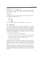
For each device / firmware configuration that needs to be patched, a researcher should create a new configuration file. Figure 3.10 shows an example of a device and firmware specific configuration file. The first section
[DEFAULT] is mandatory. The only mandatory setting in the default section
is endian where endianness is specified as a Capstone constant. Additionally, two optional settings are available:
pre cmds: OpenOCD commands that will be prepended to the automatically generated command list. Can be useful to clear parts of memory
or for manual patching (e.g. we used this to redirect STDOUT to the
UART connection in one of our case studies).
17
3. The AutoHook Framework
[DEFAULT]
endian
= CS_MODE_LITTLE_ENDIAN
[undefined_instruction]
patch_method
= pointer
source_loc
= 0x40000040
source_instr_set
= Thumb2
wrap_loc
= 0x405C7000
target
= 0x401BA018
target_instr_set
= Thumb2
custom_stub
= halt_hook_thumb2_eq.wrap
CUSTOM_1
= Undefined Instruction!
CUSTOM_2
= BLX 0x405C7300
[background_task]
patch_method
source_loc
source_instr_set
wrap_loc
target
target_instr_set
target_binary
=
=
=
=
=
=
=
instruction
0x40015C70
Thumb2
0x405C7140
0x405C7300
ARM
compress.bin
Figure 3.10: Example of device / firmware specific configuration file
post cmds: Same as pre cmds but supplied commands will be appended to
the generated list.
When run in persistent patching mode, AutoHook is able to use some of these
additional OpenOCD commands as well. The mwb, mwh, mww and load image
(flat binaries only) commands are supported and the changes are written
directly into the produced custom firmware.
All other sections are optional, one for each hook to be placed. The name of
a hook section can be chosen arbitrarily, but it will be used for newly created
binaries and various output by AutoHook messages and should therefore be
chosen carefully.
A hook section contains several mandatory settings:
patch method: Can either be set to instruction (if existing code should
be patched to redirect execution flow), or to pointer if patching of a
function pointer is required.
source loc: Specifies the location in memory where AutoHook should start
18
3.4. Core Components
looking for instructions to replace (instruction patching) or where the
function pointer is located (pointer patching).
source instr set: Specifies what type of instruction set is used in the code
being redirected. Determines what kind of instruction set the stubs
will be compiled to as well.
wrap loc: Position in memory where the newly created wrapper should be
loaded to (or written to when persistent patching is enabled)
target: Address that will replace the TARGET placeholder in the stubs (Figures 3.5, 3.7 and 3.8 for examples).
target instr set: Most of the time this will be set to the same value as
source instr set, can however differ if one wants to e.g. switch from
ARM to Thumb2 instruction set.
In addition to these mandatory settings, several optional ones exist as well:
target binary: If TARGET points to code that is not part of the original
firmware binary, the binary containing the code can be specified. AutoHook will generate an additional load instruction for this binary if it
is run in non-persistent patching mode. In persistent patching mode,
the external binary will be injected into the custom firmware as all
other patches. Target binaries are assumed to be flat, ELF loading is
not supported.
custom stub: If specified, AutoHook will not automatically determine what
stub to use (based on patching method and instruction sets) but instead use the specified file. Custom stubs need to be located in the
custom stubs/ subdirectory.
CUSTOM 1 - CUSTOM 9: These settings allow arbitrary replacements in custom
stubs.
force patch: Boolean value, optional. If set to true, AutoHook will patch
hooking instructions at the next aligned address starting from source loc,
ignoring conflicts issued by either bad operands or bad mnemonics.
This is useful if no suitable location can be found and either a custom stub will take care of the problem or one does not expect the hook
to return at all (e.g. halting hooks).
3.4.3
Disassembly Engine
Whenever instruction patching is used, AutoHook has to disassemble the
points of interest in order to find a suitable place to hook. We rely on
the Capstone disassembly framework to provide decoded instructions. Capstone is implemented in pure C and provides bindings for several different
19
3. The AutoHook Framework
programming languages, including Python. Many different architectures
and modes are supported:
• ARM
• ARM-64
• Intel
• MIPS
• PowerPC
• Sparc
• SystemZ
• XCore
For a complete list of supported modes and architectures see the framework’s website [13].
3.4.4
Firmware Binaries
Besides a suitable disassembler, AutoHook also needs access to the original
firmware binaries. Multiple firmware binaries can be supplied - in case the
functionality of the device under test is split up into several parts. Two type
of binaries are supported: Flat binaries, and ELF files. If flat binaries are
supplied, both the filename and the loading address have to be provided
in pairs. In case that ELF files are supplied, the filename is sufficient as
the loading address can be determined automatically. However, there are
certain restrictions when working with ELF files:
• PIE (relocatable .text segment) is not supported
• Stripped ELF files are not supported
• Analysis and patching is only available for the .text segment
3.4.5
Adding new Instruction Sets
AutoHook can easily be extended to support any instruction set as long as it is
supported by Capstone. The following paragraphs show the steps necessary
in order to successfully add support for a new instruction set.
GCC Toolchain and Binutils
All stubs need to be compiled and converted to flat binaries before either
loading them in OpenOCD or integrating them into the original firmware.
For compilation and linking the GCC toolchain for the new instruction set
needs to be available. The binutils (for this specific instruction set as well)
need to be present to convert the compiled ELF file in to a flat binary.
20
3.5. Discussion
New Section in instruction sets.cfg
Similar to Figure 3.9 a new section needs to be added to the main configuration file instruction sets.cfg. See Section 3.4.2 for details on the configuration settings.
Create Stubs
Assuming new section was named NAME, at least the following files need to
be created in the subdirectory stubs/:
• NAME.hook
• NAME.ip eq
• NAME.pp eq
See Section 3.4.1 for details on what placeholders need to be present.
3.5
Discussion
The AutoHook framework allows to redirect control flow in a very flexible
manner to a target of choice using simple configuration files. What this
means is, that AutoHook allows a researcher to save time, as creating a configuration file is all that needs to be done in order to instrument a firmware
binary with new functionality. Assume a researcher does not have AutoHook.
In order to achieve redirection of execution flow manually, the following
steps would need to be performed:
1. Search for a suitable place to start redirecting.
2. Generate and inject assembly code that performs the actual redirection.
3. Edit patches to reflect the replaced instructions and all references to
the location in memory where the wrapper will reside.
4. Compile and inject the patches.
Additionally, whenever a new firmware revision is released, one has to start
with this process all over again. Using AutoHook however, this process is
reduced to just one step - creating a configuration file. In order to support
new firmware revisions, all that has to be done is to adjust that configuration
file.
AutoHook is designed to be very flexible. It leaves the researcher with complete freedom of choice on what kind of functionality should be added. Furthermore, adding support for new instructions sets is a one time procedure,
which only consists of altering a configuration file and creating three assembly stubs.
21
3. The AutoHook Framework
[DEFAULT]
endian
= CS_MODE_LITTLE_ENDIAN
[strcpy]
source_loc
source_instr_set
patch_method
wrap_loc
target
target_instr_set
target_binary
=
=
=
=
=
=
=
0x40015C70
Thumb2
instruction
0x405C7140
0x405C7300
ARM
function.bin
Figure 3.11: test.cfg configuration file, containing only one hook, that redirects strcpy() to
functionality loaded from function.bin
Firmware
Patch
Function
strcpy()
Target
function.bin
Wrapper
Figure 3.12: Abstracted view of a redirection from strcpy() to custom functionality loaded
from function.bin
3.6
Example Usage
If a researcher wants to redirect calls to strcpy() to its taint tracking routine
residing in function.bin, all she needs to do is to create the configuration file
shown in Figure 3.11.
Figure 3.12 shows the resulting, abstracted version, of the new execution
flow that AutoHook generated using the test configuration file. This is achieved
22
3.6. Example Usage
...
[strcpy] Start parsing
[strcpy] Going for instruction patching.
[strcpy] Writing binary to bin/strcpy_hook.bin
[strcpy] Will replace the following instructions (*):
[strcpy] *
0x40015c70:
movs
r3, #1
[strcpy] *
0x40015c72:
add
r2, sp, #4
[strcpy] *
0x40015c74:
mov
r0, r3
[strcpy] *
0x40015c76:
add
r1, sp, #8
[strcpy]
0x40015c78:
bl
#0xbf010
[strcpy]
0x40015c7c:
cmp
r0, #0
[strcpy] Writing binary to bin/strcpy_wrap.bin
[strcpy] Wrapper binary is 28 bytes. Make sure the
specified wrap_loc provides enough space.
All done! Please copy all binary files from the bin
directory (and - if specified - target binaries as
well) to your OpenOCD working dir! Then paste the
following commands into your OpenOCD shell:
load_image strcpy_hook.bin 0x40015c70 bin
load_image strcpy_wrap.bin 0x405c7140 bin
load_image function.bin 0x405c7300 bin
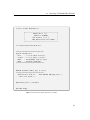
Figure 3.13: AutoHook: Partial output in non-persistent patching mode using the test.cfg
configuration file
by starting AutoHook with the following command:
$ ./AutoHook.py cfg/test.cfg B3740BUKA2.mac 0x40000000
The first argument is the device / firmware configuration. Following this,
arguments need to be supplied either in pairs consisting of the name of the
firmware binary and the address where the binary would be mapped to
in memory (flat binaries) or the filenames only if ELF files are used. Figure 3.13 shows parts of the output produced by AutoHook when started
with the command mentioned above. It starts parsing the provided configuration file (test.cfg) for hooks that should be applied. In this example
the only hook present is configured to use instruction patching. If a hook
uses instruction patching, AutoHook will display the instructions that were
replaced during the patch process (marked with at star). After all hooks are
parsed and patches are generated, AutoHook shows the commands to be fed
to OpenOCD.
23
3. The AutoHook Framework
...
[strcpy] Start parsing
[strcpy] Going for instruction patching.
[strcpy] Writing binary to bin/strcpy_hook.bin
[strcpy] Will replace the following instructions (*):
[strcpy] *
0x40015c70:
movs
r3, #1
[strcpy] *
0x40015c72:
add
r2, sp, #4
[strcpy] *
0x40015c74:
mov
r0, r3
[strcpy] *
0x40015c76:
add
r1, sp, #8
[strcpy]
0x40015c78:
bl
#0xbf010
[strcpy]
0x40015c7c:
cmp
r0, #0
[strcpy] Writing binary to bin/strcpy_wrap.bin
[strcpy] Wrapper binary is 28 bytes. Make sure the
specified wrap_loc provides enough space.
Start patching firmware binaries...
[B3740BUKA2.mac] Offset 0x00015c70: Incorporating binary
bin/strcpy_hook.bin
[B3740BUKA2.mac] Offset 0x005c7140: Incorporating binary
bin/strcpy_wrap.bin
[B3740BUKA2.mac] Offset 0x005c7300: Incorporating binary
bin/function.bin
[B3740BUKA2.mac] Patched firmware file written to
bin/patched_B3740BUKA2.mac
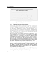
Figure 3.14: AutoHook: Partial output in persistent patching mode using the test.cfg configuration file
By specifying -p DIR in front of the configuration file parameter AutoHook
switches to persistent patching mode:
$ ./AutoHook.py -p bin cfg/test.cfg B3740BUKA2.mac 0x40000000
Figure 3.14 shows parts of the generated output when the framework is run
in persistent patching mode. Instead of OpenOCD commands at the bottom,
AutoHook shows the offsets within the firmware binaries that were patched.
24
3.7. Obtaining AutoHook
3.7
Obtaining AutoHook
This PDF document contains a ZIP archive within itself:
$ unzip AutoHook.pdf
Thanks to Ange Albertini for the instructions on how to cleanly integrate a
ZIP file [14].
Unfortunately, due to automatic processing of PDF files in the ETHZ digital
library, the ZIP file in the present document is corrupted. Please see the mirror http://hisr.ch/AutoHook.pdf for the original version of this document
or use the ZIP file attached to the E-Collection record.
25
Chapter 4
Applications
We show that our framework helps in reverse engineering and performing
security analysis of a real-world embedded device. We additionally show
that the concept of AutoHook works equally well on a desktop application
for a different architecture.
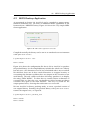
4.1
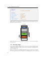
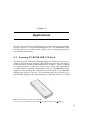
Samsung GT-B3740 USB LTE Stick
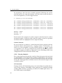
The Samsung LTE USB Stick GT-B3740 (Figure 4.1) enables PC users to establish a data connection using the LTE cellular Network (4G). The stick is
manufactured by Samsung and distributed by Vodafone. As the GT-B3740
is a LTE only device, it cannot be used in areas where only GSM/EDGE
or UMTS/HSPA is available. Furthermore, only the LTE 800 MHz band is
supported, thus limiting the connectivity in Switzerland as the 800 MHz
Support just started to roll out. The baseband processor in the device is
the CMC220, designed and manufactured by Samsung, based on a ARM
Figure 4.1: Samsung LTE USB stick GT-B3740
Source: http://www.teamsix.it/cms/product images/45/38/09/LTE-Surf 241088.jpg
27
4. Applications
reset_config trst_and_srst
if { [info exists CHIPNAME] } {
set _CHIPNAME $CHIPNAME
} else {
set _CHIPNAME cmc220
}
if { [info exists ENDIAN] } {
set _ENDIAN $ENDIAN
} else {
set _ENDIAN little
}
if { [info exists DAP_TAPID ] } {
set _DAP_TAPID $DAP_TAPID
} else {
set _DAP_TAPID 0x4ba00477
}
jtag newtap $_CHIPNAME dap -irlen 4 -ircapture 0x1 -irmask
0xf -expected-id $_DAP_TAPID
set _TARGETNAME $_CHIPNAME.cpu
target create $_TARGETNAME cortex_r4 -chain-position
$_CHIPNAME.dap -dbgbase 0x8000c000
Figure 4.2: OpenOCD configuration file for Samsung LTE USB stick GT-B3740
Cortex-R4 processor.
4.1.1
Debug Access
A blog post from P1 Security [15] showed that debug access to the device is
easily achieved: The JTAG connector was labeled with JTAG, due to a leaked
service manual the pinout was known and an appropriate JTAG connector
is available for purchase online. In order to get the JTAG access working
we had to tweak the original OpenOCD configuration presented in the blog
post (Figure 4.2).
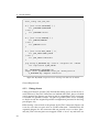
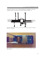
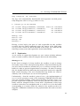
When having a closer look at the pinout of the JTAG connector (Figure 4.3)
it can be seen that two pins refer to UART connection. Unfortunately the
acquired adapter for the connector did not provide access to these pins only the JTAG relevant pins were mapped. With - a lot of - try and error we
28
4.1. Samsung GT-B3740 USB LTE Stick
managed to solder two wires without breaking the possibility to attach the
acquired cable to the connector. The result is shown in Figure 4.4.
VDD_1.8V VBUS_5.0V
VDD_1.8V
R400
HDC401
2
4
6
8
10
12
2
4
6
8
CMC_TDO
RESET_IN
10
12
UART0_TX
D404
R402
1
1005
9
11
1
3
5
7
9
11
LXES15AAA1-075
7
3
5
13 NC
14 NC
15 NC
16 NC
CMC_TRSTN
CMC_TDI
CMC_TMS
CMC_TCK
UART0_RX
Figure 4.3: Schematics of the JTAG connector used on the Samsung LTE USB stick GT-B3740
Source: P1 Security [15]
Figure 4.4: Soldered wires to UART pins on the JTAG connector of the Samsung LTE USB
stick GT-B3740
29
4. Applications
4.1.2
Boot Procedure
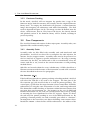
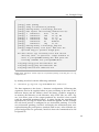
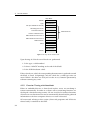
With UART connection working, output of the bootloader helped to get a
first grasp of what kind of system the stick is running. Figure 4.5 shows the
output of the bootloader on stock firmware. The output shows four different
entries in the system information listing:
• Boot
• Loader
• MAC1
• MAC2
Boot and loader together make up the bootloader that loads the operating
system image and takes care of firmware updating procedures. MAC1 specifies the operating system image and MAC2 a fallback image.
In order to start the analysis of the embedded operating system, copies of
all the system’s parts needed to be obtained. We downloaded a firmware
update and extracted the firmware image (MAC1) out of it. As the firmware
update did not contain updates for either the boot or the loader part of the
system, we had to extract their copies from the running device using JTAG.
4.1.3
Firmware Update Mechanism
The official firmware update tool features several switches that can be used
to flash all previously mentioned parts of the system.
-b *.but: Flash a new Boot image.
-l *.ldr: Flash a new Loader image.
-m1 *.mac: Flash a new OS image to MAC1.
-m2 *.mac: Flash a new OS image to MAC2.
-i *.iso: Flash a new ISO-image. The ISO-image provides the management software and is automatically loaded when no specific driver is
(yet) installed on the host computer.
The firmware images are neither signed nor encrypted, thus allowing downgrading and flashing of custom firmwares without the need of further patches
or exploitation. An example upgrade procedure (taken from the latest update available) looks as follows:
C:\> GT-B3740 FWUp.exe -m1 B3740 LTE.mac -i CdRom.iso
30
4.1. Samsung GT-B3740 USB LTE Stick
<< Boot Loader Running!!>>
+-------------------------------------+
|
CMC220 Boot 1G
|
|
BOOT for LOADER1
|
|
S/W Version 1.0.5.0
|
|
DVS_SEL,Version info,UART0 |
+-------------------------------------+
<< Loader1 Code Down Done!!>>
================================
System Information
Boot
: 1.00.05 (Mar 24 2010)
Loader : 1.00.07 (May 6 2010)
MAC1
: B3740BUKA2 (Jan 27 2011)
MAC2
: Unknown (Unknown)
================================
CMC2XX Firmware XSR [ May 6 2010 ]
================================
Current Boot mode is :
Run CMC2XX MAC App mode !!
... Auto boot Start !!
MAC Binary size = 0x5c6a54
Run MAC Image
Figure 4.5: Bootloader output observed over UART
31
4. Applications
===================================================
CMC220 DEVELOPMENT PLATFORM
- ARM Emulation Baseboard | Cortex-R4
- Software Build Date : 27/01/2011_15:05:10
- Software Builder
: yd.lim
- Compiler Version
: ARM RVCT 3.1 [Build 700]
Platform Abstraction Layer (PAL) Powered by
Modem H/W Lab BSP SW Part
===================================================
Figure 4.6: Debugging output after redirecting STDOUT
4.1.4
Embedded Operating System Analysis
Analysis of the firmware binary revealed that the operating system is a proprietary, multitasking system. The operating system does not implement
pre-emptive scheduling, meaning that tasks run to completion before execution is passed on. Additionally, the system is a monolithic operating system,
which means that there is no separation between tasks - all of them share
the same memory space. As all tasks run in the highest available processing
mode - the Supervisor mode - a bug in any task can lead to the compromisation of the whole operating system.
Reverse engineering of the bootloader showed that the MAC image chosen
to run is loaded to 0x40000000 in memory. A total of 16 megabytes of RAM
(addresses 0x40000000 - 0x40FFFFFF) is reserved for the OS (MAC) image
to be loaded to. The memory starting at 0x41000000 up to 0x43FFFFFF is
reserved for stack and heap usage. After the bootloader passes execution to
the OS image, the stack and heap get initialized and the mainTask is started.
The mainTask then takes care of further startup procedures, namely reading
and parsing configuration files and starting all other necessary tasks.
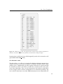
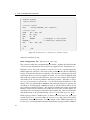
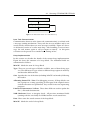
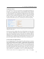
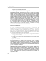
With the correct load address, IDA Pro is quickly able to find many references to strings, thus revealing the printf() function immediately. As the
firmware is neither signed nor encrypted, we wrote a quick patch to redirect STDOUT to our UART connection. This provided plenty of additional
debugging information. Figure 4.6 shows some of the new debugging output revealing the used compiler version.
In this case, ARM RVCT 3.1 [Build 700] was used. As IDA Pro has signatures for exactly this version of the libraries used, we could quickly identify
interesting functionality that helped with further analysis.
32
4.1. Samsung GT-B3740 USB LTE Stick
Task main entry
pal_MsgReceiveMbx()
Task related actions
Figure 4.7: Abstracted version of a tasks main loop
Inter Task Communication
Communication between tasks (inter task communication) is realized with
a message sending mechanism. Every task has its own mailbox and it constantly checks whether there are new messages available. Figure 4.7 shows
an abstracted version of a tasks main loop. After handling a received message, the task returns again to call pal MsgReceiveMbx(). At this point
execution can be passed on to another task waiting in line.
Heap Implementation
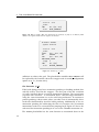
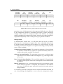
In this section we describe the details of the custom heap implementation.
Figure 4.8 shows the structure of a heap block. The individual fields are
summarized as follows:
MAGIC: Marks the start of a heap block.
Type: There are several types of blocks available, most of them being type
0x4. The difference in type relate to different heap regions in memory
and therefore different lists.
Size: Specifies the size of the data (including MAGIC end marker) following
the header.
Allocating Source File / Line: For debugging reasons, all heap blocks contain a pointer to a string specifying in what part of the original sourcecode the allocation was performed. Very useful for reverse engineering
purposes.
Pointer to Datastructure / Offsets: These three fields are used to update the
free / allocated datastructure.
XOR Checksum Serves as integrity check. All previous mentioned fields
(starting with the size field) are XORed and the result stored here.
Data: Here starts the actual content of the heap block.
MAGIC: Marks the end of a heap block.
33
4. Applications
Heap Block
MAGIC
D’OH
Type
0x00000004
Size (incl. MAGIC at the End)
0x00000010
Allocating Source File
Line within that File
XOR Checksum
Pointer to Datastructure
Offset within this Structure 1
Offset within this Structure 2
D’OH
XOR Checksum
DATA
0x41414141
...
0x41414141
...
0x41414141
MAGIC
D’OH
Figure 4.8: Heap block datastructure
Upon freeing of a block several checks are performed:
1. Is the type a valid number?
2. Is there a MAGIC marking at the end of the block?
3. Is the XOR checksum valid?
If these checks are valid, the corresponding datastructure is updated to mark
the block as freed. Surprisingly, only the check for a valid type raises an
error if failed - the other two tests just exit the free() function prematurely
without returning any error.
4.1.5
Function Tracing with AutoHook
When an embedded device is fuzzed and crashes occur, no coredump is
written automatically. In order to evaluate calls to interesting functions we
developed a function tracing routine. We use AutoHook to redirect functions
of interest to our function tracer and to automatically download the gathered
information to the host computer whenever a crash is detected.
All sourcecode relating to this section (client side programs and all device
related code) is attached to this PDF.
34
4.1. Samsung GT-B3740 USB LTE Stick
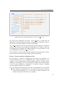
Compression Routine
The compression routine is the main driver of the logging functionality on
the device. As we want the routine to run periodically (interval depends
on how fast the logging buffer tends to fill up), the place to hook needs to
be called frequently as well. Hooking the background task of the operating
system proved to be a good solution for this. Figure 4.9 shows the hook that
redirects execution within the background task to the compression routine.
If more frequent runs of the compression routine would be needed, one
could just add another hook to use a task that gets used more frequently.
[background_task]
patch_method
source_loc
source_instr_set
wrap_loc
target
target_instr_set
target_binary
=
=
=
=
=
=
=
instruction
0x40015C70
Thumb2
0x405C7140
0x405C7300
ARM
compress.bin
Figure 4.9: Background task hook. AutoHook is instructed to generate load commands for the
compression routine as well.
On the first run, the routine takes care of allocating the necessary space
for a temporary logging buffer and enables logging. On every subsequent
start, the routine checks if the size of the logs in the temporary buffer is
bigger than a configurable threshold. If this is the case, the data within the
temporary buffer is compressed using QuickLZ [16] and then copied to the
final buffer. In our implementation, the final buffer is located in a unused
part in the RAM in order to minimize the effect to the system under test.
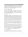
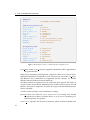
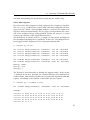
Function Hooks and Logging Routine
In our implementation we were interested in calls to memcpy(), strcat(),
strcpy() and strncpy(), as being able to control input to these functions
often results in buffer overflows. Before a captured call is forwarded to the
logging routine, we have to set up the arguments: These include the value
of the return address (the link register) to see where the call originated from,
the original function arguments, the content to be copied and a marker that
later helps determining what redirected function was called. Due to these
special requirements we could not use generic wrapper stubs but had to
write custom ones. See Appendices A.1.3 to A.1.6 for the detailed listings.
All four custom stubs use the logging procedure as target. The logging
35
4. Applications
Link Register
(0x401b8839)
Type
(memcpy)
Destination
(0x4263cc90)
Source
(0x42db7b20)
Size
(0x100)
39 88 1b 40 6d 65 6d 63 90 cc 63 42 20 7b db 42 00 01 00 00
...
...
...
Data
...
...
...
...
Destination
(0x426e4250)
Source
(0x4265dba0)
Size
(0x27)
...
Data
...
Link Register
(0x402b7849)
Type
(strncpy)
49 78 2b 40 73 74 72 6e 50 42 6e 42 a0 db 65 42 27 00 00 00
...
...
...
...
...
...
...
Figure 4.10: Example log entries within the temporary buffer
procedure saves all information in the temporary buffer that was allocated
by the compression routine as mentioned previously. Figure 4.10 shows
example entries within the temporary buffer. If the buffer is not emptied
quickly enough by the compression routine, and tries to overflow, logging is
suspended temporarily and a warning message is printed to STDOUT.
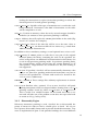
Halting Hooks
As mentioned in Section 3.4.1, we call hooks that end up in an endless
loop instead of resuming the original flow after redirecting halting hooks.
To aid the analysis and notify the researcher if a crash occurred, we used
the halting hook shown in Figure 3.8 to capture interesting (security related)
events. These included:
Undefined Instruction Handler: This would be triggered if a bug allowed
to somehow control the PC register, or if parts of memory where executable code resides would be overwritten.
Software Interrupt Handler: The operating system issues a software interrupt whenever an unrecoverable error happens (e.g. failed type check
in free()).
Data / Prefetch Abort Handlers: This would be triggered if a bug allowed
to control some register values that would point to an invalid location
in memory.
MAGIC Check in free(): As mentioned previously, the operating system
checks if the heap footer is corrupted, but continues to run without
any errors. We hook the part where this check fails in order to detect
heap overflows.
As our halting hook stub is designed to have custom instructions inserted, we
can - after printing what happened - issue a call to the compression routine
36
4.1. Samsung GT-B3740 USB LTE Stick
and start downloading the log file before going into the endless loop.
Client Side Programs
We wrote client side programs to help analyzing the compressed log files.
The receiver.py script listens on the UART connection and prints out messages received. When a downloading marker is received, the compressed
log file is retrieved automatically. The decompress tool performs the extraction of the compressed logs using QuickLZ. Finally, the analyze.py script
analyzes the contents of the logged function traces.
The default way to call the analyze.py script is to not specify anything but
the decompressed dump file as parameter. In this case everything that has
been logged will be displayed as a list of pseudo function calls:
$ ./analyze.py out.bin
ID:
ID:
ID:
ID:
...
ID:
ID:
00000001
00000002
00000003
00000004
memcpy(0x4263cc90,
memcpy(0x4263cc90,
memcpy(0x4263cc90,
memcpy(0x4263cc90,
0x42db7b77,
0x42db7b77,
0x42db7b77,
0x42db7b77,
0x1)
0x1)
0x1)
0x1)
LR:
LR:
LR:
LR:
0x401b8839
0x401b8839
0x401b8839
0x401b8839
00056344 memcpy(0x425f7b68, 0x41da6510, 0xa) LR: 0x40283579
00056345 memcpy(0x425e7c4c, 0x4159f334, 0x18) LR: 0x40010b25
#memcpy: 54968
#strcpy: 1376
#strncpy: 1
The ID field is used internally to identify the logged entries. If the switch
-x followed by an ID is detected, the selected function call is displayed in
verbose mode. This includes, besides the reconstructed arguments and link
register, a hexdump of the contents of the buffer that was copied:
$ ./analyze.py -x 00044585 out.bin
ID: 00044585 memcpy(0x426e9fa0, 0x426e86a8, 0x41) LR: 0x4023d60b
Hexdump:
00000000:
00000010:
00000020:
00000030:
00000040:
37
41
41
41
41
d4
41
41
41
00
11
41
41
41
00
4a
41
41
41
00
a0
41
41
41
00
41
41
41
07
41
41
41
5d
41
41
41
02
41
41
41
00
41
41
41
04
41
41
41
e0
41
41
41
60
41
41
41
c0
41
41
41
40
41
41
41
c1
41
41
41
37
4. Applications
By specifying a four char (hex encoded) argument following the uncompressed log file, the script only displays calls that either match the filter in
one of the arguments, or in the logged content:
$ ./analyze.py out.bin 41414141
ID:
ID:
ID:
ID:
...
ID:
ID:
00044585
00044587
00044589
00044602
memcpy(0x426e9fa0,
memcpy(0x426e9b20,
memcpy(0x42353eb4,
memcpy(0x42353eb4,
0x426e86a8,
0x426e9fa0,
0x4235492f,
0x4235492f,
0x41) LR: 0x4023d60b
0x41) LR: 0x4010ef33
0x3f0) LR: 0x40186f43
0x3f0) LR: 0x40186f43
00056325 memcpy(0x42353eb4, 0x4235492f, 0x3f0) LR: 0x40186f43
00056332 memcpy(0x42353eb4, 0x4235492f, 0x3f0) LR: 0x40186f43
#memcpy: 54968
#strcpy: 1376
#strncpy: 1
The ID used in the example of a verbose output is therefore listed as well in
the filtered output. If both the filter and the examine switch are specified,
the filtered chars are highlighted in the output hexdump.
Custom Firmware
We used AutoHook to produce a custom firmware binary, patched with the
mentioned hooks and compression / logging routines. Furthermore, we
made use of the possibility to specify manual patches (post cmds setting,
see Appendix A.1.1, line 5) to integrate the previously mentioned patches
that redirect STDOUT to UART. See Appendix A.1 for a full listing of the used
configuration file and all involved custom stubs.
4.1.6
Security Analysis
The custom firmware generated by AutoHook allowed capture and trace back
of vulnerabilities. If a stack or heap overflow would happen, one of the introduced halting hooks would be executed, notifying the event and retrieving
the log file. The logged data could then used to trace back the origins of the
occurred overflow.
AT Commands
Playing with the AT Commands parser, our custom firmware quickly discovered a heap overflow vulnerability. When using the AT command AT+CMGS
(sending SMS) and then specifying an SMS text of 400 capital letters “A”,
the UART output would display:
38
4.1. Samsung GT-B3740 USB LTE Stick
Heap corruption!
LR: 0x400a1511
The logs were automatically downloaded and inspection revealed potentially dangerous calls to strcpy() and strcat():
$ ./analyze.py out.bin 41414141
ID:
ID:
ID:
ID:
00002611
00003459
00003473
00003474
memcpy(0x4264db98,
strcpy(0x426eac20,
strcpy(0x426db020,
strcat(0x42da89e2,
0x43432f84, 0x190) LR: 0x4022b919
0x426db020)
LR: 0x40185e73
0x426eac20)
LR: 0x401867e9
0x426db020)
LR: 0x400a14ef
#memcpy: 2133
#strcat: 1087
#strcpy: 254
#strncpy: 0
Having a closer look at the piece of code responsible for this overflow
revealed, that the CMGS command copies the content of the SMS using
strcpy() into a fixed size block allocated on the heap. We contacted the
Samsung security team and reported the found vulnerability.
4.1.7
Exploitation
As an exercise in exploit development we were curious whether arbitrary
code execution could be achieved using the discovered vulnerability.
Abusing free()
In the classic example of a heap overflow, the overflow is used to change
the header values of the subsequent heap block. If the block following the
one to be freed is marked as unused (free), free() will try to merge the two
buffers in order to prevent fragmentation of memory. In order to manage
this, the double linked list addressing the heap blocks needs to be adjusted.
With careful choosing of the new (overflowed) heap header one achieves
arbitrary write of four bytes (in case of 32 bit pointers).
Unfortunately - from the attacker’s point of view - the implementation of
free() in the operating system of the Samsung GT-B3740 USB LTE Stick
does not perform merging. With careful choosing of header values, it is
possible to perform an arbitrary write of 4 bytes, but this only works if the
buffer with the changed header is freed itself. Exploitation of this heap
overflow is therefore not straightforward, as a call to free() for the buffer
corresponding to a header under the control of the attacker needs to be
triggered. Additional restrictions on the payload makes this task even more
complex:
39
4. Applications
• Payload size is limited to 1022 bytes
• All non-alpha-numeric characters are ignored
Due to these limitations, construction of a valid heap header is not possible
with the mentioned overflow as the check for valid type would fail if the field
contains only alpha-numeric characters. The only solution left is to overflow
as much memory as possible in the hope of influencing data used by another
task that could be leveraged for exploitation. However, 1022 bytes of payload
turned out not to be enough to overwrite something usable. Thanks to the
way free() behaves when failing the test that checks for a valid heap footer
(just exit without raising an error), it is possible to perform heap spraying
by deliberately leaving the footer in an invalid state. As the buffer is never
freed, subsequent calls to the vulnerable function allocate new buffers at
different points in memory. Using this technique, we continue overwriting
memory until something “useful” can be influenced.
Proof-of-Concept Exploit
We use the heap spraying technique just mentioned to fill the memory up
with pointers. At one point, a flushing routine is triggered by the operating system. During this routine, heap blocks get freed and the pointers to
these lay in a heap block themselves. When our heap spraying reaches this
buffer, we gain complete control of a pointer passed to free(). The steps
for successful exploitation are now the following:
1. Flood memory with pointers only made up of alpha-numeric characters (payload restriction!)
2. Set fake heap header up at the location pointed to (gain arbitrary write
of 4 bytes)
3. Jump into shellcode
The biggest challenge was finding a place in memory having an address
consisting only of alpha-numeric bytes and where unfiltered user supplied
input would be copied to. Memory dumping, analysis and further reverse
engineering showed that indeed there exists a location in memory that suits
all these restrictions: 0x43433420.
The success of the final, working exploit is dependent on the speed of the
USB initialization and mode switching of the host computer, and did therefore not succeed on all our testing machines. Depending on the speed, the
flushing routines buffer is set up at a lower memory region due to scheduling, preventing the exploit from overflowing the pointer later passed to
free(). Additional reverse engineering would be necessary to make the
exploit more stable.
40
4.2. MIPS Desktop Application
4.2
MIPS Desktop Application
As mentioned in Section 3.4, AutoHook can be extended to support many
different instruction sets. We show an additional demo application of our
framework on a MIPS ELF binary. Figure 4.11 shows the very simple MIPS
demo application.
#include <stdio.h>
int main(void){
printf("Hello World!\n");
return 0;
}
Figure 4.11: MIPS demo application sourcecode
Compiled statically, the binary can be run in an emulated user environment
with qemu-user-static:
$ qemu-mipsel-static test
Hello World!
Figure 4.12 shows the configuration file that is fed to AutoHook to produce
the patched binary. As the compiled binary includes the whole stdio library
but only uses a few functions out of it, lots of included code is never reached.
We therefore chose one of these unused functions as wrapper location, as
overwriting this function would not have any impact on the execution of our
small binary. The only visible result that our binary produces is to display
the string “Hello World!”. To show that we actually achieve redirection of
execution flow, we chose the libc exit handler as source location to redirect
execution once again to the main function. This way we would see the
output printed twice, showing that redirection was successful.
We run AutoHook in binary patching mode, to create a patched version of
our original binary. Running the patched binary with qemu-user-static
returns the output twice, as expected:
$ qemu-mipsel-static patched_test
Hello World!
Hello World!
41
4. Applications
[DEFAULT]
endian
= CS_MODE_LITTLE_ENDIAN
[exit_hook]
patch_method
source_loc
source_instr_set
wrap_loc
target
target_instr_set
=
=
=
=
=
=
instruction
0x00407C54
MIPS32
0x00446BF8
0x00400EA0
MIPS32
Figure 4.12: AutoHook configuration for MIPS demo application
42
Chapter 5
Conclusion
In this thesis we introduced AutoHook, a lightweight framework for dynamic
analysis of closed-source binaries. AutoHook is designed to quickly redirect
execution flow on assembly level. Execution flow can be redirected either by
patching function pointers or by jumping out of a function of interest using
patched instructions. With the ability to arbitrarily redirect flow to a target
of choice, dynamic code analysis can be performed on the target device itself.
This is of particular interest in cases where the software runs with realtime
constraints. AutoHook does not try to be a fully fledged security analysis
or debugging framework, instead deliberately chooses to provide as much
freedom of choice on what to do with the redirected flow as possible, while
taking care of clean resumption of the original flow.
Due to the nature of our framework, added functionality can easily be
reused and transferred to a different firmware revision within minutes, without changing any of its code.
We showed in two case studies that AutoHook can handle real world applications. In the first application we used our framework to aid in the process of
reverse engineering an embedded operating system and its subsequent security analysis by instrumenting the firmware with function tracing abilities.
Simple fuzzing quickly revealed an exploitable bug, for which we additionally showed a proof of concept exploit, after reporting the vulnerability to
the manufacturer.
In the second application we showed, using a small MIPS binary, that the
concept behind our framework is architecture independent.
Besides adding support for more instruction sets, future work could include
adding modules that enable AutoHook to perform security analysis such as
taint tracking or function tracing automatically.
43
Appendix A
Full Listings
1
2
3
4
5
6
7
8
9
10
A.1
Samsung GT-B3740 USB LTE Stick, Firmware B3740BUKA2
A.1.1
AutoHook Configuration File
[DEFAULT]
endian
= CS_MODE_LITTLE_ENDIAN
# "manual" patches - redirect stdout to uart, clear place where log_flag
is stored and place that holds pointer to temp_buf
post_cmds
= mww 0x401BA04C 0x27B8DB
mww 0x404358F8 0x0
mww 0x404358EC 0x0
mww 0x404358F4 0x0
load_image custom_uart.bin 0x40435900 bin
resume
11
12
13
# interrupt vector hooks! target is printf function
# wrapper will go to endless loop after calling target.
14
15
16
17
18
19
20
21
22
23
24
[undefined_instruction]
patch_method
= pointer
source_loc
= 0x40000040
source_instr_set
= Thumb2
wrap_loc
= 0x405C7000
target
= 0x401BA018
target_instr_set
= Thumb2
custom_stub
= halt_hook_thumb2_eq.wrap
CUSTOM_1
= Undefined Instruction!
CUSTOM_2
= BLX 0x405C7300
25
45
A. Full Listings
26
27
28
29
30
31
32
33
34
35
[software_interrupt]
patch_method
=
source_loc
=
source_instr_set
=
wrap_loc
=
target
=
target_instr_set
=
custom_stub
=
CUSTOM_1
=
CUSTOM_2
=
pointer
0x40000044
Thumb2
0x405C7040
0x401BA018
Thumb2
halt_hook_thumb2_eq.wrap
SWI!
BLX 0x405C7300
[abort_prefetch]
patch_method
source_loc
source_instr_set
wrap_loc
target
target_instr_set
custom_stub
CUSTOM_1
CUSTOM_2
=
=
=
=
=
=
=
=
=
pointer
0x40000048
Thumb2
0x405C7080
0x401BA018
Thumb2
halt_hook_thumb2_eq.wrap
Abort Prefetch!
BLX 0x405C7300
[abort_data]
patch_method
source_loc
source_instr_set
wrap_loc
target
target_instr_set
custom_stub
CUSTOM_1
CUSTOM_2
=
=
=
=
=
=
=
=
=
pointer
0x4000004C
Thumb2
0x405C70C0
0x401BA018
Thumb2
halt_hook_thumb2_eq.wrap
Abort Data!!
BLX 0x405C7300
36
37
38
39
40
41
42
43
44
45
46
47
48
49
50
51
52
53
54
55
56
57
58
59
60
61
# heap corruption hook. target is printf function.
# wrapper will go to endless loop after calling target.
# CUSTOM_2 issues a call to the mask_interrupts function
62
63
64
65
66
67
68
69
46
[pal_free_fail]
patch_method
source_loc
source_instr_set
wrap_loc
target
target_instr_set
=
=
=
=
=
=
instruction
0x401BB3C2
Thumb2
0x405C7100
0x401BA018
Thumb2
A.1. Samsung GT-B3740 USB LTE Stick, Firmware B3740BUKA2
70
71
72
custom_stub
CUSTOM_1
CUSTOM_2
73
74
force_patch
= halt_hook_thumb2_eq.wrap
= Heap corruption!
= BL 0x401BAC82
BLX 0x405C7300
= true
75
76
# background task hooking - compress from time to time
77
78
79
80
81
82
83
84
85
[background_task]
patch_method
source_loc
source_instr_set
wrap_loc
target
target_instr_set
target_binary
=
=
=
=
=
=
=
instruction
0x40015C70
Thumb2
0x405C7140
0x405C7300
ARM
compress.bin
86
87
# function hooks that go to logs!
88
89
90
91
92
93
94
95
96
97
[strcat]
patch_method
source_loc
source_instr_set
wrap_loc
target
target_instr_set
target_binary
custom_stub
=
=
=
=
=
=
=
=
pointer
0x40172548
Thumb2
0x40435B10
0x405C71A0
ARM
logger.bin
strcat.pp
[strcpy]
patch_method
source_loc
source_instr_set
wrap_loc
target
target_instr_set
target_binary
custom_stub
=
=
=
=
=
=
=
=
instruction
0x040027B0
Thumb2
0x405C7160
0x405C71A0
ARM
logger.bin
strcpy.ip
[strncpy]
patch_method
source_loc
source_instr_set
wrap_loc
=
=
=
=
instruction
0x402E2054
ARM
0x40435A20
98
99
100
101
102
103
104
105
106
107
108
109
110
111
112
113
47
A. Full Listings
114
115
116
117
target
target_instr_set
target_binary
custom_stub
=
=
=
=
0x405C71A0
ARM
logger.bin
strncpy.ip
[memcpy_1]
patch_method
source_loc
source_instr_set
wrap_loc
target
target_instr_set
target_binary
custom_stub
=
=
=
=
=
=
=
=
pointer
0x4017216C
ARM
0x40435A50
0x405C71A0
ARM
logger.bin
memcpy.pp
[memcpy_2]
patch_method
source_loc
source_instr_set
wrap_loc
target
target_instr_set
target_binary
custom_stub
=
=
=
=
=
=
=
=
pointer
0x40172218
ARM
0x40435A80
0x405C71A0
ARM
logger.bin
memcpy.pp
[memcpy_3]
patch_method
source_loc
source_instr_set
wrap_loc
target
target_instr_set
target_binary
custom_stub
=
=
=
=
=
=
=
=
pointer
0x401725C4
ARM
0x40435AB0
0x405C71A0
ARM
logger.bin
memcpy.pp
[memcpy_4]
patch_method
source_loc
source_instr_set
wrap_loc
target
target_instr_set
target_binary
custom_stub
=
=
=
=
=
=
=
=
pointer
0x401725D0
ARM
0x40435AE0
0x405C71A0
ARM
logger.bin
memcpy.pp
118
119
120
121
122
123
124
125
126
127
128
129
130
131
132
133
134
135
136
137
138
139
140
141
142
143
144
145
146
147
148
149
150
151
152
153
154
155
156
157
48
A.1. Samsung GT-B3740 USB LTE Stick, Firmware B3740BUKA2
A.1.2
1
2
Custom Stub: halt hook thumb2 eq.wrap
# Enable Thumb2
.syntax unified
3
4
5
.section .rodata
msg:
.string "CUSTOM_1 LR: 0x%08x\n"
6
7
8
9
10
11
12
13
.section .text
PUSH
{R0 - R12, LR}
LDR
R0, =msg
MOV
R1, LR
BL
TARGET
// designed to call printf
CUSTOM_2
// additional instructions (e.g. mask interrupts),
call compression routine
POP
{R0 - R12, LR}
14
15
16
_end:
B
A.1.3
1
2
3
4
5
6
7
8
9
10
11
2
Custom Stub: memcpy.pp
.section .text
_start:
PUSH
{R0 - R12, LR}
LDR
R3, =0x636d656d
PUSH
{LR}
BL
TARGET
ADD
SP, #4
POP
{R0 - R12}
BL
REPLACED_STUFF
POP
{LR}
BX
LR
A.1.4
1
_end
Custom Stub: strcat.pp
# Enable Thumb2
.syntax unified
3
4
5
6
7
8
9
.section .text
_start:
PUSH
{R0 - R12, LR}
EOR
R2, R2
LDR
R3, =0x61637473
PUSH
{LR}
49
A. Full Listings
10
11
12
13
14
15
BLX
ADD
POP
BL
POP
BX
A.1.5
1
2
TARGET
SP, #4
{R0 - R12}
REPLACED_STUFF
{LR}
LR
Custom Stub: strcpy.ip
# Enable Thumb2
.syntax unified
3
4
5
6
7
8
9
10
11
12
13
14
15
16
.section .text
_start:
PUSH
{R0 - R12, LR}
EOR
R2, R2
LDR
R3, =0x63727473
PUSH
{LR}
BLX
TARGET
ADD
SP, #4
POP
{R0 - R12, LR}
REPLACED_STUFF
.align 2
LDR
PC, [PC]
.word
RETURN_ADDRESS
A.1.6
1
2
3
4
5
6
7
8
9
10
11
50
Custom Stub: strncpy.ip
.section .text
_start:
PUSH
{R0 - R12, LR}
LDR
R3, =0x6e727473
PUSH
{LR}
BL
TARGET
ADD
SP, #4
POP
{R0 - R12, LR}
REPLACED_STUFF
LDR
PC, [PC, #-4]
.word
RETURN_ADDRESS
Bibliography
[1]
J. Viega and H. Thompson, “The State of Embedded-Device Security
(Spoiler Alert: It’s Bad),” Security Privacy, IEEE, vol. 10, pp. 68–70,
September 2012.
[2]
B. Schneier, “The Internet of Things Is Wildly Insecure—And Often Unpatchable.” [Online] Available https://www.schneier.com/essays/
archives/2014/01/the_internet_of_thin.html, January 2014.
[3]
“Proofpoint Uncovers Internet of Things (IoT) Cyberattack.” [Online]
Available http://www.proofpoint.com/about-us/press-releases/
01162014.php, January 2014.
[4]
Shacham, Page, Pfaff, Goh, Modadugu, and Boneh, “On the Effectiveness of Address-Space Randomization,” in SIGSAC: 11th ACM Conference on Computer and Communications Security, ACM SIGSAC, 2004.
[5]
C. Cowan, C. Pu, D. Maier, H. Hintony, J. Walpole, P. Bakke, S. Beattie,
A. Grier, P. Wagle, and Q. Zhang, “StackGuard: Automatic Adaptive
Detection and Prevention of Buffer-overflow Attacks,” in Proceedings of
the 7th Conference on USENIX Security Symposium - Volume 7, SSYM’98,
(Berkeley, CA, USA), pp. 5–5, USENIX Association, 1998.
[6]
N. Nethercote and J. Seward, “Valgrind: A Framework for Heavyweight Dynamic Binary Instrumentation,” in Proceedings of the 2007
ACM SIGPLAN Conference on Programming Language Design and Implementation, PLDI ’07, (New York, NY, USA), pp. 89–100, ACM, 2007.
[7]
J. Clause, W. Li, and A. Orso, “Dytan: A Generic Dynamic Taint Analysis Framework,” in Proceedings of the 2007 International Symposium on
Software Testing and Analysis, ISSTA ’07, (New York, NY, USA), pp. 196–
206, ACM, 2007.
51
Bibliography
[8]
V. Chipounov, V. Kuznetsov, and G. Candea, “S2E: A Platform for Invivo Multi-path Analysis of Software Systems,” in Proceedings of the Sixteenth International Conference on Architectural Support for Programming
Languages and Operating Systems, ASPLOS XVI, (New York, NY, USA),
pp. 265–278, ACM, 2011.
[9]
F. Bellard, “QEMU, a Fast and Portable Dynamic Translator,” in Proceedings of the Annual Conference on USENIX Annual Technical Conference,
ATEC ’05, (Berkeley, CA, USA), pp. 41–41, USENIX Association, 2005.
[10] J. Zaddach, L. Bruno, A. Francillon, and D. Balzarotti, “Avatar: A
Framework to Support Dynamic Security Analysis of Embedded Systems’ Firmwares,” in Network and Distributed System Security (NDSS)
Symposium, NDSS 14, February 2014.
[11] “IEEE 100 The Authoritative Dictionary of IEEE Standards Terms Seventh Edition,” IEEE Std 100-2000, p. 438, 2000.
[12] A. Cui, “Embedded Device Firmware Vulnerability Hunting Using
FRAK,” in Black Hat USA, 2012.
[13] “Capstone - The ultimate disassembly framework.” [Online] Available
http://www.capstone-engine.org/, April 2014.
[14] A. Albertini, “How to Manually Attach a File to a PDF,” in Issue 0x4,
International Journal of PoC∣∣GTFO, June 2014.
[15] R. Amin, “Samsung LTE USB stick GT-B3730/B3740 hacking.” [Online] Available http://labs.p1sec.com/2013/08/05/
samsung-lte-usb-stick-gt-b3730b3740-hacking/, August 2013.
[16] “QuickLZ.” [Online] Available http://www.quicklz.com/, January
2011.
52