1
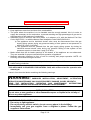
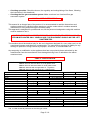
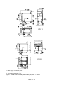
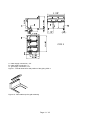
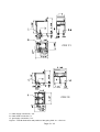
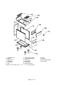
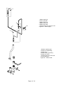
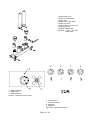
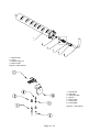
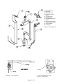
INSTALLATION, OPERATION AND SERVICE MANUAL
GAS COOKER
MODEL CPG
Page 1 / 18
CHAP 1 - INSTRUCTIONS TO PREVENT ACCIDENTS
Keep this manual carefully to be able to refer to it in every case of need.
• Keep appliance area clean and clear from combustibles.
• The place where the machine is to be installed must be enough aerated, this is in order to
supply the necessary air for combustion, to prevent reaching too high percentages of gas and to
aid evacuation of the products of combustion.
• Installation must be conform with local codes, or in absence of it, with the National Fuel Gas
Code, ANSI Z 223.1 or with the Natural Gas Installation Code CAN/CGA-B149.1
a) The appliance and its individual shutoff valve must be disconnected from the gas
supply piping system during any pressure testing of that system at test pressures in
excess of ½ psig (3.45 kPa).
b) The appliance must be isolated from the gas supply piping system by closing its
individual manual shutoff valve during any pressure testing of that system at test
pressures equal to or less than ½ psig (3.45 kPa).
• Make certain that the air intake openings in the bottom of the appliance are not obstructed.
They are essential for proper combustion and operation of appliance.
• Maintain adequate clearance in front of unit for servicing and proper operation. NOTE: All
servicing can be done through front door.
This equipment is to be installed to comply with the appliance Federal State or local plumbing
codes having jurisdiction.
THIS APPLIANCE IS EQUIPPED FOR NATURAL GAS, with orifices sized for operation with
natural gas.
Leave in front view the labels containing the following warnings:
WARNING:
IMPROPER INSTALLATION, ADJUSTMENT, ALTERATION,
SERVICE OR MAINTENANCE CAN CAUSE PROPERTY DAMAGE, INJURY OR DEATH.
READ THE INSTALLATION, OPERATING AND MAINTENANCE INSTRUCTIONS
THOROUGHLY BEFORE INSTALLING OR SERVICING THIS EQUIPMENT.
FOR YOUR SAFETY
Do not store or use gasoline or other flammable vapors or liquids in the vicinity of
this or any other appliance.
WHAT TO DO IF YOU SMELL GAS
• Do not try to light applance.
• Do not touch any electric switch; do not use any phone in the building.
• Immediately call your gas supplier from a neighbor’s phone. Follow the gas
supplier’s instructions.
Page 2 / 18
• If you cannot reach your gas supplier call the fire department.
CHAP 2 - INSTALLATION
2.1 Preliminary instructions
Installation must be carried out by following the instructions contained in this handbook and only by
a licensed tradesman in accordance with local codes, or in absence of it, with the National Fuel
Gas Code, ANSI Z 223.1 or with the Natural Gas Installation Code CAN/CGA-B149.1. The
manufacturer cannot be held liable for any damage caused by faulty installation.
The place where the machine is to be installed must have aeration equal to at least that
given in table 1.1, this is in order to supply the necessary air for combustion, to prevent
reaching too high percentages of gas and to aid evacuation of the products of combustion.
The installation room must be in conformity with the current fire regulations.
The unit must operate in a level position. Slight floor irregularities can be conpensated by turning
the adjustable feet of the cooker either clockwise or counterclockwise.
Clearances from combustible and noncombustible construction are given in table 1.2
model
CPG1
CPG2
CPG3
CPG7/1
CPG7/2
Power (BTU/hr)
60000 (13.2 kW)
120000 (26.4 kW)
180000 (39.6kW)
31000 (9kW)
62000 (18kW)
3
Air flow (m /h)
490
980
1470
315
630
Table 1.1 Minimum change of air in relation to the thermal power installed
Clearances
Side
Rear
Floor
Ceiling
Combustible construction
6.0 ”
6.0 ”
6.0 ”
Noncombustible construction
0“
0“
0“
48.0 ”
Table 1.2 Clearances from combustible and noncombustible construction
2.2 Handling and Unpacking
To move the machine to the place of installation, use a fork-lift truck. Do not drag the appliance on
the floor.Take the adhesive protection off the steel surfaces, taking care not to leave any
remains of glue, in which case use appropriate thinners to remove them.
2.3 Connecting to the water-main
The unit should be connected to your water supply by way of a water faucet. The water pressure
should fall between 14.5 and 72.5 PSI. If the water pressure is excessive, a pressure regulator
must be installed.
The pipe used to discharge the water must be heat resistant and allow for the free flow of the
discharge water. A funnel may be used between the unit discharge pipe and the floor drain but
tou should never restrict or reduce the diameter of the discharge pipe.
The following operations are to be carried out only by specialized technical personnel.
Having verified that available water system is adequate you can go ahead and make connection:
1. Clear the pipe of any ferrous waste by letting a certain amount of water flow through.
2. Place the cooker in the desired position and close to the water-main.
Page 3 / 18
3. Position the appliance level, adjusting the feet of the cooker.
4. Connect mains pipe to machine pipe (fig.1) using a mechanical filter and an interception cock.
5. Connect machine outlet pipe (fig. 1) to a suitable manifold that withstands high temperatures.
2.4 Connecting to the gas supply mains
Before connecting up the gas consult the gas board, all the installation and maintenance
operations should be carried out by the gas board or by authorized fitters. Make sure the
data of the rating plate correspond to the mains values. The rating plate is located at the bottom
of the screen-door panel.
Having verified that the gas supply system available is adequate you can go ahead with the
connection:
1. connect the mains pipe to the machine pipe (pos. G in fig.1) using a quick closing interception
cock which is easy to reach. You must use a pressure regulator to set the manifold
pressure as in tab. 4.1
2. Go ahead with setting up and adjusting as described in paragraph 2.4.1
3. Make all the checks listed below.
2.4.1 Setting up and adjusting
The first operation to carry out is to check the supply pressure, proceeding as follows:
1. Make sure the gas supply has been cut off.
2. Open the front door, unscrew the closing screw (pos. 9 in fig.6) of the pressure socket of the
supply pipe (pos. 1 in fig.6)
3. Connect a pressure gauge to the socket (e.g. a manometer)
4. Open the gas interception cock and measure the value of the supply pressure.
5. CAUTION: If the value of the supply pressure measured lies outside the interval shown in
table 2.2, it is not possible to go ahead with installation and it is necessary to inform the
gas board of the anomaly with the mains.
6. Close the gas interception cock, disconnect the pressure gauge, screw the closing screw back
on and close the front door.
Type of gas
Supply pressure Inches Water Column (kPa)
minimum
maximum
rated
3.5” (0.87)
10.5” (2.61)
7.0” (1.74)
natural gas (methane) G20
Tab. 2.2 Permissible limits for the gas supply pressure
After checking the supply pressure it is necessary to adjust the pressure at the nozzle, proceeding
as described below:
1. Make sure the gas supply has been cut off.
2. Take off the door by unscrewing the screw fixing it to the support.
3. Remove the water loading knob (1 di fig. 3) and unscrew the two screws fixing the instrument
panel to the under-panel. Remove the instrument panel taking care over the wire of the igniter.
4. Open the gas interception cock and ignite the burner flame by following the instructions of par.
5.2 positioning the knob onto the maximum position.
5. Adjuste the pressure regulator since the manifold pressure is 4” W.C.
6. Operate the appliance in the maximum conditions for at least 15 minutes, and then turn the
knob onto the minimum position.
7. Turn the minimum adjustment screw (pos. a in fig. 7) to obtain a reduced flame but sufficiently
stable and homogeneous.
8. Turn off the burner by following the instructions of par. 5.2, close the gas interception cock,
disconnect the pressure gauge, screw the closing screw back on and refit the instrument panel
and the front door.
2.4.2 Checks
For the purposes of operating safety it is essential to make the following checks:
∗ Checking air-tightness: Check there are no leaks in gas pipe using a solution of soap-water.
Page 4 / 18
∗ Checking operation: Check the burner, the regularity and extinguishing of the flame, following
the instructions in this handbook.
∗ Checking the flue gas evacuation system: Make sure there is a functional flue gas
evacuation system.
CHAP 3 - USER INSTRUCTIONS
This manual is an integral part of the product. It is recommended to read the instructions and
notices contained in it carefully before starting to use the cooker since it contains essential
information on using and servicing the machine safely.
This approach is desigated for professional use; All the personnel assigned to using this machine
must be trained to use it.
CAUTION: THIS UNIT HAS BEEN DESIGNED AND MADE TO BE USED TO COOK OR
STEAM WITH WATER ONLY. WHEN IN USE, THE EQUIPMENT SHOULD NOT BE LEFT
UNATTEMPTED.
The machine should be destined only for the use it has been designed for, every other use is to be
considered improper and therefore unreasonable. The manufacturer declines all liability for any
damage to persons or things caused by improper, erroneous, or unreasonable use.
Any tampering or modification to the appliance that has not previously been authorized by the
manufacturer frees the manufacturer from damage deriving from or referable to the above
mentioned acts.
CHAP 4 - SPECIFICATION
MODELS:
CPG 1: Gas unit with a single tank of 10.56 gallons.
CPG 2: Gas unit with two tanks of 10.56 gallons each.
CPG 3: Gas unit with three tanks of 10.56 gallons each.
CPG 7/1: Gas unit with a single tanks of 7.4 gallons.
CPG 7/2: Gas unit with two tanks of 7.4 gallons each.
TECHNICAL DATA
Length
Width
Height
Adjustable feet height
Weight
Tank capacity at maximum level
Gas supply mains connection
Water mains connection
Water outlet connection
Rated thermal power
Thermal power at minimum
Natural gas manifold pressure
Primary air adjustment
NOZZLE
main burner
pilot burner
minimum screw (bypass)
CPG1
CPG2
CPG3
CPG7/1
CPG7/2
35.4” (900 mm)
27.6” (700 mm)
17” (430 mm) 31.5” (800 mm) 47.2” (1200 mm) 15.7” (400 mm) 31.5” (800 mm)
34.4” (875 mm)
115..175 mm
65 Kg
101 Kg
144 Kg
50 Kg
93 Kg
10.6 gal (45 l) 10.6+10.6 gal 10.6+10.6+10.6 gal 7.4 gal (28 l)
7.4+7.4 gal
φ ½“
φ ½“
φ 1“
60000 BTU/hr 120000 BTU/hr
180000 BTU/hr
31000 BTU/hr
62000 BTU/hr
13000 BTU/hr 26000 BTU/hr
39000 BTU/hr
13000 BTU/hr
26000 BTU/hr
4” W.C.
FIXED
Natural gas G20
diameter (1/100 mm)
code
diameter (1/100 mm)
335
275
36
110161
36
adjustable
adjustable
Tab. 4.1 Main technical particulars of the CPG gas cooker
Page 5 / 18
CHAP 5 - PUTTING INTO OPERATION
5.1 Operations prior to starting
WARNING: if you do not follow these instructions exactly, a fire or explosion may
result causing property damage, personal injury or loss of life.
Make sure the basin is clean, otherwise clean it as described in paragraph 7.1
If you are using the cooker for the first time, you need to thoroughly clean all the parts that can
come into contact with foodstuffs. In this case, proceed as follows:
∗ Fill the basin with water and ordinary detergent.
∗ Put the machine into operation as described in the following paragraph.
∗ When the water is boiling, wait for a few minutes, and then turn off the flame as described in the
following paragraph.
∗ Open the door and drain by moving the lever inside into the open position.
∗ Rinse the basin carefully with clean water.
With ordinary use, the first thing to do is to load with water:
∗ Close the drain by moving the drain lever onto the closed position.
∗ Turn knob 1 of figure 3 anticlockwise.
∗ Wait for the basin to fill up to the top notch and then close the inlet cock by turning knob 1 of
figure 3 clockwise.
CAUTION: Do not leave the cooker in operation with no water in the basin.
When lighting the pilot follow these instructions exactly:
1. BEFORE LIGHTING smell all around the appliance area for gas. Be sure to smell next to the
floor because some gas is heavier then air and will settle on the floor. If you smell gas you must
follow the instructions placed in front view of the appliance.
2. Never use tools to push in or turn the gas the gas control knob. If it will not push in or turn by
hand , don’t try to repair it, call a qualified service technician. Force or attemped repair may
result in a fire or explosion.
3. Don’t use this appliance if any part has been under water, call a qualified service technician to
inspect the appliance and to replace any part which has been under water.
5.2 Lighting and shutdown instructions.
1. Carry out the procedures prior to putting the cooker into operation, given in the above
paragraph. CAUTION: fill the cooker basin with water up to the top reference notch.
2. Open the gas interception cock, located upstream of the machine.
3. Turn the knob of valve (pos.2 in fig. 3) onto the OFF position and wait 5 minutes to clear out any
gas. If you smell gas you must follow the instructions placed in front view of the appliance.
4. Turn the knob of the valve (pos.2 in fig. 3) onto the PILOT position(pos. 1 in fig. 3a). Open the
door.
5. Push the knob fully in and hold in, wait few seconds and put a flame near the ignition pipe (see
Fig. 5a) until the pilot flame ignites, which may be seen through the slot on the frame. Wait for a
few seconds and release the knob. If the flame fails to stay alight, repeat this opration.
ATTENTION : you mustn’t put the flame into the pipe, but only near the edge of ignition pipe.
6. Turn knob 2 of figure 3 onto a position between the minimum and maximum ones (2 and 3 of
fig. 3a), choosing the optimum value in relation to the quantity of product to be cooked.
7. Close the door and load the basket with the pasta to be cooked.
8. Wait for the water in the basin to boil.
9. Put the full basket into the basin, resting it on the edge and wait for the cooking time to elapse.
10.Remove the basket using the special handles.
Page 6 / 18
After cooking, turn off the main burner by turning knob 1 of figure 3 onto position 1 of fig. 3a and
turn off the pilot flame by turning it onto the off position (0 of fig. 3a), wait for at least five
minutes before draining off the water by moving the lever into the open position and finally
proceed with cleaning.
CAUTION: Remember to close the gas interception cock.
5.3 Instructions to prevent accidents
The personnel assigned to using the electric cooker must keep to the instructions specified in this
manual. If the operator has not been sufficiently well trained, operation will not be optimum and
the risks concerning safety will increase.
it is compulsory to:
∗
∗
∗
∗
∗
Fill the basin with water up to a level between the two notches.
Carry out all the routine maintenance and cleaning operations listed below.
Keep the surfaces that can come into contact with foodstuffs clean.
Make sure the gas pipes are always sound and well connected.
Service the burners periodically, at least once a year.
it is forbidden to:
∗
∗
∗
∗
Use the appliance dry.
Keep or place inflammable objects by the appliance.
Clean the machine using direct jets of water or high-pressure equipment.
Put your hands or other parts of your body into the water in the basin while the machine is in
operation, or when the cooker is switched off but with the water still hot.
∗ Use objects that are not suitable for contact with foodstuffs to contain the pasta to be cooked.
CHAP 6 - TROUBLE SHOOTING
CAUTION: For all the operations described below, close the gas interception cock and
turn to specialized and authorized personnel who have an adequate knowledge of the
functions of the various parts and of the precautions to be taken.
Below are listed some possible malfunctioning and the likely cause and remedy, if the problem is
not solved or is not contemplated for in the following table, call our customer technical service :
MALFUNCTIONING
The pilot burner will not
ignite
LIKELY CAUSE
∗ malfunctioning of the spark plug
∗ insufficient pressure at the pilot
burner
The pilot burner goes
out as soon as the knob
is released
∗ The pilot burner does not sufficiently
heat the thermocouple
∗ insufficient pressure at the valve
The main burner will not
ignite even if the pilot
burner is ignited
∗ insufficient pressure at the burner
REMEDY
∗ Check the spark plug fixing
∗ Check the cable and the connections
with the igniter and the spark plug
∗ Check the igniter and the spark plug
and replace them if necessary.
∗ Check the supply pressure (§ 2.4.1)
∗
∗
∗ Repeat the operation, pressing the
valve knob in more fully
∗ Check the relative position of the
pilot and of the thermocouple.
∗
∗
Page 7 / 18
Check the supply pressure (§ 2.4.1)
∗ Check the valve
∗ Check the supply pressure and the
pressure at the nozzle (§ 2.4.1)
∗
∗
∗ burner holes clogged
Check the nozzle and clean it or replace
it if necessary.
Check the valve
Check the valve
Check the nozzle and clean or replace it
if necessary.
Clean the burner.
CHAP 7 - CLEANING AND MAINTENANCE
Routine maintenance consists of daily cleaning all the parts that can come into contact with
foodstuffs and of the periodical maintenance of the burners, nozzles and of the outlet pipes.
The instructions to be followed for cleaning are listed below:
∗ Use a soft cloth and neutral detergents.
∗ To clean the stainless steel, do not use steel wool, iron scrapers or brushes since they can
deposit ferrous particles that on oxidizing lead to rust. To remove hardened residues, use
wooden or plastic spatulas, or stainless steel wool.
∗ If you use alkaline detergents, thoroughly rinse after washing.
∗ Do not spray with direct jets of water or with high-pressure equipment since any water getting
into the outer shell can jeopardize the safety of the machine.
∗ Periodically check whether any incrustations have formed in the overflow pipe (due to foam)
and clean it if necessary, without using objects that can damage the rubber pipe.
∗ When not being used, do not leave water in the basin.
When the appliance is not to be used for lengthy periods, spread a protective film over all the
stainless steel surfaces by passing a cloth soaked in Vaseline oil over them, and air the rooms
periodically.
The periodical annual maintenance of the burners must be done by specialized and
authorized personnel and it consists of keeping the holes clean for the fuel-comburent mixture
to flow in and out. Access to the burners and nozzles is explained in the following paragraphs.
7.1 Special maintenance
The special maintenance procedures should be carried out by qualified and authorized personnel,
possibly by means of the technical service of the manufacturer of the component requiring
servicing.
CAUTION: it is recommended to use only genuine spare parts, in compliance with the same
technical specifications as the ones replaced.
CAUTION: in any case, before starting, the gas interception cock located upstream
of the appliance has to be closed.
7.1.1 Replacing the main burner
1. After making sure you have cut off the gas supply, open the door and unscrew the two screws
fixing the burner to the framework.
2. Unscrew the two nuts fastening the valve pipe to the burner (pos. 3 and 4 of fig. 4), and remove
the pipe (pos. 1 of fig. 4).
3. Remove the burner and replace it with the new one, taking care to insert the end of the burner
into the hole from the other side of the frame.
4. Screw the two screws, for fixing to the frame, back on and fit the pipe connecting the valve to
the burner. After these operations it is necessary to check the seal of the gas circuit.
7.1.2 Replacing the pilot burner
Page 8 / 18
1. After making sure you have cut off the gas supply, open the door and unscrew the two screws
fixing the pilot burner to the framework.
2. Unscrew the nuts fastening the thermocouple, the spark plug and the pipe of the pilot burner
(pos.7 of fig.5). Caution, in doing this keep the pilot unit on the inside of the framework, inserting
your hand from beneath.
3. Replace the pilot burner and the other defective parts of the assembly.
4. Screw the two screws, for fixing to the framework, back on and fit the pipe, thermocouple and
spark plug.
After these operations it is necessary to check the seal of the gas circuit and the efficiency
of the pilot burner.
7.1.3 Replacing the valve cock
1. After making sure you have cut off the gas supply, remove the door by unscrewing the screw
fixing it to the support.
2. Remove the water inlet knob (1 of fig. 3) and unscrew the two screws fixing the instrument
panel to the under-panel. Remove the instrument panel.
3. Disconnect from the valve the supply pipe, the pipe that goes to the burner and the one that
goes to the pilot burner and the thermocouple (pos. 1,4, 6 and 5 of fig. 6).
4. Disconnect the valve from the under-panel by unscrewing the two screws fixing it and replace it
with the new one.
5. Reconnect the gas pipes and the thermocouple in the same positions as before.
6. Refit the instrument panel with the two screws taken out beforehand, fit the water knob onto the
relative shaft and fix the front door to the support.
After these operations it is necessary to check the seal of the gas circuit, the efficiency of
the pilot burner and to repeat the adjustment operations.
FIGURES
Page 9 / 18
CPG 1
CPG 2
A - water supply connection φ 1/2”
B - water outlet connection φ 1”
G - gas supply connection φ 1/2”
Figure 1 - Overall dimensions and position of the piping CPG 1 – CPG 2
Page 10 / 18
CPG 3
A - water supply connection φ 1/2”
B - water outlet connection φ 1”
G - gas supply connection φ 1/2”
Figure 1 - Overall dimensions and position of the piping CPG 3
Figure 1b - Removable top flue grid assembly
Page 11 / 18
CPG 7/1
CPG 7/2
A - water supply connection φ 1/2”
B - water outlet connection φ 1”
G - gas supply connection φ 1/2”
Figure 1 - Overall dimensions and position of the piping CPG 7/1 – CPG 7/2
Page 12 / 18
1. Adjustable foot
7. Flue gas outlet grille
2. Bottom
8. Foam collection grille
3. Right panel
9. Outlet grille
4. Left panel
10.Under-panel
5. Rear panel
11. Front panel
6. Top
12. Water inlet knob
Figure 2 - Gas cooker CPG 1 – 2 – 3 – 7/1 - 7/2 components
Page 13 / 18
14. Door
15. Magnet
16. Door support plate
18. Door pivot
1 Water supply jet
2 Cock to jet pipe
3 Water inlet cock
4 Water inlet knob
6 Water knob disk
7 Copper pipe from supply to cock
Figure 2a – Water supply
1 Rubber overflow pipe
3 Outlet-cock pipe fitting
4 Outlet cock
5 Outlet-rubber pipe fitting
6 Outlet cock lever
7 Copper pipe from cock lever
8 Lever extension
Figure 2b – Water outlet
Page 14 / 18
1 Double pipe union
3 Outlet-cock pipe fitting
4 Outlet cock
5 Outlet-rubber pipe fitting
6 Outlet cock lever
7 Copper pipe from cock to jet
8 Lever extension
9 Rubber overflow pipe
Figure 2b – CPG 2 – CPG 7/2
water outlet
1 - Water inlet knob
2 - Safety valve
3 - Valve reference
Figure 3 - Instrument control panel
0 - Closed valve
1 - Open pilot burner
2 - Minimum
3 - Maximum
Figure 3a - Valve knob positions
Page 15 / 18
1. Main burner
2. Union
3. Nozzle fixing nut
4. Main nozzle
Figure 4 - Main burner
1.
3.
4.
5.
6.
7.
8.
Pilot burner
Gas pipe
Thermocouple
Spacer
Pilot nozzle
Fixing nuts
Fixing plate
Figure 5 – Pilot burner
Page 16 / 18
1.
2.
3.
4.
Gas supply pipe
Brass nut
Brass twin-cone
Pipe from valve to
burner
5. Thermocouple
6. Pilot gas pipe
7. Pilot pipe-valve union
8. Valvle
9. Pressure tube screw
10. Pressure tube washer
11. Fixing washer
12. Fixing nut
Figure 6 - Gas supply unit
Figure 5a – Manual ignition
A. Minimum adjustment screw
Figure 7 - Safety valve
Page 17 / 18