1
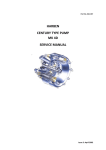
GRAIN EXTRACTOR
EXG 300
User’s Manual
Operation, Maintenance
and Spare Parts
Code: 187000
Edition: June 2010
Review:
2010/004_1
Due to the continuing improvements in the design and
manufacture of AKRON® products, MICRÓN FRESAR
S.R.L. reserves the right to modify components and/or
specifications without prior notice.
EXG 300 GRAIN EXTRACTOR
1. INTRODUCTION
The present user’s manual describes the functions and components of the AKRON® grain
extractor model EXG 300. It gives detailed
safety instructions and provides recommendations for its operation, also offering a general
maintenance guide for the machine.
The information provided in this manual is fundamental for the efficient and safe operation of
the machine. This documentation is included
with the machine in order to guarantee its optimal operation. That is why this manual should
be available at all times either together with the
machine or at least within the operators' and
supervisors' reach.
1-a. The Purpose of the Machine
The EXG 300 grain bag unloader has been
designed to safely unload grain and oilseeds
that have been stored in chamber conditions in
standard grain bags during the recommended
period for each grain type, and store them in
grain carts or tucks.
The simple concept of design of this machine
requires very little maintenance and ensures a
good operation under different conditions.
However, it is important to highlight that this
grain extractor is exclusively designed to work
with grain bags, and that the warranty will be
valid as long as the machine is used according
to the instructions for use detailed in this
manual.
Before operating, servicing or repairing this
machine, the instructions given in the present
manual and in any other documentation supplied by the manufacturer must be followed.
Special attention must be paid to safety precautions and recommendations, and to compliance
with the pertinent local Occupational Health &
Safety laws in force.
Any arbitrary modification carried out on the
machine or its components will release the
manufacturer from any responsibility arising
from damage or injury that may occur as a result
of such modification.
5
EXG 300 GRAIN EXTRACTOR
7
2. GENERAL INDEX
1. Introduction . . . . . . . . . . . . . . . . . . . . . . . . . . . . . . . . . . . . . . . . . . . . . . . . . . . . . . . . . . . . . . . . .5
1-a The Purpose of the Machine . . . . . . . . . . . . . . . . . . . . . . . . . . . . . . . . . . . . . . . . . . . . . . . . . . .5
2. Index. . . . . . . . . . . . . . . . . . . . . . . . . . . . . . . . . . . . . . . . . . . . . . . . . . . . . . . . . . . . . . . . . . . . . . .7
3. Safety . . . . . . . . . . . . . . . . . . . . . . . . . . . . . . . . . . . . . . . . . . . . . . . . . . . . . . . . . . . . . . . . . . . . . .9
3-a Attitude Toward Safety . . . . . . . . . . . . . . . . . . . . . . . . . . . . . . . . . . . . . . . . . . . . . . . . . . . . . . . .9
3-b "ATTENTION" Symbol and Signal Words . . . . . . . . . . . . . . . . . . . . . . . . . . . . . . . . . . . . . . . . .9
3-c Personal Protective Equipment . . . . . . . . . . . . . . . . . . . . . . . . . . . . . . . . . . . . . . . . . . . . . . . . .9
3-d Safety Warnings . . . . . . . . . . . . . . . . . . . . . . . . . . . . . . . . . . . . . . . . . . . . . . . . . . . . . . . . . . . .9
3-e Risk Analysis . . . . . . . . . . . . . . . . . . . . . . . . . . . . . . . . . . . . . . . . . . . . . . . . . . . . . . . . . . . . . . .9
4. Receiving the Machine . . . . . . . . . . . . . . . . . . . . . . . . . . . . . . . . . . . . . . . . . . . . . . . . . . . . . . .13
4-a. Grain extractor identification . . . . . . . . . . . . . . . . . . . . . . . . . . . . . . . . . . . . . . . . . . . . . . . . . . .13
4-b. Contact Information . . . . . . . . . . . . . . . . . . . . . . . . . . . . . . . . . . . . . . . . . . . . . . . . . . . . . . . . .13
4-c. Operating Principle . . . . . . . . . . . . . . . . . . . . . . . . . . . . . . . . . . . . . . . . . . . . . . . . . . . . . . . . . .14
5. Preparation and Setup . . . . . . . . . . . . . . . . . . . . . . . . . . . . . . . . . . . . . . . . . . . . . . . . . . . . . . .15
5.a Requerimientos de accionamiento . . . . . . . . . . . . . . . . . . . . . . . . . . . . . . . . . . . . . . . . . . . . . .15
5.b Position changes . . . . . . . . . . . . . . . . . . . . . . . . . . . . . . . . . . . . . . . . . . . . . . . . . . . . . . . . . . .15
5.c Recommendations to Make Extraction Easier . . . . . . . . . . . . . . . . . . . . . . . . . . . . . . . . . . . . .17
5.d Previous Controls on the Machine . . . . . . . . . . . . . . . . . . . . . . . . . . . . . . . . . . . . . . . . . . . . . .17
5.e Machine Layout . . . . . . . . . . . . . . . . . . . . . . . . . . . . . . . . . . . . . . . . . . . . . . . . . . . . . . . . . . . . .17
5.f Grain Bag Preparation . . . . . . . . . . . . . . . . . . . . . . . . . . . . . . . . . . . . . . . . . . . . . . . . . . . . . . . .18
5.g Final Adjustments on the Machine . . . . . . . . . . . . . . . . . . . . . . . . . . . . . . . . . . . . . . . . . . . . . .19
6. Set up for extraction . . . . . . . . . . . . . . . . . . . . . . . . . . . . . . . . . . . . . . . . . . . . . . . . . . . . . . . . .21
6.a. General Comments on the Storage in Grain bags . . . . . . . . . . . . . . . . . . . . . . . . . . . . . . . . . .21
6-b Operation Start-up . . . . . . . . . . . . . . . . . . . . . . . . . . . . . . . . . . . . . . . . . . . . . . . . . . . . . . . . . . .22
6-c Operation Parameters . . . . . . . . . . . . . . . . . . . . . . . . . . . . . . . . . . . . . . . . . . . . . . . . . . . . . . . .23
6-d Protection against Overloads . . . . . . . . . . . . . . . . . . . . . . . . . . . . . . . . . . . . . . . . . . . . . . . . . .24
6-e Interruptions during Extraction . . . . . . . . . . . . . . . . . . . . . . . . . . . . . . . . . . . . . . . . . . . . . . . . .24
6-f Extraction at the End of the Bag . . . . . . . . . . . . . . . . . . . . . . . . . . . . . . . . . . . . . . . . . . . . . . . .24
6-g Unwinding the Bag . . . . . . . . . . . . . . . . . . . . . . . . . . . . . . . . . . . . . . . . . . . . . . . . . . . . . . . . . . .25
7. Maintenance Program . . . . . . . . . . . . . . . . . . . . . . . . . . . . . . . . . . . . . . . . . . . . . . . . . . . . . . . .27
7-a Maintenance Schedule . . . . . . . . . . . . . . . . . . . . . . . . . . . . . . . . . . . . . . . . . . . . . . . . . . . . . . .27
7-b. Maintenance after Receiving the Machine . . . . . . . . . . . . . . . . . . . . . . . . . . . . . . . . . . . . . . . .27
7-c Desmantelamiento de piezas para su reparación . . . . . . . . . . . . . . . . . . . . . . . . . . . . . . . . . . .27
7-d Lubrication . . . . . . . . . . . . . . . . . . . . . . . . . . . . . . . . . . . . . . . . . . . . . . . . . . . . . . . . . . . . . . . . .28
7-e Prevention of Wear on Flexible Pipes . . . . . . . . . . . . . . . . . . . . . . . . . . . . . . . . . . . . . . . . . . . .28
7-f Tire Change . . . . . . . . . . . . . . . . . . . . . . . . . . . . . . . . . . . . . . . . . . . . . . . . . . . . . . . . . . . . . . . .28
8
EXG 300 GRAIN EXTRACTOR
8. Machine Transportation and Storage . . . . . . . . . . . . . . . . . . . . . . . . . . . . . . . . . . . . . . . . . .29
8-a Preparation of the Machine for Transportatione . . . . . . . . . . . . . . . . . . . . . . . . . . . . . . . . . . . .29
8-b Transportation . . . . . . . . . . . . . . . . . . . . . . . . . . . . . . . . . . . . . . . . . . . . . . . . . . . . . . . . . . . . . .30
8-c Machine Storage . . . . . . . . . . . . . . . . . . . . . . . . . . . . . . . . . . . . . . . . . . . . . . . . . . . . . . . . . . .31
8.d. Extractor Parking . . . . . . . . . . . . . . . . . . . . . . . . . . . . . . . . . . . . . . . . . . . . . . . . . . . . . . . . . . .31
9. Specifications . . . . . . . . . . . . . . . . . . . . . . . . . . . . . . . . . . . . . . . . . . . . . . . . . . . . . . . . . . . . . . .33
10. Product Dismantling and Disposal . . . . . . . . . . . . . . . . . . . . . . . . . . . . . . . . . . . . . . . . . . .35
11. Guarantee Terms . . . . . . . . . . . . . . . . . . . . . . . . . . . . . . . . . . . . . . . . . . . . . . . . . . . . . . . . . . .37
12. Alphabetical Index . . . . . . . . . . . . . . . . . . . . . . . . . . . . . . . . . . . . . . . . . . . . . . . . . . . . . . . . . .39
13. Spare Parts List . . . . . . . . . . . . . . . . . . . . . . . . . . . . . . . . . . . . . . . . . . . . . . . . . . . . . . . . . . . .41
13-a Information for Obtaining Spare Parts . . . . . . . . . . . . . . . . . . . . . . . . . . . . . . . . . . . . . . . . . . .41
14.Parts subject to normal wear and tear . . . . . . . . . . . . . . . . . . . . . . . . . . . . . . . . . . . . . . . .69
15. User’s Notes . . . . . . . . . . . . . . . . . . . . . . . . . . . . . . . . . . . . . . . . . . . . . . . . . . . . . . . . . . . . . . .71
EXG 300 GRAIN EXTRACTOR
9
3. SAFETY
3-c. Personal Protective Equipment
Even though the machine's operation is simple
and safe, it is essential that all grain cart loading,
unloading and transport operators and supervisors have an in-depth knowledge of the contents
of this user's manual. In this way, situations of
danger will be avoided for the operator, for third
parties and for goods in the surrounding area.
Micrón Fresar S. R. L. recommends the use of
the following Personal Protective Equipment in
order to avoid any possible injury:
There must be a written record of when the operators are trained in every detail of the machine's operation.
3-a. Attitude Toward Safety
Just as with the operation of any other machine,
the most important factor for preventing accidents of any kind is the positive attitude of operators and supervisors toward safety. As well as
following the manufacturer's recommendations,
the habit must be developed of foreseeing and
analyzing every possible contingency that could
arise during the operation of the machine. Even
though it is impossible to foresee all possible
situations, this habit helps to prevent the majority of hazardous situations.
3-b. "ATTENTION" Symbol and Signal
Words
Throughout the present manual, the
"Attention" symbol is used to indicate
risk situations for the operator, the
machine, other equipment or other people.
This symbol will appear together with certain signal words depending on the relative seriousness
of each risk situation.
DANGER: This identifies an imminent hazardous situation whose consequences may
cause death or serious injuries if not avoided.
WARNING: This identifies a potential hazardous situation whose consequences may
cause death or slight to moderate injuries if not
avoided.
IMPORTANT: This describes a particular
situation where the machine could be damaged or its normal operation could be affected.
Personal Protective Equipment
Situation
Tractor
driver
Machine
operator
3-d. Safety Warnings
On different parts of the machine and on its
accessories you will find decals with accident
prevention symbols, which must be considered
as part and extension of the instructions detailed
in this manual. Special care must be taken to
ensure these decals are present and legible
during the entire working life of the machine.
If for any reason any of these gets lost or becomes illegible through wear, it is important to
substitute it immediately indicating its corresponding code. To ask for a replacement decal,
please contact either the manufacturer using the
information given in 4-b. "Contact information",
or your local Technical Representative.
3-e. Risk Analysis
The risk situations that typically arise during the
operation of this machine are detailed below.
Recommendations are made that are of vital
importance for the safety of the machine operators, of other workers nearby, and the machine
itself.
The pictograms used are taken from IRAM standard 8075 "Tractors, agricultural and forestry
and green space maintenance machinery Safety signs and hazard pictograms - General
principles and features". For more details, their
location on the machine is shown in the following picture.
EXG 300 GRAIN EXTRACTOR
10
DECALS
#
1
2
3
4
5
6
7
IMAGE
CODE
NAME
Risk situations:
• During machine transport
114138
Particular recommendations:
• When transporting the grain cart, stay below the speed limit for safety reasons.
Risk situations:
• During machine transport, During the discharge process
114200
Particular recommendations:
• Do not climb or travel on the machine structure.
Risk situations:
• During the discharge process
114181
Particular recommendations:
• Keep a safe distance away from the machine.
Risk situations:
• When operating the machine
016135 Particular recommendations:
•Observe the warnings indicated in the pictogram in order to avoid accidents.
Risk situations:
• When operating the machine or performing maintenance tasks
114112 Particular recommendations:
• Carefully read the operator's manual so as to become acquainted with its features and operation.
Risk situations:
• When performing maintenance tasks.
Particular recommendations:
114122
• Stop the engine and remove the key before performing maintenance or preparation tasks.
-
NOTICE
QTY
1
1
1
1
1
1
1
8
080112/
Roll rotation direction in operation mode.
110
1
9
065822 Cardan coupling position
1
10
114186 Tying for transport
2
11
12
13
14
15
Risk situations:
• During the discharge process
114152
Particular recommendations:
• Do not open or take away the safety protections while the motor is running.
Risk situations:
• When handling the hydraulic circuit.
114178 Particular recommendations:
• Check circuit for proper operation.
• Check flexible pipes' condition.
Risk situations:
• when handling the roll.
187139
Particular recommendations:
• Avoid hand crushing when turning the roll into operating position.
Risk situations:
• when handling the roll.
187140
Particular recommendations:
• Avoid arm crushing while the roll is operating.
187132 Switch valvle.
1
1
1
1
1
EXG 300 GRAIN EXTRACTOR
#
IMAGE
11
CODE
NAME
QTY
16
Risk situations:
• During the discharge process.
114162 Particular recommendations:
• Do not stand within reach of the auger or introduce your hand while the motor
is running.
1
17
180108 Cutting blade.
1
18
Risk situations:
• Machine tune-up.
182130
Particular recommendations:
• Caution during the operation process.
1
19
•Risk situations:
When transporting the machine.
180100
•Particular recommendations:
Avoid contact with power lines, especially when the auger tube is unfolded.
1
20
135133 End of bag.
20
21
014128 Maximum 540 rpm.
1
22
Risk situations:
• When operating the machine or performing maintenance tasks.
• During the process of grain discharge.
114132 Particular recommendations:
• Never use the driveshaft without its protector.
• Never cross over the driveshaft while it is coupled.
• Use, maintain or repair the coupling according to.
1
23
114290 Identification plate.
1
24
065823/ Machine's side - cod. 065824.
824 Tractor's side - cod. 065823.
1
25
180129 Roll coupling and uncoupling.
1
26
187134 Maintenance.
1
27
187135 Maintenance.
1
28
187138 Transport/ Operating height shims.
1
29
187141 Mechanical jack.
1
30
180127 Flow control valve.
1
31
180122 Maintenance.
1
32
33
087136
Patent Pending
087137
1
34
087195 Reflective triangle
1
12
See inside
EXG 300 GRAIN EXTRACTOR
EXG 300 GRAIN EXTRACTOR
4. RECEIVING THE MACHINE
13
This information is engraved on the identification
plate, which is located as shown in Figure 4.1
above.
The grain extractor AKRON® modelo EXG 300
is delivered almost ready for operation.Only a
number of verifications related to transport
issues must be taken into account upon receiving the machine.
1) If the machine is delivered on a truck or other
vehicle, special care must be taken to remove all
the elements used to fix the machine to the
transport vehicle.
2) If the machine is delivered in tow, running on
its own wheels, the pressure of the wheels must
be checked to be at a reasonable level.
4.1. Identification plate location
3) In both cases, the machine’s paint and structure must be checked to be free from damages
that could have taken place during transport. If
that were the case, it would be convenient to
assess if the damage could influence the machine’s normal operation or if its integrity could be
affected in the future.
4) All the machine components must be checked
to be present and in good operating conditions
and all the mechanisms should be operative.
5) All the safety guards and protections should
be present and in good conditions (e.g., the lifting auger lock pin, the drawbar cover, etc.)
Please fill in your machine's data here for your
records:
MODEL:
MASS (KG):
4-a. Identification of your Self-unloading
Grain Cart
When ordering replacement parts or requesting
technical assistance or information, always provide the following details for product identification purposes:
• Model
• Mass (kg)
• Serial #
SERIAL #:
NOTA: The data, specifications and illustrations
in this manual are based on the information
available at the time it was written.
Due to the continuing improvements in the
design and manufacture of AKRON® products,
MICRÓN FRESAR S.R.L. reserves the right to
modify components and/or specifications
without prior notice.
Figures are only for illustration purposes, no
measures should be taken on the drawings.
4-b. Contact Information
Should you need any further explanation regar-
14
ding the contents of this manual, please contact
us:
Micrón Fresar S.R.L.
Rosario de Santa Fe 2256
X2400EFN - San Francisco (Córdoba)
ARGENTINA
Tel.: ++54 3564 435900 (rollover lines)
Toll free 0 800 333 8300 (in Argentina)
e-mail: [email protected]
www.akron.com.ar
4-c. Operating Principle
The main functions of the machine are described below, as well as the elements used to perform each of them.
Function
Related component
or system
Fastening System
Roll Pins
Grain Bag winding up
Roll driven by a hydraulic
motor.
Auger driven by a tractor
power take-off (PTO).
Grain bag longitudinal cut
(slash) during motion.
Cutting blade
End of Bag
Load speed-up Pusher
(Grain Pusher System) driven by a hydraulic motor.
Unwinding
Roll driven by a hydraulic
motor.
EXG 300 GRAIN EXTRACTOR
EXG 300 GRAIN EXTRACTOR
5. PREPARATION AND SETUP
15
ying with the maximum transportation width allowed.
5-a. Operation Requirements
WARNING: Do not travel on the machine
Requiring as little human effort as possible is
one of the most important premises for the
machine’s design, as well as attaining the best
possible comfort level for the operator.
To operate the equipment it is necessary to use
a tractor with a minimum of 90 HP. Of this vehicle, both its 540 rpm power take-off (PTO) and
its oleo-hydraulic system are used, the former
for driving the grain augers and the latter mainly
for winding up the grain bag. This way, the tractor’s traction system remains free, which avoids
an excessive wear of the clutch.
In the following figure, the main features of both
positions can be compared. It can be observed
that during transport position the lifting tube is
folded and the roll is practically parallel to the
chassis.
Special care must be taken not to use a tractor
with a power rating far greater than the recommended figure, and the front wheels should be
plain, not studded. Pulling a heavier tractor
would cause excessive efforts on the extractor’s
structure and components.
Figure 5.1:Operating position
WARNING: Maximum transport speed
30km/h (19 mph).
5-b. Position changes
The AKRON EXG 300 mechanical grain
extractor can be set in two possible configurations: an operating position and a transport position. The transport position allows the machine
to be taken in tow by a pick-up or tractor, compl-
Figure 5.2:Transport position
Change from Transport Position to Operating Position
Instruction
Link the extractor to the operating vehicle. Then, connect
the hydraulic circuit together
with the power take off.
Once the machine has been
coupled to the tractor, place
the mechanical legs into
transport position.
Action
Obs.
16
Instruction
Action
EXG 300 GRAIN EXTRACTOR
Obs.
Take the sweep auger ends from
transport position and place them
into working position, taking into
account the turning direction.
Unhook the roll by pulling up the
latch located at the front part of the
chassis, and make it turn until reaching its transverse position; put the
supporting arm down in order to lock
it.
Warning
Avoid hand crushing when
turning the roll into operating
position.
Remove the lock pin of the superior
tube support and activate the
“Auger” hydraulic control until the
tube is completed unfolded.
Cut the bag manually and open the
cut, leaving the grain at sight (as
shown in the figure).
Check that the blade is aligned with
the cut made manually in order to
continue cutting. Remove the blade
cover to start working.
Activate the "Roll” control.
With the tractor, take the machine
backwards, as centered as possible, and hook the bag to the roll by
causing the roll to rotate.
Activate the “Height” control to
adjust the operating height.
Once again activate the “roll” control
to start operating.
Warning
Check that the blade cover
protects the blade while the
machine is not operating.
Warning
Avoid arm crushing while the
roll is operating.
Warning
When operating the mechanical
parts, care must be taken so as
to avoid injuries used by trapping.
EXG 300 GRAIN EXTRACTOR
17
5.c Recommendations to Make
Extraction Easier
The bagging machine AKRON® model E 9250
FH Y FHH / E 9250 D has the grain extractor
AKRON® model EXG 300 as an ideal complement, and the extractor requires some conditions in the layout and preparation of the grain
bags.
If a grain bag is prepared next to a wire fence, a
4-metre clearance must be kept, taking into
account that the extractor loads a vehicle
moving along to the right-hand side from theº
point of view of the tractor driver.
Fence
Grain bag
Min
4m
5.d Previous Controls on the Machine
Before setting up the machine for the extraction
process the following controls will have to be
carried out:
Make sure that all the parts of the machine are
prepared according to its operating position, as
indicated in Section 4 – “Position changes”
Check the oil level in all the machine’s drive and
transmission gearboxes. The detail of their components is given in section 9. “Assemblies”.The
machine should never be operated if there is not
enough oil inside all the gearboxes, since this
would result in serious mechanical damage to all
these transmission components.
In all cases, if it were necessary to add oil, only
SAE 90 must be used. The quality of the oil
should never be altered, since this would result
in problems for the performance and lifespan of
the gearbox components
5.e Machine Layout
Figura 5.3 Location of a grain bag in relation to a wire fence
If two or more grain bags have to be placed
parallel one to the other, at least 1 (one) metre
should be left between them in order to work
with room to spare during the extraction.
However, the most important precaution is to
anticipate that the first bag can be easily accessed from the side where the grain transport vehicle must move.
Once the extractor is ready in its operating
position, it must be placed facing the grain bag
in the following way:
1)1Align the extractor with the tractor and the
grain bag as shown in the figure. These three
elements should be as centred and aligned as
possible, since this will make the extraction operation easier.
Min.
GRAIN
BAG
SILO BOLSA
Figura 5.4 Transversal section of two silage bags located parallel
to each other.
If the grain bag is closed on its initial end using
two pieces of wood or plastic seals, less remaining cereal will be left to remove manually at the
end of the extraction process.
Figure 5.5 Implements alignment
2) Remove the lock pin that keeps the lifting
auger attached to the cassis. To prevent this pin
from getting lost during the machine operation, it
is highly advisable to put it in the same place
(tube support for transport position), which is
free at that moment.
3) Make sure that the hydraulic switch valve is in
the "Auger” position.
EXG 300 GRAIN EXTRACTOR
18
3) Activate the "Auger” control.
Figure 5.6 Switch valve lever into “TUBE” position.
4) Clear the area below the tube.
5) Lift the tube to its operating position using the
tractor’s hydraulic system. Check that no person
or equipment interferes with the tube in order to
prevent dangerous trapping or hitting risks.
1) The bag must be opened with extreme care,
since any longitudinal slash on the bag’s top, the
most stretched part of it, could result in the bag
opening completely. To avoid such risk, it is advisable to work according to the following procedure:
1.1) Make a short transversal cut, about 20 cm long,
about 2 m from the end of the bag. This cut will be
more or less at the same height as the extractor’s
cutting blade.
TRANSVERSAL
CUT
6) 6) Activate the “Roll” control when it is necessary to start operating.
WARNING: During operation and transport, keep away from and avoid travelling
on the machine.
GRAIN BAG
20 cm
2m
Figure 5.8 Bag transverse cut
1.2) From the middle of the previous cut, slash the
grain bag longitudinally up to its end.
LONGITUDINAL
CUT
GRAIN BAG
2m
Figure 5.9 Bag longitudinal cut
1.3) Open this last cut to the sides, so that the cereal shows.
Figure 5.7 Switch valve lever into “ROLL” position.
5-f. Grain Bag Preparation
If it is possible to choose, it is always more convenient to start extracting grain from the end of
the grain bag where the storage was finished,
since there is enough bag left in this end to fix to
the machine’s roll.If this option is not available,
the operation can also be started from the initial
end of the grain bag (see the paragraph 5-b.
“Recommendations to make extraction easier”).
In both cases, starting from the initial or final
end, the grain bag has to be opened as explained below. However, when the extraction starts
from the initial end, some grain will have to be
removed manually until enough grain bag material is left to fix to the extractor’s roll. Follow the
instructions given in title 6-e. “Extraction at the
end of the grain bag” for manual grain extraction
OPEN
GRAIN BAG
Figure 5.10 Bag opening
2) If there is not enough material to fix the grain
bag to the extractor’s roll, it is convenient to
extract some of the cereal manually, using shovels, until enough plastic is available. Most of
the times, this operation will be unavoidable
when the extraction starts from the same end
where the storage was started.
3) Make sure there are no people or gear around
the area in order to avoid any kind of damage.
Reverse the machine using the tractor until the
cereal starts to cover the horizontal augers.It is
important to avoid exerting too much pressure
EXG 300 GRAIN EXTRACTOR
19
on the cereal mass, since this may result in
excessive, unnecessary efforts on the extractor.
4) Make sure that the machine’s cutting blade is
aligned with the cut previously made by hand.
The cutting blade’s cover will have to be lifted to
this effect.
3) Pierce both sides of the end of the grain bag
with each of the roll teeth, as shown in figure
5.14.
Piece the
grain bag
WARNING: Ceck that the cutting blade
cover protects the blade while the machine is not operating.
Tractor’s
side
Flow Control Valve
Figure 5.14 – Bag Perforation
Grain bag
figure 5.11 Close
(clockwide)
Figure 5.12 Open
1/2 Turn
(counterclockwide)
Tractor’s
side
5-g. Final Adjustments on the Machine
First of all, the cardan shaft should not be operated before the grain bag is fixed to the
Otherwise, the augers would start moving and
the grain bag could get entangled in them.
Completely close the flow control valve, and
then open it half a turn, that is, 180º.
1) Turn the roll using the tractor’s hydraulic
system until the roll teeth reach the position
shown in the figure 5.13
2) To fix the bag to the roll, both the upper and
lower sides of the bag should easily reach the
whole breadth of the roll at the height of its teeth.
Upper side of
the grain bag
Figure 5.15 secure the bag on the roller teeth.
4) Check once again that the machine’s cutting
blade is aligned with the cut previously made on
the top of the bag.If the cut on the grain bag
were not continued normally, the extractor would
be subjected to excessive efforts and the grain
bag would run the risk of being torn.
If the cutting blade stops cutting, a small transversal (figure 5.16) cut must be made on the
grain bag in order to align it with the blade by
means of a longitudinal cut as shown in the following figure 5.17.
Roll
Teeth
CUTTING
BLADE
Tractor’s
side
TRANSVERSAL
CUT
GRAIN BAG
Lower side of
the grain bag
Figure 5.13 - Location of the roll teeth
Figure 5.16 - Transversal cut
20
LONGITUDINAL
CUT
Figure 5.17 – Longitudinal Cut
Figure 5.18 Cut Extension
EXG 300 GRAIN EXTRACTOR
EXG 300 GRAIN EXTRACTOR
6. SET
UP FOR
21
EXTRACTION
6-a.General Comments on the Storage in
Grain bags
The storage of dry grain in grain bags is commonplace among rural producers, who regard
this system for the conservation of grains to be
flexible and economical, since important product
commercialisation costs can be eliminated as
regards the storage carried out by third parties.
Figure 6.1 Grain Extraction
However, the effectiveness of this storage
system largely depends on the control performed on the conservation conditions of the grain
inside the grain bag, on the operating method
used to bag the product and the method used for
its extraction. This is why Micrón Fresar S.R.L.
includes in the present manual a number of
recommended operating rules based on the
experience gathered from several rural producers. Besides, an important number of safety
warnings are included; they are based on indepth technical analyses carried out by specialists according to the safety standards in force
as regards agricultural machinery of this type.
Therefore, it must be noted that both the order
and the details of each one of the explained operations and procedures should be respected,
since the success of the extraction operation in
itself depends on it, as well as the maintenance
of adequately safe conditions for the operators
and all the equipment related to the extraction
operation.The user is responsible for thoroughly
studying the present operation and maintenance
manual, paying special attention to all the warnings included in each section and to the contents of paragraph 1.g. “Safety”
Figure 6.2 Grain discharge into the grain cart.
Figure 6.3 End of Bag.
EXG 300 GRAIN EXTRACTOR
22
6-b. Operation Start-up
With the machine and the grain bag prepared as explained in the previous section, the extraction can
be started, taking into account the following steps:
1) The following figure shows the layout of all the equipment involved in the extraction process.
Operating extractor
(extracting grain and winding up the grain bag)
Extractor operating tractor
Grain bag
Direction of the automatic
movement of the tractorextractor assembly.
Tow tractor for the reception
vehicle
Reception vehicle
(in this case,
AKRON self-discharging grain
kart)
Direction of the movement of the
reception assembly
Figure 6.4 – Implements Arrangement
2) Make sure that the extraction tube’s outlet is located over the vehicle where the grain is to be loaded.
Extractor’s
vertical auger
/ tube
Grain
discharge
Reception
vehicle
View from the extractor operating tractor
Figure 6.5 – Extraction tube position
EXG 300 GRAIN EXTRACTOR
23
3) Activate the cardan shaft, slowly at the beginning. This way, the cereal starts to flow upwards.
Gradually increase the speed until it reaches
540 rpm on the cardan shaft.
4) Make sure that the tractor is not geared and
that the hydraulic system is ready to operate.
5) With the cardan shaft already turning, hydraulically activate the traction roll in the direction
given by the arrow shown in the figure. Using the
flow control valve, gradually increase the speed
until a reasonable rate is reached (remember
that by this time the machine has started
moving, tugging the tractor behind it). The idea
is to work at a speed high enough to reach a
good efficiency, but not excessive, since this
would result in the cereal getting trapped inside
the bag as it is wound on the roll. The following
figure shows an ideal situation, where the cereal level stays invariable inside the bag.
WARNING: Do not stand in the machine
pathway while this moves forward during
operation. Do not open or remove the
covers while the machine is operating.
6) Increase the cardan shaft speed up to 540
rpm. To prevent the grain from getting crushed
and the augers from wearing out prematurely, do
not work at speeds higher than this.
7) Make sure once again that the machine’s cutting blade is still opening the bag following the
original cut. If it was necessary, make a new cut,
always transversally (see item 5 within title 5-f.
“Final adjustments on the machine”).
1) As the extraction is carried out, the machine’s feed speed can be adjusted using the flow
control valve. This valve operates directly on the
roll’s winding speed, and consequently varies
the speed with which both the tractor and the
extractor move. Every time the speed has to be
adjusted, it must always be done gradually, avoiding sudden variations that could overload the
hydraulic system.
2) During the machine’s normal operation, a
small “mound” or pile of cereal is formed under
the roll. The upper part of it, in the centre, must
never be above the roll’s height. If this happened, some grain would get trapped inside the
bag as it is wound onto the roll.This situation is
corrected by opening or closing the flow control
valve, thus increasing or reducing the roll’s
speed.
3) The roll’s height (h) over the ground must be
enough to avoid the accumulation of an excessively large “mound” under the roll. Otherwise, the
bag may probably be torn by the transport support, in the rear part of the machine.
Roll
Upper side of the
grain bag
Tractor´s
side
Grain
lever
h
Mound
6-c. Operation Parameters
Figure 6.7 - Wrong Height
Upper side of the
grain bag
Roll
Tractor´s
side
Grain
level
Horizontal auger
Figure 6.6 – Cereal inside the grain bag
24
EXG 300 GRAIN EXTRACTOR
6-d. Protection against Overloads
6-e. Interruptions during Extraction
In the event the machine was exposed to an
excessive effort, it may cause the towbar s to cut
(cardan shaft).
If it were necessary to bring the extraction to a
halt, for example once a wagon or lorry is full,
the following instructions should be followed:
These components should never be modified
under any circumstances, since they guarantee
the machine’s good condition and correct operation. The breaking of any of these fuses definitely indicates that the machine was subjected to
an extraordinary effort. If these bolts break repeatedly, research should be carried out to determine the causes.
1) ALWAYS turn off the hydraulic system first
(this stops the roll’s rotation) In order to avoid
damages due to the effects of inertia, the tractor
driver should be ready for the tractor-extractor
assembly to stop as soon as the hydraulic
system is disconnected.
In order to reestablish the transmission, replace
the broken bolt with another one according to
the following table:
Walterscheid driveshaft
Size
Grade
Tipo
Surface
Quantity
protection
8.8
CHexagon Zinc- or
M8X1.25X60 DIN -ISO
al
cadmium931-960
head
plated
1
Bondioli & Pavesi driveshaft
Size
Grade
Tipe
Surface
Quantity
protectionl
8.8
Zinc- or
Hexagonal
M10x1.5x50 DIN -ISO
cadmiumhead
931-960
plated
2) Only then let the augers work for a few
seconds so that the bag is decompressed. This
way, overloads during restart will be avoided.
3) Finally, after this short time, the cardan shaft
can also be stopped.
It is very important to follow always the given
order for this procedure, since otherwise the bag
would continue to be wound without cereal
extraction, which would cause damage and / or
breakdowns to the machine.
To restart the extraction process, the order of the
instructions is exactly the other way round, that
is, operating first the augers and last the hydraulic system. This way, the cereal is removed to
decompress the bag, and this makes it easier for
the machine to start moving again.
1
Such efforts could probably be caused by the
following conditions, which must be specially
avoided:
• Immobilized Tractor.
• Articulated tractor.
•The tractor’s steering wheels turned up to their
maximum limit. This situation turns them into an
“anchor” that tends to immobilise the tractor
together with the extractor.
•The roll was turned without extracting any cereal.
•The feed speed is higher than the one needed
by the cereal to flow through the augers.
6-f. Extraction at the End of the Bag
It is important to reach the end of the bag with
the machine working as centred as possible.
1) When reaching to the end of the bag (two last
meters), it is necessary to lower the roll rotation
speed.
2) Activate the “Load speed-up Pusher” control
to locate the pusher as close to the horizontal
augers as possible and be able to accumulate
the grain near the augers.
3) Leave the machine to move forward until fully
breaking the grain bag so that there is no more
than 80 Kg of grain left.
EXG 300 GRAIN EXTRACTOR
25
Pull out the clutch handle (Fig 6.10).
IRE
Figure 6.8 End of Bag.
TIRE
6-g. Unwinding the Bag
The extractor includes a system to uncouple the
roll located on the inner side of the reduction
gearbox . The following pictures explain its operation. Stop the tractor and remove the key before working inside the machine or on top of it in
order to prevent serious accidents from happening.
Figura 6.10
Turn the clutch handle until the roll is disengaged (Fig 6.11).
This way the roll can rotate freely, which allows
the grain bag to be unwound just by moving the
tractor forward. If it were necessary, the grain
bag should be held by some appropriate means
while it is being unwound.
The unwinding process is exactly the same if
cereal is extracted from only part of a bag. The
only difference is that the remains of the bag
must be used to seal it back, always caring for
cereal conservation.
In order to disengage the roll, open the clutch
protection cover. (Fig 6.9).
TIRE
RE
Figura 6.11
WARNING: Before working on or inside
the machine, stop the tractor, and take
out the key to avoid serious accidents.
IRE
TIRE
Figura 6.9
EXG 300 GRAIN EXTRACTOR
27
7. MAINTENANCE PROGRAM
Due to the simplicity of this machine's mechanisms, the only necessary maintenance tasks are the
ones detailed below. They are based on a normal machine operation.
7-a. Maintenance Schedule
Maintenance tasks that should regularly be performed are detailed in the attached tables. The effectiveness of the proposed maintenance program depends on the written records of every single activity
performed on the machine.
Frequency: daily or before beginning any working day
Condition to verify
Normal situation
General machine condition.
Correction method
Eliminate the causes of possible restrictions impoFree movements in general, reasonable
sed on the movements; remove any dirt that could
cleanliness of the main components.
hinder the machine’s operation.
Condition of the vertical
Free from obstructions or excessive dirt
auger and horizontal augers
Eliminate possible obstructions or dirt located inside the tube or on the horizontal augers
Tyre pressure
Between 35 and 40 lb/in2 (2,5 and 2,8
Adjust tyre pressure.
kg/cm2).
Safety Lights.
Correct operation of the safety lights.
Change of the lamp or repair on the circuit, as
appropriate.
Frequency: Weekly
Condition to verify
Condition of hydraulic circuit hoses and tubes
Normal situation
Hoses and tubes without leakages or
serious wear
7-b. Maintenance after Receiving the
Machine
After some 50 hours of continuous operation, it
is essential to re-tighten all the machine's
screws using the following torque values recommended for SAE grade 5 zinc-plated screws:
Size
1/ 4"
5/16"
3/ 8"
7/16"
1/ 2"
9/16"
5/ 8"
3/ 4"
Torque [ kgm - N.m
- 20
- 18
- 16
- 14
- 13
- 12
- 11
- 10
Correction method
0.96
2.03
3.61
5.81
8.86
12.74
17.58
31.29
-
(ft.lb) ]
9,5
(7.03)
20
(14.81)
35,5 (26.29)
57
(42.22)
87
(64.44)
125
(92.59)
172 (127.77)
307 (227.40)
Change the defective element
7-c. Parts breakdown for repairs.
All the extractor movable part breakdowns are
detailed in this manual with the related spare
part lists.
The user will be able to: disassemble, change,
and, at a later time, reassemble each assembly
and subassembly included as from page 40
(transmission, rolling system, primary vertical
auger, secondary vertical auger, mechanical
jack, square drive gearbox, reduction gearbox,
load speed-up pusher, hydraulic circuit).
EXG 300 GRAIN EXTRACTOR
28
7-d. Lubrication
The use of lithium grease # 2 NLGI 2 is recommended for the lubrication ports and SAE 90 oil is recommended for the gearboxes.
(*) Check chain tension every time chains are lubricated, and correct in any case as necessary.
Part or assembly
Location
Lubrication
frequency
Drive Chain – front
and rear
Driveshaft
Every 50 hours (*)
Sleeve
Vertical auger hinge
End of the hydraulic cylinder operating the vertical auger.
Every 50 hours (*)
On the upper horizontal drive shaft
End of secondary vertical auge
Every 100 hours (*)
Inside the chassis
Every 300 hours (*)
Axle
Every 300 hours (*)
Bearings
DRIVE GEARBOX
Reduction Gearbox
Wheel hub
It is recommended adjusting the chain after unloading the first two bags.
7-e. Prevention of Wear on Flexible Pipes
7-f.Tire Change
Take into account the following items for a better
use and care of the flexible pipes included in the
machine:
Complete the following steps:
• Visually inspect the hydraulic circuit hoses and
accessories related to the flow gate operation
and to the folding/unfolding of the auger tube.
They should not have leakages. Keep them from
touching sharp objects. Do not tread on hoses
and keep them from being strangled.
2) Lift the machine using a mechanical or
hydraulics jackes.
• Check that the helical tape covering the
hydraulic circuit is in good condition, since it is
meant to prevent fluid from hitting the operator if
a pipe brakes.
WARNING: Avoid leakage of fluids under
pressure.
IMPORTANT: To grease objects that are
at a certain height, use a ladder or any
other auxiliary device.
1) Slightly loosen the wheel nuts.
3) Once the grain extractor has been lifted, install the assembled wheel and the five wheel nuts
(Parts List # 8).
Tighten the nuts using a 21-mm hexagonal
wrench until a final tightening torque of 9kgm
=90 Nm = 65 lbs. pie.
EXG 300 GRAIN EXTRACTOR
29
8. MACHINE TRANSPORTATION AND STORAGE
8-a. Preparation of the Machine for Transportatione
The steps described below should be followed in order to change the machine from its operating
position to its transport position.
Instruction
Take the tube down to its
resting position with the
tractor hydraulic system
and fix the vertical auger
with the lock pin. Check
that no person or equipment interferes with the
tube to avoid trapping or
hitting.
Action
Obs.
WARNING:
Keep away from the machines
while operating.
Take the sweep augers
ends from their working
position and put them into
transport position. Put the
blade cover..
Adjust the machine transport position with the
"Height" control.
Lift the supporting arm and
turn the roll until reaching
its longitudinal position.
Pull back the latch located
at the front part of the
chassis; release it in order
to lock the roll.
WARNING
In case of transport, place the
height shim in the lift
cylinder.(Item 8.b).
30
Instruction
Action
EXG 300 GRAIN EXTRACTOR
Obs.
Disconnect both the hydraulic
system
and the electrical system.
Uncouple the cardan shaft.
Disconnect the tow vehicle.
Couple the pulling vehicle.
Adjust the height with the
support jack. Connect the
electric circuit and put the
safety lights into position.
The machine is ready for
transport.
8-b. Transportation
The AKRON® model EXG 300 mechanical grain
extractor requires no special configuration changes apart from the ones explained in paragraph
8-a. "Preparation of the Machine for
Transportation".
Figure 8.1 below shows the machine ready for
transport on roads, except for the jack, which
should be retracted after connecting the machine to the towing tractor. The towbar hitch, used
to tow the grain cart, is also indicated.
IMPORTANT: AKRON® EXG 300
mechanical grain extractor is not designed for road travel. Therefore, MICRON
FRESAR S.R.L. accepts no liability for
accidents or damage that may be caused
during transport if the machine is made to
travel on roads.
If the user still needs to do this, we
recommend consulting national, provincial and municipal safety regulations in
force in each region.
Transport/ Operating height shims
In case of transport/operation, place the
corresponding height shim in the lift cylinder.
Figura 8.1- mechanical grain extractor ready for transport on
roads
EXG 300 GRAIN EXTRACTOR
31
ground with a maximum inclination of 8.5º. It is
advisable to balance the machine with the
hydraulic jacks in order to prevent the machine
from sliding down the slope.
Parking Instructions
1- Keep the machine coupled to the tractor.
2- The jack should be parallel to the ground.
3- Remove the height shims from the lift cylinder.
8.2 Operating Height Shim.
4- By activating the lift cylinders, lower the
machine until the horizontal augers reach the
ground.
5- Place the jack perpendicular to the ground.
6- Uncouple the machine from the tractor using
the help of the jack.
8.3 Transport Height Shim.
8-c. Machine Storage
Before storing the extractor for several days, it is
important to properly grease all movable parts.
The machine should be kept indoors in a clean
and dry place, preferably with a cover that protects it from the dirt that could gather. If temporarily the machine was kept outdoors, the auger
inner cover should be left open.
IMPORTANT: The vertical force applied
by the towhitch over the towing vehicle is
around 130 kg. (286 pounds).
8.d. Extractor Parking
The machine is designed to remain firm while
parked (uncoupled from the tractor) on solid
Tractor PTO speed:
540 v/min
Height Adjustment:
Enough to absorb the hitch variations.
Recommended operating height:
100/120 mm
Auger Tube:
Ø 430 mm
Operation:
67.10 kw (mínimo 90 HP).
Working Capacity:
280 tn/hr
Tare :
2540 kg 5644 lb
9. SPECIFICATIONS
1900
1190
3050
4900
2650
3000
6000
1810
1350
2850
4500 5500
100/120mm
2500
EXG 300 GRAIN EXTRACTOR
33
EXG 300 GRAIN EXTRACTOR
10. PRODUCT DISMANTLING
DISPOSAL
35
AND
The following is meant to inform the user about
the steps to follow when the lifespan of the
machine, of its fluids or components comes to
an end. Dismantling and disposal instructions
are included.
· Metal parts or assemblies replaced or modified
for particular reasons such as corrosion or wear
should be properly disposed of. They should be
sent to scrap storehouses or foundries where
they can receive an adequate treatment. It is
essential to wear personal protective equipment
(safety gloves) when handling sheet steel..
· The system fluids which are periodically replaced (non-biodegradable hydrocarbon-derived
oils and greases) should not be disposed of in
the soil or in water courses, since this would
result in environmental pollution. Up to now, the
most usual application for these wastes is to use
them as fuel for vapour generators (boilers) burning fuel-oil. They may also be burnt is special
waste-burning kilns. Otherwise, they should be
delivered to companies authorized to handle
and transport them.
· Some practical use may be found for tires
when they are removed from the machine after
becoming worn out. Otherwise, they should be
taken to a tire-recycling centre for their mediumor long-term integration into the ecological cycle
according to national, provincial and municipal
regulations in force.
EXG 300 GRAIN EXTRACTOR
11. GUARANTEE TERMS
Micrón Fresar S.R.L guarantees the
AKRON® EXG 300 mechanical grain extractor for a one-year period since the date in which
the new unit is delivered to the customer.
If the AKRON® EXG grain bag unloader is
used at storage sites and/or for machine rental,
the guarantee period will be limited to 90 days
from the delivery date.
37
ced will not be covered.
If the machine is sold by the first owner within
the guarantee term validity, this will be transferred to the new owner, provided that Micron
Fresar S.R. is advised by written notice. Such
guarantee will not be valid if the current owner of
the machine (not being the original buyer of the
product) has not advised Micrón Fresar S.R.L
in due time.
This guarantee does not cover the following:
The guarantee will automatically become invalid
if any of the parts of the machine is modified or
replaced by spare parts not provided by Micrón
Fresar S.R.L. If such replacement or structural
modification was urgently necessary, the user
must obtain written approval from Micrón
Fresar S. R. L. to make such changes without
affecting these guarantee terms.
Damages or failures as a result of improper operation or lack of machine maintenance that may
occur during transport, operation, or parking
from the delivery date.
In order for the guarantee to come into force, it
is an essential condition to submit a request for
guarantee repair together with the following
information:
Tires own guarantee.
Name:
Normal wear of parts due to their use. Their
replacement is part of the preventive maintenance. (Page 69)
Date in which the damage occurred:
Micrón Fresar S.R.L is not responsible for any
repair made by third parties, or damages resulting from this cause.
Phone Number:
This guarantee covers defects in materials used
to manufacture the machine, provided that the
grain bag unloader has been properly operated.
The operating procedures considered appropriate are those described in this manual.
Micrón Fresar S.R.L. reserves the right to
modify specifications and designs without previous notice and without the obligation to implement these changes in the machines already
delivered.
For a good machine performance, Micrón
Fresar S.R.L recommends meeting the following conditions:
Dry, clean grain (13.5% moisture content at
reception),
Undamaged bag (without mechanical damage
resulting from hail, stubble or animals).
It has been noticed that the machine performance decreases when storing hulled grain since
there are different degrees of abrasion.
Therefore, some grains will flow less smoothly
than others.
Damages caused during machine operation by
any person whose abilities are affected or redu-
City:
Machine Model:
Serial Number:
Invoice Number:
EXG 300 GRAIN EXTRACTOR
12. ALPHABETICAL INDEX
Accessories 7, 24, 35
Auger 8, 11, 12, 13, 19, 22, 23, 24, 25, 27, 29,
35, 38, 42, 44
Ball joint 8, 11, 15, 17, 20, 21, 24, 35
Bearing 35, 38, 40, 42, 44, 48, 50, 52
Blade 9, 12, 16, 17, 18, 35
Box 21, 24, 35, 38, 40, 48, 50, 52
Capacity 29, 35
Chassis 11, 13, 14, 15, 16, 22, 24, 35
Cleaning 23, 35
Contact Information 5, 7, 11, 13, 26, 35
Disposal 6, 31, 35
Dismaintling 6, 31, 35
Elementos 5, 7, 16, 21, 24, 35
Extraction 5, 8, 9, 12, 14, 15, 16, 18, 19, 21,
25, 35
Extractor 1, 3, 5, 6, 8, 9, 13, 15, 16, 26, 27, 35,
38
Guarantee Terms 3, 6, 33, 35
Grain Bag 5, 8, 12, 13, 15, 16, 17, 18, 19, 20,
21, 22, 35, 40
Mechanical jack 14, 35, 46
Hose 24, 35
Maintenance 1, 3, 5, 8, 9, 12, 23, 33
Motor 8, 12, 35, 50
Norma 7, 35
Oil 15, 24, 35, 49, 51, 53
Parking: 6, 27, 35
Pictograms 7
Position 29
Receiving 5, 11, 19, 23, 35
Risk 35
Safety 3, 5, 7, 8, 9, 11, 12, 17, 26, 27, 31, 35,
37
Speed 8, 9, 12, 13, 20, 21, 35
Spare Parts 6, 15, 37
Storage 5, 6, 12, 27, 35
Symbol 5, 7, 35
Tractor 8, 9, 12, 13, 14, 15, 16, 17, 19, 20, 21,
22, 25, 27, 29, 35
Transport 5, 8, 9, 11, 12, 13, 20, 21, 25, 26, 29,
31
Towbar 13, 15, 21, 24, 26, 35
Valve12, 14, 17, 20, 25, 26, 35, 48, 50, 52
39
EXG 300 GRAIN EXTRACTOR
13. SPARE PARTS LIST
All the components of the AKRON® EXG 300
mechanical grain extractor are detailed in the
following pages. To order a spare part for your
machine, do the following:
• Use the attached exploded diagrams, to identify the component/s to be replaced.
• Note the code of each part and, if possible, the
name of each assembly.
• Order the spare parts from your nearest
AKRON® Technical Representative or to
AKRON® Spare Parts Service (see 13-a.
"Information to Obtain Spare Parts"), indicating
each part's code and, if possible, the name of
each assembly.
• If replacing a part that originally included safety
decals, check that these are also present on the
replacement part.
13-a. Information for Obtaining Spare
Parts
AKRON® Spare Parts Service
Micrón Fresar S.R.L.
Rosario de Santa Fe 2256
X2400EFN - San Francisco (Córdoba)
ARGENTINA
Tel.: ++54 3564 435900 (rollover lines)
Toll free 0 800 333 8300 (in Argentina)
e-mail: [email protected]
www.akron.com.ar
The
nearest
AKRON®
Technical
Representative can also be contacted to obtain
machine components.
41
42
PARTS LIST # 1
#
1
2
3
4
5
6
7
8
9
10
11
12
13
14
15
16
17
18
19
20
21
22
23
24
25
26
27
28
29
30
31
32
33
34
35
36
37
38
39
40
41
42
43
44
45
PART NUMBER
20.29.87000
27.43.87506
27.39.87237
27.43.87519
98.715.117745
27.43.85586
98.611.177365
98.610.174935
27.43.85584
27.39.85590
27.42.87520
06.41.00145
27.43.85580
27.43.85581
27.42.85189
27.43.85188
27.43.85512
25.41.06322
98.755.355540
27.39.87219
27.39.87253
27.39.87502
98.705.205928
27.39.87516
27.39.87508
27.39.87514
27.39.80193
27.39.85568
99.388.100254
99.388.100254
99.388.100254
27.39.80224
27.39.87243
98.755.35545
27.43.87505
98.755.255540
06.51.00240
99.388.200158
29.39.85567
98.652.085573
98.780.037800
27.39.87224
27.39.87201
27.39.87230
27.39.87202
EXG 300 GRAIN EXTRACTOR
TRANSMISSION
NAME
DRIVE GEARBOX ASSEMBLY
SAFEGUARD SYSTEM BUSHING
RIGHT INNER AUGER
REAR BEARING SUPPORT
NUP 2209 BALL BEARING
MAIN SHAFT END ø 44 (cotter 27.43.85554)
SAV 6914
SAV 7492
SUPPLEMENT LONG BUSHING
MAIN DRIVESHAFT
INNER AM-45 SUPPORT
AM-45 CAST IRON SUPPORT
LONG Ø 44 MAIN SHAFT END (COTTER 27.43.85554).
SUPPLEMENT SHORT BUSHING
REINFORCED AM 45 SUPPORT PLATE
SPLINED INLET SHAFT W/CAP (COTTER 27.43.85553)
MAIN SHAFT COVER
UC 208 PENDULUM ASSEMBLY
UC 209 BEARING
RIGHT HORIZONTAL AUGER EXTENSION
LEFT HORIZONTAL AUGER EXTENSION
GEAR BOX SPROCKET Z:19
6206 BEARING
GEAR WHEEL Z 16
CENTRAL SPROCKET Z 19 / Z 16
PLATE WITH TENSIONER SHAFT
ROLL REDUCTION GEAR BOX CHAIN TENSIONER
GEAR WHEEL Z 22
ASA 80 1” CHAIN
ASA 80 1” CHAIN
ASA 80 1” CHAIN
HORIZONTAL AUGER COUPLING
LEFT HORIZONTAL AUGER
UC 209 BEARING
SAFEGUARD PLATE
UC 208 BEARING
AP-40 CAST IRON SUPPORT
CHAIN ASA 50-2 5/8” P
MAIN TRANSMISSION GEAR WHEEL Ø 45
MAIN DRIVESHAFT SUPPORT
CROSS ARMS
HORIZONTAL AUGER EXTENSION GUARD
RIGHT INNER AUGER GUARD
MAIN GUARD
LEFT HORIZONTAL AUGER GUARD
QTY
1
1
1
1
1
1
1
1
1
1
1
4
1
1
1
1
1
2
2
2
1
1
2
2
1
1
2
1
1
1
1
2
1
4
1
1
1
1
1
1
1
2
1
1
1
TRANSMISSION
EXG 300 GRAIN EXTRACTOR
PARTS LIST # 1
43
44
EXG 300 GRAIN EXTRACTOR
OPTIONAL COMPLETE RICE KIT 27.29.87850
#
1
2
3
4
5
6
7
8
9
10
11
12
13
14
15
16
17
18
19
20
21
22
23
24
25
26
TERMS
KIT.
PART NUMBER
NAME
QTY
27.42.87854
EXTERNAL COVER
2
27.42.87851
LEFT SUPPORT COVER
1
27.42.87852
INNER COVER
2
27.39.87875
AXIAL REINFORCEMENT
1
27.42.87850
RIGHT SUPPORT COVER
1
27.39.87874
EXTERNAL PROTECTOR
2
27.39.87877
AUGER
1
27.39.87878
AUGER PROTECTOR
1
27.39.87871
PRIMARY PROTECTOR
1
27.39.87872
CENTRAL PROTECTOR
1
27.39.87873
SECONDARY PROTECTOR
1
“
SAUER
DANFOSS”
ORBITAL
HYDRAULIC
MOTOR
2
98.378.080568
06.141.00230
UC206 BEARING HOUSING
1
27.39.87879
HANDLE SUPPORT
2
27.42.80221
Z 16 P 5/8” GEAR WHEEL
1
27.39.87886
CRUMBLER
1
27.39.87892
ASSEMBLED COVER
1
98.755.255530
UC 206 BEARING
1
27.39.87881
PADDLE AUGER MAIN SUPPORT
1
27.39.87280
FULL CASE –HARDENED SECONDARY AUGER ASSEMBLY
1
27.39.87845
JACKETED TUBE KIT
1
27.39.87284
LEFT EXTERNAL FULL CASE-HARDENED AUGER
1
27.39.87282
LEFT FULL CASE-HARDENED AUGER
1
27.39.87283
RIGHT INNER FULL CASE-HARDENED AUGER
1
27.39.87285
RIGHT EXTERNAL FULL CASE-HARDENED AUGER
1
27.39.87281
CONJUNTO SINFÍN PRIMARIO CEMENTADO COMPLETO
1
OF SERVICE AND EXPECTED PERFORMANCE OF THE EXG 300 GRAIN BAG UNLOADER RICE
THE RICE KIT HAS BEEN DEVELOPED AND OFFERED TO IMPROVE THE EXG 300 GRAIN BAG UNLOADER PERFORMANCE WHEN UNLOADING RICE FROM THE GRAIN BAG. THIS KIT CAN BE ADAPTED TO WORK WITH 9-FOOT BAGS
THAT ARE IN PERFECT CONDITIONS AND REMAIN OUTSIDE FOR LESS THAN A YEAR.
THE MACHINE SHOULD HAVE CASE-HARDENED AUGERS AND A HYDRAULIC CIRCUIT ADAPTED TO THIS KIT
(FIGURE IN PAGE 10).
UNDER REGULAR CONDITIONS OF GRAIN CONSERVATION IT IS POSSIBLE TO ACHIEVE UNLOADING PERFORMANCES OF 100 TO 110 TONS. BY REGULAR CONDITIONS IT IS UNDERSTOOD HULLED GRAIN WITH 13 TO 16% OF
MOISTURE, LACK OF MOISTURE AND FERMENTED GRAIN IN THE INNER PART OF THE BAG, LACK OF TRACES OF
FUNGI AND INSECT ATTACK INSIDE THE GRAIN MASS, AND EVERY PROCESS AFFECTING THE GRAIN FLOW INSIDE THE BAG.
EXG 300 GRAIN EXTRACTOR
OPTIONAL COMPLETE RICE KIT 27.29.87850
45
EXG 300 GRAIN EXTRACTOR
46
ASSEMBLIES BELONGING TO THE OPTIONAL COMPLETE
RICE KIT - 27.29.87850
1
2
3
5
4
6
7
8
9
10
11
EXG 300 GRAIN EXTRACTOR
47
ASSEMBLIES BELONGING TO THE OPTIONAL COMPLETE
RICE KIT - 27.29.87850
27.39.87849: FREE PROTECTION KIT
98.002.127044 G5 1/2x1 3/4"Rw Hex head screw
98.310.100127 1/2" Grower washer
27.39.87848: GRAIN STIRRER KIT
98.002.079038 G5 5/16x11/2" Hex head screw - Qty:2
98.002.111102 G5 7/16x4"Rw Hex head screw - Qty: 4
98.002.127051 G5 1/2x2" Rw Hex head screw - Qty: 4
98.301.150079 G5 5/16" Rw Hexagonal nut - Qty: 2
98.301.150111 W 7/16" G5 Hexagonal nut - Qty: 4
98.301.150127 G5 1/2" nut - Qty: 4
98.309.100079 5/16" Flat washer - Qty: 2
98.309.100127 1/2" Flat washer - Qty: 4
98.310.100079 5/16" Grower washer - Qty: 2
98.310.100111 7/16" Grower washer - Qty: 4
98.310.100127 1/2" Grower washer - Qty: 4
98.378.080568 100cc Orbital hydraulic motor - Qty: 2
98.380.040090 Ø4x90mm Clip
98.388.120158 Asa 50-2 joint w/clips Nº 26
98.755.255530 Uc 206 doble-shielded bearing
98.388.200158 Asa 50-2 P 5/8 chain
27.39.87847: REAR CASE-HARDENED AUGER KIT.
98.002.079038
98.002.127038
98.310.100079
98.310.100127
98.378.080568
98.755.255530
G5 5/16x11/2" Hex head screw - Qty: 2
G5 1/2x11/2 Rw Hex head screw - Qty: 4
5/16" Grower washer - Qty: 2
1/2" Grower washer - Qty: 4
100cc Orbital hydraulic motor - Qty: 1
Uc 206 double-shielded bearing - Qty: 1
27.39.87845: JACKETED TUBE KIT
27.43.87286: Primary tube jacket
27.43.87287: Secondary tube jacket
27.39.87846 COMPLETE CASE-HARDENED AUGER KIT
27.39.87282:
27.39.87283:
27.39.87284:
27.39.87285:
Left full case-hardened auger
Right inner full case-hardened auger
Left external full case-hardened auger
Right external full case-hardened auger
27.39.87280 Full case-hardened secondary auger assembly
27.39.87281 Full case-hardened primary auger assembly
48
EXG 300 GRAIN EXTRACTOR
HEAVY USE KIT
#
1
2
3
4
5
6
7
PART NUMBER
27.39.87551
27.39.87553
27.39.87560
27.39.87563
27.43.87567
27.43.87566
27.43.87568
NAME
Z22 INLET SPROCKET
CENTRAL SPROCKET ASSEMBLY
DOUBLE TENSIONER
Z 16 UPPER ASSEMBLED SPROCKET
SECONDARY CHAIN
PRIMARY CHAIN
THIRD CHAIN
QTY
1
1
1
1
1
1
1
HEAVY USE KIT
EXG 300 GRAIN EXTRACTOR
49
50
PARTS LIST # 1
#
1
2
3
4
5
PART NUMBER
27.39.87954
27.39.87951
27.39.87956
27.29.87950
27.39.87973
EXG 300 GRAIN EXTRACTOR
OPTIONAL 10’ KIT
NAME
LEFT HORIZONTAL AUGER EXTENSION 10'
RIGHT HORIZONTAL AUGER EXTENSION 10'
HORIZONTAL AUGER EXTENSION GUARD 10'
GRAIN BAG LEADER
ROLL LOCK
COMERCIAL ITEMS FOR 10’ KIT
98.002.127044: G5 1/2x1 3/4"RW HEX.-HEAD SCREW - QTY: 6
98.309.100127: 1/2” FLAT WASHER - QTY: 6
98.310.100127: 1/2" SPLIT LOCK WASHER - QTY: 6
98.002.158044: G5 5/8x1 3/4"RW HEX.-HEAD SCREW - QTY: 2
98.309.100158: 5/8" FLAT WASHER - QTY: 2
98.310.100158: 5/8" SPLIT LOCK WASHER - QTY: 2
QTY
1
1
2
2
1
EXG 300 GRAIN EXTRACTOR
PARTS LIST # 1
51
OPTIONAL 10’ KIT
2
3
1
3
5
A
5
4
4
52
PARTS LIST # 2
#
1
2
3
4
5
6
7
8
9
10
11
12
13
14
15
16
17
18
19 a
19 b
20
21
22
PART NUMBER
98.002.127089
98.309.101127
27.43.85458
98.342.085560
27.43.85457
27.52.85454
27.52.85453
98.077.095019
27.43.85456
27.43.85462
27.43.85459
27.52.85452
27.43.85461
27.52.85451
27.43.85460
27.43.85455
06.41.00150
27.43.85463
27.43.80407
27.43.86407
27.43.80415
06.41.00145
98.755.355545
EXG 300 GRAIN EXTRACTOR
GRAIN BAG WINDING SYSTEM
NAME
G5 1/2" x 3 1/2" RW HEX.-HEAD SCREW
1/2" ZINC PLATED FLAT WASHER
STOP WASHER
SPING
STOP BUSHING
CLUTCH COUPLING HANDLE
SPROCKET
W3/8" X ¾" FLUSH HEAD ALLEN SCREW
TOWING
HANDLE RING
12X12X44 COTTER PIN
INTERNAL GEAR WHEEL
Z: 45 - ASA 80 GEAR WHEEL
GEAR WHEEL TOWING
∅ 69.8 WASHER
ROLL GEAR WHEEL BUSHING
UC 210 BOX
ROLL TOWING SHAFT
GRAIN BAG WINDING ROLL (9’)
GRAIN BAG WINDING ROLL (10’)
ROLL END INTERNAL BUSHING
AM-45 CAST IRON SUPPORT
UC 209 BEARING
QTY
1
1
1
1
1
1
1
2
1
1
1
1
1
1
1
1
1
1
1
1
1
1
1
EXG 300 GRAIN EXTRACTOR
PARTS LIST # 2
53
GRAIN BAG WINDING SYSTEM
A
B
54
PARTS LIST # 3
#
1
2
3
4
5
6
7
8
9
PART NUMBER
27.42.87304
27.39.87324
27.43.85332
27.39.87312
25.39.80342
98.755.355545
06.41.00245
27.39.85315
98.300.300317
EXG 300 GRAIN EXTRACTOR
PRIMARY VERTICAL AUGER
NAME
PRIMARY VERTICAL TUBE ASSEMBLY
MALE COUPLING SHAFT ASSEMBLY
LABYRINTH
PRIMARY VERTICAL AUGER ASSEMBLY
SUPPORT PLATE ASSEMBLY
UC 209 BEARING
AM-45 CAST IRON SUPPORT
PENDULUM ASSEMBLY
12-MM-THICK 1.1/4"NF JAM NUT
QTY
1
1
1
1
1
1
1
1
1
PARTS LIST # 3
PRIMARY VERTICAL AUGER
EXG 300 GRAIN EXTRACTOR
55
56
PARTS LIST # 4
#
1
2
3
4
5
6
7
8
9
10
11
12
13
PART NUMBER
27.42.85317
25.43.18306
27.42.87331
27.39.87318
98.002.127165
27.42.85323
06.41.00145
98.755.355545
25.43.14405
98.310.100158
98.002.158032
98.342.014324
98.301.150127
EXG 300 GRAIN EXTRACTOR
SECONDARY VERTICAL AUGER
NAME
SECONDARY VERTICAL TUBE ASSEMBLY
HINGE PIN
GRAIN CHANNEL
SECONDARY VERTICAL AUGER ASSEMBLY
G5 1/2" x 6 1/2" R W HEXAGONAL HEAD SCREW
GRAIN CHANNEL
AM-45 CAST IRON SUPPORT
UC 209 BEARING
AUGER END WASHER
5/8” SPLIT LOCK WASHER
G5 5/8" x 1 1/4" RW HEXAGONAL HEAD SCREW
VERTICAL AUGER SPRING
G5 1/2" HEXAGONAL NUT
QTY
1
1
1
1
4
1
1
1
1
1
1
4
8
EXG 300 GRAIN EXTRACTOR
PARTS LIST # 4
57
SECONDARY VERTICAL AUGER
A
EXG 300 GRAIN EXTRACTOR
58
PARTS LIST # 5
#
1
2
PART NUMBER
27.29.85650
27.39.14280
MECHANICAL JACK - 27.29.85650
NAME
MECHANICAL JACK
LONG PIN W/CHAIN
QTY
1
1
EXG 300 GRAIN EXTRACTOR
PARTS LIST # 5
59
MECHANICAL JACK - 27.29.85650
60
PARTS LIST # 6
#
1
2
3
4
5
6
7
8
9
10
11
12
13
14
15
16
17
18
19
20
21
22
23
24
25
26
EXG 300 GRAIN EXTRACTOR
DRIVE GEARBOX ASSEMBLY 20.29.87000
PART NUMBER
20.41.87002
20.43.87015
20.41.87003
20.41.87005
98.370.100972
20.43.87006
20.42.09816
20.43.87007
20.43.87008
98.730.87009
98.611.276920
98.730.330840
20.41.87010
98.730.132755
20.43.87011
20.43.87012
98.611.278380
20.43.87013
98.611.277670
20.43.87016
20.43.87014
20.43.09409
98.037.095019
98.610.273940
13.43.11051
20.43.80024
NAME
BODY OF THE GEAR BOX LOWER PART
CONE BEARING Z 16 – 32
BODY OF THE GEAR BOX UPPER PART
INLET HUB
1/8" BSP BREATHING VALVE
INLET SHAFT ADJUSTING NUT
SEALING WASHER
GEAR WHEEL Z 22
INLET SHAFT (cotter 20.43.09813)
30210 BEARING
SAV 7529 - DBH 8956
30208 BEARING
SPLINED SHAFT END
30211 BEARING
Z6 - 1 3/4" SPLINED SHAFT (COTTER 20.43.87011)
GEAR WHEEL Z 16 - 38
SAV 10272
ADJUSTING NUT
SAV 6727
COTTER 8X8X34
Ø 40 SWEEPING AUGER SHAFT
SEAL HOLDER
SCREW UMBRACO WT 3/8"X3"
SILICONE DBH-SAV 5300 SEAL
3/8" BSPT PLUG
1" BSPT HEXAGONAL-HEAD PLUG
QTY
1
1
1
1
1
1
1
1
1
2
1
4
1
2
1
1
1
1
1
2
1
2
6
2
1
1
EXG 300 GRAIN EXTRACTOR
PARTS LIST # 6
TECHNICAL DATA
•Oil type: SAE 90
•Oil volume: 2,5 litres
61
DRIVE GEARBOX ASSEMBLY
62
PARTS LIST # 7
#
1
2
3
4
5
6
7
8
9
10
11
12
13
14
15
16
17
18
19
20
21
22
23
24
25
26
27
28
29
30
31
32
33
34
PART NUMBER
20.41.85087
20.41.85086
20.43.85081
20.43.85071
20.43.85072
20.43.85082
20.43.85073
98.705.206530
20.43.85074
20.43.85091
20.43.85092
20.43.85093
98.705.207750
20.43.85094
20.43.85095
20.43.85069
20.43.85096
98.378.080568
98.368.102120
98.310.100095
98.037.095089
20.43.80024
98.370.100972
98.329.080018
13.43.11051
25.43.85075
25.43.85046
20.43.85098
20.43.85042
98.007.080025
20.43.85477
20.43.85077
20.43.85076
20.43.85083
35
36
37
98.611.275568
98.310.100063
20.43.85097
EXG 300 GRAIN EXTRACTOR
REDUCTION GEARBOX - 20.29.85030
NAME
TOP COVER
LOWER COVER
GEAR WHEEL Z84 M3
# 2 SHAFT
SHORT INTERMEDIATE BUSHING
GEAR WHEEL Z23 M3.5
LONG INTERMEDIATE BUSHING
6206 2RS BEARING
NUMBER 2 STOP END
GEAR WHEEL Z76 M3.5
NUMBER 4 STOP END
# 3 SHAFT
6210-2RS BEARING
LONG STOP END OUTLET BUSHING
WASHER
10X10X22 KEY
NUMBER 3 STOP END
"SAUER DANF HIDRAULIC MOTOR .
M12 LIFTING EYEBOLT
5/8” SPLIT LOCK WASHER
RW 3/8” X 3.1/2” HEXAGONAL-SOCKET HEAD CAP SCREW
1” BSPT HEXAGONAL-HEAD PLUG
1/8” BSPT BREATHING VALVE
8MM X18MM SPRING PIN
3/8” BSPT PLUG
STOP WASHER
SEALING WASHER
STOP WASHER
NUMBER 1 GEAR WHEEL Z: 20 - M 2.5 (MOTOR)
M 8x1.25 x 25 HEX.-HEAD SCREW
10X10X50 KEY
NUMBER 2 GEAR WHEEL Z80
NUMBER 3 GEAR WHEEL Z21 M 3
SPACER BUSHING
DBH 8584 SEAL
1/4” SPLIT LOCK WASHER
WASHER
QTY
1
1
1
1
2
1
2
4
4
1
1
1
2
1
1
2
1
1
1
8
8
1
1
2
1
1
1
1
1
1
1
1
1
1
1
1
1
•Oil volume: 4 Litres
•Oil type: SAE - 90
TECHNICAL DATA
PARTS LIST # 7
REDUCTION GEARBOX
EXG 300 GRAIN EXTRACTOR
63
64
PARTS LIST # 8
#
1
2
3
PART NUMBER
98.378.082766
27.43.81763
27.43.81764
EXG 300 GRAIN EXTRACTOR
LOAD SPEED-UP PUSHER- 27.29.87900
NAME
HYDRAULIC CYLINDER
UPPER LOCK PIN
LOWER LOCK PIN
QTY
1
1
1
PARTS LIST # 8
LOAD SPEED-UP PUSHER
EXG 300 GRAIN EXTRACTOR
65
66
PARTS LIST # 9
#
1
2
3
4
5
6
7
8
PART NUMBER
98.378.025306
98.378.085774
98.378.087923
98.378.003162
98.378.085558
98.378.087753
98.378.087752
98.378.087751
EXG 300 GRAIN EXTRACTOR
EXG 300 HYDRAULIC SET UP
NAME
Ø 3” X 600 MM HYDRAULIC CYLINDER
Ø 4” X 200 MM HYDRAULIC CYLINDER
Ø 2” X 500 MM HYDRAULIC CYLINDER
80 CC ORBITAL HYDRAULIC MOTOR
FLOW CONTROL VALVE 0 – 100 – W/ KNOB
3 / 4 UNIDIRECTIONAL VALVE
DIRECCIONAL CONTROL VALVE
HOSES AND ACCESSORIES KIT 8700
QTY
1
1
1
1
1
1
1
1
9-a Detailed Components:
# QTY
PART NUMBER
NAME
1
1
748-8-8
1.FLOW CONTROL VALVE ADAPTOR (I)
2
1
948-12-10
1.FLOW CONTROL INLET ELBOW (E)
3
1
748-10-10
1.FLOW CONTROL VALVE RETURN LINE ADAPTOR (II)
4
1
1454-10-10-10
1.RETURN LINE CDS60 TEE FITTING + FLOW CONTROL
5
1
INLET PRESSURE HOSE
HOSE LENGTH: 7400 ¾ R2 AT
5A
1
312-8-12
½ NPT MALE FIXED FITTING - ¾ HOSE
5B
1
NT-352-12-12
90º HG 1 3/6 JIC 37 UNF HOSE FITTING - ¾ HOSE
5C
1
PNH 1/2
QUICK CONNECT FITTING WITH TIP
5D
1
BTHP 1/2
INJECTED PLASTIC FEMALE PLUG
6
1
CDS 60 PRESSURE HOSE
HOSE LENGTH: 500 ½ R2 AT
6A
1
352-8-8
HG 7/8 JIC 37 HOSE FITTING
6B
1
352-8-8
HG 7/8 JIC 37 HOSE FITTING
7
1
748-8-8
CDS 60 INLET ADAPTOR
8
4
748-4-8
LIFT CYLINDER BODY ADAPTOR, LIFT CYLINDER BODY
9
2
MOTOR BODY ADAPTOR, CDS 60 RETURN LINE
748-8-8
10
1
948-9-9
RETURN LINE CDS620
11
2
UBE CYLINDER HOSE
¼¨ R2 AT HOSE LENGTH: 3500 mm
11A 2
C NT 352-6-4
HG 7/8 JIC 37 UNF HOSE FITTING – ½ HOSE
11 B 2
352-4-4
HG 9/16 JIC 37 HOSE FITTING- 1/4 HOSE
12
1 741-6-4 RESTRICTED COUPLING
TUBE CYLINDER RESTRICTED COUPLING
13
1
741-6-4-L.P
TUBE CYLINDER RESTRICTED COUPLING
14
2
MOTOR HOSE
½ R2 AT HOSE LENGTH: 3650
14A 4
352-8-8
HG 7/8 JIC 37 HOSE FITTING
15
1
941-8-8
MOTOR ELBOW
16
1
L-941-8-8
MOTOR ELBOW
17
1
LIFT CYLINDER HOSE
3/8 R2 AT HOSE LENGTH: 1000
17A 2
NT-352-4-6
90º HG 9/16 JIC 37 HOSE FITTING – 3/8 HOSE
17 B 1
352-6-6
3/4 JIC HOSE FITTING- 3/8 HOSE
18
1
LIFT CYLINDER HOSE
3/8 R2 AT HOSE LENGTH: 1300
18A 1
NT-352-4-6
90º HG 9/16 JIC 37 HOSE FITTING – 3/8 HOSE
18B 1
352-6-6
3/4 JIC HOSE FITTING- 3/8 HOSE
19
2
941-6-8
CODO 90º 3/4 JIC A ROSCA 1/5 NPT
20
1 CDS 60 RETURN LINE HOSE
¾” R1 AT HOSE LENGTH: 440
20A 1
352-8-12
HG 7/8 JIC UNF HOSE FITTING – ¾ HOSE
20B 1
351-10-12
HG 1-1/16 JIC UNF – ¾ HOSE
21
1 RETURN LINE HOSE TO TRACTOR ¾” R1 AT HOSE LENGTH: 4600 (BEFORE THE UNIDIRECTIONAL)
21A 1
351.10-12
HG 1-1/16 JIC UNF HOSE FITTING – ¾ HOSE
21B 1
311-12-12
¾ NPT MALE FIXED FITTING - ¾ HOSE
22
1 RETURN LINE HOSE TO TRACTOR ¾” R1 AT HOSE LENGTH: 4600 (AFTER THE UNIDIRECTIONAL)
22A 1
311-12-12
¾ NPT MALE FIXED FITTING - ¾ HOSE
22B 1
311-8-12
1/2 NPT MALE FIXED FITTING - ¾ HOSE
22C 1
PNH 1/2
QUICK CONNECT FITTING WITH TIP
22D 1
BTHP 1/2
INJECTED PLASTIC FEMALE PLUG
23
2
PUSHING CYLINDER HOSE
¾” R1 AT HOSE LENGTH: 1250MM
23A 2
352-4-4
9/16 JIC HOSE FITTING- 1/4 HOSE
24
2
748-4-8
9/16 JIC ADAPTOR - 7/8 ORING
PARTS LIST # 9
EXG 300 HYDRAULIC SET UP
EXG 300 GRAIN EXTRACTOR
67
EXG 300 GRAIN EXTRACTOR
14. PARTS
69
SUBJECT TO NORMAL WEAR AND TEAR:
Ordinary maintenance and spare parts replacement services of the parts detailed below are the equipment owner’s exclusive responsibility, therefore, they will not be considered defects in material or
manufacturing, but rather defects due to normal wear and tear; improper operation or insufficient equipment maintenance.
• Chains
• Augers
• Bearings
• Articulation Bushings
• Oil
• Wheels
• Sprockets
• Brake System ( brake pad ; shoe linings)
• Wear due to grain friction
Parts subject to improper operation or insufficient maintenance.
Using the gearboxes without normal oil level or not complying with the transmission inlet specifications
described in the user’s manual.
Altering the maximum inlet torque (shear bolt system on PTO).
MACHINE
MAXIMUN ALLOWED
INLET TORQUE
E 180 Unloader
EXG 300 Unloader
E 9250 FH Bagger
E 9250 D Bagger
MAX 14 / 20 /22 / 24 / 6,5 / 8,5 Grain Carts
1860 N/m
MAX 28 / 25 Grain Cart
2130N/m
PROBABLE CAUSES THAT
CAN ALTER THE MAXIMUM
ALLOWED TORQUE
Replacing the PTO’s shear pin with
a different bolt specification.
Using a PTO that exceeds the
maximum torque allowed by the
machine.
Replacing the PTO with a PTO with
no shear pin device installed.
Vertical MIXER MXR 14
1600 N/m
Wheel nuts: After around 50 hours of running, wheel nuts must be retighten according to the torque
values detailed in the manual 9kgm =90 Nm = 65 lbs. pie - point 7.f.
Special care should be taken to the wheel nuts tightening if the machine has moved over paths or
roads. Failure to follow these instructions may cause rim damage or lost of it.
70
EXG 300 GRAIN EXTRACTOR
EXG 300 GRAIN EXTRACTOR
71
15. USER’S NOTES
......................................
......................................
......................................
......................................
......................................
......................................
......................................
......................................
......................................
......................................
......................................
......................................
......................................
......................................
......................................
......................................
......................................
......................................
......................................
......................................
......................................
......................................
......................................
......................................
......................................
......................................
......................................
......................................
......................................
......................................
......................................
......................................
......................................
......................................
......................................
......................................
......................................
......................................
......................................
......................................
......................................
......................................
......................................
......................................
......................................
......................................
......................................
......................................
......................................
......................................
......................................
......................................
......................................
......................................
......................................
......................................
......................................
......................................
......................................
......................................
......................................
......................................
......................................
......................................
72
EXG 300 GRAIN EXTRACTOR
......................................
......................................
......................................
......................................
......................................
......................................
......................................
......................................
......................................
......................................
......................................
......................................
......................................
......................................
......................................
......................................
......................................
......................................
......................................
......................................
......................................
......................................
......................................
......................................
......................................
......................................
......................................
......................................
......................................
......................................
......................................
......................................
......................................
......................................
......................................
......................................
......................................
......................................
......................................
......................................
......................................
......................................
......................................
......................................
......................................
......................................
......................................
......................................
......................................
......................................
......................................
......................................
......................................
......................................
......................................
......................................
......................................
......................................
......................................
......................................
......................................
......................................
......................................
......................................
......................................
......................................
......................................
......................................
74
EXG 300 GRAIN EXTRACTOR