1
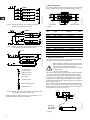
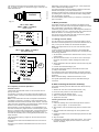
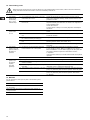
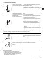
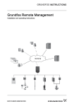
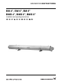
GRUNDFOS INSTRUCTIONS
BM 4", BM 6", BM 8"
BMB 4", BMB 6", BMB 8"
Installation and operating instructions
Declaration of Conformity
We, Grundfos, declare under our sole responsibility that the products
BM 4", BM 6", BM 8", BMB 4", BMB 6" and BMB 8", to which this
declaration relates, are in conformity with these Council directives on
the approximation of the laws of the EC member states:
— Machinery Directive (2006/42/EC).
Standard used: EN 809: 2009.
— Low Voltage Directive (2006/95/EC).
Standard used: EN 60204-1: 2006.
— EMC Directive (2004/108/EC).
Standards used: EN 61000-6-2: 2005 and EN 61000-6-3: 2007.
Déclaration de Conformité
Nous, Grundfos, déclarons sous notre seule responsabilité, que les
produits BM 4", BM 6", BM 8", BMB 4", BMB 6" et BMB 8", auxquels se
réfère cette déclaration, sont conformes aux Directives du Conseil
concernant le rapprochement des législations des Etats membres CE
relatives aux normes énoncées ci-dessous :
— Directive Machines (2006/42/CE).
Norme utilisée : EN 809 : 2009.
— Directive Basse Tension (2006/95/CE).
Norme utilisée : EN 60204-1: 2006.
— Directive Compatibilité Electromagnétique CEM (2004/108/CE).
Normes utilisées : EN 61000-6-2 : 2005 et EN 61000-6-3 : 2007.
Declaración de Conformidad
Nosotros, Grundfos, declaramos bajo nuestra entera responsabilidad que
los productos BM 4", BM 6", BM 8", BMB 4", BMB 6" y BMB 8", a los cuales
se refiere esta declaración, están conformes con las Directivas del
Consejo en la aproximación de las leyes de las Estados Miembros del EM:
— Directiva de Maquinaria (2006/42/CE).
Norma aplicada: EN 809: 2009.
— Directiva de Baja Tensión (2006/95/CE).
Norma aplicada: EN 60204-1: 2006.
— Directiva EMC (2004/108/CE).
Normas aplicadas: EN 61000-6-2: 2005 y EN 61000-6-3: 2007.
Δήλωση Συμμόρφωσης
Εμείς, η Grundfos, δηλώνουμε με αποκλειστικά δική μας ευθύνη ότι τα
προϊόντα BM 4", BM 6", BM 8", BMB 4", BMB 6" και BMB 8" στα οποία
αναφέρεται η παρούσα δήλωση, συμμορφώνονται με τις εξής Οδηγίες του
Συμβουλίου περί προσέγγισης των νομοθεσιών των κρατών μελών της ΕΕ:
— Οδηγία για μηχανήματα (2006/42/EC).
Πρότυπο που χρησιμοποιήθηκε: EN 809: 2009.
— Οδηγία χαμηλής τάσης (2006/95/EC).
Πρότυπο που χρησιμοποιήθηκε: EN 60204-1: 2006.
— Οδηγία Ηλεκτρομαγνητικής Συμβατότητας (EMC) (2004/108/EC).
Πρότυπα που χρησιμοποιήθηκαν: EN 61000-6-2: 2005 και
EN 61000-6-3: 2007.
Försäkran om överensstämmelse
Vi, Grundfos, försäkrar under ansvar att produkterna BM 4", BM 6", BM 8",
BMB 4", BMB 6" och BMB 8", som omfattas av denna försäkran, är i
överensstämmelse med rådets direktiv om inbördes närmande till EUmedlemsstaternas lagstiftning, avseende:
— Maskindirektivet (2006/42/EG).
Tillämpad standard: EN 809: 2009.
— Lågspänningsdirektivet (2006/95/EG).
Tillämpad standard: EN 60204-1: 2006.
— EMC-direktivet (2004/108/EG).
Tillämpade standarder: EN 61000-6-2: 2005 och EN 61000-6-3: 2007.
Overensstemmelseserklæring
Vi, Grundfos, erklærer under ansvar at produkterne BM 4", BM 6", BM 8",
BMB 4", BMB 6" og BMB 8" som denne erklæring omhandler, er i
overensstemmelse med disse af Rådets direktiver om indbyrdes
tilnærmelse til EF-medlemsstaternes lovgivning:
— Maskindirektivet (2006/42/EF).
Anvendt standard: EN 809: 2009.
— Lavspændingsdirektivet (2006/95/EF).
Anvendt standard: EN 60204-1: 2006.
— EMC-direktivet (2004/108/EF).
Anvendte standarder: EN 61000-6-2: 2005: 2005 og
EN 61000-6-3: 2007.
Konformitätserklärung
Wir, Grundfos, erklären in alleiniger Verantwortung, dass die Produkte
BM 4", BM 6", BM 8", BMB 4", BMB 6" und BMB 8", auf die sich diese
Erklärung bezieht, mit den folgenden Richtlinien des Rates zur
Angleichung der Rechtsvorschriften der EU-Mitgliedsstaaten
übereinstimmen:
— Maschinenrichtlinie (2006/42/EG).
Norm, die verwendet wurde: EN 809: 2009.
— Niederspannungsrichtlinie (2006/95/EG).
Norm, die verwendet wurde: EN 60204-1: 2006.
— EMV-Richtlinie (2004/108/EG).
Normen, die verwendet wurden: EN 61000-6-2: 2005 und
EN 61000-6-3: 2007.
Dichiarazione di Conformità
Grundfos dichiara sotto la sua esclusiva responsabilità che i prodotti
BM 4", BM 6", BM 8", BMB 4", BMB 6" e BMB 8", ai quali si riferisce questa
dichiarazione, sono conformi alle seguenti direttive del Consiglio
riguardanti il riavvicinamento delle legislazioni degli Stati membri CE:
— Direttiva Macchine (2006/42/CE).
Norma applicata: EN 809: 2009.
— Direttiva Bassa Tensione (2006/95/CE).
Norma applicata: EN 60204-1: 2006.
— Direttiva EMC (2004/108/CE).
Norme applicate: EN 61000-6-2: 2005 e EN 61000-6-3: 2007.
Declaração de Conformidade
A Grundfos declara sob sua única responsabilidade que os produtos
BM 4", BM 6", BM 8", BMB 4", BMB 6" e BMB 8", aos quais diz respeito
esta declaração, estão em conformidade com as seguintes Directivas do
Conselho sobre a aproximação das legislações dos Estados Membros da
CE:
— Directiva Máquinas (2006/42/CE).
Norma utilizada: EN 809: 2009.
— Directiva Baixa Tensão (2006/95/CE).
Norma utilizada: EN 60204-1: 2006.
— Directiva EMC (compatibilidade electromagnética) (2004/108/CE).
Normas utilizadas: EN 61000-6-2: 2005 e EN 61000-6-3: 2007.
Overeenkomstigheidsverklaring
Wij, Grundfos, verklaren geheel onder eigen verantwoordelijkheid dat de
producten BM 4", BM 6", BM 8", BMB 4", BMB 6" en BMB 8" waarop deze
verklaring betrekking heeft, in overeenstemming zijn met de Richtlijnen van
de Raad in zake de onderlinge aanpassing van de wetgeving van de EG
Lidstaten betreffende:
— Machine Richtlijn (2006/42/EC).
Gebruikte norm: EN 809: 2009.
— Laagspannings Richtlijn (2006/95/EC).
Gebruikte norm: EN 60204-1: 2006.
— EMC Richtlijn (2004/108/EC).
Gebruikte normen: EN 61000-6-2: 2005 en EN 61000-6-3: 2007.
Vaatimustenmukaisuusvakuutus
Me, Grundfos, vakuutamme omalla vastuullamme, että tuotteet BM 4",
BM 6", BM 8", BMB 4", BMB 6" ja BMB 8", joita tämä vakuutus koskee,
ovat EY:n jäsenvaltioiden lainsäädännön yhdenmukaistamiseen tähtäävien
Euroopan neuvoston direktiivien vaatimusten mukaisia seuraavasti:
— Konedirektiivi (2006/42/EY).
Sovellettu standardi: EN 809: 2009.
— Pienjännitedirektiivi (2006/95/EY).
Sovellettu standardi: EN 60204-1: 2006.
— EMC-direktiivi (2004/108/EY).
Sovellettavat standardit: EN 61000-6-2: 2005: 2005 ja
EN 61000-6-3: 2007.
Bjerringbro, 6th May 2010
Jan Strandgaard
Technical Director
Grundfos Holding A/S
Poul Due Jensens Vej 7
8850 Bjerringbro, Denmark
Person authorised to compile technical file and
empowered to sign the EC declaration of conformity.
2
BM 4", BM 6", BM 8"
BMB 4", BMB 6", BMB 8"
Installation and operating instructions
4
Montage- und Betriebsanleitung
12
Notice d'installation et d'entretien
21
Istruzioni di installazione e funzionamento
29
Instrucciones de instalación y funcionamiento
37
Instruções de instalação e funcionamento
45
Οδηγίες εγκατάστασης και λειτουργίας
53
Installatie- en bedieningsinstructies
61
Monterings- och driftsinstruktion
69
Asennus- ja käyttöohjeet
77
Monterings- og driftsinstruktion
85
3
Original installation and operating instructions.
CONTENTS
Page
Allowed
General description
Pumped liquids
Sound pressure level
4
4
4
2.
2.1
Delivery, transportation and storage
Frost protection
4
4
3.
Preparation
4
4.
4.1
Installation
Booster modules connected in series and in parallel
5
5
5.
Pipe connection
6
6.
6.1
Electrical connection
Frequency converter operation
6
7
7.
7.1
Motor protection
Setting of motor starter
7
7
Note: If the module has been stored for more than one year, the
motor liquid must be checked and refilled, if required.
8.
Before starting the booster module(s)
7
9.
9.1
Operation
Limitations to operation
8
8
Motors of standard modules are factory-filled with a Grundfos
motor liquid, SML-2, which is frost-proof down to –20°C.
10.
Automatic monitoring devices
9
Motors of modules in special version may be filled with demineralized water, i.e. not frost-proof.
9
2.1 Frost protection
11.
Checking of operation
12.
Fault finding chart
10
13.
Manuals
10
14.
Checking of motor and cable
11
15.
Disposal
11
Not allowed
TM01 1282 4197
1.
1.1
1.2
Fig. 1
If the module has to be stored, it must be stored on a frost-free
location, or it must be ensured that the motor liquid is frost-proof.
3. Preparation
Before installation, the following checks should be made:
Before beginning installation procedures, these
installation and operating instructions should be
studied carefully. The installation and operation
should also be in accordance with local regulations
and accepted codes of good practice.
1. General description
Grundfos BM and BMB booster modules are designed for pressure boosting, liquid transfer and circulation in systems with a
high static pressure.
1.1 Pumped liquids
Thin, non-explosive liquids, not containing abrasive particles or
fibres. The liquid must not attack the pump materials chemically
and mechanically.
The booster modules must not be used for the pumping of inflammable liquids such as diesel oil, petrol or
similar liquids.
1. Check for transport damages
Make sure that the module has not been damaged during
transportation.
2. Type of module
Check that the type designation given on the nameplate fitted
to the sleeve corresponds to order.
3. Electricity supply
The motor voltage and frequency are marked on the nameplate. Make sure that the motor is suitable for the electricity
supply on which it will be used.
4. Liquid in motor
If a module has been stored for more than one year, check the
motor liquid and refill, if required. Contact Grundfos.
If a module is supplied for a special system, the motor may be
supplied without liquid or with demineralized water. See section 2. Delivery, transportation and storage.
Versions:
BM 4"
Straight version
TM00 3793 4698
1.2 Sound pressure level
The sound pressure level of the booster modules BM 4", BM 6",
BMB 4" and BMB 6" is lower than 70 dB(A).
The sound pressure level of the booster modules BM 8" and
BMB 8" is lower than 80 dB(A).
TM00 3794 4698
Bent version
Delivery:
The booster modules are supplied from the factory in proper
packing in which they should remain until they are to be installed.
The modules are ready for installation.
Transportation and storage:
During transportation and storage, the booster modules may only
be placed in the positions shown in fig. 1.
Before storage, the booster modules should be flushed through
with clean freshwater, see section 9.1.2 Flushing of the booster
module.
4
BM 6"
BM 6" is only available in straight version.
TM00 4019 4698
2. Delivery, transportation and storage
BM 8"
BM 8" is only available in straight version.
BMB 4"
Not allowed
Straight version
TM01 1282 4197
TM01 1420 4698
Allowed
TM01 9711 3800
Fig. 3
L
Bent version
3/7 L
2/7 L
TM02 5911 4002 / TM00 4041 4197
TM01 9712 3800
2/7 L
BMB 6"
TM01 9713 2700
BMB 6" is only available in straight version.
Fig. 4
BMB 8"
4.1 Booster modules connected in series and
in parallel
•
For modules connected in series, mounted above each other,
it is recommended to connect the pipes as shown in fig. 5.
•
For modules connected in parallel, mounted above each other,
it is recommended to connect the pipes as shown in fig. 6.
This layout ensures that the modules are filled with water
before starting.
•
When modules are connected in series and parallel, mounted
above each other, it is recommended to connect the pipes as
shown in fig. 7.
•
For modules connected in series and fitted with a bypass,
mounted above each other, it is recommended to connect the
pipes as shown in fig. 8.
Fig. 2
4. Installation
Grundfos booster modules are supplied as standard without builtin non-return valve, but they are available with non-return valve.
For the application of a non-return valve, see fig. 6.
In systems involving the risk of water hammer in connection with
start/stop, the necessary measures must be taken to reduce this
risk.
Bypass
Bypass
The booster modules are suitable for both vertical and horizontal
installation, however, the discharge port should never fall below
the horizontal plane, see fig. 3.
4
An arrow on the module sleeve shows the direction of flow of liquid through the module, see fig. 2.
3
The module is fastened by means of clamps, see fig. 4.
2
Note that the module has an uneven weight distribution. Because of the motor, the largest weight will be
in the first third of the sleeve (when seen from the
suction port).
1
Fig. 5
TM00 3760 1902
TM01 9714 2700
BMB 8" is only available in straight version.
Booster system with four modules connected in series,
mounted above each other.
5
5. Pipe connection
The booster modules are fitted with clamp liners for Victaulic/PJE
clamp couplings on the suction and discharge sides, see fig. 9.
Bypass
Bypass
4
Bypass
Bypass
3
Bypass
Bypass
TM00 3761 1902
1
Fig. 6
Gap
Pipe system
Booster system with four modules connected in
parallel, mounted above each other.
Clamp liners
Booster module
TM01 1066 3597
2
Bypass
Bypass
Fig. 9
Bypass
Bypass
Size
Type
Victaulic
coupling
Gap
[mm]
4
3
TM00 3762 1902
Bypass
Bypass
2
1
Fig. 7
Booster system with two modules connected in series
and in parallel, mounted above each other.
Bypass
Bypass
BM 4"
BM 3A - BM 8A
1¼"
ø42 mm
1
BM 6"
BM 17 - BM 60
3"
ø89 mm
3
BM 8"
BM 30 - BM 46
3"
ø89 mm
3
BM 8"
BM 60
4"
ø114 mm
6
BM 8"
BM 77 - BM 95
5"
ø139 mm
6
BM 8"
BM 125
6"
ø168 mm
6
BMB 4"
BMB 3A - BMB 8A
1¼"
ø42 mm
1
BMB 6"
BMB 17 - BMB 60
3"
ø89 mm
3
BMB 8"
BMB 30 - BMB 46
3"
ø89 mm
3
BMB 8"
BMB 60
4"
ø114 mm
6
BMB 8"
BMB 77 - BMB 95
5"
ø139 mm
6
BMB 8"
BMB 125
6"
ø168 mm
6
4
6. Electrical connection
TM00 3763 1902
3
2
1
The electrical connection should be carried out by an authorized
electrician in accordance with local regulations.
Before making any electrical connections, make sure
that the electricity supply has been switched off and
that it cannot be accidentally switched on.
The booster modules must be connected to an external mains switch.
= Air escape
valve
Air escape
valve
= Isolating
valve valve
Closing
= Non-return
valve valve
Non return
Pressure
= Pressure
switch switch
= FlowFlow
switchswitch
It must be checked that there is voltage symmetry in the electricity supply lines, i.e. approximately same difference of voltage
between the individual phases. See also section 14. Checking of
motor and cable, point 1.
gauge
= Motor-operated
valve
Motor operated
valve
= Diaphragm tank
Diaphragm tank
Fig. 8
In order that the modules meet the EC EMC Directive (89/336/
EEC), a 0.47 µF capacitor (in accordance with IEC 384-14) must
always be connected over the two phases to which the temperature transmitter is connected, see fig. 10.
0,47 µF
Booster system with four modules connected in series
with bypass, mounted above each other.
RD
YE
BK
Note: As venting problems may arise in such installations, it is
advisable to install suitable air vent devices.
RD = Red
YE = Yellow
BK = Black
Fig. 10
6
BM/BMB
TM02 5255 2402
= Pressure
gauge
Pressure
The pump must be earthed.
The required voltage quality measured at the module terminals is
–10%/+6% of the nominal voltage during continuous operation
(including variation in the supply voltage and losses in cables).
TM02 02 5256 2402
The electrical connections must be made close to the flange
(fig. 11), either by means of a terminal box (figs. 12 and 13) or a
cable termination kit.
BM/BMB
Fig. 11
Depending on the frequency converter type, it may expose the
motor to detrimental voltage peaks.
The above disturbance can be abated by installing an RC filter
between the frequency converter and the motor.
Possible increased acoustic noise from the motor can be abated
by installing an LC filter which will also eliminate voltage peaks
from the frequency converter.
For further details, please contact your frequency converter supplier or Grundfos.
7. Motor protection
The booster module must be connected to an effective motor
starter which must protect the motor against damage from voltage
drop, phase failure, overload and a locked rotor.
BM 4", BM 6", BM 8",
BMB 4", BMB 6" and BMB 8"
Direct-on-line
L1
Red
Red :V
L2
M
Yellow
Yellow:W
BK = Black
RD = Red
YE = Yellow
L3
The control circuit must always be made in such a way that all
modules are stopped if one module fails.
TM00 4035 1694
Black :U
Black
In electricity supply systems where undervoltage and variations in
phase symmetry may occur, a phase failure relay should also be
fitted, see section 14. Checking of motor and cable.
S
U
P
P
L
Y
7.1 Setting of motor starter
For cold motors, the tripping time for the motor starter must be
less than 10 seconds (Class 10) at 5 times the rated full-load current (I1/1/ISFA) of the module, see the module nameplate.
Note: If this requirement is not met, the motor warranty will be
invalidated.
Fig. 12
In order to ensure the optimum protection of the submersible
motor, the starter overload unit should be set in accordance with
the following guidelines:
BM 6", BM 8", BMB 6" and BMB 8"
Star-delta starting
1. Set the starter overload to the rated full-load current (I1/1/ISFA)
of the module.
S
U
P
P
L
Y
W2
B2
V2
R2
2. Start the module and let it run for half an hour at normal performance, see section 8. Before starting the booster module(s).
U2
Y2
3. Slowly grade down the scale indicator until the motor trip point
is reached.
F
O
R
W1
R1
Y1
U1
B1
BK = Black
B=Black, R=Red,
RD = Red
YE = Yellow
4. Increase the overload setting by 5%.
The highest permissible setting is the rated full-load current
(I1/1/ISFA) of the module.
Y=Yellow
TM00 4034 3197
V1
M
Fig. 13
For modules wound for star-delta starting, the starter overload
unit should be set as above, but the maximum setting should be
as follows:
Starter overload setting = Rated full-load current x 0.58.
The highest permissible start-up time for star-delta starting is
2 seconds.
8. Before starting the booster module(s)
6.1 Frequency converter operation
The booster module(s) must be filled with water before start-up.
Grundfos motors:
Procedure:
Three-phase Grundfos MS motors can be connected to a frequency converter.
1. Slacken the vent valve of the booster module, if any.
If a frequency converter is to be used for booster modules connected in series, it must be connected to the last module in the
flow direction.
3. Completely open the isolating valve.
Note: If a Grundfos MS motor with a temperature transmitter is
connected to a frequency converter, a fuse incorporated in the
transmitter will melt and the transmitter will be inactive. The transmitter cannot be reactivated. This means that the motor will operate like a motor without a temperature transmitter.
2. Ensure an inlet pressure on the booster module.
4. Wait 3 to 5 minutes to ensure optimum venting.
5. Tighten the vent valve.
Checking the direction of rotation:
Procedure:
1. Close the isolating valve on the discharge side of module 1
(figs. 5 to 8) to approx. 1/3 of maximum flow.
During frequency converter operation, it is not advisable to run
the motor at a frequency higher than the nominal frequency (50 or
60 Hz). In connection with pump operation, it is important never to
reduce the frequency (and consequently the speed) to such a
level that the necessary flow of cooling liquid past the motor is no
longer ensured.
2. Start module 1 and record discharge pressure and flow readings.
The permissible frequency ranges are 30-50 Hz and 30-60 Hz,
respectively.
5. Stop the module.
During start, the maximum acceleration time from 0 to 30 Hz is
1 second.
During stop, the maximum deceleration time from 30 to 0 Hz is
1 second.
3. Stop the module and interchange two of the phases to the
module.
4. Restart the module and re-record discharge pressure and flow
readings.
6. Compare the results taken under points 2 and 4. The connection which gave the larger pressure and flow is the correct
direction of rotation.
7
The check for the direction of rotation should last for the shortest
possible time.
If the booster system has several modules, starting and rotation
checks are made in the order 1-2-3-4 until all modules are running. When module 2 is checked, module 1 must be running.
When module 3 is checked, modules 1 and 2 must be running,
etc.
9.1 Limitations to operation
The flow limits stated in the following table apply to the optimum
operating ranges of the modules as regards efficiency:
Recommended flows at 25°C (77°F)
m³/h
If modules in series are also connected in parallel (fig. 7), the
direction of rotation of each section connected in series should be
checked.
After having checked the direction of rotation, stop the modules in
the order 4-3-2-1.
The booster system is now ready for operation.
9. Operation
Start:
The booster modules are not allowed to run against a
closed discharge valve for more than 5 seconds as
this will cause an increase in temperature/formation
of steam in the module which may cause damage to
the pump and the motor.
If there is any danger of the modules running against
a closed discharge valve, a minimum liquid flow
through the module should be ensured by connecting
a bypass/a drain to the discharge side of the module.
The drain can for instance be connected to a tank.
US GPM
Type
50 Hz
60 Hz
50 Hz
60 Hz
BM 3A/BMB 3A
0.8-4.4
1.0-5.4
3.5-17.6
4.4-23.8
BM 5A/BMB 5A
2.5-6.8
3.0-8.4
11-30
13-37
BM 8A/BMB 8A
4.0-10
4.8-10
17.6-40
21-40
BM 17/BMB 17
8.0-24
8.0-29
35-106
35-128
BM 30/BMB 30
15-38
18-45
66-167
79-198
BM 46/BMB 46
24-60
28-72
106-264
123-317
BM 60/BMB 60
35-75
40-90
154-330
176-396
BM 77/BMB 77
40-100
48-120
176-440
211-528
BM 95/BMB 95
50-120
60-140
220-528
264-616
BM 125/BMB 125
70-160
80-180
308-704
352-792
The relative pressure limits stated in the following table must be
observed:
Permissible relative pressures1)
Inlet pressure
The booster modules must be started in the order 1-2-3-4 at intervals of 1 or 2 seconds, see section 4.1 Booster modules connected in series and in parallel. If other intervals are required,
contact Grundfos.
Size
Outlet pressure
Max.2)
Min.
[bar] [p.s.i.] [bar] [p.s.i.]
Module 1 is always the first module on the suction side.
During start-up, it is recommended to close the isolating valve ¾
and open it slowly (2 to 3 seconds).
In systems involving the risk of water hammer in connection with
start/stop, the necessary measures must be taken to reduce this
risk, e.g. by installing a diaphragm tank.
Max.2)
[bar]
[p.s.i.]
1160
BM 4"
0.5
7.25
60
870
80
BM 6"
0.5
7.25
50
725
80
1160
BM 8"
1
14.5
25
362
70
1015
BMB 4"
0.5
7.25
30
435
60
870
BMB 6"
0.5
7.25
20
290
50
725
BMB 8"
1
14.5
10
145
45
653
Operation:
During operation, the inlet pressure must be checked in accordance with section 9.1 Limitations to operation.
The total pressure and flow of modules connected in series
should never be changed by stopping one or more of the
modules. If different pressures or flows are required, the following
procedures are applicable:
1) Contact Grundfos if higher pressures are required.
2) Note: If the maximum inlet/outlet pressure is exceeded, install
a safety valve.
9.1.1 Cooling
The temperature and flow limits stated in the following table must
be observed to ensure sufficient cooling of the motor:
1. Bypass of module(s): Install a bypass between two modules,
see fig. 8.
Stop the module(s) which is/are not required and close the isolating valves on either side of the module.
See section 9.1.2 Flushing of the booster module.
The module(s) to be bypassed is/are always the last
module(s) in the flow direction.
Maximum permissible liquid temperature
Motor
2. Fit a reducting valve to the discharge pipe.
The values stated in section 9.1 Limitations to operation must
be observed.
3. Modules with three-phase motors: Install a frequency converter for speed control of the last booster module in the flow
direction, see section 6.1 Frequency converter operation.
Stop:
Maximum
liquid
temperature
Minimum
flow velocity
past the
motor
Minimum
flow
°C
°F
m/s (ft/s)
m³/h (US GPM)
Grundfos 4"
40
104
≥ 0.15 (0.49)
≥ 0.8 (3.5)
Grundfos 6"
40
104
≥ 0.15 (0.49)
≥ 5.5 (24)
FRANKLIN 8"
30
86
≥ 0.16 (0.52)
≥ 18.5 (81.5)
9.1.2 Flushing of the booster module
The modules must be stopped in reverse order, i.e. 4-3-2-1, at
intervals of 1 to 2 seconds, see section 4.1 Booster modules connected in series and in parallel.
When a module is flushed, the flow must be reduced to maximum
10% of the nominal flow at a minimum pressure of 2 bar. The
modules must be stopped while the system is flushed, see section 9. Operation.
If the booster system is taken out of operation for a long period,
the modules should be flushed through with clean freshwater, see
section 9.1.2 Flushing of the booster module. The modules are
then left with freshwater until they are to be used again.
Note: When pumping water with a salt concentration > 2000 ppm
NaCl, the module must be flushed through in the flow direction as
described below.
8
The flushing procedure depends on the operating condition:
•
Intermittent operation:
If the module has to be stopped for more than 30 minutes, it
must be flushed through with clean freshwater.
•
Continuous operation:
Once every 24 hours, the module should be stopped and
flushed through with raw water by means of the feed pump.
9.1.3 Frequency of starts and stops
Minimum 1 per year is recommended.
Maximum 20 per hour.
Maximum 100 per day.
Note: BM/BMB 8": Maximum 10 per day.
10. Automatic monitoring devices
To protect the modules against dry running and to ensure a minimum flow of cooling water past the motors, the system must be
fitted with flow and pressure monitoring devices (figs. 5 to 8).
A pressure switch on the suction side is dimensioned in accordance with the estimated inlet pressure. At a pressure lower than
0.5 bar for BM 4", BM 6", BMB 4" and BMB 6" and 1 bar for BM 8"
and BMB 8", an alarm is given and the module must be stopped
without delay.
All discharge connections to the system should be fitted with flow
switches which will stop the system at the set minimum flows.
The above monitoring devices ensure a correct inlet pressure and
a minimum flow of cooling water past the motor.
If the modules are stopped automatically, automatic flushing is
recommended, see section 9.1.2 Flushing of the booster module.
11. Checking of operation
Depending on the number of operating hours of the modules, the
following should be checked at suitable intervals:
•
Flow.
•
Starting frequency.
•
Control and protective devices.
•
Liquid temperature.
•
Minimum flow through modules during operation.
If any of the above checks reveal any abnormal operating details,
inspection should be carried out in accordance with the fault
finding chart.
It is recommended to use the log book at the end of these instructions.
9
12. Fault finding chart
Before removing the terminal box cover and before any removal/dismantling of the module, make sure that the electricity
supply has been switched off and that it cannot be accidentally switched on.
Fault
Cause
Remedy
1. The booster
system stops
occasionally.
One or more
modules stop.
a) No or insufficient water supply. The pressure switch has cut out.
Check that the pressure switch functions normally (without
delay) and is adjusted correctly. Check that the minimum inlet
pressure is correct.
b) The capacity is too small. The flow switch
has cut out.
The discharge pipe is totally or partly blocked due to incorrectly
adjusted manually operated valve, or failure in the magnetic or
motor-operated valve.
Check these valves.
The flow switch is faulty or incorrectly adjusted. Check/adjust
the switch.
a) The fuses are blown.
Check and replace both main fuses and/or fuses for control
circuit.
b) The motor starter overload unit has tripped
out.
Reset the starter overload. If it trips out again, the voltage
should be checked.
c) The magnetic coil of motor starter/contactor is short-circuited (not cutting in).
Replace the coil. Check the coil voltage.
d) The control circuit has cut out or is defective.
Check the control circuit and the contacts in the monitoring
devices (pressure switch, flow switch, etc.).
e) The motor/supply cable is defective.
Check motor and cable. See also section 14. Checking of motor
and cable.
a) No water or too small quantity delivered
to the modules or air in the system.
Check that the inlet pressure during operation is at least
0.5 bar for BM 4", BM 6", BMB 4" and BMB 6" and 1 bar for
BM 8" and BMB 8". If so, the water supply is OK. Stop and vent
the system. Restart the system as described in section
9. Operation.
2. The booster
system does
not run.
3. The booster
system runs, but
gives no water or
develops no
pressure.
If the module is defective, it should be dismantled and repaired/
replaced.
4. The booster
system runs
at reduced
capacity
(flow and
pressure).
b) Suction parts are blocked.
Pull the pump out of the sleeve and clean the suction parts.
a) Wrong direction of rotation.
See section 8. Before starting the booster module(s).
b) The valves on the discharge side are partly
closed or blocked.
Check valves.
c) The discharge pipe is partly blocked by
impurities.
Measure the discharge pressure and compare with the calculated data. Clean or replace the discharge pipe.
d) The module is partly blocked by impurities. Pull the pump out of the sleeve. Dismantle, clean and check the
pump. Any defective parts should be replaced. Clean the pipes.
e) The module is defective.
13. Manuals
For the replacement and repair of parts of the booster system,
please refer to:
Related documentation
Service Manual for Replacement of Motor Cable and Motor
(4", 6" and 8").
Parts Lists with instructions for dismantling and assembly of
pump and motor.
www.grundfos.com/xxx
10
Pull the pump out of the sleeve. Dismantle, clean and check the
pump. Any defective parts should be replaced. See section
13. Manuals.
14. Checking of motor and cable
1. Supply voltage
Measure the voltage between the
phases by means of a voltmeter.
TM00 1371 5092
Connect the voltmeter to the terminals
in the motor starter.
The voltage should, when the motor is loaded, be within
–10%/+6% of the rated voltage. The motor may burn if there
are larger variations in voltage.
If the voltage is constantly too high or too low, the motor must
be replaced by one corresponding to the supply voltage.
Large variations in voltage indicate poor electricity supply, and
the module should be stopped until the defect has been found.
Resetting of the motor starter may be necessary.
Voltmeter
2. Current consumption
Measure the current of each phase
while the module is operating at a
constant discharge pressure (if possible at the capacity where the motor is
most heavily loaded).
For normal operating current, see
nameplate.
Calculate the current unbalance (%) in the three phases as
follows:
1. Add up the three phase currents.
2. Divide this value by three to ascertain the average current.
3. Find the phase current differing most from the average
current.
4. Compare the results from points 2 and 3.
5. Divide the difference by the average value and multiply by
100. The result is the current unbalance in %.
TM00 1372 5092
For three-phase motors, the current unbalance must not
exceed 5%. If so, or if the current exceeds the maximum operating current, there are the following possible faults:
• The contacts of the motor starter are burnt. Replace the
contacts.
• Poor connection in leads, possibly in terminal box.
Ammeter
• Too high or too low supply voltage, see point 1.
• The motor windings are short-circuited or partly disjointed,
see point 3.
• Damaged pump is causing the motor to be overloaded. Pull
the pump out of the sleeve for overhaul.
• The resistance value of the motor windings deviates too
much. Move the phases in phase order to a more uniform
load. If this does not help, see point 3.
Items 3 and 4: Measurement not needed if supply voltage and current consumption are normal.
3. Winding resistance
Remove the phase leads from the terminal box.
TM00 1373 5092
Measure the winding resistance as
shown on the drawing.
The highest value must not exceed the lowest value by more
than 10%.
If the deviation is higher, the pump should be pulled out. Measure motor and cable separately and replace or repair defective
parts.
See section 13. Manuals.
Ohmmeter
TM00 1374 5092
4. Insulation resistance
Remove the phase leads from the terminal box.
Measure the insulation resistance from
each phase to earth (frame). (Make
sure that the earth connection is made
carefully.)
If the measured insulation resistance is less than 0.5 megohms and the supply cable is OK, the pump should be pulled
out for motor or cable repair or replacement.
See section 13. Manuals.
Megohmmeter
15. Disposal
Disposal of this product or parts of it must be carried out according to the following guidelines:
1. Use the local public or private waste collection service.
2. In case such waste collection service does not exist or cannot
handle the materials used in the product, please deliver the
product or any hazardous materials form it to your nearest
Grundfos company or service workshop.
Subject to alterations.
11
LOG BOOK for BM/BMB booster modules
Product No:
Installation date:
Company/your ref.
Country:
Type:
Start of operation:
City:
VFD/Softstart.
Date
Amb.
temp.
Liquid
temp.
Flow/
pressure
Current
[A]
Voltage
[V]
Brand
Comments
93
System sketch
94
Argentina
Bombas GRUNDFOS de Argentina
S.A.
Ruta Panamericana km. 37.500 Lote
34A
1619 - Garin
Pcia. de Buenos Aires
Phone: +54-3327 414 444
Telefax: +54-3327 411 111
Australia
GRUNDFOS Pumps Pty. Ltd.
P.O. Box 2040
Regency Park
South Australia 5942
Phone: +61-8-8461-4611
Telefax: +61-8-8340 0155
Austria
GRUNDFOS Pumpen Vertrieb
Ges.m.b.H.
Grundfosstraße 2
A-5082 Grödig/Salzburg
Tel.: +43-6246-883-0
Telefax: +43-6246-883-30
Belgium
N.V. GRUNDFOS Bellux S.A.
Boomsesteenweg 81-83
B-2630 Aartselaar
Tél.: +32-3-870 7300
Télécopie: +32-3-870 7301
Belorussia
Представительство ГРУНДФОС в
Минске
220123, Минск,
ул. В. Хоружей, 22, оф. 1105
Тел.: +(37517) 233 97 65,
Факс: +(37517) 233 97 69
E-mail: [email protected]
Bosnia/Herzegovina
GRUNDFOS Sarajevo
Trg Heroja 16,
BiH-71000 Sarajevo
Phone: +387 33 713 290
Telefax: +387 33 659 079
e-mail: [email protected]
Brazil
BOMBAS GRUNDFOS DO BRASIL
Av. Humberto de Alencar Castelo
Branco, 630
CEP 09850 - 300
São Bernardo do Campo - SP
Phone: +55-11 4393 5533
Telefax: +55-11 4343 5015
Bulgaria
GRUNDFOS Pumpen Vertrieb
Representative Office - Bulgaria
Bulgaria, 1421 Sofia
Lozenetz District
105-107 Arsenalski blvd.
Phone: +359 2963 3820, 2963 5653
Telefax: +359 2963 1305
Canada
GRUNDFOS Canada Inc.
2941 Brighton Road
Oakville, Ontario
L6H 6C9
Phone: +1-905 829 9533
Telefax: +1-905 829 9512
China
GRUNDFOS Pumps (Shanghai) Co.
Ltd.
51 Floor, Raffles City
No. 268 Xi Zang Road. (M)
Shanghai 200001
PRC
Phone: +86-021-612 252 22
Telefax: +86-021-612 253 33
Croatia
GRUNDFOS CROATIA d.o.o.
Cebini 37, Buzin
HR-10010 Zagreb
Phone: +385 1 6595 400
Telefax: +385 1 6595 499
www.grundfos.hr
Czech Republic
GRUNDFOS s.r.o.
Čajkovského 21
779 00 Olomouc
Phone: +420-585-716 111
Telefax: +420-585-716 299
Denmark
GRUNDFOS DK A/S
Martin Bachs Vej 3
DK-8850 Bjerringbro
Tlf.: +45-87 50 50 50
Telefax: +45-87 50 51 51
E-mail: [email protected]
www.grundfos.com/DK
Estonia
GRUNDFOS Pumps Eesti OÜ
Peterburi tee 92G
11415 Tallinn
Tel: + 372 606 1690
Fax: + 372 606 1691
Finland
OY GRUNDFOS Pumput AB
Mestarintie 11
FIN-01730 Vantaa
Phone: +358-3066 5650
Telefax: +358-3066 56550
France
Pompes GRUNDFOS Distribution S.A.
Parc d’Activités de Chesnes
57, rue de Malacombe
F-38290 St. Quentin Fallavier (Lyon)
Tél.: +33-4 74 82 15 15
Télécopie: +33-4 74 94 10 51
Germany
GRUNDFOS GMBH
Schlüterstr. 33
40699 Erkrath
Tel.: +49-(0) 211 929 69-0
Telefax: +49-(0) 211 929 69-3799
e-mail: [email protected]
Service in Deutschland:
e-mail: [email protected]
Greece
GRUNDFOS Hellas A.E.B.E.
20th km. Athinon-Markopoulou Av.
P.O. Box 71
GR-19002 Peania
Phone: +0030-210-66 83 400
Telefax: +0030-210-66 46 273
Hong Kong
GRUNDFOS Pumps (Hong Kong) Ltd.
Unit 1, Ground floor
Siu Wai Industrial Centre
29-33 Wing Hong Street &
68 King Lam Street, Cheung Sha Wan
Kowloon
Phone: +852-27861706 / 27861741
Telefax: +852-27858664
Hungary
GRUNDFOS Hungária Kft.
Park u. 8
H-2045 Törökbálint,
Phone: +36-23 511 110
Telefax: +36-23 511 111
India
GRUNDFOS Pumps India Private Limited
118 Old Mahabalipuram Road
Thoraipakkam
Chennai 600 096
Phone: +91-44 2496 6800
Indonesia
PT GRUNDFOS Pompa
Jl. Rawa Sumur III, Blok III / CC-1
Kawasan Industri, Pulogadung
Jakarta 13930
Phone: +62-21-460 6909
Telefax: +62-21-460 6910 / 460 6901
Ireland
GRUNDFOS (Ireland) Ltd.
Unit A, Merrywell Business Park
Ballymount Road Lower
Dublin 12
Phone: +353-1-4089 800
Telefax: +353-1-4089 830
Italy
GRUNDFOS Pompe Italia S.r.l.
Via Gran Sasso 4
I-20060 Truccazzano (Milano)
Tel.: +39-02-95838112
Telefax: +39-02-95309290 / 95838461
Japan
GRUNDFOS Pumps K.K.
Gotanda Metalion Bldg., 5F,
5-21-15, Higashi-gotanda
Shiagawa-ku, Tokyo
141-0022 Japan
Phone: +81 35 448 1391
Telefax: +81 35 448 9619
Korea
GRUNDFOS Pumps Korea Ltd.
6th Floor, Aju Building 679-5
Yeoksam-dong, Kangnam-ku, 135-916
Seoul, Korea
Phone: +82-2-5317 600
Telefax: +82-2-5633 725
Latvia
SIA GRUNDFOS Pumps Latvia
Deglava biznesa centrs
Augusta Deglava ielā 60, LV-1035,
Rīga,
Tālr.: + 371 714 9640, 7 149 641
Fakss: + 371 914 9646
Slovenia
GRUNDFOS d.o.o.
Šlandrova 8b, SI-1231 LjubljanaČrnuče
Phone: +386 1 568 0610
Telefax: +386 1 568 0619
E-mail: [email protected]
Lithuania
GRUNDFOS Pumps UAB
Smolensko g. 6
LT-03201 Vilnius
Tel: + 370 52 395 430
Fax: + 370 52 395 431
Spain
Bombas GRUNDFOS España S.A.
Camino de la Fuentecilla, s/n
E-28110 Algete (Madrid)
Tel.: +34-91-848 8800
Telefax: +34-91-628 0465
Malaysia
GRUNDFOS Pumps Sdn. Bhd.
7 Jalan Peguam U1/25
Glenmarie Industrial Park
40150 Shah Alam
Selangor
Phone: +60-3-5569 2922
Telefax: +60-3-5569 2866
Sweden
GRUNDFOS AB
Box 333 (Lunnagårdsgatan 6)
431 24 Mölndal
Tel.: +46(0)771-32 23 00
Telefax: +46(0)31-331 94 60
México
Bombas GRUNDFOS de México S.A.
de C.V.
Boulevard TLC No. 15
Parque Industrial Stiva Aeropuerto
Apodaca, N.L. 66600
Phone: +52-81-8144 4000
Telefax: +52-81-8144 4010
Netherlands
GRUNDFOS Netherlands
Veluwezoom 35
1326 AE Almere
Postbus 22015
1302 CA ALMERE
Tel.: +31-88-478 6336
Telefax: +31-88-478 6332
e-mail: [email protected]
New Zealand
GRUNDFOS Pumps NZ Ltd.
17 Beatrice Tinsley Crescent
North Harbour Industrial Estate
Albany, Auckland
Phone: +64-9-415 3240
Telefax: +64-9-415 3250
Norway
GRUNDFOS Pumper A/S
Strømsveien 344
Postboks 235, Leirdal
N-1011 Oslo
Tlf.: +47-22 90 47 00
Telefax: +47-22 32 21 50
Poland
GRUNDFOS Pompy Sp. z o.o.
ul. Klonowa 23
Baranowo k. Poznania
PL-62-081 Przeźmierowo
Tel: (+48-61) 650 13 00
Fax: (+48-61) 650 13 50
Portugal
Bombas GRUNDFOS Portugal, S.A.
Rua Calvet de Magalhães, 241
Apartado 1079
P-2770-153 Paço de Arcos
Tel.: +351-21-440 76 00
Telefax: +351-21-440 76 90
România
GRUNDFOS Pompe România SRL
Bd. Biruintei, nr 103
Pantelimon county Ilfov
Phone: +40 21 200 4100
Telefax: +40 21 200 4101
E-mail: [email protected]
Russia
ООО Грундфос
Россия, 109544 Москва, ул.
Школьная 39
Тел. (+7) 495 737 30 00, 564 88 00
Факс (+7) 495 737 75 36, 564 88 11
E-mail
[email protected]
Switzerland
GRUNDFOS Pumpen AG
Bruggacherstrasse 10
CH-8117 Fällanden/ZH
Tel.: +41-1-806 8111
Telefax: +41-1-806 8115
Taiwan
GRUNDFOS Pumps (Taiwan) Ltd.
7 Floor, 219 Min-Chuan Road
Taichung, Taiwan, R.O.C.
Phone: +886-4-2305 0868
Telefax: +886-4-2305 0878
Thailand
GRUNDFOS (Thailand) Ltd.
92 Chaloem Phrakiat Rama 9 Road,
Dokmai, Pravej, Bangkok 10250
Phone: +66-2-725 8999
Telefax: +66-2-725 8998
Turkey
GRUNDFOS POMPA San. ve Tic. Ltd.
Sti.
Gebze Organize Sanayi Bölgesi
Ihsan dede Caddesi,
2. yol 200. Sokak No. 204
41490 Gebze/ Kocaeli
Phone: +90 - 262-679 7979
Telefax: +90 - 262-679 7905
E-mail: [email protected]
Ukraine
ТОВ ГРУНДФОС УКРАЇНА
01010 Київ, Вул. Московська 8б,
Тел.:(+38 044) 390 40 50
Фах.: (+38 044) 390 40 59
E-mail: [email protected]
United Arab Emirates
GRUNDFOS Gulf Distribution
P.O. Box 16768
Jebel Ali Free Zone
Dubai
Phone: +971-4- 8815 166
Telefax: +971-4-8815 136
United Kingdom
GRUNDFOS Pumps Ltd.
Grovebury Road
Leighton Buzzard/Beds. LU7 8TL
Phone: +44-1525-850000
Telefax: +44-1525-850011
U.S.A.
GRUNDFOS Pumps Corporation
17100 West 118th Terrace
Olathe, Kansas 66061
Phone: +1-913-227-3400
Telefax: +1-913-227-3500
Usbekistan
Представительство ГРУНДФОС в
Ташкенте
700000 Ташкент ул.Усмана Носира
1-й
тупик 5
Телефон: (3712) 55-68-15
Факс: (3712) 53-36-35
Serbia
GRUNDFOS Predstavništvo Beograd
Dr. Milutina Ivkovića 2a/29
YU-11000 Beograd
Phone: +381 11 26 47 877 / 11 26 47
496
Telefax: +381 11 26 48 340
Singapore
GRUNDFOS (Singapore) Pte. Ltd.
24 Tuas West Road
Jurong Town
Singapore 638381
Phone: +65-6865 1222
Telefax: +65-6861 8402
Addresses revised 24.03.2010
Being responsible is our foundation
Thinking ahead makes it possible
Innovation is the essence
150095 0510
Repl. 150095 0804
www.grundfos.com
30
The name Grundfos, the Grundfos logo, and the payoff Be–Think–Innovate are registrated trademarks
owned by Grundfos Management A/S or Grundfos A/S, Denmark. All rights reserved worldwide.