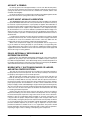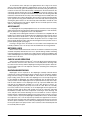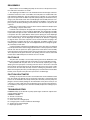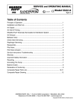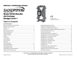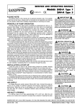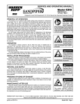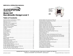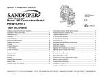
1
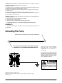
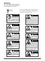
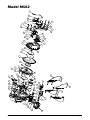
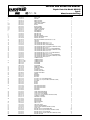
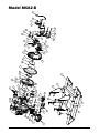
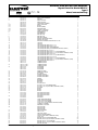
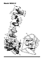
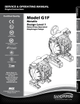
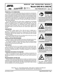
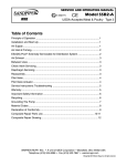
SERVICE AND OPERATING MANUAL
Models MSA2 MSA2-B MSA2-C
I M2 c T5
II 2GD T5
CE
Type 5
Mine/Construction-Duty
Table of Contents
Principle of Operation ............................................................................................ 1
Installation and Start-Up ........................................................................................ 1
Air Supply .............................................................................................................. 1
Air Inlet & Priming .................................................................................................. 2
Air Valve Lubrication .............................................................................................. 2
ESADS+Plus®: Externally Serviceable Air Distribution System ................................ 2
Air Exhaust ............................................................................................................ 3
Between Uses ....................................................................................................... 3
Check Valve Servicing ........................................................................................... 3
Diaphragm Servicing ............................................................................................. 3
Reassembly ........................................................................................................... 4
Pilot Valve .............................................................................................................. 4
Pilot Valve Actuator ................................................................................................ 4
Service Instructions: Troubleshooting ................................................................4-5
Grounding The Pump ............................................................................................ 5
Recycling ............................................................................................................... 6
Important Safety Information ................................................................................. 6
Material Codes ...................................................................................................... 7
Composite Repair Parts List MSA2 ....................................................................... 8
Composite Repair Drawing MSA2 ......................................................................... 9
Composite Repair Parts List MSA2-B ................................................................. 10
Composite Repair Drawing MSA2-B ................................................................... 11
Composite Repair Parts List MSA2-C ................................................................. 12
Composite Repair Drawing MSA2-C ................................................................... 13
Warren Rupp, Inc A Unit of IDEX Corporation • P.O. Box 1568, Mansfield, Ohio 44901-1568 USA
Telephone (419) 524-8388 • Fax (419) 522-7867 • www.warrenrupp.com
Models MSA2 MSA2-B MSA2-C
©Copyright 2009 Warren Rupp, Inc. All rights reserved.
SERVICE AND OPERATING MANUAL
Models MSA2 MSA2-B MSA2-C
I M2 c T5
II 2GD T5
CE
Type 5
Mine/Construction-Duty
PRINCIPLE OF PUMP OPERATION
This flap swing check valve pump is powered by compressed air and is a 1:1
pressure ratio design. It alternately pressurizes the inner side of one diaphragm
chamber, while simultaneously exhausting the other inner chamber. This causes the
diaphragms, which are connected by a common rod, to move endwise. Air pressure
is applied over the entire surface of the diaphragm, while liquid is discharged from
the opposite side. The diaphragm operates under a balanced condition during the
discharge stroke, which allows the unit to be operated at discharge heads over 200
feet (61 meters) of water head.
Since the diaphragms are connected by a common rod, secured by plates to the
center of the diaphragms, one diaphragm performs the discharge stroke, while the
other is pulled to perform the suction stroke in the opposite chamber.
For maximum diaphragm life, keep the pump as close to the liquid being pumped
as possible. Positive suction head in excess of 10 feet of liquid (3.048 meters) may
require a back pressure regulating device. This will maximize diaphragm life.
Alternate pressuring and exhausting of the diaphragm chamber is performed by
means of an externally mounted, pilot operated, four-way spool type air distribution
valve. When the spool shifts to one end of the valve body, inlet air pressure is applied
to one diaphragm chamber and the other diaphragm chamber exhausts. When the
spool shifts to the opposite end of the valve body, the porting of chambers is reversed.
The air distribution valve spool is moved by an internal pilot valve which alternately
pressurizes one side of the air distribution valve spool, while exhausting the other
side. The pilot valve is shifted at each end of the diaphragm stroke by the diaphragm
plate coming in contact with the end of the pilot spool. This pushes it into position for
shifting of the air distribution valve.
The chambers are manifolded together with a suction and discharge flap-type
check valve for each chamber, maintaining flow in one direction through the pump.
INSTALLATION & START-UP
Locate the pump as close to the product being pumped as possible, keeping
suction line length and number of fittings to a minimum. Do not reduce line size.
For installations of rigid piping, short flexible sections of hose should be installed
between pump and piping. This reduces vibration and strain to the piping system.
A Warren Rupp Tranquilizer® surge suppressor is recommended to further reduce
pulsation in flow.
This pump was tested at the factory prior to shipment and is ready for operation.
It is completely self-priming from a dry start for suction lifts of 20 feet (6.096 meters)
or less. For suction lifts exceeding 20 feet of liquid, fill the chambers with liquid prior
to priming.
AIR SUPPLY
Air supply pressures cannot exceed 125 psi (8.61 bar). Connect the pump air inlet
to an air supply of sufficient capacity and pressure required for desired performance.
When the air line is solid piping, use a short length of flexible hose [not less than
3/4" (19mm) in diameter] between pump and piping to eliminate strain to pipes.
msa2dl5sm-REV0309
Models MSA2 MSA2-B MSA2-C
Page 1
AIR INLET & PRIMING
For start-up, open an air valve approximately 1/2" to 3/4" turn. After the unit primes,
an air valve can be opened to increase flow as desired. If opening the valve increases
cycling rate, but does not increase flow rate, cavitation has occurred, and the valve
should be closed slightly.
For the most efficient use of compressed air and the longest diaphragm life, throttle
the air inlet to the lowest cycling rate that does not reduce flow.
A NOTE ABOUT AIR VALVE LUBRICATION
The SANDPIPER pump’s pilot valve and main air valve assemblies are designed
to operate WITHOUT lubrication. This is the preferred mode of operation. There may
be instances of personal preference, or poor quality air supplies when lubrication of
the compressed air supply is required. The pump air system will operate with properly
lubricated compressed air supplies. Proper lubrication of the compressed air supply would entail the use of an air line lubricator (available from Warren Rupp) set to
deliver one drop of 10 wt., non-detergent oil for every 20 SCFM of air the pump consumed at its point of operation. Consult the pump’s published Performance Curve to
determine this.
It is important to remember to inspect the sleeve and spool set routinely. It should
move back and forth freely. This is most important when the air supply is lubricated.
If a lubricator is used, oil accumulation will, over time, collect any debris from the
compressed air. This can prevent the pump from operating properly.
Water in the compressed air supply can create problems such as icing or freezing of the exhaust air causing the pump to cycle erratically, or stop operating. This
can be addressed by using a point of use air dryer to supplement a plant’s air drying
equipment. This device will remove excess water from the compressed air supply and
alleviate the icing or freezing problem.
ESADS: EXTERNALLY SERVICEABLE AIR
DISTRIBUTION SYSTEM
Please refer to the exploded view drawing and parts list in the Service Manual
supplied with your pump. If you need replacement or additional copies, contact your
local Warren Rupp Distributor, or the Warren Rupp factory Literature Department at
the number shown below. To receive the correct manual, you must specify the MODEL
and TYPE information found on the name plate of the pump.
MODELS WITH 1" SUCTION/DISCHARGE OR LARGER,
AND METAL CENTER SECTIONS:
The main air valve sleeve and spool set is located in the valve body mounted on
the pump with four hex head capscrews. The valve body assembly is removed from
the pump by removing these four hex head capscrews.
With the valve body assembly off the pump, access to the sleeve and spool set
is made by removing four hex head capscrews (each end) on the end caps of the
valve body assembly. With the end caps removed, slide the spool back and forth in
the sleeve. The spool is closely sized to the sleeve and must move freely to allow for
proper pump operation. An accumulation of oil, dirt or other contaminants from the
pump’s air supply, or from a failed diaphragm, may prevent the spool from moving freely.
This can cause the spool to stick in a position that prevents the pump from operating.
If this is the case, the sleeve and spool set should be removed from the valve body
for cleaning and further inspection.
Remove the spool from the sleeve. Using an arbor press or bench vise (with an
improvised mandrel), press the sleeve from the valve body. Take care not to damage
the sleeve. At this point, inspect the o-rings on the sleeve for nicks, tears or abrasions.
Damage of this sort could happen during assembly or servicing. A sheared or cut
o-ring can allow the pump’s compressed air supply to leak or bypass within the air
valve assembly, causing the pump to leak compressed air from the pump air exhaust
or not cycle properly. This is most noticeable at pump dead head or high discharge
pressure conditions. Replace any of these o-rings as required or set up a routine,
preventive maintenance schedule to do so on a regular basis. This practice should
include cleaning the spool and sleeve components with a safety solvent or equivalent,
inspecting for signs of wear or damage, and replacing worn components.
Models MSA2 MSA2-B MSA2-C
Page 2
msa2dl5sm-REV0309
To re-install the sleeve and spool set, lightly lubricate the o-rings on the sleeve
with an o-ring assembly lubricant or lightweight oil (such as 10 wt. air line lubricant).
Re-install one end cap, gasket and bumper on the valve body. Using the arbor press
or bench vise that was used in disassembly, carefully press the sleeve back into the
valve body, without shearing the o-rings. You may have to clean the surfaces of the
valve body where the end caps mount. Material may remain from the old gasket. Old
material not cleaned from this area may cause air leakage after reassembly. Take care
that the bumper stays in place allowing the sleeve to press in all the way. Reinstall the
spool, opposite end cap, gasket and bumper on the valve body. After inspecting and
cleaning the gasket surfaces on the valve body and intermediate, reinstall the valve
body on the pump using new gaskets. Tighten the four hex head capscrews evenly
and in an alternating cross pattern.
AIR EXHAUST
If a diaphragm fails, the pumped liquid or fumes can enter the air end of the pump,
and be exhausted into the atmosphere. When pumping hazardous or toxic materials,
pipe the exhaust to an appropriate area for safe disposition.
This pump can be submerged if materials of construction are compatible with the
liquid. The air exhaust must be piped above the liquid level. Piping used for the air
exhaust must not be smaller than 1" (2.54 cm). Reducing the pipe size will restrict
air flow and reduce pump performance .When the product source is at a higher level
than the pump (flooded suction), pipe the exhaust higher than the product source to
prevent siphoning spills. (See page 7)
Freezing or icing-up of the air exhaust can occur under certain temperature and
humidity conditions. Use of an air dryer unit should eliminate most icing problems.
BETWEEN USES
When used for materials that tend to settle out or transform to solid form, the pump
should be completely flushed after each use, to prevent damage. Product remaining
in the pump between uses could dry out or settle out. This could cause problems with
valves and diaphragms at re-start. In freezing temperatures, the pump must be drained
between uses in all cases.
CHECK VALVE SERVICING
Valve inspection requires removal of (4) 3/8" hex nuts. On the suction side the flange,
when removed, carries the valve and seat as an assembly. On the discharge side,
the valve and seat will stay with the diaphragm housing. Visual inspection and cleaning is possible. If parts are to be replaced, remove the self locking nuts and all parts
are accessible.
DIAPHRAGM SERVICING
Diaphragms can be inspected or the diaphragm assembly removed without
removing the suction and discharge flanges. Remove (8) nuts around the chamber
flange, and the housing assembly will pull off. Check valves can be inspected for
proper seating at this point as well as the diaphragm. Use care to keep foreign matter from behind the diaphragm. The opposite diaphragm may be inspected by the
same procedure. If either diaphragm has to be replaced, follow closely these steps:
Pull the outer diameter of one diaphragm off the (8) capscrews. NOTE: One side
only! On the free diaphragm assembly, use a 3/8" allen wrench to turn the assembly (diaphragm, plates and screw) loose from the shaft. Once the assembly
has turned, it will turn out by hand by use of the diaphragm. Now the opposite diaphragm assembly and the drive shaft will pull free from the capscrews and pump
intermediate assembly. The interior components consisting of sleeve bearings, rod
seals, and pilot valve actuator bushings are now accessible for service if required.
Hold the shaft in a clamping device making sure to protect surface of shaft so as not to
scratch or mar it in any way. The diaphragm assembly will turn loose. To disassemble
the components, turn a 1/4"-20 capscrew by hand into the tapped hole in the inner
plate. This keeps the plate from turning while the socket head capscrew is removed.
To do this, place assembly in a vise so the two protruding ends of screws are loose in
the vise jaws (about 3/4" apart). Turn the center screw loose from the back plate and
the assembly will come apart.
msa2dl5sm-REV0309
Models MSA2 MSA2-B MSA2-C
Page 3
REASSEMBLY
All procedures for reassembling the pump are the reverse of the previous instructions with further instructions as shown:
1. The diaphragm assemblies are to be installed with the natural bulge outward or
toward the head of the center screw. Make sure both plates are installed with outer
radii against the diaphragm. After all components are in position in a vise and hand
tight, set a torque wrench for 480 inch pounds (40 ft. pounds) (54.23 Newton meters)
using a (3/8") allen head socket. After each diaphragm sub assembly has been completed, thread one assembly into the shaft (held near the middle in a vise having soft
jaws to protect the finish) making sure the stainless steel washer is in place on the
capscrew.
Make sure 1/4"-20 mounting screw has been removed and that the bumper (Item
#19 on drawing) is in place in the shaft.
Install this sub assembly into the pump and secure by placing the outer chamber
housing and capscrews on the end with the diaphragm. This will hold the assembly
in place while the opposite side is installed. Make sure the last diaphragm assembly
is torqued to 30 ft. lbs. (40.67 Newton meters) before placing the outer diaphragm
over the capscrews. If the holes in the diaphragm flange do not line up with the holes
in the chamber flange, turn the diaphragm assembly in the direction of tightening
to align the holes so that the capscrews can be inserted. This final torquing of the
last diaphragm assembly will lock the two diaphragm assemblies together. Place
remaining outer chamber on the open end and tighten down the securing nuts gradually and evenly on both sides.
Caution should be used while reassembling check valves. The valves are designed
for some preload over the retainer hinge pad. This is done to insure proper face contact
with the seat. After all parts are in place, tighten the lock nuts down on the assembly
to the point where visual inspection shows that seat and valve face mate without gap.
This is important for dry prime. However, after priming action has started, valves will
function due to differential pressure without concern or trouble.
PILOT VALVE
The pilot valve assembly is accessed by removing the main air distribution valve
body from the pump and lifting the pilot valve body out of the intermediate housing.
Most problems with the pilot valve can be corrected by replacing the o-rings.
Always grease the spool prior to inserting it into the sleeve. If the sleeve is removed
from the body, reinsertion must be at the chamfered side. Grease the o-rings to slide
the sleeve into the valve body. Securely insert the retaining ring around the sleeve.
When reinserting the pilot valve, push both plungers (located inside the intermediate
bracket) out of the path of the pilot valve spool ends to avoid damage.
PILOT VALVE ACTUATOR
Bushings for the pilot valve actuators are threaded into the intermediate bracket
from the outside. The plunger may be removed for inspection or replacement. First
remove the air distribution valve body and the pilot valve body from the pump. The
plungers can be located by looking into the intermediate. It may be necessary to use
a fine piece of wire to pull them out. The bushing can be turned out through the inner chamber by removing the outer chamber assembly. Replace the bushings if pins
have bent.
TROUBLESHOOTING
PROBLEM: Pump cycles but will not pump. (Note: higher suction lifts require faster
cycling speed for priming.)
POSSIBLE CAUSES:
A. Air leak in suction line.
B. Excessive suction lift.
C. Check valve not seating properly.
D. Leakage at joint of suction manifold or elbow flange.
E. Suction line or strainer plugged.
F. Diaphragm ruptured.
Models MSA2 MSA2-B MSA2-C
Page 4
msa2dl5sm-REV0309
PROBLEM: Pump will not cycle. (Note: Always disconnect air supply to relieve air
pressure before disassembling any portion of pump.)
POSSIBLE CAUSES:
A. Discharge hose or line plugged, or discharge head requirement greater than air
supply pressure. (Disconnect discharge line to check.)
B. Spool in air distribution valve not shifting. (Remove end cap and check spool —
must slide freely.)
C. Diaphragm ruptured. (Air will escape out discharge line in this case.)
D. Blockage in diaphragm chamber preventing movement. (Shut off air supply and
reopen after pressure is relieved.)
PROBLEM: Uneven discharge flow. (Indicates one chamber not operating properly.)
POSSIBLE CAUSES:
A. Check valve not sealing properly in one chamber.
B. Diaphragm failure in one chamber.
C. Air leak at suction manifold joint or elbow flange one side.
For additional information, see the Warren Rupp Troubleshooting Guide.
WARRANTY:
This unit is guaranteed for a period of five years against defective material and
workmanship.
Grounding The Pump
ONE EYELET IS FASTENED TO THE PUMP HARDWARE.
ONE EYELET IS INSTALLED TO A TRUE EARTH GROUND.
(REQUIRES A 5/16 OR 8MM MAXIMUM DIAMETER BOLT)
This 8 foot long (244 centimeters)
G r o u n d S t ra p, p a r t nu m b e r
920-025-000, can be ordered as a
service item.
To reduce the risk of static electrical
sparking, this pump must be grounded.
Check the local electrical code for
detailed grounding instruction and the
type of equipment required.
WARNING
Take action to prevent static
sparking. Fire or explosion
can result, especially when
handling flammable liquids. The pump,
piping, valves, containers or other
m i s c e l l a n e o u s e q u i p m e n t mu s t b e
grounded.
©2009 Warren Rupp, Inc. All rights reserved.
®Warren Rupp, SANDPIPER and Tranquilizer are registered tradenames of Warren Rupp, Inc.
Printed in U.S.A.
msa2dl5sm-REV0309
Models MSA2 MSA2-B MSA2-C
Page 5
Recycling
Many components of SANDPIPER® Metallic AODD pumps are
made of recyclable materials. We encourage pump users to
recycle worn out parts and pumps whenever possible, after any
hazardous pumped fluids are thoroughly flushed.
Pump complies with EN809 Pumping Directive and Directive 98/37/EC
I M2 c T5
II 2GD T5
Safety of Machinery, and ATEX 100a Directive 94/9/EC Equipment for
use in Potentially Explosive Environments. For documentation consult
CE
the manufacturer or visit: www.warrenrupp.com
IMPORTANT
Read these safety warnings
and instructions in this
manual completely, before
installation and start-up
of the pump. It is the
responsibility of the purchaser to retain this
manual for reference. Failure to comply with
the recommendations stated in this manual will
damage the pump, and void factory warranty.
WARNING
POSSIBLE EXPLOSION
HAZARD can result if
1, 1, 1,-Trichloroethane,
Methylene Chloride or other
Halogenated Hydrocarbon solvents are used in
pressurized fluid systems having Aluminum or
Galvanized wetted parts. Death, serious bodily
injury and/or property damage could result.
Consult with the factory if you have questions
concerning Halogenated Hydrocarbon solvents.
CAUTION
Before pump operation,
inspect all gasketed
fasteners for looseness
caused by gasket creep. Retorque loose fasteners to
prevent leakage. Follow recommended torques
stated in this manual.
WARNING
This pump is pressurized
internally with air pressure
during operation. Always
make certain that all bolting
is in good condition and
that all of the correct
bolting is reinstalled during assembly.
WARNING
Before maintenance or
repair, shut off the compressed air line, bleed the
pressure, and disconnect
the air line from the pump.
The discharge line may be
pressurized and must be bled of its pressure.
WARNING
When used for toxic or
aggressive fluids, the pump
should always be flushed
clean prior to disassembly.
WARNING
WARNING
In the event of diaphragm
rupture, pumped material
may enter the air end of the
pump, and be discharged
into the atmosphere. If
pumping a product which is hazardous or toxic,
the air exhaust must be piped to an appropriate
area for safe disposition.
Before doing any maintenance on the pump, be
cer tain all pressure is
completely vented from the
pump, suction, discharge,
piping, and all other openings and connections.
Be certain the air supply is locked out or made
non-operational, so that it cannot be started
while work is being done on the pump. Be certain
that approved eye protection and protective
clothing are worn all times in the vicinity of the
pump. Failure to follow these recommendations
may result in serious injury or death.
WARNING
Take action to prevent static
sparking. Fire or explosion
can result, especially when
handling flammable liquids.
The pump, piping, valves,
containers or other miscellaneous equipment
must be grounded. (See page 6).
Models MSA2 MSA2-B MSA2-C
Page 6
WARNING
Airborne particles and loud
noise hazards.
Wear ear
protection.
and
eye
msa2dl5sm-REV0309
Material Codes
The Last 3 Digits of Part Number
000
010
012
015
020
025
080
100
110
111
112
113
114
115
117
120
123
148
149
150
151
152
154
155
156
157
158
159
162
165
166
170
175
180
305
306
307
308
309
310
330
331
332
Assembly, sub-assembly;
and some purchased items
Cast Iron
Powered Metal
Ductile Iron
Ferritic Malleable Iron
Music Wire
Carbon Steel, AISI B-1112
Alloy 20
Alloy Type 316 Stainless Steel
Alloy Type 316 Stainless Steel
(Electro Polished)
Alloy C
Alloy Type 316 Stainless Steel
(Hand Polished)
303 Stainless Steel
302/304 Stainless Steel
440-C Stainless Steel
(Martensitic)
416 Stainless Steel
(Wrought Martensitic)
410 Stainless Steel
(Wrought Martensitic)
Hardcoat Anodized Aluminum
2024-T4 Aluminum
6061-T6 Aluminum
6063-T6 Aluminum
2024-T4 Aluminum (2023-T351)
Almag 35 Aluminum
356-T6 Aluminum
356-T6 Aluminum
Die Cast Aluminum Alloy #380
Aluminum Alloy SR-319
Anodized Aluminum
Brass, Yellow, Screw Machine
Stock
Cast Bronze, 85-5-5-5
Bronze, SAE 660
Bronze, Bearing Type,
Oil Impregnated
Die Cast Zinc
Copper Alloy
Carbon Steel, Black Epoxy
Coated
Carbon Steel, Black PTFE
Coated
Aluminum, Black Epoxy Coated
Stainless Steel, Black PTFE
Coated
Aluminum, Black PTFE Coated
PVDF Coated
Zinc Plated Steel
Chrome Plated Steel
Aluminum, Electroless Nickel
Plated
msa2dl5sm-REV0309
333
335
336
337
340
342
353
354
355
356
357
358
359
360
361
363
364
365
366
368
370
371
374
375
378
379
405
408
425
426
440
465
500
501
502
503
505
506
520
521
540
541
542
544
550
551
552
553
Carbon Steel, Electroless
Nickel Plated
Galvanized Steel
Zinc Plated Yellow Brass
Silver Plated Steel
Nickel Plated
Filled Nylon
Geolast; Color: Black
Injection Molded #203-40 Santoprene- Duro 40D +/-5; Color: RED
Thermal Plastic
Hytrel
Injection Molded Polyurethane
Urethane Rubber
(Some Applications) (Compression
Mold)
Urethane Rubber
Nitrile Rubber. Color coded: RED
FDA Accepted Nitrile
FKM (Fluorocarbon).
Color coded: YELLOW
E.P.D.M. Rubber. Color coded: BLUE
Neoprene Rubber.
Color coded: GREEN
Food Grade Nitrile
Food Grade EPDM
Butyl Rubber. Color coded: BROWN
Philthane (Tuftane)
Carboxylated Nitrile
Fluorinated Nitrile
High Density Polypropylene
Conductive Nitrile
Cellulose Fibre
Cork and Neoprene
Compressed Fibre
Blue Gard
Vegetable Fibre
Fibre
Delrin 500
Delrin 570
Conductive Acetal, ESD-800
Conductive Acetal, Glass-Filled
Acrylic Resin Plastic
Delrin 150
Injection Molded PVDF
Natural color
Conductive PVDF
Nylon
Nylon
Nylon
Nylon Injection Molded
Polyethylene
Glass Filled Polypropylene
Unfilled Polypropylene
Unfilled Polypropylene
555
556
557
558
559
570
580
590
591
592
600
601
602
603
604
606
607
608
610
611
632
633
634
635
637
638
639
643
644
650
654
656
661
Polyvinyl Chloride
Black Vinyl
Conductive Polypropylene
Conductive HDPE
Glass-Filled Conductive
Polypropylene
Rulon II
Ryton
Valox
Nylatron G-S
Nylatron NSB
PTFE (virgin material)
Tetrafluorocarbon (TFE)
PTFE (Bronze and moly filled)
Filled PTFE
Blue Gylon
PTFE
PTFE
Envelon
Conductive PTFE
PTFE Integral Silicon
PTFE Integral FKM
Neoprene/Hytrel
FKM (Fluorocarbon)/PTFE
EPDM/PTFE
Neoprene/PTFE
PTFE, FKM (Fluorocarbon)/PTFE
PTFE, Hytrel/PTFE
Nitrile/TFE
Santoprene/EPDM
Santoprene/PTFE
Bonded Santoprene and PTFE
Santoprene Diaphragm, PTFE Overlay
Balls and seals
Santoprene Diaphragm and
Check Balls/EPDM Seats
EPDM/Santoprene
Delrin and Hytrel are registered tradenames
of E.I. DuPont.
Gylon is a registered tradename of Garlock, Inc.
Nylatron is a registered tradename of
Polymer Corp.
Santoprene is a registered tradename of
Monsanto Corp.
Rulon II is a registered tradename of
Dixion Industries Corp.
Ryton is a registered tradename of
Phillips Chemical Co.
Valox is a registered tradename of
General Electric Co.
Warren Rupp, SANDPIPER, Portapump,
Tranquilizers and SludgeMaser are registered
tradenames of Warren Rupp, Inc.
Models MSA2 MSA2-B MSA2-C
Page 7
SERVICE AND OPERATING MANUAL
Repair Parts List Model MSA2
I M2 c T5
II 2GD T5
ITEM NO.
1
2
3
4
4-A
4-B
4-C
4-D
4-E
4-F
5
6
7
8
9
10
11
12
13
14
15
15
15
17
17
18
19
20
21
21
22
23
24
25
26
27
28
29
30
31
32
33
34
35
35
36
37
38
39
40
41
42
43
44
44
45
45
46
47
48
49
51
51
52
53
53
54
54
55
PART NUMBER
031.012.000
070.006.170
095.043.010
095.043.156
095.073.000
095.070.551
560.033.360
560.023.360
675.037.080
755.025.000
775.026.000
114.002.010
114.002.156
115.158.080
115.159.080
115.160.080
132.002.360
132.014.358
135.016.162
165.011.010
165.011.157
170.010.115
170.020.330
170.023.330
170.023.330
170.024.330
170.026.330
170.026.330
170.032.330
170.035.330
170.045.330
170.052.330
170.052.330
170.061.330
196.001.010
196.001.157
196.002.010 NS
196.002.157 NS
286.007.354
286.007.360
286.007.365
312.012.156
312.013.156
338.010.357
360.010.425
360.041.379
360.048.425
405.012.330
518.001.010
518.001.157
530.036.000
545.007.330
545.007.330
547.002.110
560.001.360
560.020.360
560.022.360
570.001.360
570.001.364
570.001.365
570.009.360
570.009.365
612.215.330
612.224.000
618.003.330
618.003.110
620.011.114
670.005.110
675.013.360
675.013.364
675.013.365
685.007.120
720.004.360
722.070.360
722.070.364
722.070.365
770.005.330
770.005.330
807.018.110
900.005.330
900.005.330
900.006.330
900.006.330
902.003.000
Models MSA2 MSA2-B MSA2-C
CE
Type 5
Mine/Construction-Duty
DESCRIPTION
SLEEVE & SPOOL SET
BEARING
BODY, AIR VALVE
BODY, AIR VALVE
PILOT VALVE ASSEMBLY
BODY, PILOT VALVE
O-RING
O-RING (SPOOL)
RETAINING RING
SLEEVE, PILOT VALVE
SPOOL, PILOT VALVE
INTERMEDIATE
INTERMEDIATE
BRACKET, LEG
BRACKET, LEG
BRACKET, HANDLE
BUMPER, DIAPHRAGM PLATE
BUMPER, AIR VALVE
BUSHING, THREADED, W/ O-RING 560.001.360
CAP, END
CAP, END
CAPSCREW, HEX HEAD 5/8-11 X 1 1/2
CAPSCREW, HEX HEAD 3/8-16 X 1 3/4
CAPSCREW, HEX HEAD ( ALUMINUM ONLY)
CAPSCREW, HEX HEAD (CAST IRON & STAINLESS STEEL)
CAPSCREW, HEX HD, 7/16-14 X 1
CAPSCREW, HEX HEAD 3/8-16 X 3 1/2 (ALUMINUM ONLY)
CAPSCREW, HEX HEAD 3/8-16 X 3 1/2 (CAST IRON & STAINLESS STEEL)
CAPSCREW, HEX HEAD 1/4-20 X 3/4
CAPSCREW, HEX HD, 7/16-14 X 1 1/2 (ALUMINUM ONLY)
CAPSCREW, HEX HEAD 5/16-18 X 1 1/4
CAPSCREW, HEX HEAD 3/8-16 X 2 1/2 (ALUMINUM ONLY)
CAPSCREW, HEX HEAD 3/8-16 X 2 1/2 (CAST IRON & STAINLESS STEEL)
CAPSCREW, HEX HEAD 3/8-16 X 2
CHAMBER, INNER
CHAMBER, INNER
CHAMBER, OUTER
CHAMBER, OUTER
DIAPHRAGM
DIAPHRAGM
DIAPHRAGM
ELBOW SUCTION
ELBOW, DISCHARGE
FLAP VALVE
GASKET, END CAP
GASKET, VALVE BODY
GASKET, VALVE BODY
HANDLE
MANIFOLD
MANIFOLD
MUFFLER
NUT, HEX - 7/16-14 (ALUMINUM ONLY)
NUT, HEX - 7/16-14 (CAST IRON & STAINLESS STEEL)
NUT, STOP
O-RING
O-RING
O-RING
PAD, HINGE-FLAP VALVE
PAD, HINGE-FLAP VALVE
PAD, HINGE-FLAP VALVE
PAD, WEAR
PAD, WEAR
PLATE, INNER DIAPHRAGM
PLATE, OUTER DIAPHRAGM
PLUG, PIPE, 1/4 (ALUMINUM)
PLUG, PIPE, 1/4 (CAST IRON & STAINLESS STEEL)
PLUNGER, ACTUATOR
RETAINER, FLAP VALVE
RING, SEALING
RING, SEALING
RING, SEALING
ROD, DIAPHRAGM
SEAL, U-CUP
SEAT, FLAP VALVE
SEAT, FLAP VALVE
SEAT, FLAP VALVE
SPACER (ALUMINUM ONLY)
SPACER (CAST IRON & STAINLESS STEEL)
STUD, 1/4-20
WASHER, LOCK, 3/8 (ALUMINUM ONLY)
WASHER, LOCK, 3/8 (CAST IRON & STAINLESS STEEL)
WASHER, LOCK - 7/16 (ALUMINUM)
WASHER, LOCK - 7/16 (CAST IRON & STAINLESS STEEL)
WASHER, SEALING
Page 8
QTY.
1
2
1
1
1
1
4
2
1
1
1
1
1
2
2
4
2
2
2
2
2
2
8
8
16
8
4
2
8
8
4
4
2
8
2
2
2
2
2
2
2
2
2
4
2
1
1
2
2
2
1
8
16
8
2
6
2
4
4
4
2
2
2
2
6
4
2
4
4
4
4
1
2
4
4
4
4
2
8
24
20
16
8
2
msa2dl5sm-REV0309
20
3
31
4-D
4-A
30
1
msa2dl5sm-REV0309
38
4-E
4-B
15
4-C
16
10
7
54
29
4-F
5
12
18
37
2
33
45
49
11
48
6
47
34
39
44
19
54
23
9
55
41
25
35
41
43
13
52
50
44
28
24
40
36
46
46
36
40
28
27
50
51
52
53
26
22
53
8
17
21
53
14
32
Model MSA2
Models MSA2 MSA2-B MSA2-C
Page 9
SERVICE AND OPERATING MANUAL
Repair Parts List Model MSA2-B
I M2 c T5
II 2GD T5
ITEM NO.
1
2
3
4
5
5-A
5-B
5-C
5-D
5-E
5-F
6
7
8
9
10
11
12
13
14
15
16
16
17
18
18
19
20
21
22
22
23
24
25
26
27
28
29
30
31
32
33
34
35
36
36
37
38
39
40
41
42
43
44
45
45
46
47
48
49
50
51
52
52
53
54
54
55
55
56
PART NUMBER
031.012.000
060.096.000
070.006.170
095.043.010
095.043.156
095.073.000
095.070.551
560.033.360
560.023.360
675.037.080
755.025.000
775.026.000
114.002.010
114.002.156
115.158.080
115.159.080
115.160.080
132.002.360
132.014.358
135.016.162
165.011.010
165.011.157
170.010.115
170.020.330
170.023.330
170.023.330
170.024.330
170.026.330
170.026.330
170.032.330
170.035.330
170.045.330
170.052.330
170.052.330
170.061.330
196.001.010
196.001.157
196.002.010 NS
196.002.157 NS
286.007.354
286.007.360
286.007.365
312.012.156
312.013.156
338.010.357
360.010.425
360.041.379
360.048.425
405.012.330
518.001.010
518.001.157
530.036.000
545.007.330
545.007.330
547.002.110
560.001.360
560.020.360
560.022.360
570.001.360
570.001.364
570.001.365
570.009.360
570.009.365
612.215.330
612.224.330
618.003.330
618.003.110
620.011.114
670.005.110
675.013.360
675.013.364
675.013.365
685.007.120
720.004.360
722.070.360
770.005.330
770.005.330
807.018.110
900.005.330
900.005.330
900.006.330
900.006.330
902.003.000
Models MSA2 MSA2-B MSA2-C
CE
DESCRIPTION
SLEEVE & SPOOL SET
BASE, PUMP
BEARING
BODY, AIR VALVE
BODY, AIR VALVE
PILOT VALVE ASSEMBLY
BODY, PILOT VALVE
O-RING
O-RING (SPOOL)
RETAINING RING
SLEEVE, PILOT VALVE
SPOOL, PILOT VALVE
INTERMEDIATE
INTERMEDIATE
BRACKET, LEG
BRACKET, LEG
BRACKET, HANDLE
BUMPER, DIAPHRAGM PLATE
BUMPER, AIR VALVE
BUSHING, THREADED, W/ O-RING 560.001.360
CAP, END
CAP, END
CAPSCREW, HEX HEAD 5/8-11 X 1 1/2
CAPSCREW, HEX HEAD 3/8-16 X 1 3/4
CAPSCREW, HEX HEAD ( ALUMINUM ONLY)
CAPSCREW, HEX HEAD (CAST IRON & STAINLESS STEEL)
CAPSCREW, HEX HD, 7/16-14 X 1
CAPSCREW, HEX HEAD 3/8-16 X 3 1/2 (ALUMINUM ONLY)
CAPSCREW, HEX HEAD (CAST IRON & STAINLESS STEEL)
CAPSCREW, HEX HEAD 1/4-20 X 3/4
CAPSCREW, HEX HD, 7/16-14 X 1 1/2 (ALUMINUM ONLY)
CAPSCREW, HEX HEAD 5/16-18 X 1 1/4
CAPSCREW, HEX HEAD 3/8-16 X 2 1/2 (ALUMINUM ONLY)
CAPSCREW, HEX HEAD (CAST IRON & STAINLESS STEEL)
CAPSCREW, HEX HEAD 3/8-16 X 2
CHAMBER, INNER
CHAMBER, INNER
CHAMBER, OUTER
CHAMBER, OUTER
DIAPHRAGM
DIAPHRAGM
DIAPHRAGM
ELBOW SUCTION
ELBOW, DISCHARGE
FLAP VALVE
GASKET, END CAP
GASKET, VALVE BODY
GASKET, VALVE BODY
HANDLE
MANIFOLD
MANIFOLD
MUFFLER
NUT, HEX - 7/16-14 (ALUMINUM ONLY)
NUT, HEX - 7/16-14 (CAST IRON & STAINLESS STEEL)
NUT, STOP
O-RING
O-RING
O-RING
PAD, HINGE-FLAP VALVE
PAD, HINGE-FLAP VALVE
PAD, HINGE-FLAP VALVE
PAD, WEAR
PAD, WEAR
PLATE, INNER DIAPHRAGM
PLATE, OUTER DIAPHRAGM
PLUG, PIPE, 1/4 (ALUMINUM)
PLUG, PIPE, 1/4 (CAST IRON & STAINLESS STEEL)
PLUNGER, ACTUATOR
RETAINER, FLAP VALVE
RING, SEALING
RING, SEALING
RING, SEALING
ROD, DIAPHRAGM
SEAL, U-CUP
SEAT, FLAP VALVE
SPACER (ALUMINUM ONLY)
SPACER (CAST IRON AND STAINLESS STEEL)
STUD, 1/4-20
WASHER, LOCK, 3/8 (ALUMINUM ONLY)
WASHER, LOCK, 3/8 (CAST IRON & STAINLESS STEEL)
WASHER, LOCK - 7/16 (ALUMINUM)
WASHER, LOCK 7/16 (CAST IRON AND STAINLESS STEEL)
WASHER, SEALING
Page 10
Type 5
Mine/Construction-Duty
QTY.
1
1
2
1
1
1
1
4
2
1
1
1
1
1
2
2
4
2
2
2
2
2
2
8
8
16
12
4
2
8
8
4
4
2
8
2
2
2
2
2
2
2
2
2
4
2
1
1
2
2
2
1
12
20
8
2
6
2
4
4
4
2
2
2
2
6
4
2
4
4
4
4
1
2
4
4
2
8
24
20
20
12
2
msa2dl5sm-REV0309
21
4
32
5-D
5-A
31
msa2dl5sm-REV0309
8
1
39
5-E
55
5-B
36
5-C
17
11
16
55
30
5-F
13
19
38
3
46
50
12
49
7
48
35
40
17
45
20
55
24
10
2
56
43
26
36
42
44
14
53
51
45
25
29
37
41
47
47
41
37
29
28
53
51
52
54
27
23
54
22
18
54
9
15
33
Model MSA2-B
Models MSA2 MSA2-B MSA2-C
Page 11
SERVICE AND OPERATING MANUAL
Repair Parts List Model MSA2-C
I M2 c T5
II 2GD T5
ITEM NO.
1
2
3
4
5
5-A
5-B
5-C
5-D
5-E
5-F
6
7
8
9
10
11
12
13
14
15
16
16
17
18
18
19
20
21
22
22
23
24
25
26
27
28
29
30
31
32
33
34
35
36
37
37
38
39
40
41
42
43
44
45
46
46
47
48
49
50
51
52
53
53
54
55
55
56
56
57
PART NUMBER
031.012.000
060.045.000
070.006.170
095.043.010
095.043.156
095.073.000
095.070.551
560.033.360
560.023.360
675.037.080
755.025.000
775.026.000
114.002.010
114.002.156
115.158.080
115.159.080
115.160.080
132.002.360
132.014.358
135.016.162
165.011.010
165.011.157
170.010.115
170.020.330
170.023.330
170.023.330
170.024.330
170.026.330
170.026.330
170.032.330
170.035.330
170.045.330
170.052.330
170.052.330
170.061.330
196.001.010
196.001.157
196.002.010 NS
196.002.157 NS
286.007.354
286.007.360
286.007.365
312.012.156
312.013.156
338.010.357
360.010.425
360.041.379
360.048.425
405.012.330
518.001.010
518.001.157
530.036.000
545.005.330
545.007.330
545.007.330
547.002.110
560.001.360
560.020.360
560.022.360
570.001.360
570.001.364
570.001.365
570.009.360
570.009.365
612.215.330
612.224.000
618.003.330
618.003.110
620.011.114
670.005.110
675.013.360
675.013.364
675.013.365
685.007.120
720.004.360
722.070.360
770.005.330
770.005.330
807.018.110
900.005.330
900.005.330
900.006.330
900.006.330
902.003.000
Models MSA2 MSA2-B MSA2-C
CE
Type 5
Mine/Construction-Duty
DESCRIPTION
SLEEVE & SPOOL SET
BASE, CAGE, WELDMENT
BEARING
BODY, AIR VALVE
BODY, AIR VALVE
PILOT VALVE ASSEMBLY
BODY, PILOT VALVE
O-RING
O-RING (SPOOL)
RETAINING RING
SLEEVE, PILOT VALVE
SPOOL, PILOT VALVE
INTERMEDIATE
INTERMEDIATE
BRACKET, LEG
BRACKET, LEG
BRACKET, HANDLE
BUMPER, DIAPHRAGM PLATE
BUMPER, AIR VALVE
BUSHING, THREADED, W/ O-RING 560.001.360
CAP, END
CAP, END
CAPSCREW, HEX HEAD 5/8-11 X 1 1/2
CAPSCREW, HEX HEAD 3/8-16 X 1 3/4
CAPSCREW, HEX HEAD ( ALUMINUM ONLY)
CAPSCREW, HEX HEAD (CAST IRON AND STAINLESS STEEL)
CAPSCREW, HEX HD, 7/16-14 X 1
CAPSCREW, HEX HEAD 3/8-16 X 3 1/2 (ALUMINUM ONLY)
CAPSCREW, HEX HEAD 3/8-16 X 3 1/2 (CAST IRON & STAINLESS STEEL)
CAPSCREW, HEX HEAD 1/4-20 X 3/4
CAPSCREW, HEX HD, 7/16-14 X 1 1/2 (ALUMINUM ONLY)
CAPSCREW, HEX HEAD 5/16-18 X 1 1/4
CAPSCREW, HEX HEAD 3/8-16 X 2 1/2 (ALUMINUM ONLY)
CAPSCREW, HEX HEAD 3/8-16 X 2 1/2 (CAST IRON & STAINLESS STEEL)
CAPSCREW, HEX HEAD 3/8-16 X 2
CHAMBER, INNER
CHAMBER, INNER
CHAMBER, OUTER
CHAMBER, OUTER
DIAPHRAGM
DIAPHRAGM
DIAPHRAGM
ELBOW SUCTION
ELBOW, DISCHARGE
FLAP VALVE
GASKET, END CAP
GASKET, VALVE BODY
GASKET, VALVE BODY
HANDLE
MANIFOLD
MANIFOLD
MUFFLER
NUT, HEX 3/8-16
NUT, HEX - 7/16-14 (ALUMINUM ONLY)
NUT, HEX - 7/16-14 (CAST IRON & STAINLESS STEEL)
NUT, STOP
O-RING
O-RING
O-RING
PAD, HINGE-FLAP VALVE
PAD, HINGE-FLAP VALVE
PAD, HINGE-FLAP VALVE
PAD, WEAR
PAD, WEAR
PLATE, INNER DIAPHRAGM
PLATE, OUTER DIAPHRAGM
PLUG, PIPE, 1/4 (ALUMINUM)
PLUG, PIPE, 1/4 (CAST IRON & STAINLESS STEEL)
PLUNGER, ACTUATOR
RETAINER, FLAP VALVE
RING, SEALING
RING, SEALING
RING, SEALING
ROD, DIAPHRAGM
SEAL, U-CUP
SEAT, FLAP VALVE
SPACER (ALUMINUM ONLY)
SPACER (CAST IRON & STAINLESS STEEL)
STUD, 1/4-20
WASHER, LOCK, 3/8 (ALUMINUM ONLY)
WASHER, LOCK, 3/8 (CAST IRON & STAINLESS STEEL)
WASHER, LOCK - 7/16 (ALUMINUM)
WASHER, LOCK - 7/16 (CAST IRON & STAINLESS STEEL)
WASHER, SEALING
Page 12
QTY.
1
1
2
1
1
1
1
4
2
1
1
1
1
1
2
2
4
2
2
2
2
2
2
8
8
16
8
4
2
8
8
4
8
6
8
2
2
2
2
2
2
2
2
2
4
2
1
1
2
2
2
1
4
8
16
8
2
6
2
4
4
4
2
2
2
2
6
4
2
4
4
4
4
1
2
4
4
2
8
28
24
16
8
2
msa2dl5sm-REV0309
21
4
32
5-D
5-A
31
1
5-E
16
5-B
msa2dl5sm-REV0309
8
5-C
22
55
56
36
40
11
17
30
5-F
6
13
39
3
47
51
19
34
7
12
50
41
49
35
46
20
56
24
2
10
57
44
26
37
43
45
54
14
52
46
29
25
42
38
48
48
38
42
28
29
54
52
53
55
27
23
55
18
22
55
9
15
33
Model MSA2-C
Models MSA2 MSA2-B MSA2-C
Page 13