1
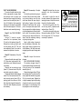
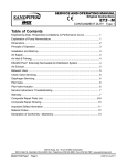
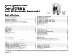
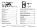
SERVICE & OPERATING MANUAL
Original Instructions
Model S30 Non-Metallic Design Level 2
Table of Contents
Engineering Data and Temperature Limitations.................................................................................. 1
Explanation of Pump Nomenclature.................................................................................................... 2
Performance Curve, Model S30 Non-Metallic Design Level 2............................................................ 3
Dimensions: S30 Non-Metallic............................................................................................................ 4
Metric Dimensions: S30 Non-Metallic................................................................................................. 5
Dimensions: S30 Non-Metallic with Spill Containment........................................................................ 6
Metric Dimensions: S30 Non-Metallic with Spill Containment............................................................. 7
Principle of Pump Operation............................................................................................................... 8
Installation and Start-up...................................................................................................................... 8
Air Supply............................................................................................................................................ 8
Air Valve Lubrication............................................................................................................................ 8
Air Line Moisture................................................................................................................................. 8
Air Inlet and Priming............................................................................................................................ 8
Between Uses..................................................................................................................................... 8
Installation Guide................................................................................................................................. 9
Important Safety Information............................................................................................................. 10
Material Codes...................................................................................................................................11
Troubleshooting................................................................................................................................. 12
Warranty............................................................................................................................................ 12
Composite Repair Parts Drawing...................................................................................................... 13
Overlay Option Drawing.................................................................................................................... 13
Composite Repair Parts List.............................................................................................................. 14
Spill Containment Option for Virgin PTFE Equipped Pumps............................................................. 15
Spill Containment Repair Parts List................................................................................................... 15
Spill Containment Concept................................................................................................................ 16
Spill Containment Option Diaphragm Servicing ............................................................................... 16
Filling Spill Containment Chambers with Liquid................................................................................ 16
Spill Containment Option for TPE Equipped Pumps......................................................................... 17
Spill Containment Repair Parts List................................................................................................... 17
Spill Containment Concept with TPE Diaphragms............................................................................ 18
Spill Containment Option with TPE Diaphragm................................................................................. 18
Air Distribution Valve Assembly Drawing........................................................................................... 19
s30nmdl2sm-rev0211
Main Air Valve Assembly Parts List................................................................................................... 19
Air Distribution Valve Servicing.......................................................................................................... 20
Air Distribution Valve with Stroke Indicator Options.......................................................................... 21
Air Distribution Valve with Stroke Indicator Parts List........................................................................ 21
Air Distribution Valve with Stroke Indicator Servicing........................................................................ 22
Solenoid Shifted Air Valve Drawing................................................................................................... 23
Solenoid Shifted Air Valve Parts List................................................................................................. 23
Solenoid Shifted Air Distribution Valve Option................................................................................... 24
Pilot Valve Assembly Drawing........................................................................................................... 25
Pilot Valve Assembly Parts List......................................................................................................... 25
Pilot Valve Servicing.......................................................................................................................... 26
Diaphragm Service Drawing, Non-Overlay....................................................................................... 27
Diaphragm Service Drawing, with Overlay........................................................................................ 27
Diaphragm Servicing......................................................................................................................... 28
Overlay Diaphragm Service ............................................................................................................. 28
Pumping Hazardous Liquids............................................................................................................. 29
Converting the pump for piping the exhaust air................................................................................. 29
Exhaust Conversion Drawing............................................................................................................ 29
Converted Exhaust Illustration.......................................................................................................... 29
Modular Check Valve Servicing......................................................................................................... 30
Modular Check Valve Drawing.......................................................................................................... 30
Dual Port Option Drawing.................................................................................................................. 31
Dual Porting Options......................................................................................................................... 32
Dual porting of both suction and discharge ends of the pump.......................................................... 32
Single porting of the suction and dual porting of the pump discharge............................................... 32
Dual porting of the suction and single porting of the pump discharge............................................... 32
Leak Detection Options Drawing....................................................................................................... 33
Electronic Leak Detector Installation................................................................................................. 33
Mechanical Leak Detector Installation............................................................................................... 33
Pulse Output Kit Drawing.................................................................................................................. 34
Pulse Output Kit Option..................................................................................................................... 34
Optional Muffler Configurations, Drawing.......................................................................................... 35
EC Declaration of Conformity - Machinery........................................................................................ 36
Warren Rupp, Inc. • A Unit of IDEX Corporation • 800 N. Main St., Mansfield, Ohio 44902 USA
Telephone (419) 524-8388 • Fax (419) 522-7867 • www.warrenrupp.com
©Copyright 2011 Warren Rupp, Inc. All rights reserved.
S30 Non-Metallic
Quality System
ISO9001 Certified
Ball Valve
Environmental
Management System
ISO14001 Certified
Design Level 2
Air Operated
Double Diaphragm Pump
Air Exhaust Side View
ENGINEERING, PERFORMANCE
& CONSTRUCTION DATA
Air Inlet Side View
INTAKE/DISCHARGE PIPE SIZE
3" ANSI Flange or
80mm DIN Flange
CAPACITY
0 to 238 US gallons per minute
(0 to 901 liters per minute)
AIR VALVE
No-lube, no-stall
design
SOLIDS-HANDLING
Up to .71 in. (18mm)
HEADS UP TO
100 psi or 231 ft. of water
(7 bar or 70 meters)
DISPLACEMENT/STROKE
.9 US gallon / 3.41 liter
CAUTION! Maximum Operating Temperature Limit is 180°F for Polypropylene and 250°F for PVDF Models.
Materials
Temperature Limits
Maximum
Minimum
Santoprene®: Injection molded thermoplastic elastomer with no fabric layer. Long mechanical flex life. Excellent abrasion
resistance.
275°F
88°C
-40°F
-40°C
Virgin PTFE: Chemically inert, virtually impervious. Very few chemicals are known to react chemically with PTFE: molten alkali metals,
turbulent liquid or gaseous fluorine and a few fluoro-chemicals such as chlorine trifluoride or oxygen difluoride which readily liberate free
fluorine at elevated temperatures.
350°F
177°C
-35°F
-37°C
Polypropylene
180°F
82°C
32°F
0°C
PVDF
250°F
121°C
0°F
-18°C
For specific applications, always consult “Chemical Resistance Chart” Technical Bulletin
CAUTION: Nonmetallic pumps and plastic components are not UV stabilized. Ultraviolet radiation can damage these parts and negatively affect material properties.
Do not expose to UV light for extended periods of time.
Maximum and Minimum Temperatures are the limits for which these
materials can be operated. Temperatures coupled with pressure affect the
longevity of diaphragm pump components. Maximum life should not be
expected at the extreme limits of the temperature ranges.
SANDPIPER® pumps are designed to be powered only by compressed air.
s30nmdl2sm-rev0211
Model S30 Non-Metallic Page 1
Explanation of Pump Nomenclature
S30 Non-Metallic · Design Level 2· Ball Valve
Check
Model
Pump Pump Valve Design Wetted
Brand Size Type
Level Material
S30B2P1PQAS000.
S30B2P2PQAS000.
S30B2K1KQAS000.
S30B2K2KQAS000.
S30B2P4PQAV000.
S30B2K4KQAV000.
Pump Brand
S=SANDPIPER®
Pump Size
30=3"
Check Valve Type
B=Ball
Design Level
2= Design Level 2
Wetted Material
K=PVDF
P= Polypropylene
s30nmdl2sm-rev0211
S
S
S
S
S
S
30
30
30
30
30
30
B
B
B
B
B
B
2
2
2
2
2
2
Diaphragm Check Valve Materials
1=Santoprene/Santoprene
2=PTFE-Santoprene Backup/PTFE
3=PTFE Pumping, PTFE-Santoprene
Backup Driver/PTFE
4=Santoprene Pumping, Santoprene Driver/Santoprene
Check Valve Seat
K=PVDF
P=Polypropylene
U= Polyurethane/ Polyurethane
Non-Wetted Material Options
A=Painted Aluminum
J=Painted Aluminum PTFE
Q=Epoxy Coated Aluminum
K=PTFE Coated Aluminum
L=PTFE Coated Aluminum with
PTFE Coated Hardware
R=Epoxy Coated Aluminum with PTFE Coated Hardware
P
P
K
K
P
K
Diaphragm/ Check Non-Wetted
Shipping
Check Valve Valve
Material Porting Pump Pump
Kit
Weight
Materials
Seat
Options Options Style Options Options lbs. (kg)
1
2
1
2
4
4
Porting Options
A=ANSI Flange
D=DIN Flange
7=Dual Porting (ANSI)
8=Top Dual Porting (ANSI)
9=Bottom Dual Porting (ANSI)
Pump Style
D=Spill Containment with
Electronic Leak Detection (110V)
E=Spill Containment with
Electronic Leak Detection (220V)
M=Spill Containment with
Mechanical Leak Detection
S=Standard
V=Spill Containment with
Visual Leak Detection
P
P
K
K
P
K
Q
Q
Q
Q
Q
Q
A
A
A
A
A
A
Pump Options
0=None
1=Sound Dampening Muffler
2=Mesh Muffler
3=High temperature Air Valve w/Integral Muffler
4=High temperature
Air Valve with Sound Dampening Muffler
5=High temperature Air Valve w/Mesh Muffler
S
S
S
S
V
V
0
0
0
0
0
0
00.
00.
00.
00.
00.
00.
231 (105)
231 (105)
315 (143)
315 (143)
270 (122)
354 (161)
Kit Options
00.= None
P0.=10-30VDC Pulse Output Kit
P1.=Intrinsically-Safe 5-30VDC,110/120VAC, 220/240VAC Pulse Output Kit
P2.=110/120 or 220/240VAC
Pulse Output Kit
E0.=Solenoid Kit with 24VDC Coil
E1.=Solenoid Kit with 24VDC
Explosion-Proof Coil
E2.=Solenoid Kit with 24VAC/12VDC Coil
E3.=Solenoid Kit with12VDC
Explosion-Proof Coil
E4.=Solenoid Kit with 110VAC Coil
E5.=Solenoid Kit with 110VAC,
60 Hz Explosion-Proof Coil
E6.=Solenoid Kit with 220VAC Coil
E7.=Solenoid Kit with 220VAC,
60 Hz Explosion-Proof Coil
E8.= Solenoid Kit with 110VAC,
50 Hz Explosion-Proof Coil
E9.= Solenoid Kit with 230VAC,
50 Hz Explosion-Proof Coil
SP.=Stroke Indicator Pins
Model S30 Non-Metallic Page 2
Performance Curve, Model S30 Non-Metallic Design Level 2
HEAD
5
4
90
80
80 P
SI (
70
60
2
SI (4
40
0
20 PSI (1
120 (204)
Bar
)
0
140 (238)
Bar)
.36 Bar)
10
0
100 (170)
ar)
I (2.72
30
)
.08 B
40 PS
20
1
5.44
60 P
50
3
Bar
20
50
Air Inle
40
150
t Press
ure
60
250
80
100 120 140 160
U.S. Gallons per minute
350
450
550
Liters per minute
180
650
200
750
METERS
6
I(6.8
NPSHR
7 100
20 (34)
40 (68)
60 (102)
100 P
80 (136)
S
FEET
PSI
BAR
MODEL S30 Non-Metallic Performance Curve
Performance based on the following: elastomer fitted pump, flooded suction, water at ambient conditions.
The use of other materials and varying hydraulic conditions may result in deviations in excess of 5%.
30
25
20
15
10
5
9.1
7.6
6
4.5
3
1.5
220
850
CAPACITY
s30nmdl2sm-rev0211
Model S30 Non-Metallic Page 3
Dimensions: S30 Non-Metallic
Dimensions in Inches
Dimensional tolerance: ±1/8"
Note: Dimensions "A" is from
the vertical center line to the end
of the muffler.
Dimension
Standard Pump
Pulse Output Kit
Sound Dampening Muffler
Mesh Muffler
A
6 9/16"
6 9/16"
13 3/4"
8 13/16"
Note: Porting Flanges are also available with
PN10 80mm DIN bolting configuration.
s30nmdl2sm-rev0211
Model S30 Non-Metallic Page 4
Metric Dimensions: S30 Non-Metallic
Dimensions in Millimeters
Dimensional tolerance: ± 3mm
Note: Dimensions "A" is from
the vertical center line to the end
of the muffler.
Dimension
Standard Pump
Pulse Output Kit
Sound Dampening Muffler
Mesh Muffler
A
6 9/16"
6 9/16"
13 3/4"
8 13/16"
Note: Porting Flanges are also available
with PN10 80mm DIN bolting configuration.
s30nmdl2sm-rev0211
Model S30 Non-Metallic Page 5
Dimensions: S30 Non-Metallic
with Spill Containment
Note: Dimensions "A" is from
the vertical center line to the
end of the muffler.
Note: Dimensions "B" is from
the opposite side of the pump
to the end of the muffler.
Dimensions in Inches
Dimensional tolerance: ±1/8"
Dimension
Standard Pump
Pulse Output Kit
Sound Dampening Muffler
Mesh Muffler
A
6 9/16"
6 9/16"
13 3/4"
8 13/16"
B
12 11/16"
12 11/16"
22 9/32"
14 15/16"
Note: Porting Flanges are also available with
PN10 40mm DIN bolting configuration.
s30nmdl2sm-rev0211
Model S30 Non-Metallic Page 6
Metric Dimensions: S30 Non-Metallic
with Spill Containment
Dimensions in Millimeters
Dimensional tolerance: ± 3mm
Dimension
Standard Pump
Pulse Output Kit
Sound Dampening Muffler
Mesh Muffler
A
167mm
167mm
349mm
225mm
B
322mm
322mm
579mm
380mm
Note: Porting Flanges are also available with
PN10 80mm DIN bolting configuration.
s30nmdl2sm-rev0211
Model S30 Non-Metallic Page 7
PRINCIPLE OF PUMP OPERATION
This ball type check valve pump
is powered by compressed air and is
a 1:1 ratio design. The inner side of
one diaphragm chamber is alternately
pressurized while simultaneously
exhausting the other inner chamber.
This causes the diaphragms, which
are connected by a common rod
secured by plates to the centers of the
diaphragms, to move in a reciprocating
action. (As one diaphragm performs the
discharge stroke the other diaphragm is
pulled to perform the suction stroke in
the opposite chamber.) Air pressure is
applied over the entire inner surface of
the diaphragm while liquid is discharged
from the opposite side of the diaphragm.
The diaphragm operates in a balanced
condition during the discharge stroke
which allows the pump to be operated
at discharge heads over 200 feet (61
meters) of water.
For maximum diaphragm life, keep
the pump as close to the liquid being
pumped as possible. Positive suction
head in excess of 10 feet of liquid
(3.048 meters) may require a back
pressure regulating device to maximize
diaphragm life.
Alternate pressurizing and
exhausting of the diaphragm chamber
is performed by an externally mounted,
pilot operated, four way spool type
air distribution valve. When the spool
shifts to one end of the valve body, inlet
pressure is applied to one diaphragm
chamber and the other diaphragm
chamber exhausts. When the spool
shifts to the opposite end of the valve
body, the pressure to the chambers
s30nmdl2sm-rev0211
is reversed. The air distribution valve
spool is moved by a internal pilot valve
which alternately pressurizes one end
of the air distribution valve spool while
exhausting the other end. The pilot valve
is shifted at each end of the diaphragm
stroke when a actuator plunger is
contacted by the diaphragm plate. This
actuator plunger then pushes the end
of the pilot valve spool into position to
activate the air distribution valve.
The chambers are connected with
manifolds with a suction and discharge
check valve for each chamber,
maintaining flow in one direction
through the pump.
INSTALLATION AND START-UP
Locate the pump as close to the
product being pumped as possible.
Keep the suction line length and
number of fittings to a minimum. Do not
reduce the suction line diameter.
For installations of rigid piping,
short sections of flexible hose should
be installed between the pump
and the piping. The flexible hose
reduces vibration and strain to the
pumping system. A surge suppressor
is recommended to further reduce
pulsation in flow.
AIR SUPPLY
Air supply pressure cannot exceed
100 psi (7 bar). Connect the pump
air inlet to an air supply of sufficient
capacity and pressure required for
desired performance. When the air
supply line is solid piping, use a short
length of flexible hose not less than ½"
(13mm) in diameter between the pump
and the piping to reduce strain to the
piping. The weight of the air supply line,
regulators and filters must be supported
by some means other than the air
inlet cap. Failure to provide support
for the piping may result in damage
to the pump. A pressure regulating
valve should be installed to insure
air supply pressure does not exceed
recommended limits.
AIR VALVE LUBRICATION
The air distribution valve and the
pilot valve are designed to operate
WITHOUT lubrication. This is the
preferred mode of operation. There may
be instances of personal preference
or poor quality air supplies when
lubrication of the compressed air
supply is required. The pump air system
will operate with properly lubricated
c o m p r e s s e d a i r s u p p l y. P r o p e r
lubrication requires the use of an air line
lubricator (available from Warren Rupp)
set to deliver one drop of SAE 10 nondetergent oil for every 20 SCFM (9.4
liters/sec.) of air the pump consumes
at the point of operation. Consult the
pump’s published Performance Curve
to determine this.
AIR INLET AND PRIMING
To start the pump, open the air
valve approximately ½ to ¾ turn. After
the pump primes, the air valve can be
opened to increase air flow as desired.
If opening the valve increases cycling
rate, but does not increase the rate
of flow, cavitation has occurred. The
valve should be closed slightly to
obtain the most efficient air flow to pump
flow ratio.
BETWEEN USES
When the pump is used for materials
that tend to settle out or solidify when
not in motion, the pump should be
flushed after each use to prevent
damage. (Product remaining in the
pump between uses could dry out or
settle out. This could cause problems
with the diaphragms and check valves
at restart.) In freezing temperatures
the pump must be completely drained
between uses in all cases.
AIR LINE MOISTURE
Water in the compressed air supply
can create problems such as icing or
freezing of the exhaust air, causing
the pump to cycle erratically or stop
operating. Water in the air supply can
be reduced by using a point-of-use
air dryer to supplement the user’s air
drying equipment. This device removes
water from the compressed air supply
and alleviates the icing or freezing
problems.
Model S30 Non-Metallic Page 8
INSTALLATION GUIDE
Top Discharge Ball Valve Unit
1
Available from
Warren Rupp
1 Surge Suppressor
Surge
Suppressor
Limited to
100 psi
2 020-051-000 Filter/Regulator
3 Air Dryer
CAUTION
The air exhaust should be
piped to an area for safe
disposition of the product
being pumped, in the event
of a diaphragm failure.
3
2
s30nmdl2sm-rev0211
Model S30 Non-Metallic Page 9
RECYCLING
Many components of SANDPIPER® AODD
pumps are made of recyclable materials (see
chart on page 11 for material specifications).
We encourage pump users to recycle worn
out parts and pumps whenever possible, after
any hazardous pumped fluids are thoroughly
flushed.
IMPORTANT SAFETY
INFORMATION
IMPORTANT
Read these safety warnings
and instructions in this
manual completely, before
installation and start-up
of the pump. It is the responsibility of the
purchaser to retain this manual for reference.
Failure to comply with the recommendations
stated in this manual will damage the pump,
and void factory warranty.
CAUTION
Before pump operation,
inspect all gasketed
fasteners for looseness
caused by gasket creep. Retorque loose fasteners to
prevent leakage. Follow recommended torques
stated in this manual.
WARNING
Before maintenance
or repair, shut off the
compressed air line,
bleed the pressure, and
disconnect the air line from
the pump. The discharge
line may be pressurized and must be bled of
its pressure.
WARNING
This pump is pressurized
internally with air pressure
during operation. Always
make certain that all bolting
is in good condition and
that all of the correct
bolting is reinstalled during assembly.
WARNING
When used for toxic or
aggressive fluids, the pump
should always be flushed
clean prior to disassembly.
WARNING
Before doing any
maintenance on the pump,
be certain all pressure is
completely vented from the
pump, suction, discharge,
piping, and all other
openings and connections. Be certain the air
supply is locked out or made non‑operational,
so that it cannot be started while work is being
done on the pump. Be certain that approved
eye protection and protective clothing are worn
all times in the vicinity of the pump. Failure to
follow these recommendations may result in
serious injury or death.
WARNING
In the event of diaphragm
rupture, pumped material
may enter the air end of the
pump, and be discharged
into the atmosphere. If
pumping a product which is hazardous or toxic,
the air exhaust must be piped to an appropriate
area for safe disposition.
s30nmdl2sm-rev0211
WARNING
Airborne particles and
loud noise hazards.
Wear ear and eye
protection.
Model S30 Non-Metallic Page 10
Material Codes
The Last 3 Digits of Part Number
000
010
012
015
020
025
080
100
110
111
112
113
114
115
117
120
123
148
149
150
151
152
154
155
156
157
158
159
162
165
166
170
175
180
305
Assembly, sub-assembly;
and some purchased items
Cast Iron
Powered Metal
Ductile Iron
Ferritic Malleable Iron
Music Wire
Carbon Steel, AISI B-1112
Alloy 20
Alloy Type 316 Stainless Steel
Alloy Type 316 Stainless Steel
(Electro Polished)
Alloy C
Alloy Type 316 Stainless Steel
(Hand Polished)
303 Stainless Steel
302/304 Stainless Steel
440-C Stainless Steel (Martensitic)
416 Stainless Steel
(Wrought Martensitic)
410 Stainless Steel
(Wrought Martensitic)
Hardcoat Anodized Aluminum
2024-T4 Aluminum
6061-T6 Aluminum
6063-T6 Aluminum
2024-T4 Aluminum (2023-T351)
Almag 35 Aluminum
356-T6 Aluminum
356-T6 Aluminum
Die Cast Aluminum Alloy #380
Aluminum Alloy SR-319
Anodized Aluminum
Brass, Yellow, Screw Machine Stock
Cast Bronze, 85-5-5-5
Bronze, SAE 660
Bronze, Bearing Type,
Oil Impregnated
Die Cast Zinc
Copper Alloy
Carbon Steel, Black Epoxy Coated
s30nmdl2sm-rev0211
306
307
308
309
310
313
330
331
332
333
335
336
337
340
342
351
353
354
355
356
357
358
359
360
361
363
364
365
366
368
370
371
Carbon Steel, Black PTFE Coated
Aluminum, Black Epoxy Coated
Stainless Steel, Black PTFE Coated
Aluminum, Black PTFE Coated
PVDF Coated
Aluminum, White Epoxy Coated
Zinc Plated Steel
Chrome Plated Steel
Aluminum, Electroless Nickel Plated
Carbon Steel, Electroless
Nickel Plated
Galvanized Steel
Zinc Plated Yellow Brass
Silver Plated Steel
Nickel Plated
Filled Nylon
Food Grade Santoprene
Geolast; Color: Black
Injection Molded #203-40
Santoprene- Duro 40D +/-5;
Color: RED
Thermal Plastic
Hytrel
Injection Molded Polyurethane
Urethane Rubber
(Some Applications)
(Compression Mold)
Urethane Rubber
Nitrile Rubber Color coded: RED
Nitrile
FKM (Fluorocarbon).
Color coded: YELLOW
E.P.D.M. Rubber.
Color coded: BLUE
Neoprene Rubber.
Color coded: GREEN
Food Grade Nitrile
Food Grade EPDM
Butyl Rubber
Color coded: BROWN
Philthane (Tuftane)
374
375
378
379
405
408
425
426
440
465
500
501
502
503
505
506
520
540
541
542
544
550
551
552
553
555
556
558
570
580
590
591
592
600
601
602
603
604
606
Carboxylated Nitrile
Fluorinated Nitrile
High Density Polypropylene
Conductive Nitrile
Cellulose Fibre
Cork and Neoprene
Compressed Fibre
Blue Gard
Vegetable Fibre
Fibre
Delrin 500
Delrin 570
Conductive Acetal, ESD-800
Conductive Acetal, Glass-Filled
Acrylic Resin Plastic
Delrin 150
Injection Molded PVDF
Natural color
Nylon
Nylon
Nylon
Nylon Injection Molded
Polyethylene
Glass Filled Polypropylene
Unfilled Polypropylene
Unfilled Polypropylene
Polyvinyl Chloride
Black Vinyl
Conductive HDPE
Rulon II
Ryton
Valox
Nylatron G-S
Nylatron NSB
PTFE (virgin material)
Tetrafluorocarbon (TFE)
PTFE (Bronze and moly filled)
Filled PTFE
Blue Gylon
PTFE
PTFE
607
608
610
611
632
633
634
635
637
638
639
643
644
656
661
666
668
Envelon
Conductive PTFE
PTFE Encapsulated Silicon
PTFE Encapsulated FKM
Neoprene/Hytrel
FKM/PTFE
EPDM/PTFE
Neoprene/PTFE
PTFE, FKM/PTFE
PTFE, Hytrel/PTFE
Nitrile/TFE
Santoprene®/EPDM
Santoprene®/PTFE
Santoprene Diaphragm and
Check Balls/EPDM Seats
EPDM/Santoprene
FDA Nitrile Diaphragm,
PTFE Overlay, Balls, and Seals
PTFE, FDA Santoprene/PTFE
Delrin and Hytrel are registered
tradenames of E.I. DuPont.
Gylon is a registered tradename
of Garlock, Inc.
Nylatron is a registered tradename
of Polymer Corp.
Santoprene is a registered tradename
of Exxon Mobil Corp.
Rulon II is a registered tradename
of Dixion Industries Corp.
Ryton is a registered tradename
of Phillips Chemical Co.
Valox is a registered tradename
of General Electric Co.
PortaPump, Tranquilizer and
SludgeMaster are registered tradenames
of Warren Rupp, Inc.
Model S30 Non-Metallic Page 11
TROUBLESHOOTING
Possible Symptoms:
• Pump will not cycle.
• Pump cycles, but produces no flow.
• Pump cycles, but flow rate is
unsatisfactory.
• Pump cycle seems unbalanced.
• Pump cycle seems to produce
excessive vibration.
What to Check: Excessive suction lift
in system.
Corrective Action: For lifts exceeding
20 feet (6 meters), filling the pumping
chambers with liquid will prime the
pump in most cases.
What to Check: Excessive flooded
suction in system.
Corrective Action: For flooded
conditions exceeding 10 feet (3 meters)
of liquid, install a back pressure device.
What to Check: System head exceeds
air supply pressure.
Corrective Action: Increase the
inlet air pressure to the pump. Most
diaphragm pumps are designed for 1:1
pressure ratio at zero flow.
What to Check: Air supply pressure or
volume exceeds system head.
Corrective Action: Decrease inlet
air pressure and volume to the
pump as calculated on the published
PERFORMANCE CURVE. Pump is
cavitating the fluid by fast cycling.
s30nmdl2sm-rev0211
What to Check: Undersized suction
line.
Corrective Action: Meet or exceed
pump connection recommendations
shown on the DIMENSIONAL
DRAWING.
What to Check: Restricted or
undersized air line.
Corrective Action: Install a larger
air line and connection. Refer to air
inlet recommendations shown in your
pump’s SERVICE MANUAL.
What to Check: Check ESADS+Plus,
the Externally Serviceable Air
Distribution System of the pump.
Corrective Action: Disassemble and
inspect the main air distribution valve,
pilot valve and pilot valve actuators.
Refer to the parts drawing and air valve
section of the SERVICE MANUAL.
Check for clogged discharge or closed
valve before reassembly.
What to Check: Rigid pipe connections
to pump.
Corrective Action: Install flexible
connectors and a surge suppressor.
What to Check: Blocked air exhaust
muffler.
Corrective Action: Remove muffler
screen, clean or de-ice and reinstall.
Refer to the Air Exhaust section of your
pump SERVICE MANUAL.
What to Check: Pumped fluid in air
exhaust muffler.
Corrective Action: Disassemble
pump chambers. Inspect for diaphragm
rupture or loose diaphragm plate
assembly. Refer to the Diaphragm
Replacement section of your pump
SERVICE MANUAL.
What to Check: Suction side air
leakage or air in product.
Corrective Action: Visually inspect
all suction side gaskets and pipe
connections.
What to Check: Obstructed check
valve.
Corrective Action: Disassemble the
wet end of the pump and manually
dislodge obstruction in the check valve
pocket. Refer to the Check Valve
section of the pump SERVICE MANUAL
for disassembly instructions.
What to Check: Worn or misaligned
check valve or check valve seat.
Corrective Action: Inspect check
valves and seats for wear and proper
seating. Replace if necessary. Refer
to Check Valve section of the pump
SERVICE MANUAL for disassembly
instructions.
What to Check: Blocked suction line.
Corrective Action: Remove or flush
obstruction. Check and clear all suction
screens and strainers.
What to Check: Blocked discharge
line.
Corrective Action: Check for
obstruction or closed discharge line
valves.
What to Check: Blocked pumping
chamber.
Corrective Action: Disassemble
and inspect the wetted chambers
of the pump. Remove or flush any
obstructions. Refer to the pump
SERVICE MANUAL for disassembly
instructions.
What to Check: Entrained air or vapor
lock in one or both pumping chambers.
Corrective Action: Purge chambers
through tapped chamber vent plugs.
PURGING THE CHAMBERS OF
AIR CAN BE DANGEROUS! Contact
the Warren Rupp Technical Services
Department before performing this
procedure. A model with top-ported
discharge will reduce or eliminate
problems with entrained air.
If your pump continues to perform
below your expectations, contact your
local Warren Rupp Distributor or factory
Technical Services Group for a service
evaluation.
WARRANTY
Refer to the enclosed Warren Rupp
Warranty Certificate.
Model S30 Non-Metallic Page 12
Composite Repair Parts Drawing
AVAILABLE SERVICE AND CONVERSION KITS
476-176-000 AIR END KIT
Seals, O-rings, Gaskets, Retaining Rings, Air Valve Sleeve
& Spool Set and Pilot Valve Assembly.
476-177-000* AIR END KIT (for Stroke Indicator Option)
Seals, O-rings, Gaskets, Retaining Rings, Air Valve Sleeve
& Spool Set and Pilot Valve Assembly.
476-140-354 WETTED END KIT
Santoprene Diaphragms, Santoprene Balls and TFE Seals.
476-140-654 WETTED END KIT
Santoprene Diaphragms, PTFE Overlay Diaphragms, TFE Balls and TFE Seals.
476-143-354 WETTED END KIT (for Polypropylene Spill Containment)
Santoprene Diaphragms, PTFE Overlay Diaphragms, PTFE Pumping Diaphragms, PTFE Balls and PTFE Seals.
476-143-655 WETTED END KIT (for PVDF Spill Containment)
Santoprene Diaphragms, PTFE Overlay Diaphragms,
PTFE Pumping Diaphragms, PTFE Balls and PTFE Seals.
HARDWARE KITS
475-173-308 PTFE Coated Stainless Steel Capscrews, Hex Nuts,
Washers and Support Rod
475-174-308 (For use with Spill Containment Options)
ELECTRONIC LEAK DETECTOR KITS
032-037-000 100VAC
50Hz
or 110-120VAC
50-60Hz
or 220-240VAC
50-60Hz
032-045-000 12-32VDC
s30nmdl2sm-rev0211
Model S30 Non-Metallic Page 13
Composite Repair Parts List
ITEM
1
2
3
4
5
6
7
8
9
10
11
12
13
14
15
16
17
PART NUMBER
031-140-000
031-140-002
031-141-000
095-089-000
050-039-354
050-039-357
050-039-600
114-021-156
114-021-307
114-021-309
114-021-332
115-133-080
115-133-305
115-133-306
115-133-333
132-019-360
135-032-506
165-099-156
165-099-307
165-099-309
165-099-332
170-017-115
170-017-308
170-052-115
170-052-308
170-111-115
170-111-308
170-112-115
170-112-308
171-004-115
171-053-115
171-053-308
196-151-520
196-151-552
196-152-156
196-152-307
196-152-309
196-152-332
286-077-354
286-077-357
s30nmdl2sm-rev0211
DESCRIPTION
QTY
Air Valve Assembly
1
Air Valve Assembly w/ PTFE coated Hardware 1
Air Valve Assembly (No Integral Muffler)
1
Pilot Valve Assembly
1
Ball, Check
4
Ball, Check
4
Ball, Check
4
Intermediate Assembly
1
Intermediate Assembly
1
Intermediate Assembly
1
Intermediate Assembly
1
Bracket, Mounting
2
Bracket, Mounting
2
Bracket, Mounting
2
Bracket, Mounting
2
Bumper, Diaphragm
2
Bushing, Plunger
2
Cap, Air Inlet
1
Cap, Air Inlet
1
Cap, Air Inlet
1
Cap, Air Inlet
1
Capscrew, Hex HD 5/8-11 x 1.75
4
Capscrew, Hex HD 5/8-11 x 1.75
4
Capscrew, Hex HD 3/8-16 x 2.25
4
Capscrew, Hex HD 3/8-16 x 2.25
4
Capscrew, Hex HD 5/8-11 x 3.25
4
Capscrew, Hex HD 5/8-11 x 3.25
4
Capscrew, Hex HD 5/8-11 x 3.75
32
Capscrew, Soc HD 5/8-11 x 3.75
32
Capscrew, Soc HD 1/2-13 x 1.25
6
Capscrew, Soc HD 3/8-16 X 2.75
4
Capscrew, Soc HD 3/8-16 X 2.75
4
Chamber, Outer
2
Chamber, Outer
2
Chamber, Inner
2
Chamber, Inner
2
Chamber, Inner
2
Chamber, Inner
2
Diaphragm
2
Diaphragm
2
ITEM
PART NUMBER
DESCRIPTION
18
19
20
21
22
23
24
25
27
28
29
30
31
32
33
34
35
36
37
38
39
40
41
286-078-600
312-103-520
312-103-552
360-090-360
360-091-360
360-092-360
360-093-360
518-133-520
518-133-520E
518-133-552
518-133-552E
530-027-000
530-010-000
545-009-110
545-009-308
560-001-360
612-161-520
612-161-552
612-162-150
620-017-115
670-047-520
670-047-552
685-051-120
685-052-115
685-052-308
720-010-375
720-039-600
720-043-600
722-076-520
722-076-552
770-055-520
770-055-552
770-059-520
770-059-552
901-047-115
901-047-308
901-048-115
901-048-308
Diaphragm, Overlay
Elbow
Elbow
Gasket, Air Inlet
Gasket, Inner Chamber
Gasket, Pilot Valve
Gasket, Main Air Valve
Manifold
Manifold, 80mm DIN
Manifold
Manifold, 80mm DIN
Muffler
Muffler Nut, Hex 5/8
Nut, Hex 5/8
O-ring
Assembly, Outer Diaphragm Plate
Assembly, Outer Diaphragm Plate
Assembly, Inner Diaphragm Plate
Plunger, Actuator
Retainer, Ball
Retainer, Ball
Rod, Diaphragm
Rod, Support
Rod, Support
Seal, Diaphragm Rod
Seal, Manifold Spacer
Seal, Check Valve Assembly
Seat, Check Valve
Seat, Check Valve
Spacer, Manifold
Spacer, Manifold
Spacer, Manifold (PTFE Overlays Only)
Spacer, Manifold (PTFE Overlays Only)
Washer, Flat 5/8"
Washer, Flat 5/8"
Washer, Flat 3/8"
Washer, Flat 3/8"
NOT SHOWN:
535-069-000
QTY
2
4
4
1
2
1
1
2
2
2
2
1
1
72
72
2
2
2
2
2
4
4
1
2
2
2
8
8
4
4
4
4
4
4
140
140
8
8
Nameplate
Model S30 Non-Metallic Page 14
Spill Containment Option for Virgin PTFE
Equipped Pumps Drawing
Discharge
Manifold
Suction
Manifold
s30nmdl2sm-rev0211
S30 Spill Containment Repair Parts List for
Virgin PTFE Equipped Pumps
ItemPart Number
1
031-146-000
031-147-000
43 170-113-115
170-113-308
44 170-115-115
170-115-308
45 196-156-552
196-156-600
46 286-079-600
47 518-135-520
518-135-520E
518-135-552
518-135-552E
48 538-022-110
538-022-308
49 560-078-611
50 618-003-110
618-003-308
51 618-025-110
618-025-308
52 618-031-110
618-031-308
53 770-061-600
770-061-552
54 835-005-110
835-005-308
55 860-057-606
56 866-060-110
Description
Air Valve Assembly
(replaces 031-140-000)
Air Valve Assembly
(replaces 031-141-000)
Capscrew, Hex HD 5/8-11 x 6.00
Capscrew, Hex HD 5/8-11 x 6.00
Capscrew, Hex HD 5/8-11 x 4.00
Capscrew, Hex HD 5/8-11 x 4.00
Chamber, Spill Containment
Chamber, Spill Containment
Diaphragm, Pumping
Manifold
Manifold, 80mm DIN
Manifold
Manifold, 80mm DIN
Nipple, Pipe
Nipple, Pipe
O-Ring
Plug, Pipe
Plug, Pipe
Plug, Boss
Plug, Boss
Plug, Boss
Plug, Boss
Spacer, Manifold
Spacer, Manifold
Tee, Pipe
Tee, Pipe
Tube, Sight
Connector, Tube
Qty
1
1
16
16
4
4
2
2
2
2
2
2
2
4
4
8
4
4
4
4
4
4
4
4
4
4
2
4
Model S30 Non-Metallic Page 15
SPILL CONTAINMENT FOR PTFE
EQUIPPED PUMPS CONCEPT
The Spill Containment option
prevents the air end components from
being contaminated or damaged when
a pumping diaphragm ruptures while
pumping caustic or toxic materials. It
also helps to protect the environment.
With the installation of optional leak
detectors (either mechanical or
electronic) the diaphragm rupture can
be detected. The pump can then be
shut down and repaired before any
caustic or toxic materials can enter
the air end and be exhausted into the
surrounding environment.
SPILL CONTAINMENT OPTION
Diaphragm servicing
To service the diaphragms first
shut off the suction, then shut off the
discharge lines to the pump. Next shut
off the compressed air supply, bleed
the pressure from the pump, and
disconnect the air supply line from the
pump. Drain any remaining pumped
liquid from the pump. Remove the pump
before servicing.
Next, drain the fluid from the Spill
Containment chambers. This can be
done by removing the bottom plug
(item 50) from each Spill Containment
chamber.
After the fluid from the Spill
Containment chambers has been
drained, the wet end components
can now be removed. See diaphragm
servicing section for detailed
instructions. The Spill Containment
option has two additional virgin PTFE
pumping diaphragms (item 46).
s30nmdl2sm-rev0211
FILLING SPILL CONTAINMENT
CHAMBERS WITH LIQUID
THE CHAMBERS ARE FILLED
WITH WATER AT THE FACTORY.
If you prefer to substitute another
liquid, to prevent system contamination
consult the factory first to determine
compatibility of the substitute with
pump construction.
Follow the steps listed here to
replace the liquid in the pump after
disassembly or liquid loss:
1. Drain the fluid in the Spill
Containment chambers by removing
the bottom two boss plugs (items 50).
Replace the bottom two boss plugs
after the fluid is drained.
2. Remove the eight capscrews
(item 11) fastening the discharge
manifold and elbows to the outer
chambers (items 15). The discharge
manifolds and elbows can now be
removed.
3. Remove the top two boss plugs
(items 50). The Spill Containment
chambers are filled through the
exposed ports.
4. Apply air pressure to the air
distribution valve. Install safety clip
(item 1-F) into the smaller unthreaded
hole in one end cap. This locks the
valve spool to one side, keeping the
pump from shifting.
5. Face the side of the pump with
the installed safety clip. If the safety
clip is installed in the top end cap, fill
the left spill containment chamber. If
the safety clip is installed on the bottom
end cap, fill the right Spill Containment
chamber. The volume of fluid is 3770
ml (127.5 fl. oz.). It is important that
the exact amount of fluid is used. Too
little or too much fluid causes premature
diaphragm failure and erratic pumping.
6. Loosely reinstall one boss plug
to the filled Spill Containment chamber.
7. Shut off air supply. Remove safety
clip. Adjust the air line regulator so that
air pressure slowly fills the pump. The
diaphragm expands, forcing the fluid
in the chamber to be slowly displaced.
When the pump shifts to the opposite
side, quickly install the safety clip.
8. Loosen the top boss plug on the
filled chambers. This allows fluid in the
chamber to purge trapped air from the
chamber. This can be seen by watching
the column of fluid in the sight tube.
When fluid appears at the top of the
port, quickly tighten the boss plug. Fluid
loss of 1 to 2ml is acceptable.
9. Tilt the pump so the uppermost
pipe tee (item 53) is in the vertical
position. Loosen the pipe plug (item
49). This will allow trapped air to
purge through the pipe tee. When fluid
appears at the tee opening, reinstall
the pipe plug.
NOTE: If all air is not purged using
this procedure, remove the check valve
components from the top port of the
outer chamber (item 15). Apply manual
pressure to the pumping diaphragm by
inserting a blunt instrument into the top
port of the outer chamber and applying
pressure to the diaphragm. Loosen the
pipe plug (item 49) allowing the fluid
to purge any remaining trapped air.
Reinstall the plug.
10. Repeat steps 5 through 9 to fill
opposite Spill Containment chamber.
11. Reinstall the check valve
components, discharge manifold and
elbows to the pump. The pump is now
ready for operation.
IMPORTANT
Read these instructions
c o m p l e t e l y, b e f o r e
installation and start-up.
It is the responsibility of
the purchaser to retain
this manual for reference. Failure to
comply with the recommendations stated
in this manual will damage the pump, and
void factory warranty.
Model S30 Non-Metallic Page 16
Spill Containment Option for TPE
Equipped Pumps Drawing
Discharge
Manifold
Suction
Manifold
s30nmdl2sm-rev0211
S30 Spill Containment for TPE Equipped Pumps
Repair Parts List
ItemPart Number
1
031-146-000
031-147-000
43 170-113-115
170-113-308
44 170-115-115
170-115-308
45 196-156-552
196-156-600
46 286-080-354
47 518-135-520
518-135-520E
518-135-552
518-135-552E
48 538-022-110
538-022-308
49 560-078-611
50 618-003-110
618-003-308
51 618-025-110
618-025-308
52 618-031-110
618-031-308
53 770-061-600
770-061-552
54 835-005-110
835-005-308
55 860-057-606
56 866-060-110
Description
Air Valve Assembly
(replaces 031-140-000)
Air Valve Assembly
(replaces 031-141-000)
Capscrew, Hex HD 5/8-11 x 6.00
Capscrew, Hex HD 5/8-11 x 6.00
Capscrew, Hex HD 5/8-11 x 4.00
Capscrew, Hex HD 5/8-11 x 4.00
Chamber, Spill Containment
Chamber, Spill Containment
Diaphragm, Pumping
Manifold, Spill Containment
Manifold, 80mm DIN
Manifold, Spill Containment
Manifold, 80mm DIN
Pipe, Nipple
Pipe, Nipple
O-ring
Plug, Pipe
Plug, Pipe
Plug, Boss
Plug, Boss
Plug, Boss
Plug, Boss
Spacer, Manifold
Spacer, Manifold
Tee, Pipe
Tee, Pipe
Tube, Sight
Connector, Tube
Qty
1
1
16
16
4
4
2
2
2
2
2
2
2
4
4
8
4
4
4
4
4
4
4
4
4
4
2
4
Model S30 Non-Metallic Page 17
SPILL CONTAINMENT FOR TPE
EQUIPPED PUMPS CONCEPT
The Spill Containment option
prevents the air end components from
being contaminated or damaged when
a pumping diaphragm ruptures while
pumping caustic or toxic materials. It
also helps to protect the environment.
With the installation of optional leak
detectors (either mechanical or
electronic) the diaphragm rupture can
be detected. The pump can then be
shut down and repaired before any
caustic or toxic materials can enter
the air end and be exhausted into the
surrounding environment.
Spill Containment OPTION
Diaphragm servicing
To service the diaphragms first
shut off the suction, then shut off the
discharge lines to the pump. Next shut
off the compressed air supply, bleed
the pressure from the pump, and
disconnect the air supply line from the
pump. Drain any remaining pumped
liquid from the pump. Remove the pump
before servicing.
Next, drain the fluid from the Spill
Containment chambers. This can be
done by removing the bottom plug
(item 50) from each Spill Containment
chamber.
After the fluid from the Spill
Containment chambers has been
drained, the wet end components
can now be removed. See diaphragm
servicing section for detailed
instructions. The Spill Containment
option has two additional TPE pumping
diaphragms (item 46).
s30nmdl2sm-rev0211
FILLING Spill Containment
CHAMBERS WITH LIQUID
THE CHAMBERS ARE FILLED
WITH WATER AT THE FACTORY.
If you prefer to substitute another
liquid, to prevent system contamination
consult the factory first to determine
compatibility of the substitute with
pump construction.
Follow the steps listed here to
replace the liquid in the pump after
disassembly or liquid loss:
1. Drain the fluid in the Spill
Containment chambers by removing
the bottom two boss plugs (items 50).
Replace the bottom two boss plugs
after the fluid is drained.
2. Remove the eight capscrews
(item 11) fastening the discharge
manifold and elbows to the outer
chambers (items 15). The discharge
manifolds and elbows can now be
removed.
3. Remove the top two boss plugs
(items 50). The Spill Containment
chambers are filled through the
exposed ports.
4. Apply air pressure to the air
distribution valve. Install safety clip
(item 1-F) into the smaller unthreaded
hole in one end cap. This locks the
valve spool to one side, keeping the
pump from shifting.
5. Face the side of the pump with
the installed safety clip. If the safety
clip is installed in the top end cap, fill
the left Spill Containment chamber. If
the safety clip is installed on the bottom
end cap, fill the right Spill Containment
chamber. The volume of fluid is 3770
ml (127.5 fl. oz.). It is important that the
exact amount of fluid is used. Too little
or too much fluid causes premature
diaphragm failure and erratic pumping.
6. Loosely reinstall one boss plug to
the filled Spill Containment chamber.
7. Shut off air supply. Remove safety
clip. Adjust the air line regulator so that
air pressure slowly fills the pump. The
diaphragm expands, forcing the fluid
in the chamber to be slowly displaced.
When the pump shifts to the opposite
side, quickly install the safety clip.
8. Loosen the top boss plug on the
filled chambers. This allows fluid in the
chamber to purge trapped air from the
chamber. This can be seen by watching
the column of fluid in the sight tube.
When fluid appears at the top of the
port, quickly tighten the boss plug. Fluid
loss of 1 to 2ml is acceptable.
9. Tilt the pump so the uppermost
pipe tee (item 53) is in the vertical
position. Loosen the pipe plug (item
49). This will allow trapped air to
purge through the pipe tee. When fluid
appears at the tee opening, reinstall
the pipe plug.
NOTE: If all air is not purged using
this procedure, remove the check valve
components from the top port of the
outer chamber (item 15). Apply manual
pressure to the pumping diaphragm by
inserting a blunt instrument into the top
port of the outer chamber and applying
pressure to the diaphragm. Loosen the
pipe plug (item 49) allowing the fluid
to purge any remaining trapped air.
Reinstall the plug.
10. Repeat steps 5 through 9 to fill
opposite Spill Containment chamber.
11. Reinstall the check valve
components, discharge manifold and
elbows to the pump. The pump is now
ready for operation.
IMPORTANT
Read these instructions
c o m p l e t e l y, b e f o r e
installation and startup. It is the responsibility
of the purchaser to
retain this manual for
reference. Failure to comply with the
recommendations stated in this manual
will damage the pump, and void factory
warranty.
Model S30 Non-Metallic Page 18
Air Distribution Valve Assembly Drawing
S30 Design Level 2
Main Air Valve Assembly Parts List
Item Part Number Description
1-J
1-H
1-G
1-D
1-G
1-E
1-F
1-C
1-A
1-A
1
1-A
1-B
1-C
1-D
1-E
1-F
1-G
1-H
1-J
031-140-000
031-139-000
095-094-551
132-029-552
165-096-551
165-115-552
530-028-550
560-020-360
675-044-115
710-015-115
Main Air Valve Assembly
Spool Assembly
Body, Air Valve
Bumper
Cap, Muffler
Cap, End
Muffler
O-Ring
Ring, Retaining
Screw, Self-tapping
For pumps equipped with PTFE Coated Hardware
1
031-140-002
Air Valve Assembly
(Includes all items used on 031-140-000 except:)
1-J
710-015-308
Screw Self tapping
1-H 675-044-308
Ring, Retaining
Qty
1
1
1
2
1
2
1
8
2
4
1
4
2
For pumps equipped with PTFE coated hardware option:
1
031-141-000
Air Valve Assembly
1
(Includes all items used on 031-140-000 minus
items 1-D, 1-F & 1-J)
For pumps with alternate Mesh or Sound Dampening mufflers
or piped exhaust:
1
031-041-002
Air Valve Assembly
1
(Includes all items used on 031-141-000 except:)
1-H 675-044-308
Ring, Retaining
2
1-B
1-G
1-E
1-C
1-H
s30nmdl2sm-rev0211
Model S30 Non-Metallic Page 19
AIR DISTRIBUTION VALVE
SERVICING
To service the air valve first shut off
the compressed air, bleed the pressure
from the pump, and disconnect the air
supply line from the pump.
Inspect the inner diameter of the
sleeve (part of item 1-A) for dirt,
scratches, or other contaminates.
Remove the sleeve if needed and
replace both the sleeve and spool with
a new sleeve and spool set (item 1-A).
STEP #1: See Composite Repair
and Parts Drawing.
Using a 5/16" Allen wrench, remove
the four hex socket capscrews (item 14)
and four flat washers (item 41). Remove
the air valve assembly from the pump.
Remove and inspect gasket (item
23) for cracks or damage. Replace
gasket if needed.
STEP #3: Reassembly of the air
valve.
Install one end cap (item 1-E) with
an o-ring (item 1-G) and one bumper
(item 1-C) into one end of the air valve
body (item 1-B). Install one retaining
ring (item 1-H) into the groove on the
same end.
Remove the new sleeve an spool
set (item 1-A) from the plastic bag.
Carefully remove the spool from the
sleeve. Install the six o-rings (item 1-G)
into the six grooves on the sleeve. Apply
a light coating of grease to the o-rings
before installing the sleeve into the
valve body (item 1-B), align the slots
in the sleeve with the slots in the valve
body. Insert the spool into the sleeve.
Be careful not to scratch or damage
the spool during installation. Push the
spool in until it touches the bumper on
the opposite end.
Install the remaining bumper, end
cap with o-ring, and retaining ring.
Fasten the air valve assembly (item
1) and gasket (item 23) to the pump.
Connect the compressed air line to
the pump. The pump is now ready for
operation.
STEP #2: Disassembly of the air
valve.
To access the internal air valve
components first remove the two retaining
rings (item 1-H) from each end of the air
valve assembly using clip ring pliers.
Next remove the two end caps (item
1-E). Inspect the o‑rings (item 1-G) for
cuts or wear. Replace the o-rings if
necessary.
Remove the two bumpers (item
1-C). Inspect the bumpers for cuts, wear
or abrasion. Replace if necessary.
Remove the spool (part of item
1-A) from the sleeve. Be careful not to
scratch or damage the outer diameter
of the spool. Wipe spool with a soft cloth
and inspect for scratches or wear.
s30nmdl2sm-rev0211
IMPORTANT
Read these instructions
completely, before installation and start-up.
It is the responsibility
of the purchaser to
retain this manual for
reference. Failure to comply with the
recommendations stated in this manual
will damage the pump, and void factory
warranty.
Model S30 Non-Metallic Page 20
Air Valve Assembly Drawing with Stroke Indicator Option
S30 Design Level 2
Note: Stroke Indicator is standard on Spill Containment models
Pilot Valve Assembly Parts List
Item
1
1-A
1-B
1-C
1-D
1-E
1-F
1-G
1-H
1-J
1-K
1-M
Part Number
031-146-000
031-143-000
095-094-551
132-029-552
165-096-551
165-098-147
530-028-550
560-020-360
675-044-115
710-015-115
210-008-330
560-029-360
Description
Qty
Air Valve Assembly
1
Sleeve and Spool Set w/Pins1
Body, Air Valve
1
Bumper
2
Cap, Muffler
1
Cap, End
2
Muffler
1
O-Ring
8
Ring, Retaining
2
Screw, Self-Tapping
4
Clip, Safety
1
O-Ring
2
For Pumps with PTFE Coated Hardware:
1
031-146-002
Air Valve Assembly
1-J
710-015-308
Screw, Self Tapping
1-H
675-044-308
Ring, Retaining
(includes all other items on 031-146-000 above.)
1
4
2
For Pumps with Alternate Mesh, Sound Dampening Mufflers
or Piped Exhaust:
1
031-147-000
Air Valve Assembly
1
(includes all items on 031-146-000 minus 1-D, 1-F, &1-J)
s30nmdl2sm-rev0211
Model S30 Non-Metallic Page 21
AIR DISTRIBUTION VALVE WITH
S T R O K E I N D I C ATO R O P T I O N
SERVICING
To service the air valve first shut off
the compressed air, bleed the pressure
from the pump, and disconnect the air
supply line from the pump.
STEP #1: See Composite Repair
and Parts Drawing.
Using a 5/16" Allen wrench, remove
the four hex socket capscrews (item 14)
and four flat washers (item 41). Remove
the air valve assembly from the pump.
Remove and inspect gasket (item
23) for cracks or damage. Replace
gasket if needed.
STEP #2: Disassembly of the air
valve.
To access the internal air valve
components first remove the two retaining
rings (item 1-H) from each end of the air
valve assembly using clip ring pliers.
Next remove the two end caps (item
1-E). Inspect the o‑rings (item 1-G) for
cuts or wear. Replace the o-rings if
necessary.
Remove the two bumpers (item
1-C). Inspect the bumper for cuts, wear
or abrasions. Replace if necessary.
Remove the spool (part of item
1-C) from the sleeve. Be careful not to
scratch or damage the outer diameter
of the spool. Wipe spool with a soft cloth
and inspect for scratches or wear.
s30nmdl2sm-rev0211
Inspect the inner diameter of the
sleeve (part of item 1-A) for dirt,
scratches, or other contaminates.
Remove the sleeve if needed and
replace both the sleeve and spool with
a new sleeve and spool set (item 1-A).
STEP #3: Reassembly of the air
valve.
Install one bumper (item 1-C) and
one end cap (item 1-E) with an o-ring
(item 1-G) into one end of the air valve
body (item 1-B). Install one retaining
ring (item 1-H) into the groove on the
same end. Insert the safety clip (item
1-K) through the small unthreaded hole
in the end cap.
Remove the new sleeve an spool
set (item 1-A) from the plastic bag.
Carefully remove the spool from the
sleeve. Install the six o-rings (item 1-G)
into the six grooves on the sleeve. Apply
a light coating of grease to the o-rings
before installing the sleeve into the
valve body (item 1-B), align the slots
in the sleeve with the slots in the valve
body. Insert the spool into the sleeve.
Be careful not to scratch or damage the
spool during installation. Push the spool
in until the pin touches the safety clip
on the opposite end.
Install the remaining bumper, end
cap with o-ring, and retaining ring.
Fasten the air valve assembly (item
1) and gasket (item 23) to the pump.
Connect the compressed air line to
the pump. The pump is now ready for
operation.
IMPORTANT
Read these instructions
c o m p l e t e l y, b e f o r e
installation and startup. It is the responsibility
of the purchaser to
retain this manual for
reference. Failure to comply with the
recommendations stated in this manual
will damage the pump, and void factory
warranty.
Model S30 Non-Metallic Page 22
Solenoid Shifted Air Valve Drawing
Solenoid Shifted Air Valve Parts List
(Includes all items used on Composite Repair Parts List except as shown)
Item Part Number Description
Qty
57
893-097-000
Solenoid Valve, NEMA4 1
58
219-001-000
Solenoid Coil, 24VDC
1
219-004-000
Solenoid Coil, 24VAC/12VDC
1
219-002-000
Solenoid Coil, 120VAC
1
219-003-000
Solenoid Coil, 240VAC
1
59
241-001-000
Connector, conduit
1
60
170-061-115
Capscrew, Hex HD 3/8-16 x 1.75
4
61
618-052-506
Plug 2
60
57
61
For Explosion Proof Solenoid Valve
58
219-009-001
Solenoid Coil, 120VAC 60 Hz
219-009-002
Solenoid Coil, 240VAC 60 HZ
219-009-003
Solenoid Coil, 12VDC
219-009-004
Solenoid Coil, 24VDC
219-009-005
Solenoid Coil, 110VAC 50 Hz
219-009-006
Solenoid Coil, 230VAC 50 Hz
1
1
1
1
1
1
59
58
61
57
s30nmdl2sm-rev0211
Model S30 Non-Metallic Page 23
Solenoid Shifted Air
Distribution Valve Option
Warren Rupp’s solenoid shifted,
air distribution valve option utilizes
electrical signals to precisely control
your SANDPIPER’s speed. The
solenoid coil is connected to a customer
- supplied control. Compressed air
provides the pumping power, while
electrical signals control pump speed
(pumping rate).
Solenoid Connector
Before wiring, remove
terminal block from
conduit connector.
Wiring
Diagram
#2 Terminal Neutral
(Negative)
3rd Terminal for
ground.
#1 Terminal
Power
(Positive)
Operation
The Solenoid Shifted SANDPIPER has a
solenoid operated, air distribution valve
in place of the standard SANDPIPER’s
pilot operated, air distribution valve.
Where a pilot valve is normally utilized
to cycle the pump’s air distribution
valve, an electric solenoid is utilized.
As the solenoid is powered, one of the
pump’s air chambers is pressurized
while the other chamber is exhausted.
When electric power is turned off, the
solenoid shifts and the pressurized
chamber is exhausted while the other
chamber is pressurized. By alternately
applying and removing power to the
solenoid, the pump cycles much like a
standard SANDPIPER pump, with one
exception. This option provides a way
to precisely control and monitor pump
speed.
Before Installation
Before wiring the solenoid, make
certain it is compatible with your system
voltage.
s30nmdl2sm-rev0211
Model S30 Non-Metallic Page 24
Pilot Valve Assembly Drawing
Pilot Valve Assembly Parts List
Item
2
2-A
2-B
2-C
2-D
2-E
2-F
s30nmdl2sm-rev0211
Part Number
095-089-000
095-081-551
135-033-506
675-055-115
770-049-175
917-001-374
775-033-506
Description
Pilot Valve Assembly
Body, Pilot Valve
Bushing
Ring, Retaining
Spacer
Wiper
Spool, Pilot
Qty
1
1
2
2
5
6
1
Model S30 Non-Metallic Page 25
PILOT VALVE SERVICING
To service the pilot valve first shut
off the compressed air supply, bleed
the pressure from the pump, and
disconnect the air supply line from the
pump. Insert the safety clip (item 1-F
from Air Distribution Valve assembly
drawing) into the smaller unthreaded
holes in the end cap (item 1‑E from air
distribution valve assembly drawing).
Step #1: See pump assembly
drawing.
Using a 9/16" wrench or socket,
remove the four capscrews (items
10) and four flat washers (items 41).
Remove the air inlet cap (item 8) and
air inlet gasket (item 20). The pilot
valve assembly (item 2) can now be
removed for inspection or service.
Step #2: Disassembly of the pilot
valve.
Remove the pilot valve spool (item
2-F). Wipe clean, and inspect for dirt,
scratches or wear. Replace the spool
if necessary.
Remove the two retaining rings
(items 2-C) from each end of the pilot
valve body using clip ring pliers.
Remove the two pilot valve bushings
(items 2-B), five spacers (items 2-D),
and six spool wipers (items 2-E) by
pushing gently from other end of the
pilot valve body. Inspect the wipers for
cuts and/or wear. Replace any wipers
as necessary.
s30nmdl2sm-rev0211
Step #3: Re-assembly of the pilot
valve.
First install a spiral retaining ring to
one end of the pilot valve body. Install
one bushing making sure the step
side faces toward the wiper. Apply a
light coating of grease to the outside
diameter of each wiper. Next, gently
push in the wipers and spacers until
they are against the installed retaining
ring in the opposite end of the pilot valve
body. Install the remaining bushing
making sure the step side faces the
wiper. Install the remaining retaining
ring using clip ring pliers.
Apply a light coating of grease to
the inner diameter of each wiper. Also
apply a light coating of grease to the
outer diameter of the pilot valve spool
and gently push the spool through each
wiper.
Step #4: Inspect the actuator
plungers.
See pump assembly drawing.
The actuator plungers (items 31)
can be reached through the stem cavity
of the pilot valve in the intermediate
assembly (item 4).
Remove the plungers (items 31) from
the bushings (item 7) in each end of the
cavity. Inspect the installed o-ring (items
28) for cuts and/or wear. Replace the
o-rings if necessary. Apply a light coating
of grease to each o-ring and re-install
the plungers in to the bushings. Push
the plungers in as far as they will go.
Step #5: Re-install the pilot valve
assembly into the intermediate
assembly.
Be careful to align the ends of
the stem between the plungers when
inserting the stem of the pilot valve into
the cavity of the intermediate.
Re-install the gasket (item 20),
air inlet cap (item 8), capscrews and
washers (items 10 and 39).
Connect the air supply to the pump.
Remove the safety clip (item 1-F) from
the end cap (item 1-E). The pump is
now ready for operation.
IMPORTANT
Read these instructions
c o m p l e t e l y, b e f o r e
installation and startup. It is the responsibility
of the purchaser to
retain this manual for
reference. Failure to comply with the
recommendations stated in this manual
will damage the pump, and void factory
warranty.
Model S30 Non-Metallic Page 26
Diaphragm Service Drawing,
Non-Overlay
Diaphragm Service Drawing,
with Overlay
15
13
6
28
17
32
29
15
13
25
6
28
17
24
32
16
9
25
29
14
24
24
9
14
s30nmdl2sm-rev0211
24
Model S30 Non-Metallic Page 27
DIAPHRAGM SERVICING
To service the diaphragms first
shut off the suction, then shut off the
discharge lines to the pump. Shut
off the compressed air supply, bleed
the pressure from the pump, and
disconnect the air supply line from the
pump. Drain any remaining liquid from
the pump.
Step #1: See the pump composite
repair parts drawing, and the diaphragm
servicing illustration.
Using a 9/16" wrench or socket,
remove the 16 capscrews (items 11),
hex nuts and washers that fasten the
elbows (items 19) to the outer chambers
(items 15). Remove the elbows with the
manifolds and spacers attached.
Step #2: Removing the outer
chambers.
Using a 9/ 16" wrench or socket,
remove the 20 capscrews (items 9 &
12), hex nuts and washers that fasten
the outer chambers, diaphragms, and
inner chambers (items 16) together.
Step #3: Removing the diaphragm
assemblies.
Use a 1 3 / 8 " (35mm) wrench or
six pointed socket to remove the
diaphragm assemblies (outer plate,
diaphragm, and inner plate) from the
diaphragm rod (item 33) by turning
counterclockwise.
Insert a 1/4-20 capscrew or set
screw into the smaller tapped hole in
the inner diaphragm plate (item 30).
Insert the protruding stud and the 1/420 fastener loosely into a vise. Use a
s30nmdl2sm-rev0211
13/8" wrench or socket to remove the
outer diaphragm plate (item 29) by
turning counterclockwise. Inspect the
diaphragm (item 17) for cuts, punctures,
abrasive wear or chemical attack.
Replace the diaphragms if necessary.
Step #4: Installing the diaphragms.
Push the threaded stud of the outer
diaphragm plate through the center
hole of the diaphragm. Thread the inner
plate clockwise onto the stud. Use a
torque wrench to tighten the diaphragm
assembly together to 480 in Lbs. (54.23
Newton meters). Allow a minimum of 15
minutes to elapse after torquing, then
re-torque the assembly to compensate
for stress relaxation in the clamped
assembly.
Step #5: Installing the diaphragm
assemblies to the pump.
Make sure the bumper (item 6) is
installed over the diaphragm rod.
Thread the stud of the one diaphragm
assembly clockwise into the tapped
hole at the end of the diaphragm rod
(item 33) until the inner diaphragm plate
is flush to the end of the rod. Insert rod
into pump.
Align the bolt holes in the diaphragm
with the bolt pattern in the inner chamber
(item 16). Make sure the molded
directional arrows on the diaphragm
point vertically.
Fasten the outer chamber (item 15)
to the pump, using the capscrews (items
9 & 12), hex nuts and flat washers.
On the opposite side of the pump,
pull the diaphragm rod out as far as
possible. Make sure the bumper (item
6) is installed over the diaphragm rod.
Thread the stud of the remaining
diaphragm assembly clockwise into the
tapped hole at the end of the diaphragm
rod (item 33) as far as possible and still
allow for alignment of the bolt holes
in the diaphragm with the bolt pattern
in the inner chamber. The molded
directional arrows on the diaphragm
must point vertically.
Fasten the remaining outer chamber
(item 15) to the pump, using the
capscrews (items 9 & 12), hex nuts and
flat washers.
Step #6: Re-install the elbow/
spacer/manifold assemblies to the
pump, using the capscrews (items 11),
hex nuts and flat washers.
The pump is now ready to be
re-installed, connected and returned to
operation.
IMPORTANT
Read these instructions
c o m p l e t e l y, b e f o r e
installation and start-up.
It is the responsibility of
the purchaser to retain
this manual for reference. Failure to
comply with the recommendations stated
in this manual will damage the pump, and
void factory warranty.
OVERLAY DIAPHRAGM SERVICING
The PTFE overlay diaphragm (item
18) is designed to fit snugly over the
exterior of the standard TPE diaphragm
(item 17).
The molded directional arrows
on the overlay diaphragm must point
vertically.
Follow the same procedures
described for the standard diaphragm
for removal and installation.
Model S30 Non-Metallic Page 28
PUMPING HAZARDOUS LIQUIDS
When a diaphragm fails, the pumped
liquid or fumes enter the air end of the
pump. Fumes are exhausted into
the surrounding environment. When
pumping hazardous or toxic materials,
the exhaust air must be piped to an
appropriate area for safe disposal. See
illustration #1 at right.
This pump can be submerged if
the pump materials of construction
are compatible with the liquid being
pumped. The air exhaust must be
piped above the liquid level. See
illustration #2 at right. Piping used for
the air exhaust must not be smaller
than 1" (2.54 cm) diameter. Reducing
the pipe size will restrict air flow and
reduce pump performance. When the
pumped product source is at a higher
level than the pump (flooded suction
condition), pipe the exhaust higher than
the product source to prevent siphoning
spills. See illustration #3 at right.
Converting the pump for
piping the exhaust air
The following steps are necessary
to convert the pump to pipe the exhaust
air away from the pump.
Use a #8 Torx or flat screwdriver
to remove the six self-tapping screws
(item 1-J).
Remove the muffler cap and muffler
(items 1-D and 1-F). The 1" NPT
molded threads in the air distribution
valve body (item 1‑B).
Piping or hose may now be installed.
IMPORTANT INSTALLATION
s30nmdl2sm-rev0211
NOTE: The manufacturer recommends
installing a flexible hose or connection
between the pump and any rigid
plumbing. This reduces stresses on
the molded plastic threads of the air
exhaust port. Failure to do so may
result in damage to the air distribution
valve body.
Any piping or hose connected to
the pump’s air exhaust port must be
physically supported. Failure to support
these connections could also result in
damage to the air distribution valve
body.
CONVERTED EXHAUST ILLUSTRATION
PUMP INSTALLATION AREA
SAFE AIR
EXHAUST
DISPOSAL
AREA
1" DIAMETER AIR
EXHAUST PIPING
MUFFLER
Illustration #1
Exhaust Conversion Drawing
MUFFLER
LIQUID
LEVEL
1" DIAMETER AIR
EXHAUST PIPING
SUCTION
LINE
Illustration #2
MUFFLER
LIQUID
LEVEL
1" DIAMETER AIR
EXHAUST PIPING
SUCTION
LINE
Illustration #3
Model S30 Non-Metallic Page 29
MODULAR CHECK VALVE
SERVICING
Before servicing the check valves,
first shut off the suction line and then
the discharge line to the pump. Next,
shut off the compressed air supply,
bleed air pressure from the pump, and
disconnect the air supply line from
the pump. Drain any remaining fluid
from the pump. The pump can now be
removed for service.
To access the modular check valve,
remove the elbows (items 19 from
pump composite repair parts drawing).
Use a 9/16" wrench or socket to remove
the fasteners. Once the elbows are
removed, the modular check valves
can be seen in the cavities of the outer
chamber (items 15).
Next remove the check valve seal
(item 37). Inspect the seal for cuts
or pinched areas. Replace seal as
needed.
Disassemble the component parts of
each modular check valve. Inspect the
check valve retainer (item 32) for cuts,
abrasive wear, or embedded materials.
Replace as needed.
Inspect the check balls (items 3) for
wear, abrasion, or cuts on the spherical
surface. The check valve seats (items
38) should be inspected for cuts,
abrasive wear, or embedded material
on the surfaces of both the external
and internal chamfers. The spherical
surface of the check balls must seat
flush to the surface of the inner chamfer
on the check valve seats for the pump to
operate to peak efficiency. Replace any
worn or damaged parts as necessary.
s30nmdl2sm-rev0211
Remove the remaining check valve
seal (item 37). Inspect the seal for cuts
or pinched areas. Replace seal as
needed.
Re-assemble the modular check
valve. The seat should fit snugly into
the retainer.
Place a check valve seal (item 37)
into the cavity of the outer chamber
(item 15). Make sure the chamfer side
of the seal faces out. Insert the modular
check valve into the outer chamber
with the retainer facing up. Install a
check valve seal (item 37). Make sure
the chamfer side of the seal faces the
chamfer on the check valve seat or
retainer.
The pump can now reassembled,
reconnected and returned to operation.
Modular Check Valve Drawing
6
Model S30 Non-Metallic Page 30
Dual Port Option Drawing
3" ANSI STYLE FLANGE CONNECTION
FOUR ø.75 HOLES ON A ø6.00 BOLT CIRCLE
3" ANSI STYLE FLANGE CONNECTION
FOUR ø.75 HOLES ON A ø6.00 BOLT CIRCLE
s30nmdl2sm-rev0211
Model S30 Non-Metallic Page 31
DUAL PORTING OPTIONS
Several dual porting options are
possible. The pump can be converted
to a dual port arrangement on both
the suction and the discharge ends.
The porting can be configured to a
single suction and a dual discharge.
The porting can be changed to a dual
suction and a single discharge.
The above changes are possible
because the porting flange of the
elbows (items 19) are designed to mate
with standard 125# ANSI style 4-bolt,
3" pipe flanges.
Dual porting of both suction and
discharge ends of the pump
Converting the pump from the
standard single suction and discharge
porting configuration to dual porting at
each end is easy. Simply remove the
manifold seals, spacers, and manifolds
(items 36, 39, and 24 from pump
assembly drawing) from the pump.
The discharge and suction elbows
can be rotated at 90° increments (see
arrows and optional positioning in the
Dual Porting Drawing.
s30nmdl2sm-rev0211
Single porting of the suction and
dual porting of the pump discharge
To convert the pump from the
standard single suction and single
discharge porting configuration to a dual
discharge porting arrangement remove
the only the discharge manifolds,
spacers, and manifold seals. Position
the discharge elbows in the desired
direction at 90° increments. (See
arrows and optional positioning in the
Dual Porting Drawing.)
IMPORTANT
Read these instructions
c o m p l e t e l y, b e f o r e
installation and startup. It is the responsibility
of the purchaser to
retain this manual for
reference. Failure to comply with the
recommendations stated in this manual
will damage the pump, and void factory
warranty.
Dual porting of the suction and
single porting of the pump discharge
To convert the pump from the
standard single suction and single
discharge porting configuration to a dual
suction porting arrangement remove
the only the suction (bottom) manifolds,
spacers, and manifold seals.
Position the suction elbows in the
desired direction at 90° increments.
(See arrows and optional positioning
in the Dual Porting Drawing.)
Model S30 Non-Metallic Page 32
Leak Detection Options Drawing
LEAK DETECTION OPTION (ELECTRONIC)
For pumps with
530-028-550
ENCLOSED MUFFLER
Follow instructions found elsewhere in this manual, “Filling the
Spill Containment Chambers” when installing leak detectors.
Electronic Leak Detector Installation
Kit 032-037-000 100VAC 50Hz
or 110-120VAC
50/60Hz
or 220-240VAC
50/60Hz
Kit 032-045-000 12-32VDC
To install electronic leak detectors, remove the bottom ¼" NPT pipe
plug on the visual sight tube (item 52). Insert leak detector into the
¼" pipe tee (item 56).
LEAK DETECTION OPTION (MECHANICAL)
Follow instructions found elsewhere in this manual, “Filling
the Spill Containment Chambers” when installing leak detectors.
Mechanical Leak Detector Installation
Kit 031-023-110
To install mechanical leak detectors, remove the bottom ¼" NPT
pipe plug on the visual sight tube (item 52). Insert leak detector
into the ¼" pipe tee (item 56).
s30nmdl2sm-rev0211
Model S30 Non-Metallic Page 33
Pulse Output Kit Drawing
PULSE OUTPUT KIT OPTION
This pump can be fitted with a Pulse Output Kit. This converts the mechanical
strokes of the pump to an electrical signal which interfaces with the Stroke Counter/
Batch Controller or user control devices such as a PLC.
The Pulse Output Kits mount directly onto the Muffler Cap on the Air Distribution
Valve Assembly or onto the air valve and senses each stroke of the main spool.
Consult the factory for further information and availability.
Pulse Output Kits
475-244-001
10-30 VDC
475-244-002
110/220 VAC
475-244-003
10-30VDC, 110VAC and 220 VAC
s30nmdl2sm-rev0211
Model S30 Non-Metallic Page 34
Optional Muffler Configurations, Drawing
option 0
530-028-550 Integral Muffler uses (1) Cap
and (4) 710-015-115 Self Tapping Screw to
hold it in place.
option 1
530-027-000 Sound Dampening Muffler
screws directly into the Air Valve body.
This muffler is equipped with a porous
plastic element.
option 2
530-010-000 Mesh Muffler screws
directly into the Air Valve Body. This
muffler is equipped with a metal element.
OPTION 6
530-033-000 Metal Muffler screws
directly into the Air Body.
Option 0
Option 1 and 2
Option 6
s30nmdl2sm-rev0211
Model S30 Non-Metallic Page 35
Declaration of Conformity
Manufacturer: Warren Rupp, Inc.®, 800 N. Main Street, P.O. Box 1568,
Mansfield, Ohio, 44901-1568 USA
Certifies that Air-Operated Double Diaphragm Pump Series: HDB, HDF, M Non-Metallic,
S Non-Metallic, M Metallic, S Metallic, T Series, G Series, U Series, EH and SH High Pressure,
RS Series, W Series, SMA and SPA Submersibles, and Tranquilizer Surge Suppressors comply with
the European Community Directive 2006/42/EC on Machinery, according to Annex VIII.
This product has used Harmonized Standard EN 809, Pumps and Pump Units for Liquids Common Safety Requirements, to verify conformance.
Signature of authorized person
October 20, 2005
Date of issue
David Roseberry
Printed name of authorized person
Engineering Manager
Title
Revision Level: E
May 27, 2010
Date of revision