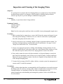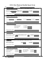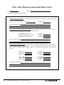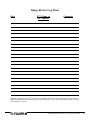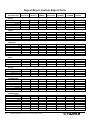
1
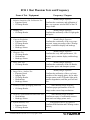
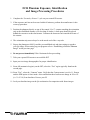
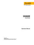
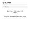
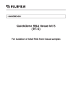
FUJIFILM Medical Systems
FCR Quality Assurance Program
Introduction
This manual consists of three sections. Section I describes the Fuji FCR 1 Shot Phantom and the
various tests that can be performed using the phantom. Section II features good practice tips and
maintenance guides for your CR image reader and associated components of your imaging system. Section III contains the forms needed to thoroughly document your Quality Assurance
Program. Do not write in this book, photocopy the pertinent forms in Section I (Establishing a
Baseline Phantom Image) and Section III.
The Fuji FCR 1 Shot Phantom provides a system wide quality analysis by incorporating eight
performance tests in a single exposure. In addition to a practical analysis of the FCR Reader, the
test tool provides an image that can be used system wide to evaluate monitor workstation and
laser printer performance.
Consistency in the performance of Quality Control testing is a must. We recommend that prior to
conducting the monthly phantom exposure, hard copy printers are calibrated according to the
manufacturers specifications. We also recommend that one individual is designated as the
Quality Assurance Leader. Other individuals should be trained to perform testing in the leader’s
absence. When an error has been detected, repeat the test to confirm that the error has not been
caused by a procedural mistake. It is important to establish the baseline FCR 1 Shot Phantom
image when you are confident that your exposure unit, CR image reader*, workstation and
image printing systems are in proper calibration.
This program was developed by the Imaging Specialist Group at FUJIFILM Medical Systems,
U.S.A., INC. Update and editing was done by Denise M. Minnigh and David W. MacCutcheon.
The information contained herein can change without notice owing to product and/or technical
improvements. Please make sure before using the product that the information you are referring
to is up-to-date.
We assume no responsibility for any consequence resulting from any wrong or improper use or
operation, etc. of the product.
© Copyright 2000 by FUJIFILM Medical Systems, U.S.A., INC.
All rights reserved. Only the Baseline Phantom Image Chart and Quality Assurance Documentation
Forms in Section III may be reproduced and copied. All other sections of this program may not be
reproduced, stored in a retrieval system, or transmitted in any form or by any means, electronic or
mechanical, including photocopying and recording, without written permission from the publisher.
*All FCR Readers are calibrated to an S# of 200 when the IP is exposed to an 80kVp beam at a distance of 72”
resulting in an exposure of 1mR at the IP surface. Fuji does not recommend the use of added filtration in the beam
beyond that used in the units normal operation. FCR Reader calibration procedures can be reviewed in the Reader
Service Manual or contact your Fuji Service Engineer or Imaging Specialist for assistance.
FUJIFILM Medical Systems U.S.A. Copyright © 2000
Table of Contents
SECTION I
FCR 1 Shot Phantom QA Program
1. FCR 1 Shot Phantom Tests and Frequency . . . . . . . . . . . . . . . . . . . . . . . . . . . . 6
2. FCR 1 Shot Phantom Diagram . . . . . . . . . . . . . . . . . . . . . . . . . . . . . . . . . . . . . 7
3. Establishing a Baseline Phantom Image . . . . . . . . . . . . . . . . . . . . . . . . . . . . . . 8
4. FCR Phantom Exposure, Identification and Image Processing Procedures . . . . . 9
FCR 1 Shot Phantom Tests
5. Relative “S” Number Calibration . . . . . . . . . . . . . . . . . . . . . . . . . . . . . . . . 10-11
6. Shading Correction . . . . . . . . . . . . . . . . . . . . . . . . . . . . . . . . . . . . . . . . . . . . . 12
7. Contrast Evaluation . . . . . . . . . . . . . . . . . . . . . . . . . . . . . . . . . . . . . . . . . . . . . 13
8. Sharpness . . . . . . . . . . . . . . . . . . . . . . . . . . . . . . . . . . . . . . . . . . . . . . . . . . . . 14
9. Laser Jitter . . . . . . . . . . . . . . . . . . . . . . . . . . . . . . . . . . . . . . . . . . . . . . . . . . . 15
10. Image Noise and Artifact . . . . . . . . . . . . . . . . . . . . . . . . . . . . . . . . . . . . . . . . . 16
11. Primary Erasure Function . . . . . . . . . . . . . . . . . . . . . . . . . . . . . . . . . . . . . . . . 17
12. Accuracy of Measurement Tools . . . . . . . . . . . . . . . . . . . . . . . . . . . . . . . . . . . 18
13. System Linearity . . . . . . . . . . . . . . . . . . . . . . . . . . . . . . . . . . . . . . . . . . . . 19-20
SECTION II
Quality Control and Good Practice Program
1.
2.
3.
4.
Quality Commitment Program Overview . . . . . . . . . . . . . . . . . . . . . . . . . . . . . 23
Review Image Quality . . . . . . . . . . . . . . . . . . . . . . . . . . . . . . . . . . . . . . . . . . . 24
Erase Unused Imaging Plates . . . . . . . . . . . . . . . . . . . . . . . . . . . . . . . . . . . . . 25
Check Image Printer . . . . . . . . . . . . . . . . . . . . . . . . . . . . . . . . . . . . . . . . . . . . 26
FUJIFILM Medical Systems U.S.A. Copyright © 2000
3
5. Review “S” Number and “L” Value . . . . . . . . . . . . . . . . . . . . . . . . . . . . . . . . . 27
6. Inspection and Cleaning of Imaging Plates . . . . . . . . . . . . . . . . . . . . . . . . 28-29
7. Inspection and Cleaning of Cassettes . . . . . . . . . . . . . . . . . . . . . . . . . . . . . . . . 30
8. Check CR Reader Functions . . . . . . . . . . . . . . . . . . . . . . . . . . . . . . . . . . . . . . 31
9. Clean CR Reader Air Vents and Work Area . . . . . . . . . . . . . . . . . . . . . . . . . . . 32
10. Workstation Monitor Check . . . . . . . . . . . . . . . . . . . . . . . . . . . . . . . . . . . . . . . 33
11. Repeat/ Reject Analysis . . . . . . . . . . . . . . . . . . . . . . . . . . . . . . . . . . . . . . . . . . 34
12. Image Consultation/ Training . . . . . . . . . . . . . . . . . . . . . . . . . . . . . . . . . . . . . 35
13. Preventative Maintenance of CR Reader . . . . . . . . . . . . . . . . . . . . . . . . . . . . . 36
SECTION III
Quality Assurance Documentation Forms
1. FCR 1 Shot Phantom Monthly Report Form . . . . . . . . . . . . . . . . . . . . . . . . . . 39
2. FCR 1 Shot Phantom Semi-annual Report Form . . . . . . . . . . . . . . . . . . . . . . . 40
3. Image Review Log Sheet . . . . . . . . . . . . . . . . . . . . . . . . . . . . . . . . . . . . . . . . 41
4. IP Maintenance Log . . . . . . . . . . . . . . . . . . . . . . . . . . . . . . . . . . . . . . . . . . . . 42
5. Workstation Monitor Checklist . . . . . . . . . . . . . . . . . . . . . . . . . . . . . . . . . . . . 43
6. Repeat/Reject Analysis Report Form . . . . . . . . . . . . . . . . . . . . . . . . . . . . . . . . 44
4
FUJIFILM Medical Systems U.S.A. Copyright © 2000
Section I - FCR 1 Shot Phantom QA Program
FCR 1 Shot Phantom Tests and Frequency
Name of Test / Equipment
6
Frequency / Purpose
1. Relative Sensitivity (S#) Calibration Test
• Exposure Room
• CR Image Reader
Monthly/Single Exposure
Confirms the consistency and calibration of
the x-ray exposure unit and PMT of the CR
image reader.
2. Shading Test
• CR Image Reader
Monthly/Single Exposure
Confirms the uniformity of the CR light guide
and optics.
3. Contrast Evaluation
• Exposure Room
• CR Image Reader
• Workstations
• Hardcopy Printer
Monthly/Single Exposure
Confirms the consistency of the x-ray exposure unit, image processing of the CR image
reader, workstation display and hardcopy
printer.
4. Sharpness Test
• CR Image Reader
• Workstations
• Hardcopy Printer
Monthly/Single Exposure
Confirms the x-ray tubes performance, CR
Reader optics, monitor display and hardcopy
printer.
5. Laser Jitter Test
• CR Image Reader
Monthly/Single Exposure
Confirms the consistency of the CR Reader,
laser printer optics and transport systems.
6. Image Noise / Artifact Test
• Exposure Room
• Imaging Plate
• CR Image Reader
• Workstations
• Hardcopy Printer
Monthly/Single Exposure
Confirms the uniformity of the x-ray beam,
condition of the imaging plates, dirt or other
foreign matter on the CR Reader light guide,
monitor degradation, and film processor artifact.
7. Primary Erasure of Imaging Plate Test
• CR Image Reader
Semi-annually/Single Exposure
Confirms proper performance of the CR
image reader erasure lamp mechanism.
8. Accuracy of Measurement Tools/Scale Test
• Workstations
• Hardcopy Printer
Semi-annually/Single Exposure
Confirms accuracy of workstation measurement tools and image printer scale.
9. System Linearity Test
• Exposure Room
• CR Image Reader
Semi-annually/Series of Exposures
Confirms EDR function and CR image reader
linearity
FUJIFILM Medical Systems U.S.A. Copyright © 2000
F
A
B1
0
.1
B2
M
M
Pb
0
.6
N
o.
6
2
D
D
LP
/M
17 "
M
C
EL
EC
ER
14 "
A: Laser Jitter (Test Object 1.6mm Pb)
B1: Contrast Patch (Outer Circle 0.15mm Pb,
Inner Circle, 0.5mm Pb)
B2: Contrast Patch (Outer Circular hole
0.0mm cu, Inner Circle 0.7mm.cu)
D: 10 cm points for Workstation & Printer
(8 total) Scale Accuracy. (Size 0.5 mm
Diameter & Depth)
EL (left), EC (center), ER (right):
Measuring Points for Shading Correction
& Sensitivity (19mm Diameter, 3.0mm
Lucite removed)
C: Sharpness Test Tool
F:
Cassette Positioning Locator Anode End
(does not appear on image)
FUJIFILM Medical Systems U.S.A. Copyright © 2000
7
Establishing a Baseline Phantom Image
Choose an x-ray room for phantom exposure that produces consistent exposures, has a good
choice of small mA stations and can create a non-grid exposure at a distance of 60 inches or
more (cassette can be placed on the floor). Newer generation x-ray equipment with digital kVp
settings may produce more accurate and repeatable exposure settings from month to month. It is
important to qualify a second x-ray room, if available, to compare test results that may have
been caused by an exposure related malfunction of the primary x-ray room.
Move the x-ray tube to a location away from the table and raise it to its maximum height so the
beam would strike the floor. Turn on the field light. Place a lead apron on the floor and in the
field. Place the designated CR IP and cassette on the apron with the green stripe at the anode
end of the x-ray tube. Place the FCR 1 Shot Phantom directly on the cassette with its identification stripe at the green stripe end. Collimate the x-ray beam to a size 1” larger than the outside
frame of the cassette.
Set the kVp at 80 and make an exposure on a small mA station (100 mA or less). Select a time
of 0.10 second. Expose and process according to steps 5-12 of the “FCR Phantom Exposure
Identification and Image Processing Procedures” located on the next page. If needed, first
adjust the mA station, then the time setting to establish an exposure with an “S” number close
to 200 (150-250). Remember as exposure decreases “S” number increases. Record the settings
in pencil on the chart below. Use the lower box to record the “back-up exposure room” exposure factors.
Primary Exposure Room Baseline Exposure Factors
Exposure Room
kVp
mA
Target “S” Number
CR Reader
Distance
IP#
Time
Phantom Serial #
Back-up Exposure Room Baseline Exposure Factors
Exposure Room
kVp
mA
Target “S” Number
CR Reader
8
Distance
IP#
Time
Phantom Serial #
FUJIFILM Medical Systems U.S.A. Copyright © 2000
FCR Phantom Exposure, Identification
and Image Processing Procedures
1. Complete the “Secondary Erasure” cycle on your control IP/cassette.
2. If the exposure unit has not been used within 90 minutes, perform the manufacturer’s tube
warm up procedure.
3. Position the phantom directly on top of the control 14 x 17 cassette matching the orientation
strip at the established distance of no less than 60 inches. A lead apron should be placed
behind the cassette to reduce backscatter. Collimate the beam one-inch outside the frame of
the cassette.
4. The orientation strip must always be at the anode end of the x-ray tube.
5. Expose the phantom at 80 kVp and the pre-established mA and time settings to produce
your QA image. When setting up your program refer to “Establishing a Baseline Phantom
Image” on the previous page.
6. Do not process immediately! Wait 10 minutes before proceeding.
7. Take your exposed IP/cassette to an available IDT.
8. Input your test image demographics for proper identification.
9. From AR (anatomical region), on the IDT, select the “Test” region typically found on the
second page.
10. From “Test”, select the “Contrast” menu. Verify that the Contrast menu is set for 1:1 Format
and the EDR option is Semi mode. Also confirm that there has been no change in SS or CS
(i.e.* 1.0/*1.0) from baselines. Process your IP.
11. Lock your baseline image on the QA workstation for comparison with future images.
FUJIFILM Medical Systems U.S.A. Copyright © 2000
9
Relative “S” Number Calibration
Objective:
Compare the “S” number to the standard. This test will evaluate the exposure system,
the calibration of the PMT (Photomultiplier tube) and the baseline density of hard copy
printer devices when an IP is exposed to the pre-established dose. The image produced
from this single exposure will be used for all the phantom evaluation monthly tests.
Frequency:
Monthly, and following service to the Light Guide or PMT of the CR Reader.
Equipment Needed:
• FCR QA 1 Shot Phantom
• Lead Apron
• Timer
• Densitometer
• Monthly Report Form
Procedure:
Note: This test should be performed in the confirmed, primary x-ray exposure room
according to the baseline exposure conditions established in the “FCR Phantom
Exposure, Identification and Image Processing Procedure” section of the manual.
Remember, the “S” number is an indication of the amount of exposure reaching the IP,
the exposure conditions and settings must be identical each month.
1. Erase the QA designated IP using the secondary erasure mode of your CR image
reader.
2. Expose and process the IP as described in the “FCR Phantom Exposure, Identification
and Image Processing Procedure” conditions section of this manual.
3. Record and evaluate the “S” number produced on the Monthly Report Form.
4. Measure the optical density produced within the center measurement circle, (EC on
the FCR 1 Shot Phantom diagram) and record the results on the Monthly Report
Form.
Precautions:
Some printers such as the Fuji Thermal Dry Imager FM-DP2636 and FM-DP 3543,
require a special optical filter to be installed in X-Rite model 301, 301RS and 331 densitometers. Filter kits are available from FMSU. Contact your Fuji Account Manager for
information. This added filter does not affect density measurements on other film types.
Check with your printer manufacturer if a compensation filter is
needed.
10
FUJIFILM Medical Systems U.S.A. Copyright © 2000
Performance and Corrective Action:
“S” Number Evaluation:
“S” variation should be no greater than +/- 20% of the established standard. If
your results exceed this level, the following steps should be taken to further
investigate.
1. Repeat the test. If results change, you may have an intermittent exposure
problem in the x-ray generator.
2. If results are still beyond tolerance, expose the phantom in the second
qualified room to confirm if the error exists in the CR Reader or the exposure
room. Call appropriate service as needed.
Hardcopy Evaluation:
When printing hard copy images, always be sure that the laser printer is freshly
calibrated and in control and that the image processing parameters are
unchanged from the baseline exam.
Compare results against the previously established baseline optical density of the
phantom image. Variation should not be greater than + 0.15 optical density (OD).
If a greater difference exists, recalibrate the printer and reprint the image. If the
“S” number is in the normal range and printer density is still outside the limits,
printer service may be needed.
FUJIFILM Medical Systems U.S.A. Copyright © 2000
11
Shading Correction
Objective:
The shading correction of the CR Reader ensures that the scanning laser intensity is uniform across the scanning width of the imaging plate.
Frequency:
Monthly, and following service to the light guide, or optics of the CR Reader.
Equipment Needed:
• FCR 1 Shot Phantom image
• Densitometer
• Monthly Report Form
Procedure:
1. Use the image produced in the “Relative “S” Number Calibration” test and proceed
to Step 3, or erase the QA designated IP using the secondary erasure mode of your
CR Image Reader to produce a new image.
2. Expose and process your standard phantom images described in the “FCR Phantom
Exposure, Identification and Image Processing Procedure” section of this manual.
3. Measure the optical density of the center circle (EC) located in the lower third of the
phantom. Record the measured density on the Monthly Report Form.
4. Measure the optical density of the circles to the left (EL) and right (ER) of center.
Record the results on the Monthly Report Form.
Precautions:
Be sure that the phantom is positioned properly as described in steps 3 and 4 of the
“FCR Phantom Exposure, Identification and Image Processing Procedures”. The purpose of these steps are to minimize the “heel effect” of the x-ray tube. Prior to servicing
the CR Reader, check the calibration and shading correction of hard copy devices to
eliminate the possibility of a printer problem.
Some printers such as the Fuji Thermal Dry Imager FM-DP 2636 and FM-DP 3543
require a special optical filter to be installed in X-Rite model densitometers. Filter kits
are available from FMSU. Contact your Fuji Account Manager for information. This
added filter does not affect density measurements on other film types. Check with your
printer manufacturer if a compensation filter is needed.
Performance and Correction Action:
The measured optical density of either outside circle should not exceed +10% of the
center optical density measurement. If your measurement exceeds this limit, re-expose
the phantom making sure that the density variation is not caused by beam collimation. If
the measured result is still out of specification and uniformity of the hard copy printer
confirmed, call service as needed.
12
FUJIFILM Medical Systems U.S.A. Copyright © 2000
Contrast Evaluation
Objective:
To confirm that the contrast of CR image is normal when compared to an established
standard. This procedure can be performed on printed images, the QA workstation and
clinical review workstations.
Frequency:
Monthly, after CR Reader Service or as needed.
Equipment Needed:
• Baseline FCR QA 1 Shot Phantom image
• Current FCR QA 1 Shot Phantom image
• Monthly Report Form
Procedure:
1. Use the image produced in the “Relative “S” Number Calibration” test and proceed
to Step 3, or erase the QA designated IP using the secondary erasure mode of your
CR image reader to produce a new image.
2. Expose and process the IP as described in the “FCR Phantom Exposure, Identification
and Image Processing Procedure” section of this manual.
3. Visually compare the contrast patches against the established baseline.
Precautions:
When comparing hard copy images always be sure that the laser printer is freshly calibrated and in control. When comparing softcopy images monitor brightness and contrast
controls should be checked for display consistency and viewing room lighting set to its
minimum level.
As monitor brightness degrades, a loss of visibility of the contrast difference within each
patch group will occur. It is up to each facility to determine the application and useful
life of viewing monitors.
Note: At an 80-kVp non-grid exposure, it is not uncommon for a slight scatter (density)
pattern to occur in the phantom image around the perimeter of the darkest density patch.
Performance and Corrective Action:
The contrast patches should demonstrate two distinct densities each and be similar in
relationship to the baseline image. Typically, a simple pass/fail observation is sufficient,
however, measurements on a printed film can be recorded and tracked as a density difference.
FUJIFILM Medical Systems U.S.A. Copyright © 2000
13
Sharpness
Objective:
To confirm optic and image processing systems are functioning normally.
Frequency:
Monthly, or after service to the CR Reader.
Equipment Needed:
• FCR QA 1 Shot Phantom image
• 2X magnifier
• Monthly Report Form
Procedure:
1. Use the image produced in the “Relative “S” Number Calibration” test and proceed
to Step 3, or erase the QA designated IP using the secondary erasure mode of your
CR image reader to produce a new image.
2. Expose and process your standard phantom image as described in the “FCR Phantom
Exposure Identification and Image Processing Procedures” section of this manual.
3. Inspect the resolution test tool located in the center of the phantom.
Precautions:
Be sure to always expose the Fuji FCR 1 Shot Phantom using the small focal spot and at
the proper distance.
Note: The copper filter within CR 1 Shot Phantom produces a significant amount of
scatter radiation and degrades the visibility of detail in the line pair test tool. This evaluation is a comparative study from month to month and is not meant to demonstrate maximum system resolution. System resolution is measured as described in the Acceptance
Test Section of the Service Manual of your CR Reader.
Performance and Corrective Action:
FCR Readers are available in standard and HQ models. Compare the results of your latest exposure to the standard “baseline” image. Record the results of your evaluation on
the Monthly Report Form.
The resolution target can be viewed on hard copy or on a review station monitor. Use a
magnifier to help evaluate resolution on a printed film. Soft copy presentation may limit
the visible resolution of the CR image. Use the magnification function on the workstation if available.
Note: When reviewing the resolution test tool on “soft copy” a wavy artifact (moiré pattern) may occur. This is a normal event caused by interference between the frequency of
the test tool and display device. If your workstation has a magnification tool, changing
magnification levels will help to reduce or eliminate this interference.
14
FUJIFILM Medical Systems U.S.A. Copyright © 2000
Laser Jitter
Objective:
To confirm the mechanical consistency and accuracy of the laser optics module and
transport systems of the CR Reader and the laser printer.
Frequency:
Monthly, after service to the CR Reader Optics, or as needed.
Equipment Needed:
• FCR QA 1 Shot Phantom image
• 2X magnifier
• Monthly Report Form
Procedure:
1. Use the image produced in the “Relative “S” Number Calibration” test and proceed
to Step 3, or erase the QA designated IP using the secondary erasure mode of your
FCR Image Reader to produce a new image.
2. Expose and process the IP as described in the “FCR Phantom Exposure, Identification
and Image Processing Procedures” conditions section of this manual.
3. Inspect the horizontal and vertical edges of the “T” object in the phantom image.
Performance and Corrective Action:
At the QA workstation, inspect the high contrast edges of the “T” object, located in the
center of the upper one third of the phantom image. Look for jagged edges or loss of
continuity. If jagged edges exist on the workstation and printed image, call for service
on the CR Reader. If jagged edges occur on the printed image but are not visible on the
QA workstation, call for service of the laser printer. Record the results of your evaluation on the Monthly Report Form.
Note: It is normal for the “T” object to demonstrate some level of “jagged edges” under
magnification, however, they should not be visible to the unaided eye. Compare the
most recent image against the baseline image to establish any change using 2X magnification.
FUJIFILM Medical Systems U.S.A. Copyright © 2000
15
Image Noise and Artifact
Objective:
Review the phantom image for the presence of elevated noise or artifact. This evaluation
can be used to inspect images from the IP, CR Reader and hardcopy printer.
Frequency:
Monthly, as part of normal phantom evaluation, or as needed.
Procedure:
1. Use the image produced in the “Relative “S” Number Calibration” test and proceed to
Step 3, or erase the QA designated IP using the secondary erasure mode of your CR
image reader to produce a new image.
2. Expose and process the IP as described in the “FCR Phantom Exposure, Identification
and Image Processing Procedures” section of this manual.
3. After checking the “S” number to ensure it is in normal range, compare the new image
against the standard baseline image.
Performance and Corrective Action:
Inspect the image for signs of increased graininess or artifact.
Increased Graininess:
Increased image grain is typically related to exposure. Check exposure factors,
collimation, distance and “S” number.
Imaging Plate:
Dust, stains and scratches on the IP will produce white artifacts on the image. IP’s should
be dusted with a soft, dry, lint free cloth on a monthly basis. Particles that cannot be
removed in this manner should be removed by gently cleaning the IP with Anhydrous
Ethanol. *
CR Reader:
Reader artifacts can be caused by dust or dirt particles on the Light Guide. This will typically be demonstrated as a soft edged white line running end to end in the image area of
the film parallel to the 14” or 10” dimension. Call service to clean the Light Guide.
Hardcopy Printer:
Artifacts that are present on the hardcopy but not visible on the QA workstation are usually caused by the printer, and may require service assistance. These artifacts may be
caused by laser optics, dirty print heads, rollers, chemical stains; or improper film storage, loading or handling.
* Anhydrous Ethanol is a federally controlled HAZMAT and is stocked in most hospital laboratories or
pharmacies. If an outside supplier is needed, small quantities (less than 5 gallons per year) can be purchased from:
Pharmco Products, Inc.
Phone: (203) 740-3471
(specify Denatured Alcohol SDA3A 200 Proof)
16
FUJIFILM Medical Systems U.S.A. Copyright © 2000
Primary Erasure Function
Objective:
To confirm that the primary erase function of the CR Reader is capable of fully erasing
an exposed CR imaging plate.
Frequency:
Semi-Annually, following service to the erasure lamp module, or when erasure failure is
suspected.
Equipment Needed:
• FCR 1 Shot Phantom
• Semi Annual Report Form
Procedure:
1. Use the imaging plate returned from the “Relative “S” Number Calibration” test and
proceed to Step 3, or erase the QA designated IP using the secondary erasure mode of
your CR image reader and produce a new phantom image.
2. Expose and process the IP as described in the “FCR Phantom Exposure Identification
and Image Process Procedures” of this manual.
3. After the IP is returned to the cassette, bring the IP and cassette to the IDT for re-processing. If you are testing CR Readers with an internal stacker, request the return of
the same IP using the utility maintenance mode (see the specific CR Reader’s
Operations Manual).
4. Reprocess the previously returned IP using the standard Contrast Test menu and
verify output image to laser printer and/or connected workstation.
Performance and Corrective Action:
The image produced from the second scanning of the original phantom IP should be
completely blank. There should be no evidence of residual exposure on the re-processed
IP. If residual image is demonstrated, recheck that the original phantom image “S” number is within 200 + 15%. If “S” number is within normal range and a residual image
exists, have service check the erasure lamp section of the CR Reader.
FUJIFILM Medical Systems U.S.A. Copyright © 2000
17
Accuracy of Measurement Tools
Objective:
To evaluate workstation and laser printer measurement tool accuracy.
Frequency:
Semiannually, or following software upgrade to the workstation or printer.
Equipment Needed:
• Workstation measurement tools (if available)
• Printed FCR 1 Shot Phantom image
• Pencil and paper
• Semi Annual Report Form
Procedure:
Workstation:
If your QA or diagnostic review workstation offers the feature of a measurement tool,
activate the measurement function. Look closely within the object area of the phantom. There are a series of tiny holes drilled at 10-cm intervals in the upper q of the
phantom. Carefully place the cursor over the measurement hole and activate measurement function. Check the tool accuracy at 10 and 20-cm points on the horizontal and
vertical axis.
Printed image:
Printed images may be presented in reduced or enlarged size. If your laser printer
produces a measurement scale printed along the outside of the image, place a piece of
paper in the center of the scale and mark the paper at 10-cm intervals using a fine
point pencil. Compare the distance between the phantom points on the printed CR 1
Shot phantom image and the paper scale produced from that image.
Performance and Corrective Action:
Measurement tools on the workstation or printed on the film should be accurate to within + 5%. For example, a 10-cm measurement on the film or workstation should yield a
measured result of 9.5 to 10.5cm or 19-cm to 21-cm over a 20-cm distance.
Note: The scale from the CR Reader may not appear or may be out of the above recommended tolerances on some brands of printers or network print server systems. Scale
errors caused by other manufactures devices are beyond our control. Check with your
printer or network print server manufacturer for additional information.
18
FUJIFILM Medical Systems U.S.A. Copyright © 2000
System Linearity
Objective:
To confirm that the EDR (Exposure Data Recognizer) will re-scale under and over exposure
and produce images of consistent density when the phantom is exposed to normal, 50% less
and 100% more exposure.
Frequency:
Semi-annually.
Equipment Needed:
• FCR 1 Shot CR Phantom
• Densitometer
• Stop Watch
• Semi Annual Report Form
Procedure:
1. Erase the QA designated IP using the secondary erasure mode of your CR image reader.
2. Set up the exposure room for your normal phantom exposure except reduce the exposure
time to one-half (50%) of the original setting. Do not change kVp distance or mA
settings.
3. Expose the phantom, wait 10 minutes, and process the phantom image as described in the
“FCR Phantom Exposure, Identification and Image Processing Procedures” section of the
manual.
4. Using the Semi-annual Report Form record the “S” number and optical density of the center circle in the lower third of the phantom on the lines designated Image 1 S# and OD.
5. Using the same IP and cassette, repeat steps 3 and 4, except expose the phantom two
times before processing and record the “S” number and optical density measurement on
the lines designated Image 2 S# and OD.
6. Once more using the same IP and cassette, repeat steps 3 and 4 except expose the phantom four times before processing and record the “S” number and optical density measurement on the lines designated Image 3 S# and OD.
Precautions:
Multiple exposures should be conducted at 5 to 10 second intervals between exposures. Wait
10 minutes between the final exposure of any series and the processing of the IP.
Most experts agree that the exposure timer circuit of the generator is more stable than mA
station or kVp selection. Do not perform this test by changing mA stations. If errors are
detected, it is important to qualify the accuracy and repeatability of the x-ray exposure unit.
System Linearity continued on next page
FUJIFILM Medical Systems U.S.A. Copyright © 2000
19
Performance and Corrective Action:
Using the “S” number and optical density of Image 2 as a baseline, compare the images
produced at one half and double dose.
“S” Number Evaluation:
As exposure increases “S” number decreases. The “S” number of Image 1 should be
double (+15%) that of Image 2.
The “S” number of Image 3 should be one half (+15%) that of Image 2.
Density Evaluation:
Measure the optical density of the center circle located in the lower third of
Image 2. Compare the optical density of the same location of Image 1 and
Image 3. The optical density of Images 1 and 3 should be within + 15% of
Image 2.
Example:
“S” number of Image 2 = 186
Target “S” number for Image 1 is 372 (2X Image 2 “S” number).
+15% = 55.8 for an acceptance range of 316.2 to 427.8
Target “S” number for Image 3 is 93 (1/2 Image 2 “S” number).
+15% = 13.95 for an acceptance range of 79.05 to 106.95
Optical density of Image 2 = 1.45
Target optical density for Image 1 and 3 should be the same.
+15% = 0.22 for a range of 1.23 to 1.67.
20
FUJIFILM Medical Systems U.S.A. Copyright © 2000
Section II - Quality Control and Good Practice Program
Quality Commitment Program Overview
A complete Quality Assurance Program consists of quality control testing and Good Practice.
Many important quality control tests are performed with the FCR 1 Shot Phantom. However,
independent testing and maintenance of additional system components, such as printers and
workstations, are also very important. This portion of the manual concentrates on quality assurance aspects that are not a function of the FCR 1 Shot Phantom.
Good Practice can be defined as a plan for proper usage, daily maintenance and housekeeping,
and should be practiced by all operators. A program promoting Good Practice helps to focus all
operators into a quality system.
Section II is designed to be a basic guide for Fuji Computed Radiography systems and the
peripheral components that make up the full imaging chain at your facility. Consult the manufacturers of the various components involved for their recommendations on quality control, recommended maintenance schedules and Good Practice.
This portion of the Quality Commitment program is divided into five timed sequences: Every
Image, Daily, Monthly, Quarterly, and Semi-Annual.
Every Image
1. Review image quality
Daily
1. Erase imaging plates
2. Check image printer
Monthly
1. Review “S” numbers and “L” values
2. Inspection and cleaning of imaging plates
3. Inspection and cleaning cassettes
4. Check CR Reader functions.
5. Cleaning of CR Reader air vents and work area
6. Workstation Monitor Check
Quarterly
1. Repeat/Reject Analysis
Semi-annual
1. Image Consultation and Training (Imaging Specialist).
2. Preventative maintenance of CR Reader (Service Engineer).
FUJIFILM Medical Systems U.S.A. Copyright © 2000
23
Review Image Quality
Objective:
Monitoring image quality and confirming patient identification helps to reduce repeats. It
is good practice to review the images as they are acquired.
Frequency:
Review patient images as they are acquired.
Equipment Needed:
• Patient images (soft and/or hardcopy)
• Image Review Log Sheet
Procedure:
1. Review each patient image, and verify that the proper menu was selected.
2. Confirm that the correct patient demographics were used.
3. Check “S” number and “L” values are in the appropriate range for good image quality.
4. If contrast or densities are inconsistent, validate calibration of the “Hardcopy” output
device.
5. Record repeated images on the Repeat/Reject Analysis form.
6. Report image quality issues, such as image noise or a perceivable change in image
contrast or density to the person(s) involved in quality assurance for investigation.
Performance and Corrective Action:
Using the acceptable “S” number and “L” value range, the proper menu selection and
patient demographics are important for optimizing patient image quality. If repetitive
errors are found in these areas, additional operator training should be conducted to
improve these deficiencies.
Reference:
• Precautions for Exposure, Appendix Z in the Fuji Operations Manual
• Troubleshooting Guide, pages 26-31 in the Fuji Medical Systems, CR User’s Guide
• CR System Speed, page 10, in the Fuji Medical Systems, CR User’s Guide
24
FUJIFILM Medical Systems U.S.A. Copyright © 2000
Erase Unused Imaging Plates
Objective:
The imaging plates used in CR are sensitive to radiation from many sources including
scatter and background radiation. Imaging plates unused for extended times can produce
images of lower image quality (decreased contrast and higher noise). For this reason, it is
good practice to erase IP’s at least every 48 hours if they have not been used.
Frequency:
Daily, or IP’s that have not been used within 48 hours.
Equipment Needed:
CR Reader
Department IP’s in Cassettes
Procedure:
1. At the CR Reader select “Secondary Erasure” for any IP that may have been exposed to
scatter radiation or may not have been used in the past 24 hours. To erase a direct x-ray
exposure select “Primary Erasure”.
2. Insert cassette into the CR Reader.
3. Once erasure is complete, remove cassette from CR Reader and return it to routine use.
4. CR Reader will return to routine processing upon completion of each erasure process.
Performance and Corrective Action:
Any energy absorbed by the IP will remain trapped until the erasure process has been completed. Ambient radiation can increase mottle within the image, lower contrast and affect
“S” value reading. IP’s that are suspect of being exposed to scatter or direct x-ray exposure
should be erased prior to use.
IP’s should be stored away from both direct and in-direct radiation. To reduce the effects of
ambient radiation on IP’s, it is recommend that they are stored on edge and off the floor.
Cassettes should be rotated first-in, first-out.
Only the cassette used for the exposure should be in the x-ray room. It is poor practice to
leave exposed or unexposed cassettes in the x-ray room during a procedure.
Reference:
• Operations, Chapter 2 in the Fuji Operation Manual
• Erasure of IP’s, page in the Fuji Medical Systems, CR User’s Guide
• Technical Tips, page 6 in the Fuji Medical Systems, CR User’s Guide
FUJIFILM Medical Systems U.S.A. Copyright © 2000
25
Check Image Printer
Objective:
It is good practice to confirm that all printers are producing images of proper density and
contrast and are free of artifacts.
Frequency:
Daily, at the beginning of the workday.
Equipment Needed:
Calibration film from integrated printer sensitometer
Densitometer (internal or external)
Procedure:
1. Review image printers “Operation” and “Service Manual” for checking density and
calibration procedures.
2. Calibrate the printer each time film is loaded or as directed in the manufacturer’s manual.
3. Verify that fluid levels, temperature and chemical activity of wet processing systems are
within acceptable limits.
4. Inspect images as they are acquired for artifacts. If artifacts exist, investigate the source
and call service as needed.
5. If wet processors are used, conduct a Hypo Retention test quarterly for film archival.
Precautions:
Film is produced in batches. Consequently, there may be slight variations in the characteristics of the film between batches. In addition, film aging and storage conditions can also
affect the sensitometric characteristics of the film. Calibrate the printer each time film is
loaded or as directed in the manufacturer’s manual.
Some printers such as the Fuji Thermal Dry Imager FM-DP 2636 and FM-DP 3543, require
a special optical filter to be installed in X-Rite model 301, 301RS and 331 densitometers.
Filter kits are available from FUJIFILM Medical Systems. Contact your Fuji Account
Manager for information. This added filter does not affect density measurements on other
film types. Check with your printer manufacturer if a compensation filter is needed.
Performance and Corrective Action:
If problems are detected, corrective action should be taken before clinical films are
processed under less than optimal conditions. If density steps fall outside control limits, follow the printer manufactures recommendations for proper adjustments or recalibration.
Reference:
Image Printer Operations and Service Manuals
26
FUJIFILM Medical Systems U.S.A. Copyright © 2000
Review “S” Number and “L” Value
Objective:
To look for trends or exams where exposure factors may need to be optimized. It is good
practice to review the “S” numbers and “L” values as images are acquired and search for
trends on a monthly basis. The patient lists on workstations such as the Fuji QA-WS 771
can be sorted by selecting “S” number in ascending and descending order.
Frequency:
On a monthly basis, review “S” numbers and “L” values on patient images.
Equipment Needed:
Patient images (soft and/or hardcopy)
Image Review Log Sheet
Procedure:
1. The “S” (Sensitivity) number and the “L” (Latitude) value is presented with the output
image. The “S” number, though not an absolute value, can be used to help determine if
optimal exposure settings were used to obtain clinically acceptable images. A review of
the “S” numbers and “L” values can be done as the images are acquired.
2. Any trend indicating that exposures are greater than necessary should be investigated.
Digital imaging systems, such as CR, will maintain proper density as dose is reduced. As
dose is reduced, noise increases. Exposure values should be established at the lowest
level that produces images of low noise and good image quality. Each clinical facility is
responsible for setting their own “S” number criteria.
3. The “L” value can be used to determine if the appropriate portion of the recorded exposure was used to form the output image. Typically, “L” values range from 1.7 to 2.3.
Only extreme variations will warrant further investigation. This will be manifested in
either very high or very low contrast images and typically represents images that are the
result of grid cut-off, improper positioning or exposure.
Performance and Corrective Action:
It is the responsibility of each facility to establish exposure ranges that employ the lowest
dose based on image quality desired per examination. The cause of abnormally high or low
“S” numbers and “L” values should be determined and corrective action should be taken to
improve these values that effect image quality.
Reference:
• CR System Speed, page 10, in the Fuji Medical Systems, CR User’s Guide
• Information on “S” Numbers pages 11-12, in the Fuji Medical Systems, CR User’s
Guide
• Acceptable Exposure Range for Fuji CR Imaging Plates, pages 13-15 in the Fuji Medical
Systems, CR User’s Guide
FUJIFILM Medical Systems U.S.A. Copyright © 2000
27
Inspection and Cleaning of the Imaging Plates
Objective:
It is good practice to inspect and clean Imaging Plates on a regular basis to help eliminate
unwanted image artifacts. Any damage to the IP should be identified and preventative
measures put in place to prevent damage to additional imaging plates.
Frequency:
Monthly, or upon observation of image artifacts.
Equipment Needed:
Cleaning solution
Lint-free cloth
Cotton glove
Note: Lint free cotton gloves and lens cloth are available in most photographic supply stores.
Procedure:
1. While wearing lint free cotton gloves, remove the IP from the cassette and inspect for artifacts and physical damage. If artifacts exist, use a lint free cloth such as a photographic
lens cloth, and gently rub the surface clean.
2. It may be necessary to use a cleaning solution if stains or persistent artifacts remain. Use
only those cleaning solutions recommended by the IP manufacturer. See page 16 titled
“Image Noise and Artifact Test”, for more details.
3. Always wear appropriate protective clothing when handling cleaning solutions. Do not
apply the solution directly to the plate, rather, put a small amount of the solution on a lint
free cloth and wipe the surface of the IP in a zigzag pattern to remove the artifact.
4. If any artifact cannot be removed by these methods, or if physical damage is noted, the
plate should be immediately removed from service and the Quality Control technologist
informed. It may be helpful to contact a Fuji Service Engineer to help identify the cause
of the damaged imaging plates.
5. To ensure the best usage of the IP’s within a facility, a rotation system for management of
cassettes and IP’s should be instituted.
Precautions:
Using a solution other than those recommended by the IP manufacturer can result in irreparable damage and will void any warranty either written or implied. Due to the nature of many
cleaning solutions, it is important to follow the safety recommendations of the
solution manufacturer when handling and storing these products. Refer to the MSDS sheet
for each solution.
28
FUJIFILM Medical Systems U.S.A. Copyright © 2000
Performance and Corrective Action:
Review images on a routine bases for white spots (minus density artifacts) that may be
caused by dust or dirt particles.
Reference:
• IP Handling, Appendix B in the Fuji Operation Manual
• Routine Maintenance, page 34 in the Fuji Medical Systems, CR User’s Guide
• Cleaning Solution for Imaging Plates ST-V/HR-V Generation and Higher, page 35 in
the Fuji Medical Systems, CR User’s Guide
• CR Imaging Plate and Cassette Warranty Policy, page 36 in the Fuji Medical
Systems, CR User’s Guide
• Fuji Cares About the Environment, pages 37-38 in the Fuji Medical Systems, CR
User’s Guide
FUJIFILM Medical Systems U.S.A. Copyright © 2000
29
Inspection and Cleaning of Cassettes
Objective:
It is good practice to determine if there is any physical damage to the CR cassette.
Identify the cause of the problem and remove any damaged cassette from use. Insertion
of a broken cassette into a CR Reader can result in mechanical failure and system shutdown.
Frequency:
Monthly, or upon observation of a damaged cassette.
Equipment Needed:
Soft lint-free cloth
Mild cleaning solution
Procedure:
1. Visually inspect the CR cassette. The inspection should include the removal of the IP
(see Inspection and Cleaning of Imaging Plates). Any cassette showing physical damage should be removed from service immediately and repaired. If the cassette cannot
be repaired to a state that is acceptable for use, it should be replaced.
2. Clean CR cassettes with a cleaning solution typically used for cleaning the exterior of
film/screen radiographic cassettes. Blood or other body fluids should be cleaned with
the appropriate germicidal agent. Always remove the IP before cleaning the interior
surfaces of the cassette. DO NOT immerse the cassette when cleaning. Apply the
cleaning solution to a soft cloth sparingly. Always wear the appropriate protective
clothing when handling any cleaning solution. Allow the cassette to fully air dry
before reinserting the IP.
Performance and Corrective Action:
Cassettes that exhibit any damage should be removed from use and repaired or replaced.
Reference:
• IP Handling, Appendix B in the Fuji Operation Manual
• Routine Maintenance, page 34 in the Fuji Medical Systems, CR User’s Guide
• Cleaning Solution for Imaging Plates ST-V/HR-V Generation and Higher, page 35 in
the Fuji Medical Systems, CR User’s Guide
• CR Imaging Plate and Cassette Warranty Policy, page 36 in the Fuji Medical
Systems, CR User’s Guide
• Fuji Cares About the Environment, pages 37-38 in the Fuji Medical Systems, CR
User’s Guide
30
FUJIFILM Medical Systems U.S.A. Copyright © 2000
Check CR Reader Functions
Objective:
It is good practice to confirm that the CR Reader and its attached devices are functioning properly and that indicator lamps operate normally.
Frequency:
Monthly, or after any service or maintenance on the CR Reader.
Equipment Needed:
Checklist
Procedure:
1. Each clinical site using CR will have an individual set up and configuration. Begin by
making a list of system components and the functions that should be checked on a
monthly basis. It is good practice to include the checklist in your monthly QC
records.
2. Verify that each function is working and note that the function has been checked. If
any equipment does not perform as expected, contact the appropriate service organization to investigate the problem.
Example:
FCR Reader
1. Erase IP
2. Urgent processing
3. Date/ Time
4. HIC, LP, and IDT connections
ID Terminal
1. Barcode Reader
2. Options Buttons
3. Service Options
4. Date/ Time
Performance and Corrective Action:
Each of the items on the CR Reader function checklist should pass or receive a check
mark. Items not passing the checklist should be reported immediately. Malfunctioning
equipment should be reported to service engineer for repair or replacement as soon as
possible.
Reference:
• Operations, Chapter 2 in the Fuji Operation Manual
• Reader Specific Information, Section II, pages A-O in the Fuji Medical Systems, CR
User’s Guide
FUJIFILM Medical Systems U.S.A. Copyright © 2000
31
Clean CR Reader Air Vents and Work Area
Objective:
It is good practice to keep the intake air vents of the CR Reader, hardcopy device and
workstations free from lint and other obstructions to reduce dust artifact and ensure
proper cooling and operation.
Frequency:
Monthly
Equipment Needed:
Soft cloth
Mild cleaning solution
Vacuum
Procedure:
1. Use a soft cloth dampened with a mild cleaning solution suitable for plastic and metal
surfaces and wipe the surface areas on and around the CR Reader and other
components.
2. Wipe all work surfaces, cassette storage areas, and especially the cassette insertion
area of the CR Reader. Dampen the cloth with the cleaning fluid. Never apply
solutions directly to any of the components.
3. Following the directions on the label, an Industrial CRT cleaner can be used for the
monitors and IDT’s.
4. It may be necessary to use a vacuum to remove lint within the vent covers.
Performance and Corrective Action:
The possibility of dust artifacts appearing the patient images should be reduced as cleanliness is improved. Keeping air vents clear and filters clean will ensure proper cooling
of the equipment.
Reference:
CR Reader Operations and Service Manuals
32
FUJIFILM Medical Systems U.S.A. Copyright © 2000
Workstation Monitor Check
Objective:
It is good practice to assess the general image display of softcopy monitors used for QA
or Diagnostic Workstations.
Frequency:
Monthly
Equipment Needed:
SMPTE test pattern and/or
Phantom Image
Procedure:
1. Clean the monitor with an industrial CRT cleaning solution following the directions on
the label.
2. Lower the lights in the reading room to their lowest acceptable level.
3. This test can be performed with the Phantom image and/or a SMPTE test pattern.
While the “Contrast Test” in this manual can produce a helpful contrast patch pattern,
it is the product of x-ray exposure and therefore not always repeatable. Many QA
workstations are loaded with the SMPTE test pattern. It is good practice to confirm
that the 0%-5% and the 95%-100% patches and horizontal and vertical resolution patterns are visualized as they were during your baseline evaluation.
Performance and Corrective Action:
If there is a detectable change in performance since the baseline evaluation, image quality
may be compromised. A calibration procedure for the monitor may need to be performed
by a qualified service person.
Reference:
Workstation Monitor Operations and Service Manuals
FUJIFILM Medical Systems U.S.A. Copyright © 2000
33
Repeat/Reject Analysis
Objective:
It is good practice to determine the number and cause of repeated images. This data can
be used to help reduce patient exposure, improve image quality and department efficiency. Employ the same basic procedure as for film/screen imaging.
Frequency:
Quarterly or as needed.
Equipment Needed:
All reject films/images or reject list from Review Image Quality test
Total number of films/images produced during test period
All repeated images during the analysis period
Procedure:
1. On a quarterly basis, start collecting rejected hardcopy images. For softcopy review
systems, create a log of repeated images.
2. Calculate the repeat rate by comparing total image acquisition to those repeated.
Evaluate each image for the reason it was repeated and categorize based on previous
experience with film/screen imaging. New categories may be added, such as
“Improper Menu Selection”. With CR it will be important to determine if an additional exposure was actually made, as it is often possible to correct images at the workstation.
Performance and Corrective Action:
The repeat rate should be below 5%. A repeat category that is significantly higher than
others indicates an area for potential improvement. Identifying the common cause of
repeats can be used to determine if additional training or review is needed. Use the
information obtained between the Review Image Quality and Review “S” Number and
“L” Value together with the Repeat and Reject analysis test to search for areas of
improvement. Programs such as the Fuji Certified Trainer or Advanced Image
Processing help facilities maximize the benefits of Computed Radiography.
34
FUJIFILM Medical Systems U.S.A. Copyright © 2000
Image Consultation/Training
Objective:
Department turnover often requires scheduled revisits by Fuji Imaging Specialist.
Schedule imaging specialist consultations for “Image Optimization” or on-site
“Educational Seminars” to maintain a consistent level of technical expertise in your
department.
Frequency:
Semi-annual, or when turnover in radiology personnel requires.
Procedure:
It is good practice to maintain on-going image consultation or training programs with
your Fuji Imaging Specialist. Image Optimization reviews imaging and exposure procedures and promotes improved efficiency through custom menu creation to meet each
facility’s specific needs. In addition, one and two day on-site educational seminars are
available. These seminars include “The FCR Certified Trainer Program”, “Advanced
Image Processing” and “FCR Quality Assurance”. Contact your Fuji Account Manager
or Imaging Specialist for details.
Performance and Corrective Action:
On-going educational seminars are essential for maintaining image quality.
FUJIFILM Medical Systems U.S.A. Copyright © 2000
35
Preventative Maintenance of CR Reader
Objective:
It is good practice to follow the Preventative Maintenance (PM) schedule set up by the
manufacturer of your CR system. Routine scheduled Preventative Maintenance assures
that your system is accurately calibrated and operating properly.
Frequency:
Semi-annually
Procedure:
The scheduled Preventative Maintenance, performed by a Fuji Service Engineer covers
all operating systems of the CR Reader. Routine scheduled service on your FCR system
ensures calibration, cleaning and adjustment of the laser optics, light guide and transport
systems.
Performance and Corrective Action:
On-going Preventative Maintenance is essential for maintaining image quality. Quality
Assurance procedures and good practice methods that uncover a potential problem
should be reported to the appropriate service organization for repair or replacement.
36
FUJIFILM Medical Systems U.S.A. Copyright © 2000
Section III - Quality Assurance Documentation Forms
FCR 1 Shot Phantom Monthly Report Form
Date
Operator
1. RELATIVE SENSITIVITY TEST Action Limit: S# +/- 20% of baseline Density +/- 0.15 OD baseline
Baseline S#
Baseline density
Monthly Test S#
Monthly density
Acceptable?
Acceptable?
Notes/ Corrective Action
2. SHADING CORRECTION TEST Action Limit: Measured density of outside circles should not exceed
+/- 10% of the center circle)
L Circle
C Circle
R Circle
Acceptable?
Notes/ Corrective Action
3. CONTRAST EVALUATION Action Limit: Contrast patch visibility compared to baseline image.
CR QA Workstation
Other Workstation
Printed Image
Acceptable?
Acceptable?
Acceptable?
Notes/Corrective Action
4. SHARPNESS TEST Action Limit: No change from baseline image.
Baseline Sharpness monitor
Baseline Sharpness printer
Monthly Sharpness monitor
Monthly Sharpness printer
Acceptable?
Acceptable?
Notes/Corrective Action
5. JITTER TEST Action Limit: No Jitter [ jagged edges ] visible around T object.
Jitter on monitor Image
Jitter on printer Image
yes/no
yes/no
Acceptable?
Acceptable?
Notes/Corrective Action
6. IMAGE NOISE AND ARTIFACT Action Limit: Noise similar to baseline image, Artifact free.
Noise
Artifact
FCR QA workstation
Acceptable?
QA Workstation
Acceptable?
Other workstation
Acceptable?
Other Workstation
Acceptable?
Image Printer
Acceptable?
Image Printer
Acceptable?
Notes/Corrective Action
FUJIFILM Medical Systems U.S.A. Copyright © 2000
39
FCR 1 Shot Phantom Semi-Annual Report Form
Date
Operator
Perform the Standard Monthly Tests Plus:
1.
PRIMARY ERASURE TEST
Action Limits: No evidence of previous image on returned imaging plate.
Evidence of previous image (Yes/No)
Acceptable?
Notes/ Corrective Action
2.
ACCURACY OF MEASUREMENT TOOLS Action Limits: No more than +/- 5% error [ 9.5- 10.5
cm on 10 cm measurement. 19-21 cm on a 20 cm. Measurement].
QA Workstation Accuracy
Diagnostic Workstation Accuracy
Image Printer Scale Accuracy
Acceptable?
Acceptable?
Acceptable?
Notes/ Corrective Action
3.
EXPOSURE LINEARITY TEST Action Limits: S# of image 1 should be double [+/- 15%] that of
image 2. S# of image 3 should be one half [+/- 15%] that of image 2. Optical density of center measurement circle (EC) of images 1 and 3 should be within +/- 15% of image 2 (see example in test instruction
section).
Image 1 S#
Image 2 S#
Image 3 S#
Acceptable?
Acceptable?
Acceptable?
Image 1 OD
Image 2 OD
Image 3 OD
Acceptable?
Acceptable?
Acceptable?
Notes/ Corrective Action
40
FUJIFILM Medical Systems U.S.A. Copyright © 2000
Image Review Log Sheet
Date
PT’S Name or
I.D. Number
Comments
Note: Any images that need to be reviewed by a Fuji Imaging Specialist should be placed on this log. Include any
additional information such as technique, grid or positioning issues. A copy of this log should be placed in all areas
where images are reviewed.
FUJIFILM Medical Systems U.S.A. Copyright © 2000
41
IP Maintenance Log
Cleaning and Inspection Records
42
Date of
Installation
Size
FUJIFILM Medical Systems U.S.A. Copyright © 2000
A
ug
Se
p
O
ct
N
ov
D
ec
IP
Number
Ja
n
Fe
b
M
ar
A
pr
M
ay
Ju
n
Ju
l
YEAR
Quarterly Comments
Workstation Monitor Checklist
Cleaning and Inspection Records
MONTH
Monitor
Number
YEAR
Date of
Installation
SMPTE or Phantom Test Results
Additional Comments
FUJIFILM Medical Systems U.S.A. Copyright © 2000
43
Repeat/Reject Analysis Report Form
EXAMINATION
POSITION
MOTION
TECH.
ERROR
SKULL:
Skull
Facial Bones
Mastoids
Sinuses
Other
CHEST:
Lungs
Ribs
Scapula
Sternum
Other
ABDOMEN:
ABD.
BE
GI
GB
KUB
IVP
Other
SPINE:
C-Spine
T-Spine
L-Spine
Other
PELVIS:
Pelvis
Hip
Sacrum, Coccyx
Other
UPPER
EXTREMITIES:
Hand/Fingers
Wrist
Forearm
Elbow
Humerus
Shoulder
Other
LOWER
EXTREMITIES:
Foot/Toes
Ankle
Leg
Knee
Femur
OTHER:
44
FUJIFILM Medical Systems U.S.A. Copyright © 2000
MENU
SELECTION
HIGH “S”
NUMBER
LOW “S”
NUMBER
OTHER
FUJI Medical Systems U.S.A., Inc
419 West Avenue Stamford, CT 06902
(203) 324-2000
www.fujimed.com