1
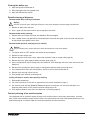
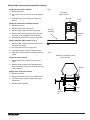
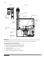
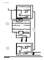
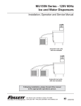
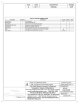
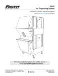
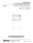
EU155N Series - 230V, 50 Hz
Ice and Water Dispensers
Installation, Operation and Service Manual
Automatic load units with one ice machine
Automatic load units with one ice machine
Following installation, please forward this manual
to the appropriate operations person.
801 Church Lane • Easton, PA 18040, USA
Toll free (877) 612-5086 • +1 (610) 252-7301
www.follettice.com
Order parts online:
www.follettice.com
00120303R02
EU155N Ice and Water Dispensers
2
Contents
Welcome to Follett. . . . . . . . . . . . . . . . . . . . . . . . . . . . . . . . . . . . . . . . . . . . . . . . . . . . . . . . . . . . . . . . . . . . . . . . . . . . . . 4
Before you begin. . . . . . . . . . . . . . . . . . . . . . . . . . . . . . . . . . . . . . . . . . . . . . . . . . . . . . . . . . . . . . . . . . . . . . . . . . . . . 4
Important Safety Information . . . . . . . . . . . . . . . . . . . . . . . . . . . . . . . . . . . . . . . . . . . . . . . . . . . . . . . . . . . . . . . . . . . . . 4
Specifications . . . . . . . . . . . . . . . . . . . . . . . . . . . . . . . . . . . . . . . . . . . . . . . . . . . . . . . . . . . . . . . . . . . . . . . . . . . . . . . . . 5
Electrical requirements . . . . . . . . . . . . . . . . . . . . . . . . . . . . . . . . . . . . . . . . . . . . . . . . . . . . . . . . . . . . . . . . . . . . . . . . 5
Plumbing . . . . . . . . . . . . . . . . . . . . . . . . . . . . . . . . . . . . . . . . . . . . . . . . . . . . . . . . . . . . . . . . . . . . . . . . . . . . . . . . . . . 5
Clearance and access information . . . . . . . . . . . . . . . . . . . . . . . . . . . . . . . . . . . . . . . . . . . . . . . . . . . . . . . . . . . . . . . 5
Field wiring diagrams . . . . . . . . . . . . . . . . . . . . . . . . . . . . . . . . . . . . . . . . . . . . . . . . . . . . . . . . . . . . . . . . . . . . . . . . . 6
Installation . . . . . . . . . . . . . . . . . . . . . . . . . . . . . . . . . . . . . . . . . . . . . . . . . . . . . . . . . . . . . . . . . . . . . . . . . . . . . . . . . . . . 7
Installing EU155N dispenser in counter . . . . . . . . . . . . . . . . . . . . . . . . . . . . . . . . . . . . . . . . . . . . . . . . . . . . . . . . . . . 7
Installing remote ice machine (automatic load units only) . . . . . . . . . . . . . . . . . . . . . . . . . . . . . . . . . . . . . . . . . . . . 8
To start up and operate dispenser . . . . . . . . . . . . . . . . . . . . . . . . . . . . . . . . . . . . . . . . . . . . . . . . . . . . . . . . . . . . . . . . 9
User information . . . . . . . . . . . . . . . . . . . . . . . . . . . . . . . . . . . . . . . . . . . . . . . . . . . . . . . . . . . . . . . . . . . . . . . . . . . . . . . 9
How the dispenser works . . . . . . . . . . . . . . . . . . . . . . . . . . . . . . . . . . . . . . . . . . . . . . . . . . . . . . . . . . . . . . . . . . . . . . 9
Cleaning and sanitizing procedures . . . . . . . . . . . . . . . . . . . . . . . . . . . . . . . . . . . . . . . . . . . . . . . . . . . . . . . . . . . . . . . 9
Cleaning bin before use . . . . . . . . . . . . . . . . . . . . . . . . . . . . . . . . . . . . . . . . . . . . . . . . . . . . . . . . . . . . . . . . . . . . . . 10
Periodic cleaning of dispenser . . . . . . . . . . . . . . . . . . . . . . . . . . . . . . . . . . . . . . . . . . . . . . . . . . . . . . . . . . . . . . . . . 10
Quarterly cleaning of ice machine system . . . . . . . . . . . . . . . . . . . . . . . . . . . . . . . . . . . . . . . . . . . . . . . . . . . . . . . . 10
Disassembly instructions for periodic cleaning . . . . . . . . . . . . . . . . . . . . . . . . . . . . . . . . . . . . . . . . . . . . . . . . . . . . 11
Service . . . . . . . . . . . . . . . . . . . . . . . . . . . . . . . . . . . . . . . . . . . . . . . . . . . . . . . . . . . . . . . . . . . . . . . . . . . . . . . . . . . . . . 12
Dispense wheel motor removal (Fig. 3) . . . . . . . . . . . . . . . . . . . . . . . . . . . . . . . . . . . . . . . . . . . . . . . . . . . . . . . . . . 12
Before calling for service . . . . . . . . . . . . . . . . . . . . . . . . . . . . . . . . . . . . . . . . . . . . . . . . . . . . . . . . . . . . . . . . . . . . . 14
Dispenser troubleshooting guide . . . . . . . . . . . . . . . . . . . . . . . . . . . . . . . . . . . . . . . . . . . . . . . . . . . . . . . . . . . . . . . 14
Replacement parts . . . . . . . . . . . . . . . . . . . . . . . . . . . . . . . . . . . . . . . . . . . . . . . . . . . . . . . . . . . . . . . . . . . . . . . . . . . . 15
Dispenser exterior. . . . . . . . . . . . . . . . . . . . . . . . . . . . . . . . . . . . . . . . . . . . . . . . . . . . . . . . . . . . . . . . . . . . . . . . . . . 15
Dispense assembly – side view . . . . . . . . . . . . . . . . . . . . . . . . . . . . . . . . . . . . . . . . . . . . . . . . . . . . . . . . . . . . . . . . 16
Hopper – side view . . . . . . . . . . . . . . . . . . . . . . . . . . . . . . . . . . . . . . . . . . . . . . . . . . . . . . . . . . . . . . . . . . . . . . . . . . 17
Auger motor . . . . . . . . . . . . . . . . . . . . . . . . . . . . . . . . . . . . . . . . . . . . . . . . . . . . . . . . . . . . . . . . . . . . . . . . . . . . . . . 18
Electrical components . . . . . . . . . . . . . . . . . . . . . . . . . . . . . . . . . . . . . . . . . . . . . . . . . . . . . . . . . . . . . . . . . . . . . . . 19
EU155N Ice and Water Dispensers
3
Welcome to Follett ––––––––––––––––––––––––––––––––––––––––––––––––––
Follett ice and water dispensers enjoy a well-deserved reputation for excellent performance, long-term reliability and
outstanding after-the-sale support. To ensure that this dispenser delivers that same degree of service, we ask that
you take a moment to review this manual before beginning the installation of the dispenser. Should you have any
questions or require technical help at any point, please call our technical service group at (610) 252-7301.
Before you begin
§ After uncrating and removing all packing material, inspect the equipment for concealed shipping damage. If
damage is found, notify the shipper immediately and contact Follett Corporation so that we can help in the
filing of a claim, if necessary.
§ Check your paperwork to determine which model you have. Follett model numbers are designed to provide
information about the type and capacity of Follett ice dispensing equipment. Following is an explanation of
the different model numbers in the U155 Series.
EU155NR400AR
Ice dispense chute location – R = right side, L = left side
Condenser type – A = air-cooled, W = water-cooled
Remote ice machine(s) capacity and refrigerant – 400 = 400 lbs (181kg)/day, R404A
800 = 800 lbs (363kg)/day, R404A
absence of = manual fill unit
N = ice and water only, no beverage rail or valves
Approximate storage capacity in lbs
Dispenser configuration – U = undercounter
Alternate voltage – C = 230V 50Hz
Important Safety Information –––––––––––––––––––––––––––––––––––––––––
Please read and adhere to the following safety information while installing, using, or servicing your Follett 7 Series
Ice Dispenser.
1. Always disconnect power before servicing the dispenser.
2. Ice is slippery. Maintain counters and floors around dispenser in a clean and ice-free condition.
3. Ice is food. Follow the recommended cleaning and sanitizing instructions to maintain cleanliness of delivered
ice.
4. Follett manual load dispensers can accommodate most cube/cubelet ices up to 1" square, or Follett
compressed nugget ice. Crushed, flake, bagged, nugget or congealed ice cannot be used. Use of these ices
can jam dispenser and void warranty. Separate any “waffle-like” sections of cubes before adding to dispenser.
For ice compatibility questions, please call Follett customer service at (877) 612-5086 or +1 (610) 252-7301.
5. Follett recommends use of an activated carbon filter for units equipped with ice machines.
6. Storage area of dispenser contains mechanical, moving parts. Keep hands and arms clear of this area at all
times. If access to this area is required, power to unit must be disconnected first.
EU155N Ice and Water Dispensers
4
Specifications –––––––––––––––––––––––––––––––––––––––––––––––––––––
Electrical requirements
§ Each ice machine and dispenser requires separate circuit with electrical disconnect within 6m. Equipment
ground required.
§ 230V, 50 Hz, 2A
Plumbing
Dispenser
§ 3/4" PVC slip joint for hopper drain
§ 3/4" PVC pipe nipple for beverage drain pan
§ 3/8" ID red line tubing for water in
§ Drains should be hard piped and insulated. Maintain at least 6 mm per 304 mm (1/4" per 12 in.)run slope on
drain line run
Ice machine
§ Refer to Ice machine Installation Manual packed with ice machine for installation instructions
Clearance and access information
§ 1296mm above counter
§ 305mm on side opposite tower, below counter
§ Counter front or rear panel must be removable for service access to both sides of dispenser and ice
machine(s), if any
§ Below counter access to drain clean-out required on utility side of dispenser
§ See Ice machine Installation Manual packed with ice machine(s) for clearance requirements for automatic
load dispensers
Side view
Front view
696mm
305mm
305mm
553mm
1264mm
153mm min
712mm
water connection
432mm
hopper drain
beverage
pan drain
661mm
480mm min
480mm min
305mm min
794mm
Automatic load units with 1 ice machine
Automatic load units with 2 ice machine
EU155N Ice and Water Dispensers
5
Field wiring diagrams
Automatic load units
One 230V, 50 Hz circuit is required. The field wiring diagram is intended to aid the elelectrician or technician in
understanding how the equipment works.
Electric supply
230V 50Hz
Electric supply
230V 50Hz
EU155N
Dispenser
ER400A/W
ice machine
GND
L2
L1
Junction box
GND
Electric supply
230V 50Hz
L2
optional second
ER400A/W
L1
Junction box
GND
L2
L1
Connections to complete
Junction box
EU155N Ice and Water Dispensers
6
Installation ––––––––––––––––––––––––––––––––––––––––––––––––––––––––
Installing EU155N dispenser in counter
!
1.
All EU155N dispensers must be installed level in both directions and supported from below with 153
– 229mm adjustable legs provided, or channels installed on site. DO not hang dispenser on flange of
counter.
Check that dispenser location meets all requirements in this manual and cut counter as shown.
2. Block up area below counter cut-out to support dispenser when lowered into place.
3. For automatic load dispensers, disconnect ice transport tube from bracket in storage area of dispenser. (Since
this tube must be reinstalled in bracket after dispenser is dropped into counter, note how tube is held by bracket
tabs before disconnecting.)
4. Carefully lower dispenser into counter until it rests on support blocks.
5. Adjust height from below with standard leg kit until dispenser flange rests flush with counter.
6. Apply a bead of NSF listed silicone sealant (Dow-Corning RTV-732 or equivalent) approximately 6mm in
diameter around perimeter of dispenser where it meets counter and smooth sealant to a 4mm radius.
7.
!
Install a hard drain line, maintaining at least a 6mm per 304mm run slope, and insulate line to prevent
PVC pipe is suggested. Care must be taken in sweating any metal drain pipe used. Excessive heat
applied while sweating metal pipe may melt plastic fitting on dispenser. condensation.
8. Make electrical connections in accordance with applicable wiring diagrams provided, as well as NEC and local
codes. Provide disconnects within 3m of dispenser and ice machine for servicing.
Counter cut-out
(772mm) +3mm
- 3mm
(667mm)
+3mm
- 3mm
Front of counter
EU155N Ice and Water Dispensers
7
Installing remote ice machine
!
(automatic load units only) ––––––––––––––––––––––––––––––
Correct installation of remote ice machine(s) is critical to proper performance of ice machine
and dispenser.
Check to make sure bin signal on ice machine control board is switched to 24 V connection.
Refer to installation manual packed with ice machine for important details on ice transport
tube run, ventilation requirements and other installation requirements. Failure to comply with
instructions will void warranty.
1.
Position ice machine in desired location.
2. Push one end of ice transport tube(s) through hole(s) provided in side of dispenser.
3. Route tube into ice tube bracket inside dispenser and engage bracket tabs in holes located in end of ice
transport tube(s). (See drawings below.)
4. Proceed with ice transport tube installation from dispenser to ice machine in compliance with instructions
contained in ice machine installation manual packed with ice machine.
Ice tube retainer bracket
ice tube
thermostat
thermostat
Front view
Tabs in ice tube
retainer bracket
engage holes in ice
tube and hold tube
in place
25mm
ice tube
Side view
EU155N Ice and Water Dispensers
8
To start up and operate dispenser ––––––––––––––––––––––––––––––––––––
1.
Follow detailed cleaning instructions in service manual before operating dispenser.
2. For manual load units, remove front drain pan or rear lid and fill storage area with compatible ice.
!
Follett manual load dispensers can accommodate most cube/cubelet ices up to 26mm square and
Follett compressed nugget ice. Crushed, flake, nugget, bagged or congealed ice cannot be used. Use
of these ices can jam dispenser and void warranty. Separate any “waffle-like” sections of cubes before
adding to dispenser. For questions about ice compatibility, call Follett's customer service group at (610)
252-7301.
3. Turn power switch located on control box to “ON” position.
4. For automatic fill units, follow detailed instructions in ice machine installation section of installation manual, then
turn ice machine (bin signal) switch(es) located on control box to “ON” position and begin to make ice.
5. When dispenser has at least 153mm of ice in storage area, press “PUSH FOR ICE” lever or button to ensure
that dispenser is operating properly. Note: If additional start-up information is needed, call Follett Corporation at
+1 (610) 252-7301.
User information –––––––––––––––––––––––––––––––––––––––––––––––––––
How the dispenser works
Follett's EU155N Series ice and water dispensers are available in manual load configurations (using ice from
another source) or automatic load configurations, fed from one or two Follett 400 lb (181kg)/day remote ice
machines.
In all models, ice is stored below the counter in the dispenser storage area. When the dispense lever or button is
pushed, the dispense motor is activated. This causes the wheel assembly in the storage area to turn, moving ice to
the vertical auger assembly, which carries ice up to the dispense chute where it drops by gravity into the container.
In automatic load units, ice is manufactured in either one or two Follett remote ice machines. These ice machines
may be located up to 6m away from the dispenser. As water freezes to the inside walls of the ice machine
evaporator, a rotating stainless steel auger removes ice and carries it to the top of the evaporator assembly where it
is compressed and extruded through an outlet port. The extruded ice is then pushed through the tube to the storage
compartment of the dispenser. A level fill circuit maximizes fill in the storage area by rotating the wheel at intervals
until the bin is completely filled. When the bin is filled, a bin stat shuts the ice machine off to avoid overfilling of the
bin. The ice machine will restart after 20 minutes if the bin is calling for ice.
Cleaning and sanitizing procedures –––––––––––––––––––––––––––––––––––
!
Warning!
Always disconnect power before cleaning dispenser.
Using solutions below, clean and sanitize storage area and beverage lines before starting up unit and on a routine
basis as noted below.
Solution A:
Prepare a cleaning solution (200 ppm of available chlorine content) of chlorinated detergent. Cleaning
solution temperature must be at 75˚ – 125˚F (24˚ to 52˚C).
Solution B:
Prepare a sanitizing solution (50 ppm of available chlorine content) of chlorinated detergent.
Sanitizing solution temperature must be at 75˚ – 125˚F (24˚ to 52˚C).
EU155N Ice and Water Dispensers
9
Cleaning bin before use
1.
Wipe storage area with Solution A.
2. Rinse thoroughly with clear, potable water.
3. Wipe with Solution B to sanitize.
Periodic cleaning of dispenser
Recommended daily cleaning of drain pan
!
1.
Notice!
DO NOT run plastic parts (drain pan, dispense chute cover, dispense wheel) through a dishwasher.
Remove all debris from drain pan.
2. Pour 1 gallon (4L) hot water into drain pan to keep drain lines clear.
Recommended weekly cleaning
1.
Remove drain pan and grill and wash with Solution A. Rinse thoroughly.
2. Pour a solution of one cup (8oz/237ml) household bleach mixed with one gallon (3.8L) hot water into drain pan
to help prevent algae growth in drain lines.
Recommended quarterly cleaning (every 3 months)
!
1.
Notice!
On push button units, remove dispense switch from dispense chute cover before
Turn power switch to “OFF” position and remove top from dispenser.
2. Remove ice from storage area.
3. Remove dispense chute cover, chute, auger motor assembly, auger and auger tube (page 10).
4. Remove drain pan, grille, dispense wheel and cover plate (page 11).
5. Clean all components and bin storage area with Solution A, rinse thoroughly with clear water and sanitize with
Solution B.
6. Remove clean-out plug from drain line tee on side opposite dispense tower and let bath drain.
7.
Use a bottle brush to clean coil with Solution A, then rinse and sanitize with Solution B.
8. Reinstall clean-out plug in drain line tee.
9. Pour potable water into bath to submerge coil.
Putting unit back in service after quarterly cleaning
1.
Reassemble components.
2. For manual load units, fill unit with an approved ice (see caution statement on page 1).
3. For automatic load units with R400A/W (R404A refrigerant) ice machines, turn bin signal switch(es) and
dispenser power switch to “ON” position and allow storage area to fill.
4. Push dispense button or lever to test that dispenser is functioning properly.
Quarterly cleaning of ice machine system
Units equipped with ice machines require cleaning of ice machine system at least every three months, and more
often if local water conditions dictate. Failure to clean ice machine system will result in decreased performance and
potential damage to ice machine. Refer to Ice machine Operation and Service Manual.
EU155N Ice and Water Dispensers
10
Disassembly instructions for periodic cleaning
Dispense chute cover removal
1.
Fig. 1
Remove top cover.
Front view
right-hand unit
2. Push chute cover up vertically to slip off holding
tab.
3. After clearing tab, pull chute cover forward to
remove.
top cover
chute
cover
Dispense mechanism assembly removal
1.
Remove top cover.
2. Remove chute cover (see above).
3. Remove auger motor assembly (see above).
drain pan
assembly
4. Remove quick release pins from the ice chutes
and gates, then unplug wires from solenoids.
dispense
chute
5. Lift dispense mechanism up and off auger tube.
Auger and auger tube removal (Fig. 3)
1.
Remove auger motor and dispense mechanism
assembly (see above).
2. Pull auger upward to clear auger tube.
3. Lift auger tube upward to clear dispenser top.
4. Slide tube and bearing plate through auger tube
gasket.
Dispense wheel removal
1.
Fig. 2
Dispense assembly, top view
right-hand unit
Remove drain pan assembly and bin access
cover.
2. Remove center thumbnut and threaded rod on
dispense wheel assembly and lift wheel out front
access opening.
solenoid
Auger motor assembly removal
1.
Remove top cover.
2. Remove one thumbnut on rear of motor bracket.
3. Lift motor bracket up and unplug electric quick
disconnects.
4. Remove motor assembly.
gate
quick
release
pin
ice chute
EU155N Ice and Water Dispensers
11
Fig. 3
side view
front view
auger
auger tube
dispense wheel
auger motor
(side view)
rotating
agitator
stationary
agitator
wheel
motor
auger bearing
plate
baffle
plate
wheel motor
mounting plate
Service ––––––––––––––––––––––––––––––––––––––––––––
Disassembly instructions for service requirements only – NOT required for any cleaning procedure.
Dispense wheel motor removal (Fig. 3)
1.
Remove drain pan, bin access cover and dispense wheel.
2. Remove stainless steel baffle plate under dispense wheel.
3. Remove two screws holding wheel motor bracket on bin.
4. Lift plate and motor up.
5. Unplug electric quick disconnects from motor.
6. Lift motor and mounting plate out front access opening.
EU155N Ice and Water Dispensers
12
Wiring diagrams
WATER SWITCH
C
L2
WATER SOLENOID
NO
Wht
Blk
Orn
L1
AUGER MOTOR
COUNTERCLOCKWISE ROTATION
INterlock RELAY
R3
DISPENSE RELAY
R1
Orn
BLK
4
Pur
4
7
Red
Pur
Red
Wht
Blk
M1
7
PL2-1
POWER
PL2-2
PL2-3
Blu
Blu
WHEEL
COUNTERCLOCKWISE ROTATION
AUTOFILL
R2
Red
Pur
1
Red
Blk
Wht
M2
7
PL3-2
PL3-3
AUTOFILL R2
Orn
Blu
9
6
Blk
Blu
PL3-1
Wht
220 Volts
T1
Red
Yel
24 Volts
DISPENSE SWITCH
EU155N
Right hand
dispenser
DISPENSE RELAY
Red
Brn
C
Yel
R1
NO
B
A
interlock relay
white
white
white
C
C
NO
TOP LID
SWITCH
C
NO
DRAINPAN
SWITCH
Yel
R3
NO
B
A
REAR LID
SWITCH
DISPENSE RELAY
R1
Red
Right or
left hand
dispenser
Yel
Blu
6
9
DISPENSE SOLENOID
AutoFill Timer
AUTOFILL RELAY
Red
Blu
2
3
2
18 MIN OFF
5 SEC ON
BIN
T-STAT
Brn
1
B
R2
Yel
A
Yel
3
IM_#1
SWITCH NO. 1
IM_#2
BIN SIGNAL
to
Ice Machine 2
WHITE
BLACK
WHITE
BLACK
SWITCH NO. 2
BIN SIGNAL
to
Ice Machine 1
Orn
AUGER MOTOR
CLOCKWISE ROTATION
DISPENSE RELAY
R1
Orn
Pur
4
Red
Red
Wht
Blk
M1
7
PL2-1
EU155N
Left hand
dispenser
PL2-2
Pur
Blu
Blu
PL2-3
WHEEL
CLOCKWISE ROTATION
AUTOFILL R2
Pur
1
Red
7
Red
Blk
PL3-3
AUTOFILL R2
Orn
Blu
6
9
Wht
M2
PL3-2
PL3-1
Blu
LEGEND:
TERMINAL STRIP CONNECTION
PIN and SOCKET CONNECTION
EU155N Ice and Water Dispensers
13
Before calling for service
1.
Check that there is ice in dispenser and that congealed cubes are not causing a jam.
2. Check that circuit breaker and switches are in “ON” position.
3. Check that drain pan, rear lid and top are on securely. If ajar, dispenser will not operate. When the top is off,
auger does not operate, even though the solenoids do.
4. Check that all drains are clear.
Note: For units equipped with Follett compressed nugget ice machine, see Ice machine Operation and Service
Manual for service and troubleshooting information.
Dispenser troubleshooting guide
Sympton
Possible cause
Solution
Ice does not dispense.
• Auger motor does not run
• Wheel motor does not run
1. Power switch faulty or in OFF position;
loose connection.
2. Faulty dispense switch.
3. Faulty transformer.
4. Drain pan ajar.
5. Faulty drain pan safety switch.
1. Turn power switch to ON position;
check connections.
2. Replace switch.
3. Replace transformer.
4. Check pan and reseat.
5. Replace switch.
Ice does not dispense.
• Auger motor runs
• Wheel motor runs
• Gate does not open
1. Loose electrical connection.
2. Linkage problem between solenoid and
gate.
3. Faulty solenoid.
1. Check connections.
2. Check linkage.
3. Replace solenoid.
Ice does not dispense.
• Auger motor does not run
• Wheel motor runs
1. Loose electrical connection.
2. Faulty auger motor.
3. Faulty run capacitor.
1. Check connections.
2. Check auger motor.
3. Check run capacitor.
Ice does not dispense.
• Auger motor runs
• Wheel motor does not run
1. Loose electrical connection.
2. Faulty wheel motor.
3. Faulty run capacitor.
1. Check connections.
2. Check wheel motor.
3. Check capacitor.
No ice in dispenser.
1. Power switch in OFF position or faulty.
2. Bin signal switches in OFF position or
faulty.
3. Faulty bin t-stat.
4. Faulty transformer.
5. Ice machine related problem.
6. Faulty run capacitor.
1. Check switch and replace if
necessary.
2. Check switch and replace if
necessary.
3. Replace bin t-stat.
4. Replace transformer.
5. Refer to ice machine Operation and
Service Manual for diagnosing.
6. Check for power and bin signal on
ice machine PC board.
If problems persist after following this basic troubleshooting guide, call Follett’s technical service department at
+1 (610) 252-7301.
EU155N Ice and Water Dispensers
14
Replacement parts
Dispenser exterior
Front view
right hand (RH) tower
(push button dispensing)
Top view
unit with right hand (RH) tower
8
6
17
7
9
10
2
12
5
14
1
13
3
3
15
17
4
4
11
16
Reference #
Description
Part #
1
Label, “Follett”
502438
2
Top cover (includes label and magnet)
502905
3
Drain pan (includes magnet)
502903
4
Grille, drain pan
502450
5
Cover, electrical components
502902
6
Lid, rear access (includes magnet)
502904
Not shown
Cover, ice storage (under drain pan)
502453
7
Label, ice, dispense cover, push button
502623
8
Label, water, dispense cover, push button
502617
9
Cover, dispense chute, push button operation (includes button and label), ice
502440
10
Cover, dispense chute, push button operation (includes button and label), water
502440
11
Chute, focus, clear plastic
502459
Not shown
Push pin, clear chute
502610
12
Switch, push button operation, for ice (includes label)
502441
13
Splash shield, right hand unit
502612
Not shown
Splash shield, left hand unit
502613
14
Thumbscrew, splash shield, 10-32 x 1/2
501100
Not shown
Panel, access, right hand and left hand units
502907
16
Panel, wrap, right hand unit
502909
Not shown
Panel, wrap, left hand unit
502908
Not shown
Panel, rear, motor support, right hand unit
502586
Not shown
Panel, rear, motor support, left hand unit
502587
Not shown
Clip, Tinnerman, 10-32
502621
Not shown
Screw, 10-32 x 1/2
502287
Not shown
Legs, 153mm adjustable to 229mm, set of 4
502454
17
Switch, water dispense, push button operation (includes label)
502648
Not shown
Plug 2 lead, male
502333
Not shown
Plug 2 lead, female
502334
EU155N Ice and Water Dispensers
15
Dispense assembly – side view
Dispense assembly side view
(RH unit shown)
5
3
9
top view
1
9
6
7
2
11
4
8
10
Reference #
Description
Part #
1
Gate, dispense
502455
2
Linkage pin, gate/solenoid
502456
3
Pin, quick release, 141mm, dispense gate
502102
4
Solenoid (includes linkage pin)
00120295
5
Dispense mechanism assembly, right hand unit
502458
Not shown
Dispense mechanism assembly, left hand unit
502496
6
Spring, dispense mechanism (1 per side)
501950
7
Chute, ice
502457
8
Wrap, dispense mechanism
502607
9
Bushing, Ni liners
501249
10
Screw, 8-32 x 5/16
502625
11
Pin, spring
502624
EU155N Ice and Water Dispensers
16
Hopper – side view
5
1
7
9
3
8
11
2
6
10
4
Reference #
left-hand unit shown
Description
Part #
1
Auger, LH unit (black, stamped with “1”)
502491
Not shown
Auger, RH unit (gray, stamped with “2”)
502492
2
Plate, auger bearing
501696
Not shown
Tube, auger, right hand unit
502487
Not shown
Tube, auger, left hand unit
502488
3
Wheel, dispense (includes stud and rotating agitator)
501681
4
Baffle (under dispense wheel)
501684
Not shown
Drive bar (under dispense wheel)
501682
5
Motor, vertical auger
502889
6
Motor, wheel
502890
Not shown
Seal, wheel motor
501333
Not shown
Spacer, wheel motor
501768
Not shown
Capacitor, wheel motor
502891
7
Agitator, rotating, 534mm long
502484
8
Plate, wheel motor mounting
502615
9
Agitator, stationery
502490
Not shown
Bracket, ice tube, double tube
502497
Not shown
Ice transport tube (sold by the foot)
500366
Not shown
Ice transport tube, 10 ft
502522
Not shown
Ice transport tube, 20 ft
502523
Not shown
Insulation, transport tube (sold by the foot)
501176
10
Coil, plain water
502461
11
Tubing, water (sold by the foot)
502356
Not shown
Cover, blank ice entry
502674
Not shown
Gasket, ice entry
502672
Not shown
Plate, ice entry, 2 holes
502673
EU155N Ice and Water Dispensers
17
Auger motor
top view
side view
7
6
3
10
4
6
5
9
1
8
2
11
Reference #
Description
Part #
Auger motor/drive assembly, vertical (includes all items below)
5028931
1
Motor, vertical auger (includes gearbox and capacitor)
502889
2
Chain, auger drive #35, 40p
502477
3
Sprocket 35#, 22T 5/8 bore
50247
4
Sprocket 35#, 12T 5/8 bore
502479
5
Drive shaft
502480
6
Bearing, auger, upper and lower
501314
7
Cover and bearing, chain drive (includes 501314)
502912
8
Capacitor, 25mf, 270V
502892
9
Key, Woodruff
502482
10
Washers, thrust (4)
501765
11
Mounting plate, auger motor (includes 501314)
502913
EU155N Ice and Water Dispensers
18
Electrical components
14
6
11
8
13
1
9
9
15
10
5
11
7
4 3 7
6
15
2
Reference #
Description
Part #
1
Transformer, 24V
502885
2
Relay, dispense
501826
3
Relay, auto fill
501826
4
Timer, auto fill (automatic fill units)
502471
5
Strip, terminal
502472
6
Tube, water dispense, stainless steel
502356
7
Bracket, water solenoid
502611
8
Fitting, outlet, 1/8 MPT x 3/8, compression
502562
9
Valve, solenoid, water
208103
10
Fitting, inlet, plastic, 1/4 barb
502637
11
Tubing, water (sold by the foot)
502356
13
Switches (power and ice machine)
502209
14
Bracket, switch mounting, RH (power and ice machine)
502914
Not shown
Bracket, switch mounting, LH (power and ice machine)
502906
15
Chute, focus, clear plastic
502459
Not shown
Thermostat, bin level
501432
Not shown
Magnetic switch
(1) one located under top cover
(2) two located under electrical component cover
502887
Not shown
Magnets
(2) two located on drain pan
(1) one located on top cover
(1) one located on rear cover
502888
EU155N Ice and Water Dispensers
19
SafeCLEAN and SensorSAFE are trademarks of Follett Corporation.
Chewblet and Follett are registered trademarks, and Horizon is a trademark of Follett Corporation, registered in US.
801 Church Lane • Easton, PA 18040, USA
Toll free (877) 612-5086 • +1 (610) 252-7301
www.follettice.com
®
00120303R02
03/12