1
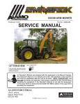
BOOM ARM MOWER
Assembly Instruction Manual
JOHN DEERE
JD-6415, JD-6420, JD-6615, JD-6715, JD-7220
JD-7320, JD-7420, JD-7520, Cab 2 WD / 4 WD
Published 02-05
Part No. 02982434
ASSEMBLY MANUAL
Tractors equipped with additional options, special equipment, tractor manufacturer modifications,
new tractor models, or Customer alterations may prevent this Mount Kit from being properly
mounted to the tractor. Alamo Group is not responsible for modifications to the MountKit to
accommodate these differences.
ALAMO INDUSTRIAL
1502 E. Walnut
Seguin, Texas 78155
210-379-1480
© 2005 Alamo Group Inc.
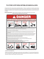
TO THE OWNER/OPERATOR/DEALER
All implements with moving parts are potentially hazardous. There is no substitute for a cautious, safe-minded
operator who recognizes the potential hazards and follows reasonable safety practices. The manufacturer has
designed this implement to be used with all its safety equipment properly attached to minimize the chance of
accidents.
BEFORE YOU START!! Read the safety messages on the implement and shown in your manual.
Observe the rules of safety and common sense!
WARRANTY INFORMATION:
Read and understand the complete Warranty Statement found in this Manual. Fill out the Warranty Registration
Form in full and return it to within 30 Days. Make certain the Serial Number of the Machine is recorded on the
Warranty Card and on the Warranty Form that you retain.
INTRODUCTION
ABOUT THIS MANUAL:
The intent of this publication to provide the competent technician with the information necessary
to perform the CORRECT Assembly to the Alamo Industrial Product. This will, in turn provide for
complete customer satisfaction
It is hoped that the information contained in this and other Manuals will provide enough detail to
eliminate the need for contact of the Alamo Industrial Technical Service Dept. However, it should be
understood that many instances may arrive where correspondence with the Manufacturer is necessary.
CONTACTING MANUFACTURER: (Please help us Help You! Before You Call! )
Alamo Industrial Service Staff Members are dedicated to helping you solve your problem, or
your customer’s service problem as quickly and efficiently as possible. Unfortunately, we receive
entirely to many calls with only a minimum amount of information. In some cases, the correspondent
has never gone out to look at the equipment and merely calls inquiring of the problems described to him
by the operator or customer.
Most calls received by Alamo Industrial Service can be classified into approx. 6 general categories.
1.
Hydraulic or Mechanical Trouble Shooting.
2.
Request for Technical Information or Specifications.
3.
Mounting or Fitting Problem.
4.
Special Service Problem.
5.
Equipment Application Problems.
6.
Tractor Problem Inquiries.
HOW YOU CAN HELP:
Make sure the call is necessary! Most of the calls received may not be necessary if the Dealer
Service Technician would do the following.
1.
Check the Service Information at your Dealership provided by Alamo Industrial, This
would include, Service Bulletins, Information Bulletins, Parts Manuals, Operators Manuals, Assembly
Manual or Service Manual, many of these are available via the Alamo Industrial Internet site (www.AlamoIndustrial.Com). Attempt to diagnose or repair problem before calling.
2.
If a call to Alamo Industrial is needed, Certain Information should be available and ready
for the Alamo Industrial Service Staff. Such information as, Machine Model, Serial Number, Your Dealer
Name, Your Account Number and Any other information that will be useful. This information is vital for
the development of a prompt and correct solution to the problem. This will also help to develop a
database of problems and related solutions, which will expedite a solution to future problems of a similar
nature.
3.
The technician may be asked to provide detailed information about the problem
including the results of any required trouble shooting techniques. If the information is not available, The
technician may be asked to get the information and call back. Most recommendations for repairs will
be based on the procedures listed in the Service Manual / Trouble Shooting Guide and Information
provided by customer.
CONTACT ALAMO INDUSTRIAL:
Alamo Industrial, 1502 E. Walnut St. Seguin TX. 78155, Technical Service Dept. PH: 830-379-1480
Maverick (John Deere 6615, 6715 Asy. Man) 02/05
© 2005 Alamo Group Inc.
Index -1
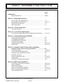
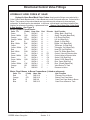
INDEX - ASSEMBLY INSTRUCTION
Page
Introduction
Manual Introduction............................................................................ Index-1
Section 1 - Model Specifications
DO NOT DO LIST (IMPORTANT)..................................................... 1-2
Maverick Boom Specifications...........................................................1-3 to 1-6
Hose Fitting Torque Chart..................................................................1-6
Bolt Torque Chart...............................................................................1-7
Section 2 - Tractor Preparation
General Information........................................................................... 2-2 to 2-8
Section 3 - Lexan Door Replacement
Consult Tractor Manufacturer Door Replacement Instructions........ 3-1 to 3-2
Section 4 - Pump & Driveshaft Installation
Pump / Driveshaft Schematic............................................................3-2
Pulley Adapter Installation.................................................................. 4-3
Install Shaft Half of Driveshaft............................................................ 4-4
Install Tank Mount Rails.................................................................... 4-5
Install Pump Mount Plate................................................................... 4-5 to 4-6
Install Pump....................................................................................... 4-6 to 4-8
Section 5 - Hydraulic Tank & Control Valve Installation
Hydraulic Tank & Valve Assembly Installation............................. 5-2
Tank Hose Routing............................................................................ 5-3 to 5-4
Control Valve Fitting Identification...................................................... 5-4 to 5-5
Hydraulic Valve Hose Referenc Sheet...............................................5-6
Head Tilt Lock Valve.......................................................................... 5-7
Valve Hose Marking Codes............................................................... 5-7 to 5-8
Diverter Valve.................................................................................... 5-7 to 5-9
Oil Cooler & Cooling Fan Assembly.................................................. 5-9
Section 6 - Main Frame Installation
Under Mount Component Information................................................ 6-2 to 6-4
Frame Installation.............................................................................. 6-5 to 6-8
Boom Rest Installation....................................................................... 6-7
Frame Counter Weight Installation.................................................... 6-8 to 6-9
Boom Turret Assembly Installation................................................... 6-9 to 6-10
Front Axle Stabilizer Kit..................................................................... 6-11
Maverick (John Deere 6615, 6715 Asy. Man) 02/05
© 2005 Alamo Group Inc.
Index -2
INDEX - ASSEMBLY INSTRUCTION
Page
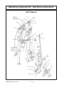
Section 7 - LH Wheel Weights
Standard Wheel Weight.................................................................... 7-2 to 7-3
Auxiliary Wheel Weight...................................................................... 7-4
Section 8 - Joystick / Wire Harness / Valve Installation
Wire Harness tractor Preparation......................................................8-2
Replace Tractor Seat Arm Rest........................................................ 8-3
"E"-Stop Switch Installation............................................................... 8-5
Joystick Installation............................................................................ 8-4 to 8-6
XS Module Installation........................................................................ 8-6 to 8-8
Interior Wire Harness Installation....................................................... 8-7 to 8-10
Exterior Wire Harness Installation..................................................... 8-11 to 8-16
Diverter Valve Harness Connections.................................................8-14 to 8-16
Oil Cooler / Fan Assembly................................................................. 8-14 to 8-16
Hydraulic Tank Mounted Sensors...................................................... 8-15 to 8-16
Cab Decals........................................................................................ 8-17
Section 9 - Boom / Head Installation
Boom Mounting.................................................................................. 9-2 to 9-5
Boom Lift Cylinder Pin Installation..................................................... 9-2 to 9-3
Boom Cylinder Schematic................................................................. 9-6
Valve Hose Schematic.......................................................................9-6
Hose Routing and Connecting........................................................... 9-2 to 9-12
Hydraulic Hose Color Identification Codes...................................... 9-8 to 9-12
Tank Hose to Boom Connections......................................................9-10 to 9-12
Tank Hose Schematic / Routing........................................................ 9-11 to 9-12
Section 10 - Fill Oil Tank / Setting Electronic Display Controls
Fill Unit with Oil...................................................................................10-2 to 10-3
Prime Pump....................................................................................... 10-3
Setting Electric Display Control Box.................................................. 10-4 to 10-11
Joystick Operation............................................................................. 10-12
front Pump & Tank Cover Installation............................................... 10-13
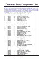
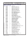
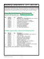
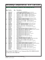
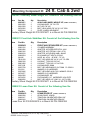
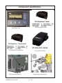
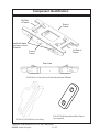
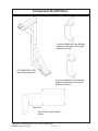
Section 11 - Mounting Specification / Component Identification
John Deere 6615 & 6715 Components Only listed
(read Component page for details)
Mount Kit Components...................................................................... 11-2 to 11-26
Component Parts Identification / Descriptions.................................. 11-2 to 11-26
Section 12 - Pre-Delivery Inspection Check List
Check List.......................................................................................... 12-2 to 12-3
Maverick (John Deere 6615, 6715 Asy. Man) 02/05
© 2005 Alamo Group Inc.
Index -3
NOTES
Maverick (John Deere 6615, 6715 Asy. Man) 02/05
© 2005 Alamo Group Inc.
Index -4
Section 1
Model
Specifications
Maverick Boom
24' & 30'
Maverick (John Deere 6615, 6715 Asy. Man) 02/05
© 2005 Alamo Group Inc.
Section 1 - 1
SPECIFICATIONS - MAVERICK
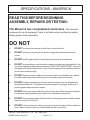
READ THIS BEFORE BEGINNING
ASSEMBLY, REPAIRS OR TESTING:
The Maverick has computerized electronics. The electronic
components can be damaged if care is not taken when performing repairs,
testing and/or during assembly.
DO NOT
1.
DO NOT short any wires across or allow them to be shorted out.
2.
DO NOT attempt to jump across any wires or supply them with alternate power
source.
3.
DO NOT install higher rated fuses than are recommended by manufacturer.
4.
DO NOT do any welding on unit unless the computer modules are unplugged first, this
is to prevent a power surge going into modules (THIS IS VERY IMPORTANT). This could
also apply to the tractor components. Check Tractors repair guide for specific instruction
about tractor model and type.
5.
DO NOT attempt to repair or adjust a component that is not intended to be repaired,
example sealed components as there are no serviceable components inside.
6.
DO NOT let anyone attempt any testing or repairs unless they are an experienced
and qualified technician. Technicians must have proper tools, gauges, meters etc. to
perform proper diagnosis and/or repairs.
7.
DO NOT perform any repairs with dirty tools or in dirty area. When working on hydraulic
components keeping system clean and free of contamination is important.
8.
DO NOT start or engage system if the oil level is not at the proper level or condition. Never
start or run unit low or out of oil.
9.
DO NOT install / add any oil unless you know it is the correct type and the container is
clean. Make certain the oil is not contaminated with dirt or any liquid.
Maverick (John Deere 6615, 6715 Asy. Man) 02/05
© 2005 Alamo Group Inc.
Section 1 - 2
SPECIFICATIONS - MAVERICK
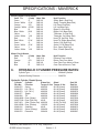
1. CUTTING CIRCUIT SPECIFICATIONS
Hyd. Pump Speed (Front Aux Pump)...................................1950 RPM
Hyd. Motor Speed.............................................................. 1220 RPM
Hyd. Motor Rated HP......................................................... 199 HP
Hyd. Motor Rotation (as viewed f/ Top of the Deck)................CW (Clockwise)
Relief Valve Setting At Motor............................................. 4000 PSI
Relief Valve Setting At Pump............................................ 4500 PSI
Hyd. Pump Flow (Front Pump @ 1950 RPM)........................25.3 GPM
Hyd. Oil Operating Temperature @ 100° F Ambient........ 155 - 165 ° F.
Hyd. Oil Filtration, (Discharge f/ Charge Pump)..................... 10 Micron
Hyd. Tank Capacity........................................................... 17-1/2 Gal.
Hyd. Motor Start Stop Time (Approximate)....................... 6 Seconds
Cutting Diameter, (Rotary Head).......................................58 Inch
Spindle............................................................................... 4.5 “ by 9” Heat Treated Alloy
Blade Bar Type.................................................................. Stacked 3 Leaf
Blade Bar Size...................................................................1-1/4” Thick X 5" Wide (Ea. Leaf)
Blade Bar Material............................................................. T1 Steel (bottom) & HRFB Steel (top & Middle)
Blade Swing.......................................................................360 Deg Swing
Blade Material.................................................................... High Carbon Alloy Steel
Cutter Weight. (Approximate w/ Rotary Head)..................950 lbs.
Cutter Deck Opening & Closing........................................ Hyd. Operated Door
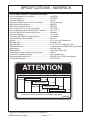
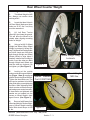
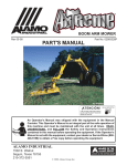
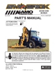
Recommended Hydraulic Oil............................................ ISO AW Hyd. Oil (See decal below)
Fluid Cleanliness level....................................................... ISO 16/14/11
ATTENTION
10°F 20°F
40°F
30°F
60°F
70°F
90°F 110°F
AW ISO VG 32
AW ISO VG 46
AW ISO VG 68
AW ISO VG 100
The correct hydraulic fluid is dependent upon ambient
temperature. Refer to chart when selecting proper grade
Maverick (John Deere 6615, 6715 Asy. Man) 02/05
© 2005 Alamo Group Inc.
Section 1 - 3
02982828
SPECIFICATIONS - MAVERICK
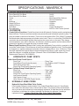
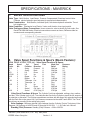
2. BOOM SPECIFICATIONS
Boom Reach 24 Foot Boom......................................................... Out 24'
Boom Reach 30 Foot Boom......................................................... Out 30'
Frame............................................................................................ Manufactured Box Sections
Pins................................................................................................Chrome Plated Alloy
Bushings........................................................................................Greasable
Weight, 24' Boom.......................................................................... 1250 lbs.
Weight, 30' Boom.......................................................................... 1450 lbs
Boom Rest.................................................................................... Tractor Axle Mounted
Boom Mounting..............................................................................ROPS or CAB Tractor Optional
3. FILTRATION
Control Valve Functions: Control functions include All Hydraulic Cylinders used to manipulate the
Maverick Boom. The boom and frame cylinders are powered by a self contained hydraulic system. The
pump is loctated on the front of the tractor. There is an in-line pressure filter (P/N 02981371) between
the closed center load sense pump and cylinder control valve. There is a return filter (P/N 02981391)
mounted to the tank that filters the fluid returning from the control valve to the tank. Filter change
recommended for every 200 to 250 hours. An electronic monitoring system monitors element back
pressure for indication of clogged filter prior to element change.
Mower Head Functions: Mower Head Functions are operated by Pump, which is mounted to the
front of the Tractor Engine. This will have an in-line Filter installed into hydraulic circuit, This filter should
be changed on a regular maintenance schedule. Filter are rated by Micron size (10 Micron), Filters
should be replaced with original Alamo Industrial Replacement Filters to make certain the correct
rated filter element is installed at all times. (Pressure Filter is P/N 02968922 and Return Filter
Replacement Element is P/N 02968923)
4.
HYDROSTATIC PUMP SPEC'S
Cutter Head Pump Circuit Spec's:
Pump Type............................................................... Piston Type
Pump Speed (Front Engine Mounted)......................Run Engine to 540 PTO Speed
Relief Setting at the Pump........................................4500 PSI
Pump Flow (Front Engine Operating Speed)...........25.3 GPM
Boom Cylinder Pump Circuit Spe'c's:
Pump Type............................................................... Piston Type
Pump Speed............................................................ 1800 RPM
Pump Flow (Front Engine Operating Speed)...........15.6 GPM
Low Pressure Standby............................................. 250 PSI
High Pressure Comp................................................3000 PSI
Horse Power at 1850 RPM (Engine Speed)............ 28.5 HP
5.
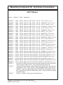
HYDRAULIC HOSE CODES
Hydraulic Hose Band Mark Color Codes:
Hose's and/or fittings are marked with a Color Coded Plastic Band around it. Some Bands
are a solid Color and some have a Colored with a Stripe. The purpose of the colored bands
are to provide a quick reference for hose and port connection. A metal band is also attachted
to the hose, on that band is an Alamo Industrial Part Number for reference if needing a
replacement hose. Always Check Hose Size, Color Code & Part Number
Maverick (John Deere 6615, 6715 Asy. Man) 02/05
© 2005 Alamo Group Inc.
Section 1 - 4
SPECIFICATIONS - MAVERICK
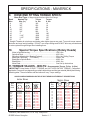
Boom Cylinder Circuit Hoses:
Color Tie
(Code) Hose Size
Green
G
SAE # 6
Green / White
G/W
SAE # 6
Orange
OR
SAE # 6
Orange / White OR/W
SAE # 6
Blue
B
SAE # 6
Blue / White
B/W
SAE # 6
Yellow
Y
SAE # 6
Yellow / White
Y/W
SAE # 6
Red
R
SAE # 6
Red / White
R/W
SAE # 6
Green
G
SAE # 4
Green / White
G/W
SAE # 4
Yellow
Y
SAE # 4
Yellow / White
Y/W
SAE # 4
Hyd. Function
Swing, Back (Rod End)
Swing, Forward (Base End)
Lift, Down (Rod End)
Lift, Up (Base End)
Dipper, In (Rod End)
Dipper, Out (Base End)
Telescope, In (Rod End)
Telescope, Out (Base End)
Head Tilt, Up (Rod End)
Head Tilt, Down (Base End)
Swivel, CW (Rod End)
Swivel, CCW (Base End)
Door, Open (Rod End)
Door, Closed (Base End)
Motor Circuit Hoses:
Color Tie
(Code)
Red
R
Orange
OR
Blue
B
Blue
B
Hyd. Function
Pressure Flow to Motor
Return Flow From Motor
Case Flow From Motor to Boom
Case Flow at Boom to Tank
6.
Hose Size
SAE # 16
SAE # 16
SAE # 8
SAE # 12
HYDRAULIC CYLINDER PRESSURE RATES:
Cylinder Type.......................................................
Cylinder Working Pressure...................................
Welded Cylinders
3000 PSI
Hydraulic Cylnder Repair Specs:
Cylinder
Part No.
02981275
02981278
02981279
02981277
02981280
02961480A
02970710A
02971423
02811000A
02981316
02981315
02981276
Cylinder
Function
Swing
Lift (30 ft.)
Lift (24 ft.)
Dipper
Tilt
Door (Rotary)
Door (Flail Axe)
Slide (Timber Cat)
Door (Ditcher)
Stabilizer
Swivel (Rotary)
Extension
Piston Nut
Torque ft. lbs.
400-500
400-500
400-500
400-500
400-500
150-250
40-60
400-500
150-250
40-60
300-400
300-400
Gland
Torque ft. lbs.
80-120 (Head)
80-120 (Head)
80-120 (Head)
80-120 (Head)
80-120 (Head)
80-120 (Head)
80-120 (Head)
50-60 (Tie Rod)
80-120 (Head)
80-120 (Head)
80-120 (Head)
80-120 (Head)
Maverick (John Deere 6615, 6715 Asy. Man) 02/05
© 2005 Alamo Group Inc.
Section 1 - 5
Seal Kit
Part No.
02982066
02982069
02982070
02982068
02982071
02975528
02975532
02973505
02975528
02982073
02982072
02982067
SPECIFICATIONS - MAVERICK
7.
VALVE SPECIFICATIONS
Valve Type: Multi-Section, Load Sense, Pressure Compensated, Directional control Valve.
Features electro-hydraulic spool actuators for proportional characteristics.
Valve Construction: Multi-Section, Individual Spool, with electro-hydraulic solenoids. Tie rod
bolt together type.
Valve Controller: Mechanical over Electric. 3-axis, multi-function, lever-type joystick.
Valve Porting and Hose Connections: Hoses connect to valve as shown by color code. See
Decal P/N 02981986 below, Electrical connections connect as shown, Reference label on
connector and corresponding solenoid.
8.
Valve Spool Functions & Spec's (Boom Feature):
Main Relief at Inlet 3335 psi - Valve Spool Functions & Specs:
Band
Color
G/W
G
OR
OR/W
B/W
B
Y/W
Y
R/W
R
G
G/W
Spool
No.
1
1
2
2
3
3
4
4
5
5
6
6
Cyl.
Function
Swing
Swing
Lift
Lift
Dipper
Dipper
Telescope
Telescope
Tilt
Tilt
Swivel
Swivel
Travel
Port
Work Port
Pressure
Direction
Relief
Rating
Forward
B
3045 psi.
2.0
Back
A
3045 psi.
2.0
Down
B
1160 psi.
7.92
Up
A
Plug
7.92
Out
B
Plug
3.17
In
A
1160 psi.
3.17
Out
B
2030 psi
3.17
In
A
Plug
3.17
Up
A
Plug
3.17
Down
B
2030 psi
3.17
CW (top) A
2755 psi
6.60
CCW (top) B
2755 psi
6.60
Valve Spool Functions & Specs: The Cylinder Cycle has adjustable settings, slow, medium
and fast, Time Cylinder cycle of unit, Time indicates the time for the Cylinder to travel the full amount of
its extension or retraction. The lift times up and down are taken with the dipper fully extended and begin
with the Deck flat on the ground. All Cycle times are measured at the rated Tractor RPM. Test Times
should vary as according to the setting being used.
Valve Leakage: Maximum internal Valve Leakage from the Cylinder. Ports to Tank at any Valve
Segment, Oil Pressure at 1450 PSI and Oil Viscosity at 102 SSU = 1.25 Cubic Inch / Minute
Standby (Pilot) Pressure: Standby (Pilot) Pressure = 200 to 250 PSI.
Maverick (John Deere 6615, 6715 Asy. Man) 02/05
© 2005 Alamo Group Inc.
Section 1 - 6
SPECIFICATIONS - MAVERICK
9.
HOSE END FITTING TORQUE SPECS:
Hose End Type: 37 Degree Angle End Steel Hose End Fittings*
Dash
Nominal Cyl.
Torque
Torque
Size
Size (in.)
in. lbs.
ft .lbs.
-4
1/4"
140
12
-6
3/8"
230
19
-8
1/2"
450
38
-10
5/8"
650
54
-12
3/4"
900
75
-16
1"
1200
100
-20
1-1/4"
1600
133
-24
1-1/2"
2000
167
-32
2"
2800
233
* Straight Threads do not always seal better when higher torques are used. Too much torque causes
distortion and may lead to leakage. DO NOT over torque fittings and DO NOT allow any contaminants
to enter system through fittings when installing them.
10.
Special Torque Specifications (Rotary Heads)
Motor to Spindle Housing........................................................... 100 ft. lbs.
Spindle to Deck..........................................................................425 ft. lbs.
Spindle to Adjusting Nut (Bearing Preload)............................... 25 in. lbs. Rolling Torque
Blade Bar Leaf Bolts ( 1-1/4" Bolts)....................................... 2000 ft. lbs.
Blade Bar to Spindle Bolts......................................................... 400 ft. lbs.
Blade Bolts................................................................................ 400 ft. lbs.
Motor Plate............................................................................. See Set Up Instructions
11.TORQUE VALUES - BOLTS: Recommended Torque, Ft. lbs.
& (Nm)
IMPORTANT! Listed below IS BOLT TORQUE and NOT APPLICATION TORQUE, Component
Application Torque will vary depending on what is bolted down and the type material (Metal) that is being
bolted together. Thread condition and lubrication will vary Torque settings.
ALWAYS CHECK MARKINGS ON TOP OF BOLT HEAD OR OTHER BOLT DESCRIPTIONS
Inche Sizes
Bolt
Dia.
inch
2 (B)
Plain Head
Metric Sizes
5 (D)
8 (F)
3 Dashes
6 Dashes
Bolt
Dia.
mm
6
8
10
12
14
16
18
20
22
24
27
30
33
36
ft. lbs (*N-M) ft. lbs (*N-M) ft. lbs (*N-M)
1/4
5/16
3/8
7/16
1/2
9/16
5/8
3/4
7/8
1
1-1/8
1-1/4
Not Used
Not Used
Not Used
35 (*47)
55 (*75)
75 (*102)
105 (*142)
185 (*251)
160 (*217)
250 (*339)
330 (*447)
480 (*651)
10 (*14)
20 (*27)
35 (*47)
55 (*75)
85 (*115)
130 (*176)
170 (*230)
300 (*407)
445 (*603)
670 (*908)
910 (*1234)
1250 (*1695)
14 (*19)
30 (*41)
50 (*68)
80 (*108)
120 (*163)
175 (*230)
240 (*325)
425 (*576)
685 (*929)
1030 (*1396)
1460 (*1979)
2060 (*2793)
Maverick (John Deere 6615, 6715 Asy. Man) 02/05
© 2005 Alamo Group Inc.
Section 1 - 7
4.8
8.8
10.9
ft. lbs (*N-M) ft. lbs (*N-M) ft. lbs (*N-M)
5 (*6)
7 (*9)
11 (*15)
20 (*27)
20 (*27)
40 (*54)
37 (*50)
70 (*95)
60 (*81)
100 (*135)
92 (*124)
155 (*210)
118 (*159)
216 (*292)
160 (*217)
270 (*366)
215 (*291)
330 (*447)
285 (*386)
500 (*678)
450 (*610)
875 (*1186)
600 (*813) 1200 (*1627)
800 (*1084) 1600 (*2169)
900 (*1220) 2100 (*2847)
12
25
58
105
140
200
280
355
430
700
1000
1700
2300
3000
(*16)
(*33)
(*78)
(*142)
(*189)
(*271)
(*379)
(*481)
(*583)
(*949)
(*1355)
(*2304)
(*3118)
(*4067)
NOTES
Maverick (John Deere 6615, 6715 Asy. Man) 02/05
© 2005 Alamo Group Inc.
Section 1 - 8
Section 2
Maverick Boom
Tractor Preparation
John Deere Tractor
JD-6615, 6715
Maverick (John Deere 6615, 6715 Asy. Man) 02/05
© 2005 Alamo Group Inc.
Section 2 - 1
General Information / Installation Requirements
GENERAL INFORMATION:
The tools you will need at the assembly site are as follows:
1.
2.
3.
4.
5.
6.
7.
8.
9.
Impact wrench or socket and ratchet set.
Rubber mallet.
Box-end, Allen, and adjustable wrenches.
Alignment pins.
Forklift or hydraulic floor jacks with rolling back boards.
Small chain hoist or block-and-tackle.
Multidirectional Levels.
Hydraulic Filter Buggy or Cart.
Safety shoes, safety glasses, and gloves.
A hard hat should be worn by anyone working under any raised component.
Remember to follow each step closely and cautiously. Be aware of all support personnel at all times.
Keep the assembly area as clean as possible; clean up all spills when they occur. An uncluttered
assembly area and a crew that is sensitive to the hazards involved in putting this implement together
will help prevent accidents. Keep all unauthorized personnel from the area. Do not allow children near
the assembly site nor allow them on or near the tractor after assembly. There is no safe place for
anyone except the operator on the tractor and those assisting with the assembly.
To help you assemble your new Machete Boom and mount it to your tractor, a detailed assembly
instruction Manual is being provided with the mount kit to provide detailed instructions and part
numbers. Please consult this document for specific information. When needed, you can get
additional information or clarification from Your Dealer or Alamo Group Customer Service.
This publication provides general information not specifically for your case or tractor, but, in
connection with the drawings, this publication offers you some valuable assistance - please read
it thoroughly.
These mount kits are made for selected tractors with standard configurations. Only the noted
options and tire sizes listed in the Mounting Specifications will work with these mount kits. Other
options, front axles, or different tire sizes may prevent the mount kit from fitting your nonstandard
tractor. Alamo Group cannot take responsibility for these problems or any modifications made to
the unit.
Throughout these instructions, references are made to right or left directions. Right and left are
determined by sitting on the tractor seat and facing the direction of travel forward always.
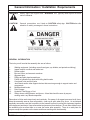
This is the Safety-Alert symbol. When you see this symbol on your machine or in
these instructions, be alert to the potential for personal injury. Follow recommended
precautions and safe operating practices.
DANGER!
A signal word - DANGER, WARNING, or CAUTION - is used with the Safety Alert
symbol. DANGER identifies the most serious hazards.
Maverick (John Deere 6615, 6715 Asy. Man) 02/05
© 2005 Alamo Group Inc.
Section 2 - 2
General Information / Installation Requirements
WARNING!
Safety signs with signal word
serious hazards.
WARNING are typically used to point out more
CAUTION!
General precautions are listed on CAUTION safety sign. CAUTION also calls
attention to safety messages in these instructions.
GENERAL INFORMATION
The tools you will need at the assembly site are as follows:
1.
2.
3.
4.
5.
6.
7.
8.
9.
10.
11.
12.
13.
Welding equipment (including correct head gear, eye shields, and protective clothing.)
Impact wrench or socket and ratchet set.
Rubber mallet.
Box-end, Allen, and crescent wrenches.
Alignment pins.
Phillips and plain-head screwdrivers.
Forklift or hydraulic floor jacks with rolling back boards.
Over head hoist and floor jacks
Jack Stands and/or other support devices that are strong enough to support tractor and
components
Multidirectional Levels.
Paint Scraper.
Hydraulic Filter Buggy or Cart.
Safety shoes, safety glasses, and gloves. A hard hat should be worn by anyone
working under any raised component.
Remember to follow each step closely and cautiously. Be aware of all support personnel at all times.
Keep the assembly area as clean as possible; clean up all spills when they occur. An uncluttered
assembly area and a crew that is sensitive to the hazards involved in putting this implement together
will help prevent accidents. Keep all unauthorized personnel from the area. Do not allow children near
the assembly site nor allow them on or near the tractor after assembly. There is no safe place for
anyone except the operator on the tractor and those assisting with the assembly.
Maverick (John Deere 6615, 6715 Asy. Man) 02/05
© 2005 Alamo Group Inc.
Section 2 - 3
General Information / Installation Requirements
WARNING!
Disconnect the negative lead (ground) from the battery terminal to prevent any
damage to the electrical system.
LEVELING TRACTOR:
TRACTOR MUST be on level ground before assembly is begun. The tractor must be level, All tires
must have the proper amount of air in them as per tire and/or Tractors manufactures recommendations.
DO NOT level tractor by over inflating tires. The tractor can be leveled by jacking it up and putting it on
jack stands if needed.
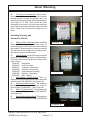
Replacement Oil Filter
Included in the packing box of this unit is a replacement filter element for filter assembly in the tank.
This Mower unit's hydraulic components have been carefully cleaned and packaged at the factory to
prevent contamination from entering the system. However, dust and dirt particles may enter into the
sealed components through transportation, handling, rain, or just sitting in a dirty or harsh environment.
Therefore to assure that the hydraulic system is properly clean, please prepare the area where the unit
is to be assembled. The area should be on a hard concrete floor that has been swept clean of all dust
and contaminants. Unpacked the Mower unit carefully so that the seals on the hydraulic components
are not broken or pulled off.
WARNING!
Before attempting to assemble the mower to the tractor, move the tractor to a clean
solid surface, preferably a concrete shop surface with an over head crane. The crane
should have a rated capacity to lift the heaviest component or assembly. A 5-ton crane
is recommended for the assembly work. If a smaller crane is used, be sure not to
exceed the rated capacity of the crane.
!
Always follow all OSHA crane operating and inspection rules, regulations,
inspection requirements, and recommended practices when using the crane.
!
Never work under any component that is lifted by the crane.
Maverick (John Deere 6615, 6715 Asy. Man) 02/05
© 2005 Alamo Group Inc.
Section 2 - 4
General Information / Installation Requirements
WARNING! Wear personal protective equipment when assembling the mower. As a minimum that
should include:
! Safety Glasses
! Hard Hat
WARNING!
! Safety Shoes
! Hearing Protection
! Gloves
! Welding Helmet
Before attempting to assemble ensure that the tractor engine is off and the tractor
transmission is in the park position with the parking brake engaged.
!
!
!
!
Remove the engine key and keep it in your pocket to prevent inadvertent
starting or movement of the tractor.
Place wheel blocks in front and behind the tractor wheels to prevent the tractor
from moving.
Never attempt to start the tractor unless properly seated in the tractor seat
with the seat belt fastened around you.
Never attempt to operate the tractor and mower controls unless seated in
the tractor seat with the seat belt fastened around you.
WARNING!
Securely block up and support the tractor before attempting to loosen and move the
tires. Failure to properly block up the tractor can result in the tractor to suddenly move
or fall, crushing you or another worker.
!
Never work under any raised component or any component that is not
securely blocked up or supported.
WARNING!
Many components of this mower are very heavy and must be handled by proper
material handling equipment. Do not lift components that weight over 50lbs by
yourself.
!
Use an overhead crane, forklift, or other coworkers to lift heavy items. Ensure
lifted components are securely supported.
!
Never walk or work under a lifted component.
WARNING!
Use extreme care when moving, handling or adjusting the tractor tires. The tires are
extremely heavy and could fall and crush you
!
Use an overhead crane or forklift to move the tires.
!
Properly fasten the tires to the material handling equipment to prevent the tire
from falling.
The hydraulic oil is under high pressure and a hydrauli leak can cause oil to be injected
under the skin.
!
Before starting the tractor ensure all hydraulic connections have bee tightened
!
Never check for leaks with your hands. Use a piece of wood or cardboard to
check for the leak making sure your hands and face are kept away from the
leak area.
!
Repair any leaks before operating the equipments
!
Clean up all oil that has leaked according to the requirements of the oil supplier.
Oil residue on the ground can result in unjury from slipping or falling.
WARNING!
Maverick (John Deere 6615, 6715 Asy. Man) 02/05
© 2005 Alamo Group Inc.
Section 2 - 5
General Information / Installation Requirements
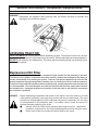
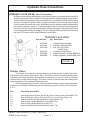
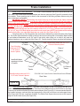
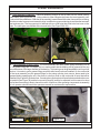
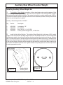
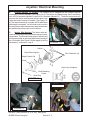
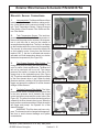
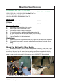
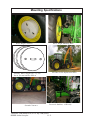
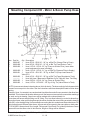
TRACTOR PREPARATION (FIGURE 1 & 2)
1. Temporally remove ROPS and fenders from tractor axle. Move left rear tire out so that it is 50 inches
from the outside of left rear tire to the center of tractor. Then move the right rear tire out so that it is 96
inches between the outside of the left and right rear tires. Refer to your tractor’s Operator’s Manual for
instructions on Rear Wheel Adjustment for your particular tire. FIGURE 1. Hydraflate rear left tire as
much as needed for stability but stay in factory-recommend limit.
FIGURE 1
50"
96"
WARNING:
Never operate the tractor with a loose wheel rim or disc. Always tighten nuts
to the specified torque and at the recommended intervals.
2. Extend front wheels out so that it is 55" inches between the inside of the tires. This will allow
no interference between tire and front mount bracket. FIGURE 2.
FIGURE 2
55"
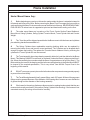
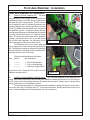
Tractor, Area Cleanliness
The Tractor, all tools and work area must be clean of dirt and debris when assembling any hydraulic
components. DO NOT leave any hydraulic component open to the elements. DO not use any containers
for fluids that are not clean and free of any other liquids. DO NOT use rags/cloth that has lint or fuzz on
them when working on hydraulic components. Keep all hoses capped until you are ready to connect
them.
Maverick
Cleaning
The Maverick Components are designed to be water resistant. But the sealing can be damaged by
Pressure Washers, Steam Cleaners, Solvents or any other harsh chemical that would be used to clean
the units components. It is important to keep all electrical connections and components sealed and dry.
When washing and cleaning this unit it should be done with a non corrosive soap and low pressure spray
of water. It is recommended that all exposed electronic components be covered and protected from
excess moisture.
Maverick (John Deere 6615, 6715 Asy. Man) 02/05
© 2005 Alamo Group Inc.
Section 2 - 6
General Information / Installation Requirements
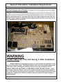
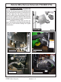
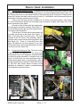
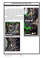
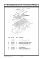
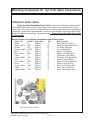
Lay Out Components in Display. It is helpful to lay out the component in as neat a display
as possible. Lay out the Bolts according to size and length. Lay out the Nuts and washer by size. This
will allow you to see how many of each part as you use them and help to identify any missing parts. (See
figure 6) See Mount Kit Specification and Component Identification Section to help ID Components.
All the component that are received should be check and sorted as to what they are.
Shown below is a general example of the components laid out, this is not a lay out of
the components in this mount kit.
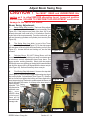
WARNING
DO NOT WELD On This Unit During or After Installation:
DO NOT WELD any components or items on this unit after the installation of the
maverick Boom has begun. The Maverick Boom uses electronic modules and components that could be damaged by welding. Before doing any welding ALL ELECTRONIC MODULES AND DISPLAY COMPONENTS MUST BE UNPLUGGED. Check
the Tractors Opertion, Repair, Service or any other manual from the tractor manufacturer of the tractor to find any special electronic or special proedures about the tractor
electronics. Taking a few minutes to check could save you from a major damage to
the electronics.
Maverick (John Deere 6615, 6715 Asy. Man) 02/05
© 2005 Alamo Group Inc.
Section 2 - 7
NOTES
Maverick (John Deere 6615, 6715 Asy. Man) 02/05
© 2005 Alamo Group Inc.
Section 2 - 8
Section 3
MAVERICK
John Deere Tractor
JD-6615, 6715
Optional
RH Lexan Door
Installation
Maverick (John Deere 6615, 6715 Asy.Man) 02/05
Section 3 - 1
© 2005 Alamo Group Inc.
Lexan RH Door Kit Installation
John Deere 6615 & 6715 Lexan Door Kit No.
Important Instructions
RH Lexan Door Kit.
Remove & Dis-Assembly of Factory Stock Glass Door.
1.
The Removal of Factory Glass Door. The removal of the factory glass door, you will need
to consult the Tractor manufacturers repair assembly manual. Save the parts that are removed from
the factory glass door as they will be needed on the Lexan Door. The installation of the lexan door
will be the same as the factory glass door using most of the same hardware, again consult the tractor
manufacturer assembly / repair instruction in the tractor manufacturer repair / service manual.
Maverick (John Deere 6615, 6715 Asy.Man) 02/05
© 2005 Alamo Group Inc.
Section 3 - 2
Section 4
MAVERICK
Pump & Driveshaft
Installation
John Deere Tractor
JD-6615, 6715
Maverick (John Deere 6615, 6715 Asy. Man) 02/05
© 2005 Alamo Group Inc.
Section 4 - 1
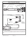
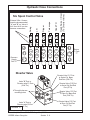
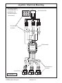
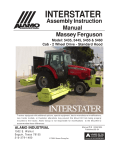
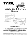
Pump / Driveshaft Schematic
Tractor Engine Pulley
Time Universal Joints
Pump End
Clamp Yoke
Pulley Adpater w/ Mounting
Bolts & Washers (4 bolts)
Driveline Asy
12
12
12
12
12
12
12
12
1234
1234
11
1
11
11
1
12345
12345
12345
4 Driveline Mounting Bolts
Mounting Bolts
12345678901
12345678901
12345678901
12345678901
123456789
123456789
123456789
123456789
12345678901
12345678901
12345678901
12345678901
Pump Mounting
Bolts
Mounting Bolts
1
1
Pump Mount
Plate Bolts To
Tractor Bolster
1234
1234
Pump (Reference)
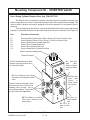
Pump Drive Schematic:
This Section covers the installation of Pump Drive Components, Pump Assembly Some
precautions that must be followed during the Assembly Process before unit is ever started for the first
time.
Maverick (John Deere 6615, 6715 Asy. Man) 02/05
© 2005 Alamo Group Inc.
Section 4 - 2
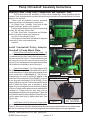
Pump / Driveshaft Assembly Instructions
Installing Pump, Pump Drive Components and Hydraulic Tank:
This Section covers the installation of Pump Drive Components, Pump Assembly and the
Hydraulic Tank. Some precautions must be followed during the Assembly Process and before unit is ever
started for the first time.
1. Tractor must be disabled to prevent accidental
engine start and prevent damage to components.
2. All Fittings, Hose, Cylinders, Tank must be kept
plugged at all times, No part of the Hydraulic
System can be left open at any time during mounting
process, this will keep system clean.
3. All Tools, Work Area, Components and Workers
Hands must remain Clean when working on
any part of the Hydraulic System.
4. All components should be rechecked for tightness
at least twice, Hose routing also double
checked.
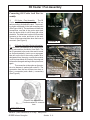
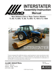
Figure 1
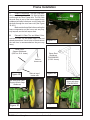
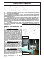
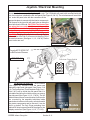
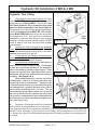
Install Crankshaft Pulley Adapter,
Driveshaft & Pump Mount Plate:
1.
Remove Plate from the front of the Tractor., On
front of the tractor there is a plate that must be removed,
it is retained with two Allen head bolts that can be seen
from the outside (See Figure 1). Remove these two bolts
and remove the cover, this cover will not be used (See
Figure 2) There is already a hole through the front bolster
that will allow the driveshaft to be run through it.
2.
Install Pulley Adapter. The Pulley adapter (P/N
02979790) is a round plate with 4 threaded holes and four
non-threaded holes in it. Notice this pulley adapter will not
have a center hole in it (See Figure 3). The four nonthreaded holes are used to mount the Adapter to the
Crankshaft Pulley using bolts (P/N 02980967) 12 mm X
60 mm long and lockwashers (P/N 00754566) 12 mm
that are supplied in mount kit. The four threaded holes are
used to install the flange yoke of driveline to pulley
adapter Do not use longer bolts to mount Pulley Adapter
to Pulley or Flange yoke to adapter than are supplied with
mounting kit, if longer bolts are used they could go
through adapter and pulley causing damage. Tighten the
four bolts that retain the pulley adapter to the pulley now,
it will be easier than trying to tighten them later. (See
Figure 3 & 4)
Figure 2
4 Non-Threaded Holes
Figure 3
3.
4 Threaded
Holes
Pulley Adapter
P/N 02979790
Install Shaft Half of Driveline with Flange Yoke.
Note the driveline universal joints should be timed (See
Figure 5). Slide the two driveline half assemblies apart and lay the tube half aside for now. Make certain
that the four retaining bolts for the Pulley adapter to the crankshaft pulley have been tightened.
Maverick (John Deere 6615, 6715 Asy. Man) 02/05
© 2005 Alamo Group Inc.
Section 4 - 3
Pump / Driveshaft Assembly Instructions
4.
Check the length of the spline shaft of the driveline is a must. To make certain you have
the right driveshaft, measure the shaft, it should be 12-1/2" long (Measure Shaft Only). If you would need
to cut the shaft, the correct way to cut this shaft is with a saw, after cutting use a file & grinder to chamfer
the cut end and clean the splines. DO NOT cut shaft with a Torch as this will change the hardness
of the shaft.
5.
From the side of the tractor (LH side) slide the Shaft Half of driveline shaft end first down into the
opening below the radiator from engine side, insert it through the existing hole and/or cut hole until the
shaft is pointed toward the front of the tractor, and the flange yoke is over far enough to align with the four
threaded pulley adapter holes.
6.
Align the four holes in the flange yoke of driveline with the four threaded holes in the pulley adapter.
Install the four retaining 7/16" X 1-1/4" long bolts (P/N 02976344) and 7/16" lockwasher (P/N 00022200)
into flange yoke into adapter, tighten them at this time. These four bolts can be tightened by using a
long socket extension run through along side the driveline shaft. If the driveshaft needs to be turned to
reach the pulley adapter mounting bolts. Insert the tube end of the driveshaft over the shaft end of
driveshaft, slide a bar through the yoke of the driveshaft and this will allow you to turn the pulley adapter
to reach hard to get to bolts (See Figure 7 & 17).
7.
Set the tube end of driveshaft aside for now as it will be installed later. But always remember the
driveline universal joint must be aligned (timed) when assembling the driveline halves.
Splined Clamp Yoke
/ Tube End
Figure 4
Figure 5
Figure 6
Figure 7
Maverick (John Deere 6615, 6715 Asy. Man) 02/05
© 2005 Alamo Group Inc.
Section 4 - 4
Flange Yoke
/ Shaft End
Drive Shaft
Assembly
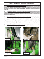
Pump / Driveshaft Assembly Instructions
Install Tank Rail Weldments:
1.
Install Tank Rails. The tank mount plates (P/
N 02981382 LH and RH are the same part number
and will fit either side) can be installed before driveshaft
to engine or after. These will bolt on using the two
holes to the back of the tank mount plate. This will
need to be done before the hydraulic tank can be
mounted, do not tighten these two bolts (two each
side) now as if they are left a bit loose it will be easier
to align the hydraulic tank between them later. (See
Figure 8, 9 & 10) .
RH Side Shown,
123
123
123
123
123
123
123
123
Tractor End
12
12
12
12
12312
123
12
123
12
12312
RH & LH Side are
the same part
Tractor
Figure 8
Figure 10
Figure 9
1 12
11 12
12
Tank
LH Side Shown,
Tube End of
Driveshaft
Spacer (2)
Splined
Clamp Yoke
Pump
Mount Plate
Figure 11
Figure 12
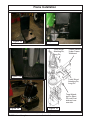
Installing Pump Mount Plate & Tube End of Driveshaft:
1.
Install Pump Mount Plate. Install Front Pump Plate (See Figure 11) use the 2 Spacers on the
JD , Do not install Pump Mount Plate without using these Spacers. The Spacers are for Tractor Hood
Clearance. Insert the 4 bolts and lock washers into Pump Mount Plate and spacers (See Figure 11),
tighten them to required Torque (See Bolt Torque Chart).
Maverick (John Deere 6615, 6715 Asy. Man) 02/05
© 2005 Alamo Group Inc.
Section 4 - 5
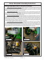
Pump / Driveshaft Assembly Instructions
Installing Pump Mount Plate & Tube End of Driveshaft:
2.
Install Tube End of Driveline / Pump End. Slide the Tube half of driveshaft through Pump Mount
Plate and Tractor Crankshaft Access Hole (See Figure 12 & 13). You will have to align the Universal
joints when doing this (time the Driveshaft). Slide the two together where the Universal are in time (See
Figure 5), this will help the driveshaft to operate smoothly.
3.
Loosen Splined Clamp Yoke. Insert a bar through the Yoke to hold Driveshaft up and to help
loosen the Bolts in the clamp Yoke (See Figure 14). This can be loosened with a hand Wrench or a
Socket whichever is easier for you (See Figure 14). Some times it is easier to test fit the Tube End of
Driveshaft to the Pump while the Pump is on the bench.
4.
Remove Pump Shipping Bracket. The pump is shipped using a bracket that bolts to the pump
and the tank assembly. Before pump can be installed it will have to be unbolted from pump and tank. The
shipping bracket is for shipping only and will not be used. When unbolting pump from tank assembly
there are hoses that will have to be disconnected from pump as tank to pump hoses (filters are
connected when assembly is shipped. Caution must be taken when disconnecting these fittings and/
or hoses to keep the capped to keep contamination out of them.
5.
Coat Pump Shaft w/ Anti-Seize Compound. Coating the pump shaft with a quality Anti-Seize
Compound will help protect the shaft and possibly make it easier if there is a need to disassemble. (See
Figure 16). Hoses will have to be disconnected so pump can be removed from tank assembly during
pump mounting. All hose and fittings need to be covered and sealed to keep them free of contamination.
A recommended way to do this is sandwich bags and rubber bands that will work well.
Figure 14
Figure 13
Pump Shipping Bracket
Figure 16
Figure 15
Maverick (John Deere 6615, 6715 Asy. Man) 02/05
© 2005 Alamo Group Inc.
Section 4 - 6
Pump / Driveshaft Assembly Instructions
Installing Driveline Half to Pump :
1.
Install Pump to Driveline Half. The pump is heavy and will be best to lift it with overhead
hoist (See Figure 18). With the tube half of driveline installed into tractor (align u-joints) and a
bar through the yoke (See Figure 14) install the pump shaft into the clamp yoke, (See Figure 17
Install the clamp yoke of the tube half of driveline onto the pump, slide the clamp yoke on pump
shaft until you have about 1/8" to 1/4" gap between yoke and pump. Do not install yoke so far on
pump shaft that yoke will rub against pump in anyway. Tighten the two bolts and nuts on clamp
yoke at this time. (See Figure 17, 18, 19 & 20)
Figure 17
1
1
1
1
Driveline Tube Half with
Clamp Yoke
12
12
12
12
12
12
12
12
123456
123456
123456
123456
12
12
12
12
12
12
12
12
Installing Pump to Pump Mount Weldment :
1.
Install Pump to Pump Mount Weldment. The Pump has the tube half of driveline attached
and clamp yoke tightened. To install the pump and driveline half it is best to use an assistant or
overhead hoist to help you align the drivelines halves as they are slid together, the Driveline must
be timed (universal joints aligned the same) as shown in the pump & driveline schematic on (See
Figure 5 through 20).. Slide Driveline half and pump together until the shoulder on the pump slide
in the hole on the pump mount weldment. (See Figure 20 & 21).
When installing the pump always keep ports sealed to keep them clean and free of
contamination. The pump MUST be turned correctly. This can be done by making certain that the
pump is mounted the same as it was on the hydraulic tank assembly when it was received.
Install the two 1/2" X 1-1/2" long pump mount bolts (P/N 02892000) and two 1/2"
lockwashers (P/N 00001300). Tighten the two pump mounting bolts. (See Figure 21)
Align Splines on Pump Shaft
with Driveshaft clamp yoke.
Tighten Clamp
Yoke, leave 1/8"
to 1/4" gap
btween yoke &
pump housing is
a must to prevent
rubbing of yokr to
housing.
Figure 18
Figure 19
Maverick (John Deere 6615, 6715 Asy. Man) 02/05
© 2005 Alamo Group Inc.
Section 4 - 7
Pump / Driveshaft Assembly Instructions
Figure 20
1
1
1
1
Must have Gap
between yoke &
pump housing
123
123
Pump Shipped
w/ Hyd. Tank, Valve
Bolts To
is
bolted
to Tank
Tractor Bolster
Pump Mntg Bolts
12
12
12
12
12
12
12
12
12
12
12
12
12
12
12
12
123456789
123456789
123456789
123456789
Check All Components and Bolts :
1.
Check Driveshaft & Pump Installation. The
pump and driveshaft installation needs to be
recheck. Make certain that all bolts and lockwasher
are installed. Make certain that the pump, pulley
adapter and flange yoke of driveshaft are installed square where they bolt together. The pump
has a flange on the housing that must be inserted
into the hole of the pump mount plate. Make
certain that all bolts have been torqued to the
proper specifications (See Bolt Torque Chart). It
is recommended that you mark each bolt as it is
torqued, this can be done with a paint marker or
a marker of you choice so long as the mark can
seen at a glance, this will help not to miss torquing
bolts. (See Pump Schematic at beginning of this
section.).
Maverick (John Deere 6615, 6715 Asy. Man) 02/05
© 2005 Alamo Group Inc.
Section 4 - 8
Figure 21
Push Pump into Pump
Mount until flush
Section 5
MAVERICK
Hydraulic Tank &
Control Valve
Installation
John Deere Tractor
JD-6615, 6715
Maverick (John Deere 6615, 6715 Asy. Manl) 02/05
© 2005 Alamo Group Inc.
Section 5 - 1
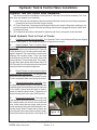
Hydraulic Tank & Control Valve Installation
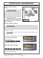
Hydraulic Tank and Control Valve installation:
This Section covers the installation of the Hydraulic Tank and Control Valve Assembly. The Tank
and valve are shipped as an assembly.
1. Locate Tank and Valve Assembly, this will need to be lifted with a hoist, the front bumper weldment
is welded to the front of the tank from the factory.
2. All Tools, Work Area, Components and Workers Hands must remain Clean when working on any
part of the Hydraulic System. All hoses and fittings should remain plugged till ready to install them
to keep them clean.
3. All components should be rechecked for tightness and Hose routing also double checked.
Install Hydraulic Tank to Front of Tractor:
1.
Hydraulic Tank and Valve Assembly, The Hydraulic Tank, Control Valve and Pump are shipped
together (See Figure 1). The Pump should have already been mounted.
2.
Install Hydraulic Tank & Control Valve
Assembly. To install the tank and valve assembly
you should use an over head hoist to lift Tank and
Valve Assembly, as it is heavy and can be damaged if dropped. The hoist will also assist when
aligning the mounting holes. There are three
mounting tabs in the rear of the tank. Mount the
three rear bolts, Three on each side. The hydraulic tank slide under pump and between the LH &
RH Tank rails. Do not remove from hoist until tank
has been bolted on and bolts tightened
Inner
Mounting
Tabs
3.
Rotate Fittings to make better access to
Valve and tank connections, The fittings in the
pump and valve may have to be rotated to make
it more accessible when connecting the hoses.
Figure 1
4.
Tighten Bolts Mounting Tank Rails. After
the bolts that attach the tank to the tank rails are
installed tighten the bolts that mount the tank rails
to the tractor, these were left loose to make it
easier to install the tank to them. Tighten the six
bolts mounting tank to the rails (See Figure 2).
5.
Reconnect Hose to Tank. The hose to the
tank that were disconnected so the pump could
be installed earlier will need to be reconnected
now, make certain that any plugs used to cover
hoses and pump fitting are removed before connecting hoses. Make Certain that all hoses are
reconnected to the correct place, see the hydraulic hose illustration in this section. (See Figure 1A)
Figure 1A
Maverick (John Deere 6615, 6715 Asy. Man) 02/05
© 2005 Alamo Group Inc.
Section 5 - 2
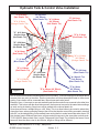
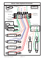
Hydraulic Tank & Control Valve Installation
"J" # 16 Hose
(Red Plastic Tie)
"K" # 16 Hose
(Orange Plastic Tie)
"B" # 8 Hose
(90° Elbow)
(Blue Plastic Tie) "A" # 8 Hose
(90° Elbow)
(Red Plastic Tie)
"C" # 12 Hose
Suction Hose
(No Plastic Tie)
"E" # 4 Hose
(Red Plastic Tie)
"D" # 12 Hose
(Red Plastic Tie)
"G" # 20 Hose
Suction Hose
(No Plastic Tie)
"A" # 8 Hose
(Red Plastic Tie)
"H" # 12 Hose
(90° Elbow)
(Orange Plastic Tie)
"L" # Hose
(Blue Plastic Tie)
"D" # 12 Hose
(Red Plastic Tie)
"B" # 8 Hose
(Blue Plastic Tie)
"G" # 20 Hose
Suction Hose
(No Plastic Tie)
"F" # 4 Hose & Tee
Tank Return
(Blue Plastic Tie)
"H" # 12 Hose
(Orange Plastic Tie)
Figure 2
"E" # 4 Hose (90° Elbow)
(Red Plastic Tie)
"F" # 4 Hose
(90° Elbow)
(Blue Plastic Tie)
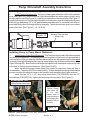
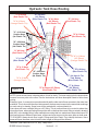
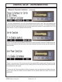
NOTE: Hoses are not shown in drawing above, this is for clarity. The hose routing is for the hoses which
connect from one point to the other. Use the instructions and hose description listed to follow hose
routing. Some hoses will be connected later, Boom hoses and valve hoses.
Example: Hose - A connects to one end marked A and the other end of hose connects to the other item
marked A. This is done with the other letters as well, the hose must connect to the same letter markings
on each end as in drawing. Some hose will be marked with a colored plastic tie.
Some hose will have a straight fitting or a 90° fitting. This is to allow hoses to be routed to where they
clear other items, when connecting hose put the end on that has the correct fitting as noted in drawing
with (90°) or the straight fitting if note marked hose routing that is to make hoses clear other items. Do
Not connect hose to different letter items, all hose end must connect to the same letter on both ends.
TO ID HOSES: Always check Size, Length, Fittings and Color Plastic Tie to identify the hoses. Some
hoses will have the same color tie but the size, length or fittings will be different.
Maverick (John Deere 6615, 6715 Asy. Manl) 02/05
© 2005 Alamo Group Inc.
Section 5 - 3
Hydraulic Tank Hose Routing
Hose Connections To Pump And Hydraulic Tank: (See Figure 2)
Item
A
B
C
Part No.
02981427
02981428
02981429
Qty.
1
1
1
D
E
02981430 1
02981431 1
F
02981432 1
F
G
H
J
K
L
------------02981433
02981462
-------------------------------------
1
1
1
1
1
1
Description
Hose, 8FJX - 8FJX 90° - 24" Lg. w/Red Tie (Charge Filter to Pump)
Hose, 8FJX - 8FJX 90° - 21" Lg. w/ Blu Tie (Case Drain to Tank)
Hose, 12FJX - 12FJX - 23" Lg. (Pump to Suction Filter) hose under
pump and cannot be seen in drawing.
Hose, 12FJX - 12FJX - 31" Lg. w/ Red Tie (Pressure Filter to Supply)
Hose, 4FJX - 4FJX 90° - 35" Lg. w/ Red Tie (Pump Load Sense to Valve (PX)
Connects to top side of pump as shown.
Hose, 4FJX - 4FJX 90° - 20" Lg. w/ Blu Tie (Pump Regulator to Tank)
Connects to bottom side of pump not seen.
Hose #4, Connects here w/ Tee Fitting (Connect to Base End Stabilizer Cyl)
Hose, 20FJX - 12FJX - 24" Lg. (Pump to Suction Filter)
Hose, 12FJX - 12FJX 90° - 20" Lg. w/ Org Tie (Valve Return to Tank)
Hose, # 16 w/ Red Tie (Pressure from Pump to Motor) Bottom Port
Hose, # 16 w/ Orange Tie (Oil Return from Motor) Top Port
Hose. w/ Blue Tie (Oil Return from Oil Cooler to Tank)
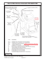
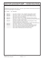
Hose Connections Hydraulic Valve: (See Figure 3)
1. Fittings and Hose Connections to Valve: The fittings are installed in the
valve when it is shipped from the factory, the Valve is mounted to the tank when
it is shipped from the factory. The fittings will have caps and/or plugs covering
all the openings to keep contamination out of the system. DO NOT remove any
caps or plugs at this time. The valve is ONLY listed here to show which fittings
are installed where on the valve. The hoses to the valve, with the exception of
the pressure supply from pump to valve will not be connected until later after
Boom has been installed (See Boom / Head Installation section.
Valve Fittings and Location: (See Figure 3)
Item
Part No.
Qty
Description
1
02981888
02981370
-1
Valve & Fittings Assembly, 6 Spool
Valve Assembly w/o Fittings
2
3
02090800
02972177
2
11
Adapter Hydraulic, Elbow 12MB - 12MJ 90°
Adapter Hydraulic, Straight 10MB - 6MJ
4
5
03200284
02981889
1
1
Adapter Hydraulic, Straight 6MB - 4MJ
Adapter Hydraulic, Straight 10MB - 6MJ
6
7
02972208
02975438
1
1
Valve Solenoid Assembly
Adapter Hydraulic, Straight 8MB - 8FJX
8
02981890
1
Adapter Hydraulic, Straight 8MB - 6MJ
Maverick (John Deere 6615, 6715 Asy. Man) 02/05
© 2005 Alamo Group Inc.
Section 5 - 4
Directional Control Valve Fittings
FIGURE 3
"A"
"B"
Ports Ports
Pump Pressure
Port
Tank Return Port
Maverick (John Deere 6615, 6715 Asy. Manl) 02/05
© 2005 Alamo Group Inc.
Section 5 - 5
Directional Control Valve Fittings
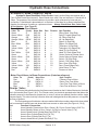
HYDRAULIC HOSE CODES AT VALVE
Hydraulic Hose Band Mark Color Codes: Hose's and/or fittings are marked with a
Color Coded Plastic Band around it. Some Bands are a solid Color and some are Colored with a
Stripe. The purpose of the colored bands are to provide a quick reference for hose and port
connection. A metal band is also attached to the hose, on that band is an Alamo Industrial Part
Number for reference if needing a replacement hose. Always Check Hose Size, Color Code
& Part Number (See Figure 5)
Boom Cylinder Circuit Hoses:
Color Tie
Green
Green / White
Orange
Orange / White
Blue
Blue / White
Yellow
Yellow / White
Red
Red / White
Green
Green / White
Green
Green / White
Yellow
Yellow / White
Orange
Red
(Code)
G
G/W
OR
OR/W
B
B/W
Y
Y/W
R
R/W
G
G/W
G
G/W
Y
Y/W
OR
R
Hose Size
SAE # 6
SAE # 6
SAE # 6
SAE # 6
SAE # 6
SAE # 6
SAE # 6
SAE # 6
SAE # 6
SAE # 6
SAE # 4
SAE #4
SAE # 4
SAE # 4
SAE # 4
SAE # 4
SAE#12
SAE#12
Port
A
B
A
B
A
B
A
B
B
A
A
B
-------T
P
Diverter
--------------------P2
P1
C4
C1
C3
C2
----
Hyd. Function
Swing, Back (Rod End)
Swing, Forward (Base End)
Lift, Down (Rod End)
Lift, Up (Base End)
Dipper, In (Rod End)
Dipper, Out (Base End)
Telescope, In (Rod End)
Telescope, Out (Base End)
Head Tilt, Up (Rod End)
Head Tilt, Down (Base End)
Control Valve tor Diverter valve
Control Valve to Diverter Valve
Swivel, CW (Rod End)
Swivel, CCW (Base End)
Door, Open (Rod End)
Door, Closed (Base End)
Valve Return To Tank
Pressure to Valve.
Motor Circuit Hoses to Boom Connections: (Listed as reference)
Color Tie
Red
Orange
Blue
Blue
(Code)
R
OR
B
B
Hose Size
SAE # 16
SAE # 16
SAE # 8
SAE # 12
-----
Maverick (John Deere 6615, 6715 Asy. Man) 02/05
© 2005 Alamo Group Inc.
Section 5 - 6
Hyd. Function
Pressure Flow to Motor
Return Flow From Motor
Case Flow From Motor to Boom
Case Flow at Boom to Tank
Hydraulic Hose Connections
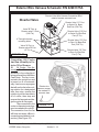
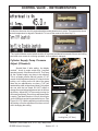
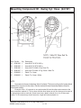
HYDRAULIC LOCK VALVE:
(Head Tilt Function)
An Electric Solenoid Operated Hydraulic Lock Valve (Figure 4) is incorporated in the Head Tilt
Function to prevent excessive (Head Lift Cylinder) leak down during storage or transportation.
The Solenoid which operates this valve is normally in the Locked position until Head Lowering
function is actuated at Joystick. When Joystick is actuated to lower Head an electric signal
is sent to solenoid to open Lock valve. When the function to raise the Head is activated there
is no electric signal from Joystick. The pressure against the valve when head is being raised
will force Valve open like a relief Valve allowing Oil to pass through it. If this valve will not open
it could stop head from lifting or dropping. The valve is plumbed into the Hydraulic Circuitry of
the Head Tilt Function and is located near the Control Valve.
Hydraulic Lock Valve
Item Part No.
Qty. Description
1
2
02972208
02971425
02975198
-1
1
3
4
5
02975199
02975438
02981890
1
1
1
Solenoid Valve Assembly
Seal Kit, f/ solenoid Valve
Coil, 12V- DC w/Dual
8-32NF Studs
Cartridge, Solenoid Valve
Adapter Hydraulic, Straight 8MB-6FJX
Adapter Hydraulic, Straight 5MB - 6MJ
FIGURE 4
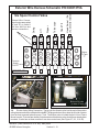
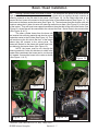
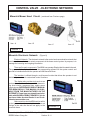
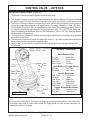
Diverter Valve.:
The Diverter Valve bolts onto the front frame mount bracket on the LH side of the tractor,
the holes are in the bracket (See Figure 5 , 6 & 7). The Diverter valve is a electrical operated valve
that allows the hydraulic pressure to be shared to operate two (or more if valves are stacked)
functions with a single pressure supply. This valve is strictly a diverter valve and is designed to
direct the pressure, not regulate the flow or pressure.
The Port openings on this diverter valve are marked with letter number codes which show
which port is connected to which hose and where that hose connect on other end (See Figure 5,
4 & 7)
Port
Function & Connection
P1
P2
C1
C2
C3
C4
Hose Hyd Pressure f/ Door / Swivel (B) Port on Control Valve (Green/White Tie)
Hose Hyd Return to Door / Swivel (A) Port on Control Valve (Green Tie)
Hose to Head Swivel Cylinder Base End (Green/White Tie)
Hose to Door Cylinder Base End (Yellow/White Tie)
Hose to Door Cylinder Rod End (Yellow Tie)
Hose to Head Swivel Cylinder Rod End (Green Tie)
Maverick (John Deere 6615, 6715 Asy. Manl) 02/05
© 2005 Alamo Group Inc.
Section 5 - 7
Head Swivel / Door
(To Diverter Valve)
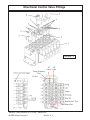
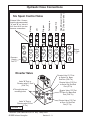
Hydraulic Hose Connections
B
B
Head Tilt
Telescope
B
B
B
B
AA
12
AA
10
AA
8
AA
6
AA
4
AA
1
AA
11
AA
9
AA
7
AA
5
AA
3
AA
2
A
Pressure
Supply
Port "P"
Dipper
Lift
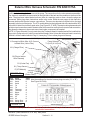
External Wire Connections for valve are marked
"A" and "B" on Valve &
AA1 thru AA12 on wire
harness connections
Swing
Six Spool Control Valve
A
A
A
A
A
"B"
"B"
"B"
"B"
"B"
"B"
G/W
OR/
W
B/W
Y/W
R
G/W
G
OR
B
Y
R/W
G
"A"
"A"
"A"
"A"
"A"
"A"
Return
To Tank
"T"
Diverter Valve
Diverter Valve "C1" Port
to Swivel Cyl Base
End Port (G/W Tie)
Valve "B" Port to
Diverter valve P1 Port
(G/W Tie)
C2
C3
SAE 4
P2
Valve "A" Port to
Diverter valve P2 Port
(G Tie)
FIGURE 5
Maverick (John Deere 6615, 6715 Asy. Man) 02/05
© 2005 Alamo Group Inc.
Section 5 - 8
VS . 125/F
P1
4 Through holes are
mounting holes
Diverter Valve "C4" Port
to Swivel Cyl Rod End
Port (G Tie)
Diverter Valve "C2" Port
to Door Cyl Base End
Port (Y/W Tie)
Diverter Valve "C3" Port
to Door Cyl Rod End
Port (Y Tie)
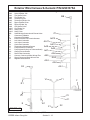
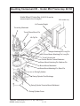
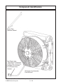
Oil Cooler / Fan Assembly
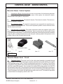
Connecting Oil Cooler And Fan Assembly:
1.
Oil Cooler / Fan Assembly.
The Oil
Cooler and Fan Assembly connects to the two
tank mounting rails behind the tank . The mounting holes are already in the tank mounting rails
(See Figure 1A & 9). The tank hoses will have two
connections, one that is the motor case drain
from the boom which is a #16 hose with a blue
plastic tie. The other hose is a short # 16 hose that
connects to the cooler and them to the tank.
These will be connected later when the boom is
mounted. (See Figure 9)
Diverter Valve
FIGURE 6
2.
Oil Cooler Operation Design Information.
The Oil cooler / fan assembly is for cooling the oil
being returned from the Motor Case Drain. The
fan is connected to the control box and is turned
on & off automatically. It set to run on a program
that will run the fan in the cooling rotation for a
designated time, then stop, reverse the rotation
(cycle to clean debris off of cooler), then stop and
reverse the fan again and begin the cycle all over
again.
The connection to the cooler on the exterior wire harness is marked with code R1. The
connection from the fan will have two wires, a
Blue (+ connection) and a black (- connection)
(See Figure 8).
Swivel Cyl. Base End C1 Port (G/W Tie)
From Valve "A"
Port to P1 Diverter
Port (G / WTie)
Valve "A" Port to
P2 Diverter Port
Port (G Tie)
FIGURE 7
Exterior wire harness connection marked R1 connects
here
FIGURE 9
FIGURE 8
Maverick (John Deere 6615, 6715 Asy. Manl) 02/05
© 2005 Alamo Group Inc.
Section 5 - 9
Swivel Cyl. Rod
End C4 Port (G Tie)
Door Cyl.
Base End
C2 Port
(Y/W Tie)
Door Cyl. Rod End
C3 Port (Y Tie)
NOTES
Maverick (JD-6615, 6715 Asy. Man.) 02/05
© 2005 Alamo Group Inc.
Section-5-10
Section 6
Maverick Boom
Main Frame Installation
John Deere Tractor
JD-6615, 6715
Maverick (John Deere 6615, 6715 Asy. Man) 02/05
© 2005 Alamo Group Inc.
Section 6 - 1
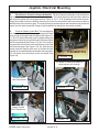
Frame Installation
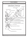
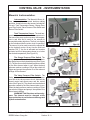
Under Mount frame Asy:
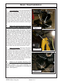
1.
Before beginning any repairs on this section make certain the boom is extended outward to
full extend and laying on the floor. Before removing the Boom Pivot Pin support the boom with an
overhead hoist so as when Pie is removed boom can be lifted out of the way. NEVER REMOVE ANY
PINS OR BOLTS unless boom is supported at pivot end and head end is resting on the floor.
2.
The under mount frame asy is made up of the Turret, Center Section Frame Weldment,
Boom Mount, Swing Cylinders, Swing Cylinder Trunnion Mount, Turret Cylinder Link and Counter
Weight.
3.
The Turret Asy will be shipped assembled to the Boom mount with the hoses and cylinders
plus attaching hardware assembled to it.
4.
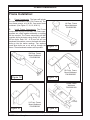
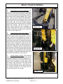
The Swing Cylinders have replaceable mounting bushing which can be replaced by
removing the bottom cover and trunnion mount weldment. The Cylinders can be dropped down
enough to replace the bushing. The replace the Trunnion Mount weldment. Also by removing the
cylinders the Turret Cylinder link can be removed.
5.
The Turret assembly has a large bearing assembly bolted to it and then bolted to the Boom
Mount. This Bearing CANNOT be removed (or replaced ) unless the Boom is disconnected from it
first. When disconnecting boom make certain the boom is supported as not to fall (See Step 1). The
Bolts retaining the turret to the bearing and the bolts connecting bearing to the Boom Mount MUST
be torqued to the required specification, This is very critical. See the Bolt Torque Chart in the
beginning of this manual.
6.
DO NOT remove any mount pins and/or bolts unless the components are supported properly
to prevent them from falling
7.
The Turret Bearing Assembly has 3 grease fittings, each 120° apart. All three of these grease
fittings must be greased because of the diameter of the bearing this to ensure an even distribution
of grease though out the diameter of the bearing assembly.
8.
If the hoses for the swing cylinders are disconnected or replaced make certain that they are
reconnected correctly as shown in this section (Swing Cylinder Hose Routing). If the hoses are not
connected correctly the swing will not function correctly.
Maverick (John Deere 6615, 6715 Asy. Man) 02/05
© 2005 Alamo Group Inc.
Section 6 - 2
Frame Installation
Under Mount Frame Asy
(24 & 30 ft are the same except for the LH weight)
30 ft model only
LH Counter Weight
Turret Asy, Machined
Turret / Boom Mount Pin
Lift Cyl Pin
Weight Attaching Pin, Long Pin
Boom Mount Attaching Pin, Long Pin
Turret Cylinder Link
Center Section Frame Weldment
Boom Mount Attaching Pin, Medium Pin
Boom Mount, Machined
Boom Mount Attaching Pin, Short Pin
Swing Cylinders
Swing Cylinder Pivot Bushings
Swing Cylinder Trunnion Mount Weldment
Swing Cylinder Cover
Maverick (John Deere 6615, 6715 Asy. Man) 02/05
© 2005 Alamo Group Inc.
Section 6 - 3
Frame Installation
Frame Installation:
1.
Frame Components. The frame will include
the rear axle mounts, a LH & RH Frame rail. Two
front frame mounts, a LH & RH. One center frame
weldment. (See Figure 17, 18, 19, 20 & 21)
LH Rear Frame
Mount Weldment
P/N 02982390
2.
Install Frame Components. The Frame
components will only fit one way. The Frame components are a Bolt together assembly no welding
will be required. The Frame components will bolt
together and to the tractor using mostly 3/4" and/or
20 mm bolts. Each 3/4" & 20 mm bolt will use
hardened flat washers, one on the head side when
bolts go into the tractor castings. Two washers
used when bolts use a nut and go through the
frame. These hardened washers are important.
Figure 17
RH Rear Frame
Mount Weldment
P/N 02982388
RH Front Frame
Mount Weldment
P/N 02982380
Figure 18
Figure 19
Center Frame
Weldment
P/N 02981168
LH Front Frame
Mount Weldment
P/N 02982383
Figure 20
Figure 21
Maverick (John Deere 6615, 6715 Asy. Man) 02/05
© 2005 Alamo Group Inc.
Section 6 - 4
Frame Installation
3.
Install Rear Frame Mount Rails. Rear frame
rails consist of a LH & RH. We have started with the
Left Hand Rail. Using a floor jack to lift the rail up
under the rear axle. Install the bolts up and into the
tractors rear axle housing and snug the bolts down.
Support the frame rail with a jack stand (or leave the
floor jack under it). (See Figure 17 & 22).
The RH Rear Frame Rail will basically install
the same, bolts up under the tractor axle housing
with the three point stabilizer bolt back up under
frame rail (See Figure 18 & 23). The RH Rail looks
different at the rear because the boom rest will bolt
here later.
LH Rear
Frame
Mount
Weldment
P/N
02982390
4.
Install Front Frame Mount Rails. The Front
Frame mount rails will consist of a RH & LH (See
Figure 19, 20, 24 & 25) These will only fit one way as
they have a gusset reinforcement on one side that
will be showing to the outside when installed. These
can be lifted by the technician installing them. The
LH and RH will install the same way, Using 4 bolts
each that screw into nuts on the inside of tractor
frmae on the side of the tractor (See Figure 24 &
25). Make certain that all of these mounting bolts
have hardened flatwashers on on both side of
frame, Bolt heads or nuts should not be againsr
frame.
Figure 22
RH Rear
Frame
Mount
Weldment
P/N
02982388
Figure 23
LH Front Frame
Mount Weldment
P/N 02982014
RH Front Frame
Mount Weldment
P/N 02982380
Figure 25
Figure 24
Maverick (John Deere 6615, 6715 Asy. Man) 02/05
© 2005 Alamo Group Inc.
Section 6 - 5
Frame Installation
5.
Install Center Frame Weldment. The Center Frame Weldment has a front and a back side (LH
& RH side). The Center frame must be installed with the two openings (See Figure 26) toward the front
of the tractor. These openings are to allow for the movement of the swing cylinders when moving the
boom to the boom rest position.
IMPORTANT NOTE: When bolting the center frame up to the front and rear frame mounting
rails the bolts on the RH turret side must have the bolts installed from the bottom with the bolt heads on
bottom under center under frame and the nuts on top (See Figure 27 showing nuts on top). The reason
the nuts must be on top is so the bolts will not hit the swing cylinders when the turret assembly has been
mounted. The Bolts that are used to mount center frame are not the same lentgh. The 8 bolts for the rear
fame bracts (bolts that face the rear of the tractor) will be 3/4" X 3-1/2" long. The other twelve bolts will be
3/4" X 2-1/4" long. All 20 Bolts that at are used to mount center frame MUST have hardened flat washers
install on both sides, one under Bolt Head and one under Nut (See Figure 26 & 27)
Using floor jacks (or Fork lift) position the center frame weldment up under the tractor (See Figure
27). The center frame weldment will bolt to the front and rear mounting rails on both sides. Make Certain
to use hardened flatwashers on all 3/4" and 20 mm bolts, when using nut on bolts it will need two
hardened washers, one on each side (See Figure 27) . Double check the frame mounting bolt tightness.
RH Side
of Tractor
Rear Top Mounting Holes use 3/4" X 2-1/
4" bolts in these 4 places
Front Mounting
Holes use 3/4" X
2-1/4" bolts in
these 8 places
Rear of
Tractor
Install with these
openings to front
of tractor
LH Side of
Tractor
Front of
Tractor
Rear Mounting Holes use 3/4" X
3-1/2" bolts in these 8 places
P/N 02981168 Center Section Under Mount Frame Wldmnt
Rear View
Figure 26
6.
Install Boom Rest Weldment. The boom rest weldment for the 24 foot boom and the 30 ft.
boom are not the same (See Figure 29). The boom rest weldment bolts to the RH Side on the Rear
Frame mount weldment behind the tractor axle weldment (See Figure 30). It is recommended that this
be installed using an overhead hoist and supported by the hoist until boom rest and support brace
(See Figure 28 & 30) are completely installed. The Boom Rest Support also serves as the top axle
strap for the RH Axle mount (See Figure 30).
Maverick (John Deere 6615, 6715 Asy. Man) 02/05
© 2005 Alamo Group Inc.
Section 6 - 6
Frame Installation
7.
Install LH Axle Strap. The Axle Strap bolts
down over the top of the Axle (LH Side) and bolts
run through the Rear Frame rails. The RH Side
the axle strap is part of the boom support brace
weldment and also bolts down over the axle with
the bolts through the rear frame rail (See Figure
30 & 31)
Make certain that all the bolts mounting the
frame components and the boom rest are properly torqued, see the bolt torque chart.
Shown from RH
side of tractor
Rear
8.
Reinstall LH Rear Tire and Wheel. Reinstall the LH rear Tire and Wheel now if it has not
already been done. Use a hoist to lift and secure
the rear tires is recommended as they are very
heavy.
Front
Figure 27
Boom Rest
Support Weldment
(f/24 ft or 30 ft.. boom)
Boom Rest
Weldment
P/N 02982392
(f/ 30 ft. boom)
Bolts to
boom rest
Figure 28
Bolts to top of
tractor axle
Figure 29
LH side of tractor
Upper axle strap
P/N 02974704
RH Side Boom Rest
Support & Axle Strap
Weldment
Figure 31
Figure 30
Maverick (John Deere 6615, 6715 Asy. Man) 02/05
© 2005 Alamo Group Inc.
Section 6 - 7
Frame Installation
Counter Weight Installation 24 & 30 Foot Boom:
1. Counter Weight (CWT) Installation. The Counter weight (See Figure 1 ) mounts on the LH side Under
Frame Weldment. Its is retained with three pins, the long pin on top, the short pin at the rear and a short
pin at the front. Using a hoist or other sufficient lifting device align the weight with the frame. The Frame
for the weight will slide over the under frame until the upper long pin is aligned with the mounting tube of
the weight and the mounting tubes of the under frame. Install the long mounting pin. The front and rear
pin holes should be aligned, install the short pins front and rear. The short pins are retained using a nut
and bolt. The long pin uses two large cotter pins, install cotter pins and bend end of them to secure them.
(See Figure 32 , 33, 34 & 34A). Counter Weight willl mount under tractors factory fuel tank (See Figure
24A).
2. Additional Counter Weight (CWT) Installation: The 30 foot boom model has an additional bolt on weight
at the counter weight. This additional weight bolts to the weight weldment on the 30 foot model only (See
Figure 32)
Weight Attaching Pin,
Short Pin Rear side
LH Counter Weight 24 or
30 Foot Boom
Weight Mount
Attaching Pin,
Long Pin
Center Section
Under Frame
Weldment
Figure 32
Additional bolt on Weight Used
Weight Attaching Pin, on 30 ft boom models only
Short Pin front side
3. Wheel Counter Weight (CWT) Installation: The Wheel counter weight is in addition to the frame
mounted counter weight, they both must be used together, the 30 foot boom will have an additional frame
mounted counter weight bolted on, (See Figure 32, 33 & 34). All these weight are in addition to adding liquid
weight into the Left rear tire. The proper amount of counter weight is not complete until all these weight
have been installed.
Turret Assembly Installation 24 & 30 Foot Boom:
1. Turret Assembly. Theturret assembly is shipped assembled with the hydraulic swing cylinders,
hoses, pivot bearing assembly, boom mount weldment and mounting pins installed (See Figure 35 & 36).
2. Under Frame Weldment. The Under frame weldment center section is designed for the turret
assembly to mount on the RH side. Remove the one long mounting pin and the front and back short
mounting pins (See Figure 36 & 37). Check to make certain the mounting bolts mounting the center ubder
frame weldment are installed with the bolt heads unter frame weldment and nuts are on top visible looking
down, if they are in wrong the swing cylinders will hit the bolts causing damge to cylinders and bolts. (See
Figure 37)
Maverick (John Deere 6615, 6715 Asy. Man) 02/05
© 2005 Alamo Group Inc.
Section 6 - 8
Frame Installation
Figure 33
Figure 34
Turret Mount
Attaching Pin,
Long Pin
Center Section
Under Frame
Weldment
Figure 34A
Turret Mount
Attaching Pin,
Long Pin
Turret Attaching Pin, Short
Pin, one Front
side and one
rear side.
Figure 36
Figure 35
Maverick (John Deere 6615, 6715 Asy. Man) 02/05
© 2005 Alamo Group Inc.
Section 6 - 9
Frame Installation
3. Turret Assembly Installation. Theturret assembly mounts on the RH side onto the center section
under frame (See Figure 36 & 37) . Using a hoist (or other lifting device) lower the turret assembly until
it is level with the underframe. Slide the turret assembly inward toward the under frame until the retaining
pin tube on under frame an turret assembly align. Installthe long upper retaining pin and then the two small
front and rear pins. The long upper pin is retained with two cotter pins that need to be bent over on the
ends. The short pins are retained with nuts and bolts (See Figure 36 & 38).
Figure 38
Figure 37
4. Turret Assembly Grease Fittings. The turret assembly has three grease fittings around the OD of
it. The grease fittings are 120° apart, this is to make certain that the bearing will be greased all the way
around because of the large diameter of the bearing. This bearing must be greased before unit is put into
service. It is easier to get to grease fittings now than after boom has been installed. On the under side
of the turret assembly are the grease fittings for the swing cylinder pivot mounts, these need to be
greased before operating the unit. Also there is a bolt on cover on the under side of turret that will be
installed (See Figure 40) at a later time. Greasing the cylinder pivots will need to be done before the cover
is installed (See Figure 39) and the boom swing stop will need to be adjusted, but this cannot be done
until a later time making it best to leave this cover of until then. After greasing components at assembly
of unit operator should consult the operators manual for maintenance requirements.
Figure 39
Figure 40
Maverick (John Deere 6615, 6715 Asy. Man) 02/05
© 2005 Alamo Group Inc.
Section 6 - 10
Front Axle Stabilizer Installation
Front Axle Stabilizer Kit Installation:
1.
Install Front Axle Stabilizer Kit. The front
axle stabilizer kit will consist of all brackets and
hardware to install to front RH side of 4 wheel drive
axle and RH side of tractor frame. This kit is tied to
the oil supply from the Lift Cylinder for the boom, the
pressure supply hose is tee'd to the "B" port of valve
for the lift cylinder and connected to the rod end of
the stabilizer cylinder. Install the cylinder with the
rod end toward the axle and the base end of cylinder
up to the bracket (See Figure 41) bolted to tractor
frame. The hose connects at base end of stabilizer
cylinder will connect with a tee to the tank return
port for the Pump regulator, it is a Number 4 hose
with a blue plastic tie at the front side of tank.
The Brackets bolt to the tractor axle and
form a clamp around front axle housing (See Figure
42). The Stabilizer cylinder is charged only when the
boom lift cylinder is activated and is controlled automatically with the boom lift controls.
Item
The three axle brackets are as follows
Part No
Qty Description
1
2
3
-------------------------------
1
1
1
Figure 41
Rear of Axle Bracket
Front of Axle Bracket
Stabilizer Support Brckt
See Mount Kit & Component ID section for Axle
Stabilizer component list.
Figure 42
2.
Install Front Axle Stabilizer Cylinder Hoses. The front axle stabilizer kit will consist of two
hoses. One hose will connect to the rod end of the stabilizer cylinder and connect to a Tee fitting on
the "B" of the control valve where the boom lift cylinder hose connects, See the valve / cylinder hose
routing in the boom / head installation section.
The Second hose connect to the base end of the stabilizer cylinder and connect to the return
port on the tank with a Tee fitting at the "F" Tank return connection. See the tank hose routing in the
boom / head installation section for schematic of hose connections.
Maverick (John Deere 6615, 6715 Asy. Man) 02/05
© 2005 Alamo Group Inc.
Section 6 - 11
NOTES
Maverick (John Deere 6615, 6715 Asy. Man) 02/05
© 2005 Alamo Group Inc.
Section 6 - 12
Section 7
MAVERICK
Standard Wheel Weight
&
Auxiliary Wheel Weight
Installation
John Deere Tractor
JD-6615, 6715
Maverick (John Deere 6615, 6715 Asy. Man) 02/05
© 2005 Alamo Group Inc.
Section 7 - 1
Rear Wheel Counter Weight
Fill Left Rear Wheel with Liquid:
The Left Rear Wheel must be filled with liquid. Alamo Industrial recommends a Calcium
Chloride Water Mixture. The recommended Ratio of a 30 / 70 mix (30% Calcium Chloride and 70%
Water), this mixture will add weight at about 10.5 lbs per gallon. Follow the Mixture procedures
furnished by the Manufactured of the Brand of Calcium Chloride that you are using. It is also
recommended that a trained person installs the calcium Chloride. Calcium Chloride must be added
in addition to the Steel Wheel Weight and the Counter Weight that hangs on the Left Side. It is Not
recommended to use straight Water in the Wheel as this would not provide protection against freezing.
A 30/70 Calcium Chloride Water mixture provides antifreeze to approx -50 deg. F. below 0.
Rotate Washer to Match Bolt
Circle dia. and Washer fits into
Wheel Weight Slot.
4
3
2
1
Bolt is shown extra long in
drawing for illustration only
Item
Part No.
Qty
Description
1
2
3
4
02979603
02971569
02970758
5JRC1490
3
3
1
3
Hex Head Bolt, 7/8" NC X 16"
Wheel Weight Washer, Special
Wheel Weight Casting, 1400 lbs.
Locknut, Top Lock 7/8" NC
Note: some Older Units used a All Thread Rod with Hex Nuts Lock Nuts, with Flat Washer
and Lock washer. This was replaced with the Bolt Type shown above. These Bolt and Nut
combinations will replace the old All Thread type.
Figure 1
Maverick (John Deere 6615, 6715 Asy. Man) 02/05
© 2005 Alamo Group Inc.
Section 7 - 2
Rear Wheel Counter Weight
Installing Wheel Weight
1.
This Wheel Weight is 1400
lbs. Always use caution when
working with it.
2.
Locate the three Holes in
LH Rear Wheel. Make sure these
holes are 15/16" dia. if not, they
must be reamed out.
3.
Lift Left Rear Tractor
Wheel till it just clears the ground.
This will allow the Wheel to be
rotated when aligning mounting
holes for Weight.
4.
Using a forklift, lift Wheel
Weight into Wheel. When Wheel
Weight is centered in Wheel Secure Forklift and Set Parking Brake
on Forklift. Insert one of the three
bolts through Weight and Wheel
(Rotate Wheel to align holes if
needed). Install a Hex Lock Nut on
inside. Insert the other two Bolts
through Weight and Wheel and
start the other two Locknuts. Do
not tighten yet. (See Figure 2)
Wheel Weight Mntg
Locknuts
Figure 2
5.
Looking at the outside
make sure the three special Washers (Figure 1 Item 2) are aligned
with the Slots in the Wheel Weight.
Tighten the three Bolts now. You
will need an assistant to hold the
other Side while you are tightening
the Bolts. While tightening Bolts,
check to make sure the three special washers are seated correctly.
If these Bolts are tightened and
washer are not seated into the
recess on Wheel Weight, damage will occur. (See Figure 3)
Wheel Weight
Special Washers
Mounting
Bolts
Part #
02971569
(3)
6.
Remove forklift away from
Wheel and Weight. Recheck tightness of Wheel Weight retaining
Bolts. Bolts should torque to 500
ft. lbs.
Figure 3
Maverick (John Deere 6615, 6715 Asy. Man) 02/05
© 2005 Alamo Group Inc.
Section 7 - 3
Wheel Weight
1400 lbs.
Auxiliary Rear Wheel Counter Weight
Installing Auxiliary Wheel Weight Kit.
1.
The Auxiliary Wheel Weight is made up of three steel plates and mounting hardware. Each
Auxiliary Weight weighs approx 136 lbs. When all three are installed on the existing 1400 lb. weight it
will increase the wheel weight by 408 lbs. This makes the total bolt on wheel weights equal 1800 lbs.
This will not include the amount of weight to the tire from the installed liquid which, will vary with the size
of the tire and the liquid that is added.
Auxiliary. Wheel Weight Kit No. 02976671
Qty
Part No.
Description
2
2
2
3
00012200
00012300
00760266
02976644
Lockwasher, 7/8"
Nut, 7/8" NC
Bolt, 7/8"-NC X 5-1/2 GR8
Auxiliary Wheel Weight Plate, 136 lbs Each
2.
Install Auxiliary Wheel Weights. The Auxiliary Wheel Weight bolt to the larger 1400 lb. wheel
weight. There are two slots in the large weight that the 7/8" bolt heads will slide into. It is recommended
that the tractor wheel is in position so these two slots has one facing front and one to the rear. Slide the
two 7/8" bolts into the slots, the slots will prevent the heads of the bolts from turning. The Bolts in the
large wheel weight will have to be aligned to the proper distance apart, to match the distance of the holes
in the auxiliary weights. Slide the auxiliary weight over the two bolts, do this with all three weight for this
kit. Install the lockwashers and hex nuts. Tighten the bolts to required tightness. See bolt torque charts
in tractor preparation section.
Wheel Weight
P/N 02970758
Figure 4
Auxillary Weight
Attaching Stots
Maverick (John Deere 6615, 6715 Asy. Man) 02/05
© 2005 Alamo Group Inc.
Section 7 - 4
Figure 5
Section 8
MACHETE
Joystick - Wire Harness
& Valve Installation
John Deere Tractor
JD-6615, 6715
Maverick (John Deere 6615, 6715 Asy. Man) 02/05
Section 8 - 1
© 2005 Alamo Group Inc.
Joystick / Electrical Mounting
Installing Wiring Harness and Joystick:
1.
Preparing Tractor Floor Mat. First thing to do is remove the Battery Cables from Battery, Do
Not perform any work on Tractor or Boom Electronics unless this has been done. Raise the Floor Mat
up on the RH Side by the RH Door, You will need to fold it back approx. 12 to 14 inches (See Figure 1
& 2). DO NOT Tear or Cut any Holes in Rubber Floor Mat, as it will NOT be required.
You may find a rubber plug or you may have to cut a hole with a hole saw, this will have to be decided
during installation. If you need to cut a hole, check the under side of cab for any obstruction or any
component that might be damaged before you cut the hole. The hole is going to have to be oblong in
order for the plug to go through it. Measure Wire Harness plug Coded G1 to determine the size hole.
In Figure 2 below the tractor had two holes from the tractor manufacturer, Check to make certain the
installation will not interfere with the operators normal functions. (See Figure 1 & 2). Floor mat can be
reinstalled over wire harness with out cutting any holes in floor mat.
Cut Hole in flor of
cab if not one
already in it.
FIGURE 1
FIGURE 2
2.
Remove Tractor RH Side Panel. Remove the side panel on the RH side of the cab so the wire
harness can be run down through and under top panel and will be covered when the panel is put back
on (See Figure 3). Isert the end of the interior wire harness with the pug coded G1 down into the panel
from top and out bottom of panel (See Figure 3 & 4).
FIGURE 4
FIGURE 3
Maverick (John Deere 6615, 6715 Asy. Man) 02/05
© 2005 Alamo Group Inc.
Section 8 - 2
Joystick / Electrical Mounting
Locating Joystick and electrical components:
1.
Joystick Assembly with Resister Harness. The joystick has the resister wire harness
attached to it when you received the joystick.
2.
Emergency Stop Switch. The emergency Stop (E-Stop) Switch will be sent with the knob and
mounting nuts installed onto it. These will need to be removed when mounting switch.
3.
Replacement Seat Arm Rest. The Tractor seats Rh arm rest will be replaced with a fabricated
one to mount E-Stop Switch and Joystick.
4.
Wire Harness. The Wire harness is in two piece, The interior harness inside the cab and the
exterior harness connecting to the interior harness and running outside the cab to the pump and tank
area at the front of the tractor.
Wire Harness through Floor of Tractor Cab. Some tractors may have a hole all ready through
5.
the floor of the cab on the RH side. Lift Floor mat and check, if no hole (possible with rubber plug in it)
a hole will need to be cut with a hole saw. If cutting holes in floor of cab always check under side of floor
to make certain there are no components that will be hit and damaged by saw. DO NOT use a torch to
cut holes in cab floor.
6.
Access Panels of Tractor interior. Panels in the cab will need to be loosened and/or removed
to gain access to connections and/or mounting of components. Do not remove any panels until
instructed to do so.
Installing Seat Replacement Arm
Rest:
1.
Replace RH Factory Arm Rest. The factory seat RH arm rest will be replaced with a
weldment designed to serve as the armrest and
mount for the emergency stop switch and the
joystick assembly (See Figure 5, 6 & 7). Unbolt the
factory arm rest and bolt on the replacement arm
rest. The Arem rest is retained using the same type
method as thr factory arm rest, this is what allows
the arm rest to be raised up and down (See Figure
6) See the bottom of the welded replacement arm
rest. It may be required to use a die grinder in slotted
hole th help with alignment of retaining bolt. (See
Figure 6).
2.
Install Emergency Stop Switch. The emergency Stop (E-Stop) Switch mounts into the arm
rest in the smaller of the two holes. The Knob and
mounting nut will need to be removed and the
switch installed from the bottom of the arm rest.
Replace mounting nut and knob (See Figure 5 , 7 &
8)
3.
Locate Joystick Assembly. The joystick
assembly has a flange around the bottom, it uses 4
screws to mount joystick to the arm rest. Lower the
wiring of joystick down through hole in arm rest.
Make certain the three plugs are in the hole and not
being pinched. (See Figure 9 & 12).
Arm Rest Weldment
P/N 02981415
FIGURE 5
Under Side of
Welded Arm
Rest with
Slotted Hole
FIGURE 6
Maverick (John Deere 6615, 6715 Asy. Man) 02/05
Section 8 - 3
© 2005 Alamo Group Inc.
Joystick / Electrical Mounting
Resistor Harness
P/N 02981990 Is
attached to the
Joystick when it
is recieved.
J1
7
8
9
4
5
6
1
2
3
Wire Harness Side
6
4
3
Red
Blu
Blk/Wht
8
7
Red/Wht
9
Vio
Brn/Blk
Blk/Red
Yel/Red
Blk
Pin Numbers &
Locations
1
2
5
H1(+)
H3(T2)
H4(T3)
H5(T4)
H6(T5)
H2(-)
PCB Assembly
H7
H6
H9
H10
H11
H12
P4-1
P4-3
P2-2
P4-2
P3-1
P3-3
Red
Blk/Wht
Blu
Red/Wht
Brn/Blk
Vio
Yel/Red
Blk/Red
Blk
P2-3
P3-2
P2-1
Pin Numbers &
Locations
Joystick Side
FIGURE 7
Z AXIS
4 3
P4
2 1
Y AXIS
2 1
4 3
X AXIS
4 3
P2
Maverick (John Deere 6615, 6715 Asy. Man) 02/05
© 2005 Alamo Group Inc.
Section 8 - 4
P3
2 1
Joystick / Electrical Mounting
4.
Resister Harness to Joystick. The Joystick will be shipped with the resister Harness
connected to it as an assembly. (See Figure 7 & 8) The Interior wire harness plug has 2 connectors
on it A 9 Pin Connector (labeled J1) and a 6 Pin Connector (labeled P1) . These two connections will
plug into the interior wire harness with the same code
when the interior harness is installed. (See Figure 7 &
Rear
8). The Interior harness is run under the RH side Panel
Panel
and along the rear panel. You will need to cut a notch in
the rear panel to allow the harness to pass between the
two panels where they meet near the bottom.
5.
Interior Wire Harness. The interior wire harness has all the connections needed to connect interior
components. The RH side interior panel of cab will need
to be loosened and/ or removed, this allows mounting of
the XS module (See Figure 6 & Next pages for wiring
schematics) continued in step 6
FIGURE 7A
Switch
Switch Mounting Nut
Wire Fasteners (4)
Depth Control Clip
Knob
Switch Asy Complete
Knob Retaining
Screw
Knob Plug
FIGURE 8
FIGURE 10
FIGURE 9
Maverick (John Deere 6615, 6715 Asy. Man) 02/05
Section 8 - 5
© 2005 Alamo Group Inc.
Joystick / Electrical Mounting
6.
Interior Wire Harness (continued). The interior wire harness schematic (See Figure 11 & 12)
shows the wire harness as it is run through the cab. The XS Module will need to be mounted inside the
cab, the best place is behind the RH side panel (See Figure 6, 9 & 12). The wire harness will need it be
put under this panel, also with the connectors in the
appropriate place to connect with the interior components.
The harness to the joys stick will need to be run along the
panel at the back of the cab. CAUTION: The Harness has
two wires that run under the floor mat, the positive
wire MUST connect to the ignition key switch of the
tractor for a power source. DO NOT Connect the
positive wire anywhere else (See Step 9 & Figure 14
wire CC1).. The plug (G1) will need to run through the floor
to the exterior of the cab, it will connect to the plug (G2) of
the exterior harness. (See figure 11, 12, 13 & 14). Secure
wires under arm rest.
FIGURE 11
Joystick P/N 02981347
with Resister Harness
FIGURE 12
P3
To Activate Trigger Push In
P2
J1
3 6
9
2 5
8
1 4
7
P-1
PCB
P4
7.
XS Module P/N 02981533. The XS module
(See Figure 13) mounts in side the tractor cab
behind the right hand side panel (See Figure 13 &
14). The Connections (Three Separate Pugs, Can 1,
Can 2 & D) will be inside the side panel after it is
reinstalled and will not be visible unless you remove
the side panel (See Figure 14 , 16, 17 & 18 ). The XS
Module does not have a mount bracket, it will need to
be mounted by the assembly technician inside
panel where it will be out of the way, not interfere with
any tractor components and be secured. It can be
tied in or bolted. The Only Plugs protruding from
behind RH Interior panel shoud be the plugs for the
display control box (See Figure 14, 16, 17 & 18).
FIGURE 13
Maverick (John Deere 6615, 6715 Asy. Man) 02/05
© 2005 Alamo Group Inc.
Section 8 - 6
XS Module
P/N 02981533
Interior Wire Harness Schematic P/N 02981375B
Remove console cover, tie strap
XS Module P/N 02981533 inside
console
J1 Joystick Connection (9 Pin)
P1 Joystick Connection (6 Pin)
D ( XS Module
Connector)
Can 1 ( XS
Module
Connector)
CC1+Pos.
Key Switch
Connection
CC2 - Neg.
Chasis
Ground
Can 2 ( XS
Module
Connector)
K3 ( Control
Box Display
Connection
X1 ( Control
Box Display
Connection
G1 (Connects to G2 Plug
of Exterior Wire Harness)
Code
Connection
Can 1
Can 2
CC1
CC2
D
G1
J1
K3
M1
M2
X1
XS Module Can1 Connection (2 of 3 Connections)
XS Module Can 2 Connection (3 of 3 Connections)
+ Positive Key Switch Connection (MUST Connect to key switch wire)
- Negative Chasis Ground
XS Moudule C1 Connection (1 of 3 Connections)
Exterior Harness G2 Plug (coonnects Interior & exterior Harness)
Joystick Resister Harness (9 Pin Plug)
Control Box Display Connection (1 of 2 Connections)
E-Stop Switch (use A or B of Switch)
E-Stop Switch (use A or B of Switch)
Control Box Display Connection (2 of 2 Connections
FIGURE 14
Maverick (John Deere 6615, 6715 Asy. Man) 02/05
Section 8 - 7
© 2005 Alamo Group Inc.
Joystick / Electrical Mounting
8.
Wire Exterior & Interior Harness Schematic. The wire harness schematics and instructions
will need to be used together to install the wire harness. The interior Harness and the exterior harness
will connect together with one plug connection. Figure 14, 16,17, 18 & 19) pertain to the interior harness,
Plugs have codes on them to identify where they connect, the connections will have codes on them to
identify where the connection goes. The code on the plug and the code on the connection may not be the
same, see the code connection listings in the illustrations to identify the connection location.
9.
Plugs for Display Control Box. The wire plugs for
the display control box will come up through the small
cover on top of the right hand side panel (See Figure 16,
17, 18 & 19). When the small cover is replaced the plugs
and wires need to be moved to the back of the panel near
the RH rear cab post (See Figure 17 & 18). Cut a notch in
the panel at the rear so the cover will fit down around the
wire harness plugs (See Figure 17 & 18). Also the rear
tractor panel will need a notch cut in it to allow the wire
harness to be installed between the side and rear panel.
Cut this notch near the bottom of the rear panel (See
Figure 19)
Can1
Can2
C1
XS Module
P/N 02981533
FIGURE 15
Cut Notch in Small cover panel to
allow harness to fit through
K3
Display Control
Box Connections
FIGURE 16
X1
FIGURE 17
Rear
Panel
Wir
eH
arn
ess
Display Control
Box Connections
FIGURE 18
FIGURE 19
Maverick (John Deere 6615, 6715 Asy. Man) 02/05
© 2005 Alamo Group Inc.
Section 8 - 8
to J
oys
tick
Interior Wire Harness Schematic P/N 02981375B
CAN 1 XS
MODULE
CAN 2
XS MODULE
D
NOTE: See Figure 14 for
listing of Code Locations
J2
K3
P1
M2
M1
X1
CC1
(Must
connect to
Key switch
wire)
CC2
G1
FIGURE 20
Maverick (John Deere 6615, 6715 Asy. Man) 02/05
Section 8 - 9
© 2005 Alamo Group Inc.
Interior XS Module & Display Control Box
9.
Connect Wires to Key Switch. There are two wires on the interior Harness that connects to the
key switch (Wires CC1 and CC2) these need to be routed under floor mat and in behind dash panels.
CAUTION:The positeve wire (CCI) MUST be connected to the wire from the key ignition switch
of tractor for an electrical power supply. DO NOT connect the power supply wire (CC1) to any
other power supply as it could cause interference with the electronic components due to a
power surge
K3
10.
Tractor RH Side Panel reinstalled. When the
tractor side panel is reinstalled the plugs (2 Plugs K3 &
X1) for the Display control box will be sticking up out
from be hind the panel (See Figure 21), Run the wiring
harness in from behind panel, use caution to not let wire
harness interfere with or be in a position to damage or
be damaged by other tractor components behind panel.
11.
Install Display Control Box Mount Bracket. The
display mount control box mount to the Rh rear cab post
(See Figure 22 & 23) . There are two plastic plugs in the
plastic cover over cab post. Remove these two plug to
expose two 10 mm bolt holes in cab post. Position the
mounting bracket with the bent end at the post and using
the 10 mm bolts furnished bolt the bracket to the post.
12.
Install Display Control Box. The display control
box will bolt to the mount plate that is mounted to the RH
Rear Cab corner post (See Figure 22, 23 & 24). There
is a wire setion on disply control box that will pug into the
two plugs on the interior harness plug KS & X1 (See
Figure 21 & 22)
The display control box cannot be tested until the interior
and exterior wiring harness installation has been completed and all the other installations of unit have been
done. DO NOT reconnect battery cables at this time,
the electrical wiring is NOT done.
X1
Display Control
Box Connections
FIGURE 21
Cab RH Rear
Corner Post
Mount Plate (Iqan) Display
Control Box Mount
FIGURE 22
Display
Control Box
Bent Here to bolt to
cab corner post
Mount Plate - (Iqan) Display Control
Box Mount
FIGURE 23
FIGURE 24
Maverick (John Deere 6615, 6715 Asy. Man) 02/05
© 2005 Alamo Group Inc.
Section 8 - 10
Exterior Wire Harness Schematic P/N 02981375A
13.
Exterior Wire Harness. The exterior wire harness will run from the cab of the tractor to the front.
It will include the wiring for the sensors at the pump. The connections for the valve actuator assemblies.
The electronic modules that are mounted to the right side of the tank and the module on the front of the
valve. The plugs have codes labeled on them, there is a matching code on them where the plugs are
connected. Some plugs have instructions and/or color codes. Read the next pages of this manual to
become familiar with the wire harness connections. There are two electronic modules bolt on the tank
assembly in the front of the tractor. The XT2 module bolted on the right hand side of the tank and the XP2
bolt on the LH side in front of the 6 spool valve. (See Figure 25, 27 & 28). The exterior wiring harness should
be laid out and connections need to be start at the first connection coming from the tractor cab connection,
this allows the harness to be moved around and under components as needed.
NOTE; V1 Pump Solenoid 2 is only used when the Timbercat Head is installed and will be installed into
plug next to Pump solenoid 1 which is used with all heads. Note: Unless the timbercat head is used only
Solenid 1 will be installed which is Plug V1, leave plug T1 tie to othrer plug out of the way.
H1 & H2 ( Lock Valve Connection)
Y1 Connect to White Wire & Y2 Connect
to Black Wire ( Valve Filter)
Pump Solenoid
T1 (Sol 2) & V1(Sol1)
BB (Diverter Valve)
AA (See
Below)
W1 (Charge Filter)
G2 (Plug to Interior
Wire Harness)
R1 (Cooler Fan)
S1 (Temp Sensor)
E (XT2 Module)
FIGURE 25
Plug
Label
AA1
AA2
AA3
AA4
AA5
AA6
AA7
AA8
AA9
AA10
AA11
AA12
Valve
Function
Swivel
Swivel
Tilt
Tilt
Telescope
Telescope
Dipper
Dipper
Lift
Lift
Swing / Door
Swing / Door
X1 & X2
(Return Filter)
F (XP2 Module)
Valve Decal Below shows the Hose location and Plastic tie color on hose.
Label Also the markings for the wire harness plugs on valve ("A" or "B")
B
See Figure 18 & 18A)
A
A
B
A
B
A
B
A
B
A
B
FIGURE 26
NOTE; Decal, Stripes to Base and Solid to Rod end refers to the plastic ties on hoses only &
not electricl connections
Maverick (John Deere 6615, 6715 Asy. Man) 02/05
Section 8 - 11
© 2005 Alamo Group Inc.
Exterior Wire Harness Schematic P/N 02981375A
AA1
AA2
AA3
AA4
AA5
AA6
AA7
AA8
AA9
AA10
AA11
AA12
BB
E
F
G2
H1
H2
R1
S1
T1
V1
W1
X1
Y1
Y2
Z1
Swivel Cylinder, CCW
Connection
Swivel Cylinder, CW
Tilt Cylinder, Down
Tilt Cylinder, Up
Telescope Cyl, IN
Telescope Cylinder, Out
Dipper Cylinder, Down
Dipper Cylinder, Up
Lift Cylinder, Down
Lift Cylinder, Up
Swing / Door
Swing / Door
Solenoid Valve Connection for Diverter Valve
Connector XT2 Module
Connector XP2 Module
Exterior Harness to G1 Interior Harness
Lock Valve Connection
AA11
Lock Valve Connection
Cooler Fan Connection
AA9
Temperature Connection Sensor
Pump Solenoid 1 Connection
Pump Solenoid 2 (Only on Timbercat Head) AA7
Charge Filter connection
Return Filter Connection
Common, Connect to White Wire at Filter
AA5
Signal, Connect to Black Wire at Filter
Negative Chasis Ground
Markings on Exterior Wire Harness:
BB
Z1
H2
AA12
H1
AA10
AA8
AA6
AA4
AA3
AA2
G2
AA1
V1
T1
F
R1
Y2
S1
Y1
E
W1
X1
FIGURE 27
Maverick (John Deere 6615, 6715 Asy. Man) 02/05
© 2005 Alamo Group Inc.
Section 8 - 12
X2
B
B
B
Head Tilt
Telescope
B
B
B
AA
12
AA
10
AA
8
AA
6
AA
4
AA
1
AA
11
AA
9
AA
7
AA
5
AA
3
AA
2
A
Pressure
Supply
Port "P"
Dipper
Lift
External Wire Connections for valve are marked
"A" and "B" on Valve &
AA1 thru AA12 on wire
harness connections
Swing
Six Spool Control Valve
Head Swivel / Door
(To Diverter Valve)
Exterior Wire Harness Schematic P/N 02981375A
A
A
A
A
A
"B"
"B"
"B"
"B"
"B"
"B"
G/W
OR/
W
B/W
Y/W
R
G/W
G
OR
B
Y
R/W
G
"A"
"A"
"A"
"A"
"A"
"A"
Return
To Tank
"T"
FIGURE 28
XP2 (Expansion, Power)
Bolts on LH side
in front of Valve
FIGURE 29
XT2 (Expansion, Transmission)
FIGURE 30
14.
Bolts on RH side
on side of Tank
Diverter Valve Wiring Connection: The plug for the diverter valve is at the end of the exterior
wiring harness and will be marked with code BB. The plug and wire will run down the LH side of tractor
from the front mounted hydraulic pump / Tank. The diverter valve is bolted the the LH front Frame
Mount bracket. The holes are already in the bracket and the diverter valve should have already been
mounted. If valve has not been mounted it can be mounted now (See Figure 27, 28 , 31 & 38).
Maverick (John Deere 6615, 6715 Asy. Man) 02/05
Section 8 - 13
© 2005 Alamo Group Inc.
Exterior Wire Harness Schematic P/N 02981375A
Diverter Valve Wire Harness Connection BB of
exterior harness connects here
Diverter Valve
Diverter Valve "C1" Port
to Swivel Cyl Base
End Port (G/W Tie)
Valve "B" Port to
Diverter valve P1 Port
(G/W Tie)
C2
FIGURE 31
C3
SAE 4
P2
Valve "A" Port to
Diverter valve P2 Port
(G Tie)
VS . 125/F
P1
4 Through holes are
mounting holes
Diverter Valve "C4" Port
to Swivel Cyl Rod End
Port (G Tie)
Connecting Oil Cooler
And Fan Assembly to Exterior Wire Harness
15.
Oil Cooler / Fan Assembly. The Oil cooler / fan
assembly is for cooling the oil
being returned from the Motor
Case Drain. The fan is connected to the control box and
is turned on & off automatically. It set to run on a program
that will run the fan in the cooling rotation for a designated
time, then stop, reverse the
rotation (cycle to clean debris
off of cooler, then stop and
reverse the fan again and begin the cycle all over again.
The connection to the
cooler on the exterior wire harness is marked with code R1.
The connection from the fan
will have two wires, a Blue (+
connection) and a black (- connection) (See Figure 32).
Exterior wire
harness connection marked R1
connects here
FIGURE 32
Maverick (John Deere 6615, 6715 Asy. Man) 02/05
© 2005 Alamo Group Inc.
Section 8 - 14
Diverter Valve "C2" Port
to Door Cyl Base End
Port (Y/W Tie)
Diverter Valve "C3" Port
to Door Cyl Rod End
Port (Y Tie)
Exterior Wire Harness Schematic P/N 02981375A
Maverick Sensor Connections:
1.
Instrumentation The Maverick Boom utilizes
instrumentation for certain decision making activities. Listed below are the sensors included on this
unit. Tank Temperature Sensor, Charge Pressure
Filter Switch, Valve Pressure Filter Switch and Return Filter Switch.
2.
Tank Temperature Sensor. The tank temperature sensor monitors the fluid temperature in
the area of the pump suction screens. the temperature is real time and is used on the network to
accomplish certain objectives. The first, is to display
on the interface while the cutter circuit is operating.
The second, is to be used to control the electric fan
on the hydraulic cooler. At any time the fluid level
reaches 150° F. the fan is activated and remains
activated until fluid temperature drops to or below
the desired temperature (See Figure 33).
FIGURE 33
3.
The Charge Pressure Filter Switch The
charge filter pressure switch has three wire coming
out of it, a white , black and Blue wire. The Blue wire
will not be used and will be cut off. The charge
pressure filter switch is located at the filter in the
charge loop on the hydrostatic pump (See Figure
34). The sensor monitors the back pressure created
by the filter element when in use. When the back
pressure reaches a setting of 50 psi the switch will
trigger and prompt the operator for a filter element
change of filter element.
FIGURE 34
4.
The Valve Pressure Filter Switch The Valve
pressure filter switch is located at the pressure filter
in the valve pressure circuit, between the closed
center load sense pump and the control valve (See
Figure 35). The sensor monitors the back pressure
created by the filter element when in use. When the
back pressure reaches a setting of 50 psi the switch
will trigger and prompt the operator for a filter
element change.
WARNING! This filter does not have a bypass. The element must be changed at the appropriate time to avoid element damage and system
contamination.
FIGURE 35
Maverick (John Deere 6615, 6715 Asy. Man) 02/05
Section 8 - 15
© 2005 Alamo Group Inc.
Exterior Wire Harness Schematic P/N 02981375A
5.
The Return Filter Switch. The return filter
switch is located at the return filter mounted on to the
tank top. The fluid returning from the cylinder control
valve is filtered before returning to tank at this location (See Figure 36). The sensor monitors back
pressure created by the filter assembly while cylinder circuit is in operation. When the back pressure
reaches 25 psi the switch will trigger and prompt the
operator for a filter element change.
WARNING! This filter does not have a bypass. The element must be changed at the appropriate time to avoid element damage and system
contamination.
FIGURE 36
FIGURE 37A
FIGURE 37
Diverter Valve
Diverter Valve Plug
FIGURE 38
FIGURE 38A
Maverick (John Deere 6615, 6715 Asy. Man) 02/05
© 2005 Alamo Group Inc.
Section 8 - 16
Decal Mounting
6.
Oil Cooler & Fan Assembly. The oil cooler /
fan assembly bolts to the tank rail mount bracket
between tractor front axle and hydraulic tank. The
mounting holes are in the tank rail mounting brackets
(See Figure 37 & 37A). There will be two hose
connected to the cooler, one from the motod case
drain to the cooler and one from the cooler to the tank
return, These hose will have blue plastic ties on
them.
Installing Warning and
Instruction Decals:
02967827
Always clean windows before installing
FIGURE 39
decals. Windows must be dry and free of any oil,
after cleaning do not touch windows before decals
are installed. Take precaution to make sure decals
are right side up and straight when installing them,
they cannot be taken off and redone.
2.
Identify Decals. Lay all the Decals out and ID
each one so you will know which is installed where.
The Decals will have the Part Number on them in the
lower corners.
Decal No. Description
00763977 Notice to Owner
02964677
Important - Boom Rest
02963524 Attention - Boom Swing
02965093 Proper Engine Operating
02965262 Warning - Hose Burst
02967827 Multi - Hazard
3.
Multi-Hazard - Danger Decal. This is installed on the Left Side Window of Cab on the inside
to Drivers Left. P/N 02967827 (See Figure 39)
4.
Warning Hose Burst Decal. This installs on
the Right Side Window of Cab on the Inside to
Drivers Right P/N 02965262 . (See Figure 40)
5.
Notice To Owner Decal. This installs on the
inside top rear of Right Door Glass P/N 02964677
(See Figure 41)
6.
Attention Boom Swing Decal. This installs on
the inside top rear of Right Door Glass P/N 02963524
FIGURE 40
1.
02965262
00763977
02964677
FIGURE 41
Maverick (John Deere 6615, 6715 Asy. Man) 02/05
Section 8 - 17
© 2005 Alamo Group Inc.
02963524
02965093
NOTES
Maverick (John Deere 6615, 6715 Asy. Man) 02/05
© 2005 Alamo Group Inc.
Section 8 - 18
Section 9
MAVERICK
Boom & Head
Installation
John Deere Tractor
JD-6615, 6715
Maverick (John Deere 6615, 6715 Asy. Man) 02/05
© 2005 Alamo Group Inc.
Section 9 - 1
Boom / Head Installation
Boom Installation / Boom Hoses:
1.
Turret Assembly, The turret assembly has
the cylinders connected and the hoses are connected to the cylinders. The end of the hoses will
be sticking up through the turret mount weldment
between turret and tractor. The hoses will need
to be connected there and routed to the hydraulic
control valve. One hose will have a Green Tie
and one a green and white tie where the come up
throught the turret mount weldment. (See Figure
3).
Swing Cyl. Hose
with Green Tie
Swing Cyl. Hose
with Green /
White Tie
2.
Booms Are recieved from the factory with
the Sections of Boom Assmebled to together.
The Boom Sections are assembled with the hydraulic lines and cylinder connected. The hose
will be connected to the boom that are routed to
the control valve and diverter valve and bundled
together. (See Figure 4). The Boom Hoses are
protruding out the turret mount end of the boom.
The Hose connections on the head end will be
shipped with metal caps on them, these are to
protect the lines from contamination and should
not be removed until the hoses are being installed (See Figure 5). The hose that attaches to
the boom are sent installed on the head assembly and the hose will also have plugs in them.
3.
Boom Lift Cylinder. The boom lift cylinder
will be connected to the boom at the rod end of
the cylinder (See Figure 2 & 4) when it is shipped
from factory. The hoses will also be connected to
the cylinder. The retaining pin for the lift cylinder
will be located in the turret assembly. The Lift
Cylinder will be fastened to boom with tie wire. It
will not be required to remove this tie wire before
mounting boom on turret assembly. -
Figure 1
Rear of Tractor
Lifting
Point
Figure 2
Main Boom
Mount Pin
4.
Booms & Lift Cylinder Mounting Pins.
The Boom and lift cylinder mounting pins are
shipped installed in the turrert assembly. Remove both pins in preparation to mounting the
boom. (See Figure 3)
Figure 3
Maverick (John Deere 6615, 6715 Asy. Man) 02/05
© 2005 Alamo Group Inc.
Section 9 - 2
Lift Cyl. Base
End Mount Pin
Boom / Head Installation
5.
Lower Boom onto Turret Assembly. Using an over head hoist lift the boom by placing a
lift strap at the boom hinge point (See Figure
2), the boom assembly will be shipped with the
two boom end tie wired together (See Figure
3A). The wire tie will need to be removed as it
is tied through the boom hinge pin hole. Lift the
boom above the turret assembly and lower it
back down onto the turret assembly aligning
the boom with the mounting pin hole. Install the
Mount Pin through the turret and into the
boom. Make certain the pin is installed correctly as one side of the pin is self locking in
design. Tighten the pin retaining nut and install
cotter pin. (See Figure 3C)
Turret End
Of Boom
Figure 3A
Lift Cylinder
6.
Connect lower end of Lift Cylinder. The
Base end (lower end) of lift cylinder will mount
into the turret under the boom mount. The Cylinder will have to be extended to connect, If
cylinder has to be extended the best way is to
unplug the ends of the lift cylinder hoses where
they come out of the boom, these will be the #
6 hose with the Orange Tie and the # 6 hose
with the orange / White Tie. When pulling (extending or collapsing cylinder) always put the
opened end of the hoses into a clean drain pan
as oil will run out of the cylinder when extended
or collapsed. After installing the cylinder lower
mounting pin re-plug the hoses that were in the
drain pan until ready to connect hoses.
Mount Pin
Figure 3B
7.
Connect Head to Boom. The mounting
pins to install the head onto the boom will be
shipped installed in the mount weldment. Remove the mounting pins. Use the hoist to lower
boom down over head to connect head, Align
the upper head mount pin. The lower mount
pin is the connect the lift link. (See Figure 4 &
5). The Door Cylinder and the Swivel Cylinder
are shipped installed on the head with the
hoses connected to the cylinder.
Figure 3C
Maverick (John Deere 6615, 6715 Asy. Man) 02/05
© 2005 Alamo Group Inc.
Section 9 - 3
Boom Mounting
Pin Hole
Boom / Head Installation
8.
Heads Are received from the Factory with
the Cylinder and Head hoses Attached to Head.
The head will be received with the door cylinder,
swivel cylinder and Motor attached to the head.
The Hoses for the cylinders and the motor will
connect to the boom. There is a decal that is
installed on the side of the boom that shows
where the hoses connect to the fitting that have
the metal caps on them. The fittings for the head
are located on the side of the main Boom. The
hoses must be connected in the correct order to
make certain of correct operation (See Figure 4,
5, 6, 7, 8, 9 & 10).
60 Inch Head with
Swivel Hitch Mount
9.
Two Head Options. There are two heads
available, 60" (See Figure 4,5 & 6) which has the
head Swivel attachment on it. The 50" Head which
will not have the swivel attachement (See Figure 9
& 10) If using the 50" head leave the ports for
swivel cylinder on boom capped (See Figure 8)
10.
Connect Hose From Boom to Control
Valve. The cylinder hoses will connect to the
control valve mounted on the front of the tractor
with the exception of the Door and Swivel Cylinder
hoses they will connect to the diverter valve and
then there are two hoses that connect to
thediverterr valve to the 6 spool control valve (See
Figure 11). The hoses for door and swivel will be
routed under the tractor along the center under
frame weldment to the diverted valve which will be
mounted on the LH side of the tractor on the front
frame mount bracket.
Figure 4
60 Inch Head with
Swivel Hitch Mount
Figure 5
60 Inch Head with
Swivel Hitch Mount
Figure 7
Figure 6
Maverick (John Deere 6615, 6715 Asy. Man) 02/05
© 2005 Alamo Group Inc.
Section 9 - 4
Boom / Head Installation
Motor Tank Return
#16 Hose
(Orange Tie)
Motor Case Drain
#12 Hose
(Blue Tie)
Motor Pressure
# 16 Hose
(Red Tie)
Door
Cyl. # 4 Hose
(Yellow / White Tie)
Door
Cyl. # 4 Hose
(Yellow Tie)
Swivel
Cyl. # 4 Hose
(Green / White Tie)
Swivel
Cyl. # 4 Hose
(Green Tie)
Head Lift Link
Pin Hole
Head Mount
Pin Hole
Figure 8
Figure 9
50 Inch Head w/o
Swivel Hitch Mount
50 Inch Head w/o
Swivel Hitch Mount
Figure 10
Maverick (John Deere 6615, 6715 Asy. Man) 02/05
© 2005 Alamo Group Inc.
Section 9 - 5
"A" Ports
Head Tilt
Figure 11
6 Spool Control Valve
1
1
1
1
1
1
12
12
1
1
12
12
Gre
No Colored Ties only Hose
Bands P/N 02981825
en T
Tie
hite
W
/
en
Gre
ie
Pressure Supply
(Red Tie)
Tank Return
(Orange Tie)
ie
te T
Whi
/
n
e
Gre
"B" Ports
Telescope
Returns to same port on
tan as Oil cooler Hose
Dipper
Swing
Stabilizer Cyl
# 4 Hose
Boom Lift
Tees into Lift ("B" Port)
Hose (No Plastic Tie)
Swivel / Door
Boom / Valve Hydraulic Schematic
Diverter Valve
Swing Cyl
Green Tie
# 6 Hose
Swing Cyl
C2
C1
P2
C3
C4
Or
an
ge
Tie
# 6 Hose
P1
Tie
Orange / White
Boom Lift Cyl
Tie
low
l
e
Y
Telescope Cyl
# 6 Hose
hite Tie
Red / W
Red
Tie
Head Tilt Cyl
Maverick (John Deere 6615, 6715 Asy. Man) 02/05
© 2005 Alamo Group Inc.
Section 9 - 6
Green
# 4 Hose
e Tie
/ Whit
Yellow
Door Cyl
# 6 Hose
# 4 Hose
Dipper Cyl
Swivel Cyl
Yellow / White Tie
Tie
Blue
Green / White Tie
ite Tie
Blue / Wh
Tie
Yellow
Tie
# 6 Hose
Boom / Head Installation
11.
Routing Cylinder Hoses from Boom to Valve The Hose from the boom to the valve will be
split, the four hoses to the door cylinder and swivel cylinder will run together through a section of
sleeving material to the RH side of the tractor (See Figure 12). On the Right hand side of the
tractor the four hoses will connect to the diverter valve in the coded locations (See Figure 11). Tie
the hoses to the frame under the tractor (See Figure 13). The two hoses from the diverter valve will
continue along the LH side of tractor with sleeving material over them (See Figure 13) to the front
of the tractor. They will have hose support brackets on them that bolt to the side of the tractor (See
Figure 13) where they will be connected to the valve at the Door / Swivel Ports in the correct order
(See Figure 16 & 17).
The other cylinder hoses from the boom will
be inserted into sleeving material and also be routed
under the tractor to the LH side (See Figure 14). They
will continue up the LH side to the front of the tractor
where they will connect to the valves ports. The
hoses will be held to the frame with metal hose holders bolted to the tractor frame (See Figure 15).
NOTE: the hoses must be run through the
sleeving material. On the LH side there is a hole in the
center frame weldment the hoses can be run through
it if wanted. Connect the hoses to the valve as shown
(See Figure 11 & 17)
Figure 12
Figure 13
Figure 14
Hose Support
Bracket
Figure 15
Sleeving Material
for Hoses
Figure 16
Maverick (John Deere 6615, 6715 Asy. Man) 02/05
© 2005 Alamo Group Inc.
Section 9 - 7
Hydraulic Hose Connections
HYDRAULIC HOSE CODES AT VALVE
Hydraulic Hose Band Mark Color Codes: Hose's and/or fittings are marked with a
Color Coded Plastic Band around it. Some Bands are a solid Color and some are Colored with a
Stripe. The purpose of the colored bands are to provide a quick reference for hose and port
connection. A metal band is also attached to the hose, on that band is an Alamo Industrial Part
Number for reference if needing a replacement hose. Always Check Hose Size, Color Code
& Part Number (See Figure 4)
Boom Cylinder Circuit Hoses:
Color Tie
Green
Green / White
Orange
Orange / White
Blue
Blue / White
Yellow
Yellow / White
Red
Red / White
Green
Green / White
Green
Green / White
Yellow
Yellow / White
Orange
Red
(Code)
G
G/W
OR
OR/W
B
B/W
Y
Y/W
R
R/W
G
G/W
G
G/W
Y
Y/W
OR
R
Hose Size
SAE # 6
SAE # 6
SAE # 6
SAE # 6
SAE # 6
SAE # 6
SAE # 6
SAE # 6
SAE # 6
SAE # 6
SAE # 4
SAE #4
SAE # 4
SAE # 4
SAE # 4
SAE # 4
SAE#12
SAE#12
Port
A
B
A
B
A
B
A
B
B
A
A
B
-------T
P
Diverter
--------------------P2
P1
C4
C1
C3
C2
----
Hyd. Function
Swing, Back (Rod End)
Swing, Forward (Base End)
Lift, Down (Rod End)
Lift, Up (Base End)
Dipper, In (Rod End)
Dipper, Out (Base End)
Telescope, In (Rod End)
Telescope, Out (Base End)
Head Tilt, Up (Rod End)
Head Tilt, Down (Base End)
Control Valve tor Diverter valve
Control Valve to Diverter Valve
Swivel, CW (Rod End)
Swivel, CCW (Base End)
Door, Open (Rod End)
Door, Closed (Base End)
Valve Return To Tank
Pressure to Valve.
Motor Circuit Hoses to Boom Connections: (Listed as reference)
Color Tie
Red
Orange
Blue
Blue
(Code)
R
OR
B
B
Hose Size
SAE # 16
SAE # 16
SAE # 8
SAE # 12
-----
Hyd. Function
Pressure Flow to Motor
Return Flow From Motor
Case Flow From Motor to Boom
Case Flow at Boom to Tank
Diverter Valve.:
The Diverter Valve bolts onto the front frame mount bracket on the LH side of the tractor, the holes
are in the bracket (See Figure 5 & 6). The Diverter valve is a electrical operated valve that allows the
hydraulic pressure to be shared to operate two (or more if valves are stacked) functions with a single
pressure supply. This valve is strictly a diverter valve and is designed to direct the pressure, not regulate
the flow or pressure.
The Port openings on this diverter valve are marked with letter number codes which show which
port is connected to which hose and where that hose connect on other end (See Figure 4, 5 & 6))
Port
Function & Connection
P1
Hose Hydraulic Pressure from Door / Swivel (B) Port on Control Valve (G/W Tie)
P2
Hose Hydraulic Return to Door / Swivel (A) Port on Control Valve (G Tie)
C1
Hose to Head Swivel Cylinder Base End (G/W Tie)
C2
Hose to Door Cylinder Base End (Y/W Tie)
C3
Hose to Door Cylinder Rod End (Y Tie)
C4
Hose to Head Swivel Cylinder Rod End (G Tie)
Maverick (John Deere 6615, 6715 Asy. Man) 02/05
© 2005 Alamo Group Inc.
Section 9 - 8
Head Swivel / Door
(To Diverter Valve)
Hydraulic Hose Connections
B
B
Head Tilt
Telescope
B
B
B
B
AA
12
AA
10
AA
8
AA
6
AA
4
AA
1
AA
11
AA
9
AA
7
AA
5
AA
3
AA
2
A
Pressure
Supply
Port "P"
Dipper
Lift
External Wire Connections for valve are marked
"A" and "B" on Valve &
AA1 thru AA12 on wire
harness connections
Swing
Six Spool Control Valve
A
A
A
A
A
"B"
"B"
"B"
"B"
"B"
"B"
G/W
OR/
W
B/W
Y/W
R
G/W
G
OR
B
Y
R/W
G
"A"
"A"
"A"
"A"
"A"
"A"
Return
To Tank
"T"
Diverter Valve
Diverter Valve "C1" Port
to Swivel Cyl Base
End Port (G/W Tie)
Valve "B" Port to
Diverter valve P1 Port
(G/W Tie)
C2
C3
SAE 4
P2
Valve "A" Port to
Diverter valve P2 Port
(G Tie)
VS . 125/F
P1
4 Through holes are
mounting holes
Diverter Valve "C4" Port
to Swivel Cyl Rod End
Port (G Tie)
FIGURE 17
Maverick (John Deere 6615, 6715 Asy. Man) 02/05
© 2005 Alamo Group Inc.
Section 9 - 9
Diverter Valve "C2" Port
to Door Cyl Base End
Port (Y/W Tie)
Diverter Valve "C3" Port
to Door Cyl Rod End
Port (Y Tie)
Boom / Head Installation
12.
Routing Boom Hoses to Pump The Boom hose to the pump will be routed on the RH Side
of tractor, They will be run through sleeving material and hose support bracket (See Figure 18).
The Pump hoses must be connected correctly to the boom and pump. There are 2 Pump to motor
hoses and 1 motor case drain return hose for a total of 3. (Note Motor Case Drain hose will be run
through the Oil Cooler and then return to tank).
First is the # 20 hose with the red plastic tie the lower connection at Boom, (See Figure
17), this is the pressure supply from the pump lower connection at pump (See Figure 20) to the
motor connection at the boom.
Second is the # 20 hose with the orange plastic tie the upper connection at boom (See Figure 17).
Orange Tie
This is the Return hose from the motor upper connecBlue Tie
tion at pump (See Figure 20).
Third is the # 16 Hose with the blue plastic tie
the middle connection at the boom (See Figure 17)
which is the case drain from the motor. This hose
Red Tie
connects to the Oil Cooler / Fan Assembly which is
mounted under tractor bolster behind hydraulic tank
(See Figure 19) . There is a short #16 hose (See
Figure 19) which will not have a plastic tie on it that
will connect to the oil cooler, and then goes to the tank
Figure 17
to a return port (See Figure 20).
13.
Pump Hose Routing at Tank. The hose routing
at tank is shown as reference to the Pump hose
routing which most of will already be connected when
the tank and pump assembly is shipped from the
factory. All hoses that you must disconnect and reconnect during pump and/ or tank assembly, refer to
this figure for the correct location of hose (See Figure
21). DO NOT start tractor before all steps of the
installation is completed, if tractor is started damage
to the hydraulic system will occur.
Hose Support
Bracket
Figure 18
Hose From Boom
(Motor Case Drain)
Blue Platic Tie
Sleeving Material
for Hoses
Orange Tie
Red Tie
(Top Fitting)
(Bottom Fitting)
Hose From Oil
Cooler to Tank
return, No Plastic
Tie
RH Side
of Tractor
No Tie
Figure 19
Figure 20
Maverick (John Deere 6615, 6715 Asy. Man) 02/05
© 2005 Alamo Group Inc.
Section 9 - 10
(F/ Oil
Cooler to Tank)
Hydraulic Tank Hose Routing
"J" # 16 Hose
(Red Plastic Tie)
"K" # 16 Hose
(Orange Plastic Tie)
"B" # 8 Hose
(90° Elbow)
(Blue Plastic Tie) "A" # 8 Hose
(90° Elbow)
(Red Plastic Tie)
"C" # 12 Hose
Suction Hose
(No Plastic Tie)
"E" # 4 Hose
(Red Plastic Tie)
"D" # 12 Hose
(Red Plastic Tie)
"G" # 20 Hose
Suction Hose
(No Plastic Tie)
"A" # 8 Hose
(Red Plastic Tie)
"H" # 12 Hose
(90° Elbow)
(Orange Plastic Tie)
"L" # Hose
(Blue Plastic Tie)
"D" # 12 Hose
(Red Plastic Tie)
"B" # 8 Hose
(Blue Plastic Tie)
"G" # 20 Hose
Suction Hose
(No Plastic Tie)
"F" # 4 Hose & Tee
Tank Return
(Blue Plastic Tie)
"H" # 12 Hose
(Orange Plastic Tie)
Figure 21
"E" # 4 Hose (90° Elbow)
(Red Plastic Tie)
"F" # 4 Hose
(90° Elbow)
(Blue Plastic Tie)
NOTE: Hoses are not shown in drawing above, this is for clarity. The hose routing is for the hoses which
connect from one point to the other. Use the instructions and hose description listed to follow hose
routing.
Example: Hose - A connects to one end marked A and the other end of hose connects to the other item
marked A. This is done with the other letters as well, the hose must connect to the same letter markings
on each end as in drawing. Some hose will be marked with a colored plastic tie.
Some hose will have a straight fitting or a 90° fitting. This is to allow hoses to be routed to where they
clear other items, when connecting hose put the end on that has the correct fitting as noted in drawing
with (90°) or the straight fitting if note marked hose routing that is to make hoses clear other items. Do
Not connect hose to different letter items, all hose end must connect to the same letter on both ends.
TO ID HOSES: Always check Size, Length, Fittings and Color Plastic Tie to identify the hoses. Some
hoses will have the same color tie but the size, length or fittings will be different.
Maverick (John Deere 6615, 6715 Asy. Man) 02/05
© 2005 Alamo Group Inc.
Section 9 - 11
MOTOR & BOOM PUMP - HOSE ROUTING
Listed Below are the location, part number , hose size / type and function of the hoses at the tank, this
list is to be used with figure 21 as a reference.
Item Part No.
Qty. Description
A
B
C
02981427 1
02981428 1
02981429 1
D
E
02981430 1
02981431 1
F
02981432 1
F
G
H
J
K
L
------------02981433
02981462
-------------------------------------
1
1
1
1
1
1
Hose, 8FJX - 8FJX 90° - 24" Lg. w/Red Tie (Charge Filter to Pump)
Hose, 8FJX - 8FJX 90° - 21" Lg. w/ Blu Tie (Case Drain to Tank)
Hose, 12FJX - 12FJX - 23" Lg. (Pump to Suction Filter) hose under
pump and cannot be seen in drawing.
Hose, 12FJX - 12FJX - 31" Lg. w/ Red Tie (Pressure Filter to Supply)
Hose, 4FJX - 4FJX 90° - 35" Lg. w/ Red Tie (Pump Load Sense to Valve (PX)
Connects to top side of pump as shown.
Hose, 4FJX - 4FJX 90° - 20" Lg. w/ Blu Tie (Pump Regulator to Tank)
Connects to bottom side of pump not seen.
Hose #4, Connects here w/ Tee Fitting (Connect to Base End Stabilizer Cyl)
Hose, 20FJX - 12FJX - 24" Lg. (Pump to Suction Filter)
Hose, 12FJX - 12FJX 90° - 20" Lg. w/ Org Tie (Valve Return to Tank)
Hose, # 16 w/ Red Tie (Pressure from Pump to Motor) Bottom Port
Hose, # 16 w/ Orange Tie (Oil Return from Motor) Top Port
Hose. w/ Blue Tie (Oil Return from Oil Cooler to Tank)
Maverick (John Deere 6615, 6715 Asy. Man) 02/05
© 2005 Alamo Group Inc.
Section 9 - 12
Section 10
MAVERICK
Fill Oil Tank
Electronic Controls Setting
John Deere Tractor
JD-6615
Maverick (John Deere 6615, 6715 Asy. Man) 02/05
© 2005 Alamo Group Inc.
Section 10 - 1
Hydraulic Oil Installation 2 WD & 4 WD
Hydraulic Tank Filling:
1.
Filling With Recommended Hydraulic Oil. The oil
used MUST MEET the requirements as to type and
cleanliness level, THIS IS A MUST. The oil must be type
ISO Grade Hydraulic Oil w/ protection wear grade
based on abient temperature (See Decal Figure 4).
The grade of oil will vary with the ambient twmperature.
The Fluid Cleanliness level MUST BE ISO 16/14/11
rating. MAKE CERTAIN that the oil you are using meets
this requirement. If Oil does not test to cleanleness
reguirement, it will have to be filtered to clean it before
installing it into the maverick hydraulic system. NEVER
install or add Oil that does not meet these stadand
requirenments.
2.
Remove the Filler Cap and fill the Hydraulic
Tank, Make certain the oil is ISO AW 100 Hydraulic
Fluid with cleanliness level of ISO 16/14/11 is a must,
however do not over fill or spill oil.
3.
Check that all the hydraulic connections are
complete and tightened on the Motor Hydraulic System and the Cylinder Hydraulic System.
4.
Avoid hydraulic contamination by filtering the hydraulic oil while filling the hydraulic tank. Filter buggies
or carts are commercially available for Pre cleaning oil
before it is installed or hydraulic system cleanup. These
consist of a high-efficiency, high-capacity filter, a circulating pump, a drive motor, and hoses for connecting to
oil supply. (See Figure 2 & 3)
When adding hydraulic oil, use only new oil from
a sealed barrel. Used oil or oil from an open barrel may
contain high levels of contamination. Transfer the new
oil into the hydraulic tank by using a hydraulic filter pump
unit equipped with a properly operating micron filter to
achive rquired cleanleness level is a must. This will
insure that the oil being added is safe to use. Do not just
pour the oil directly into the hydraulic tank since most
oils (even from a sealed barrel) have contaminants that
should be removed, before operating the hydraulic system. (See Figure 2 & 3).
Fill
Cap
Figure 1
Full
3/4
l
Ful
1/2
Sight
Gauge
Figure 2
Figure 3
Important: Change the return filter in tank and
suction filters at recommended hours of operation
(See Operators Manual for maintenace schedule). The only hydraulic oil to be used is the AW
ISOAW Tractor Hydraulic Oil (See Figure 4 for oil Grade ) with a cleanliness level of ISO16/14/
11. Always use a good Filter Maintenance program and Oil cleaning system before adding any oil
to system..
4.
Maverick (John Deere 6615, 6715 Asy. Man) 02/05
© 2005 Alamo Group Inc.
Section 10 - 2
Hydraulic Oil Installation 2 WD & 4 WD
ATTENTION
10°F 20°F
40°F
30°F
60°F
70°F
90°F 110°F
AW ISO VG 32
AW ISO VG 46
AW ISO VG 68
AW ISO VG 100
The correct hydraulic fluid is dependent upon ambient
temperature. Refer to chart when selecting proper grade
02982828
Figure 4
Prime Hydraulic Pump:
The Hydraulic Pump
MUST be Primed. The hy1.
draulic pump is primed by putting
oil directly in to the pump. Looking
at the pump, out near the end of the
pump there is a Allen plug (See
Figure 5). Remove this plug and
install only approved hydraulic oil (
See Step 1 through 3 of hydraulic
tank filling). Fill the cavity completely
full up to plug threads. IMPORTANT! This must be done before
the unit is ever started. Make certain that the O-Ring Seal is on plug
and reinstall it after cavity is full of
oil, now the pump is primed. The
Unit still will not operate until the
next step of setting the electronics
to operate the system.
Remove This allen head
plug to Prime Pump
Figure 5
Maverick (John Deere 6615, 6715 Asy. Man) 02/05
© 2005 Alamo Group Inc.
Section 10 - 3
CONTROL VALVE - BOOM & MOTOR CONTROL
Maverick Boom and Motor Control Circuits:
It is advised that this section be read before proceeding with any repairs or test,
with the display and electronics used in this application the system will test many
components for you. This is done by following the prompts on the display screen.
DO NOT pressure wash this system, while the components are sealed the soaps, acid and
high water pressure used in the pressure washer can damage these seals and cause moisture
to enter system causing damage.
DO NOT do any welding around these electronic components, If welding is required in a
repair the electronic components MUST be disconnected (unplugged). Un plug all components,
Joystick, Modules, Displays and any other electronic component. If not unplugged the current from
the welded can cause serious damage to electronic components.
Additional repair and diagnostic procedures for the electrical system is available on the
internet web site of the manufacture of this system at: REFERENCE PRODUCT MANUAL FOR
MDM DISPLAY. THIS MANUAL IS AVAILABLE FROM THE MANUFACTURER ON THE
INTERNET AT www.iqan.com viewable and printable with ADOBE ACROBAT READER. If
you do not have Adobe Acrobat Reader it can be obtained at www.adobe.com. Make certain
that the instructions you refer to is for the MDM system, the manufacturer has more than one
system.
The boom and motor control is electronic over hydraulics. If these functions are not
properly set or working properly the mower can not be operated. Also make certain that all fluid
levels are OK and with in operating limits.
The first thing that should be checked is the main (electrical) power supply to the system,
this can be checked on the display unit when power is on.
The set-up portion as shown in the next pages should be checked to make certain the
joystick and motor functions are set correctly. Check all the connections if not operating properly.
If the settings are not correct the system will not function properly.
Check the emergency stop (E-Stop) switch if it is in the off position the system will not
operate and the system cannot be set properly.
Never short across any of these components as the type electronics used can be
seriously damaged. Always use a volt / ohm meter to test any circuits.
Maverick (John Deere 6615, 6715 Asy. Man) 02/05
© 2005 Alamo Group Inc.
Section 10 - 4
CONTROL VALVE - BOOM CONTROL
Maverick Boom Control System:
Operating the Boom Control functions is done so by means of a load sensing electronic
1.
over hydraulic system. There are three main areas of that system, the electronic network,
instrumentation and hydraulic components.
2.
System components are, The hydraulic System, The electronic network, The instrumentation and Operator Interface.
3.
The Hydraulic System, The hydraulic components are responsible for transferring mechanical power into hydraulic power. There are two separate hydraulic circuits, the boom circuit
and the mower head circuit.
4.
How the boom is controlled, The system progression starts with operator input at the
joystick (Figure 6- Item A) or other instrumentation. Input is received at the CAN module (Figure
5- Item B) and joins the network. That information is transferred via the network to the valve solenoid
(Figure 5- Item C) which activates and moves the spool sending hydraulic fluid pressure to the
cylinder (Figure 5-Item D) and moves the load.
Item-A
Item -C
Item-B
Item -D
FIGURE 6
Maverick Mower Head Circuit:
1.
The Motor Circuit. The motor circuit for the cutting head operation is operated through
display (Figure 6- Item A). By selecting the activation parameter the coil will shift the servo-piston
at the hydrostatic pump (Figure 7-item B), stroking the pump into the "On" position. Flow will then
be supplied to the hydraulic motor at the cutter head (Figure 6-Item C). Activate the motor circuit
while the engine RPM is at idle. Once activated, the engine RPM can be raised to the 540 PTO
required speed, if the 540 PTO engine speed is not noted on the tractors RPM gauge consult tractor
owners manual to find what the required speed is. At any time the Emergency stop switch (Figure
7-Item D) located on the joystick will deactivate the cutter motor circuit. The blade will stop within
6 second when the emergency switch is shut "Off"
Maverick (John Deere 6615, 6715 Asy. Man) 02/05
© 2005 Alamo Group Inc.
Section 10 - 5
CONTROL VALVE - ELECTRONIC NETWORK
Maverick Mower Head Circuit:
Item -A
(continued from Previous page)
Item -B
Item -C
Item -D
FIGURE 7
Maverick Electronic Network:
(Figure 8)
Electronic Network. The electronic network is the control and communication network that
receives and transmits data to certain components in the boom control system. Its purpose, is to
manage the incoming and outgoing information.
There are five main components. The MDM is an operator Display that is located in the cab.
The purpose of the display is to house the programming software for the system control and
provide an interface between the operator and the Maverick Boom.
The interface is utilized through a multi-screen function that allows the operator to set
individual parameters for customized control functions.
The display also provides tools such as an
on board measurement device, useful for determining short circuits, component loss, and/or power
supply issues. REFERENCE PRODUCT MANUAL
FOR MDM DISPLAY. THIS MANUAL IS AVAILABLE FROM THE MANUFACTURER ON THE
INTERNET AT www.iqan.com viewable and printable with ADOBE ACROBAT READER. If you do
not have Adobe Acrobat Reader it can be obtained at www.adobe.com.
Make certain to view the MDM section as this
is the type used on the maverick boom, there are
listings at the web site that will not apply to the
maverick boom.
FIGURE 8
Maverick (John Deere 6615, 6715 Asy. Man) 02/05
© 2005 Alamo Group Inc.
Section 10 - 6
CONTROL VALVE - ELECTRONIC NETWORK
Maverick Electronic Network:
( continued)
The XP2 The XP2 is a controller module
that is mounted at the front of the tractor next to the
maverick control valve. The function of this component is to provide a gateway for incoming and outgoing information. Information is sent via the network to
this module in order to provide control of the solenoids for valve operation (See Figure 9) REFERENCE PRODUCT MANUAL FOR MDM DISPLAY.
THIS MANUAL IS AVAILABLE FROM THE MANUFACTURER ON THE INTERNET AT
www.iqan.com viewable and printable with
ADOBE ACROBAT READER. If you do not have
Adobe Acrobat Reader it can be obtained at
www.adobe.com.
The XT2. The XT2 is also a controller module that is mounted at the front of the tractor on the
side of the tank, The function of this component is to
provide a gateway for incoming and outgoing information. This module receives input from instrumentation, then provides that information to the network
for further utilization. (See Figure 10) REFERENCE PRODUCT MANUAL FOR MDM DISPLAY.
THIS MANUAL IS AVAILABLE FROM THE MANUFACTURER ON THE INTERNET AT
www.iqan.com viewable and printable with
ADOBE ACROBAT READER. If you do not have
Adobe Acrobat Reader it can be obtained at
www.adobe.com.
The XS The XS is expansion module that
provides extra input and output capabilities in order
to gain more flexibility on the network (See Figure
11). The XS is responsible for receiving the signals
from the joystick and other in cab inputs and making
them available on the network. REFERENCE
PRODUCT MANUAL FOR MDM DISPLAY. THIS
MANUAL IS AVAILABLE FROM THE MANUFACTURER ON THE INTERNET AT www.iqan.com
viewable and printable with ADOBE ACROBAT
READER. If you do not have Adobe Acrobat
Reader it can be obtained at www.adobe.com.
FIGURE 9
FIGURE 10
FIGURE 11
Maverick (John Deere 6615, 6715 Asy. Man) 02/05
© 2005 Alamo Group Inc.
Section 10 - 7
CONTROL VALVE - INSTRUMENTATION
Maverick Instrumentation:
Instrumentation The Maverick Boom utilizes instrumentation for certain decision making
activities. Listed below are the sensors included on
this unit. Tank Temperature Sensor, Charge Pressure Filter Switch, Valve Pressure Filter Switch and
Return Filter Switch.
Tank Temperature Sensor. The tank temperature sensor monitors the fluid temperature in
the area of the pump suction screens. the temperature is real time and is used on the network to
accomplish certain objectives. The first, is to display
on the interface while the cutter circuit is operating.
The second, is to be used to control the electric fan
on the hydraulic cooler. At any time the fluid level
reaches 150° F. the fan is activated and remains
activated until fluid temperature drops to or below
the desired temperature (See Figure 12).
FIGURE 12
The Charge Pressure Filter Switch The
charge pressure filter switch is located at the filter in
the charge loop on the hydrostatic pump (See Figure
13). The sensor monitors the back pressure created
by the filter element when in use. When the back
pressure reaches a setting of 50 psi the switch will
trigger and prompt the operator for a filter element
change of filter element.
The Valve Pressure Filter Switch The
Valve pressure filter switch is located at the pressure filter in the valve pressure circuit, between the
closed center load sense pump and the control
valve (See Figure 14). The sensor monitors the back
pressure created by the filter element when in use.
When the back pressure reaches a setting of 50 psi
the switch will trigger and prompt the operator for a
filter element change.
WARNING! This filter does not have a bypass. The element must be changed at the
appropriate time to avoid element danmage and
system contamination.
FIGURE 13
FIGURE 14
Maverick (John Deere 6615, 6715 Asy. Man) 02/05
© 2005 Alamo Group Inc.
Section 10 - 8
CONTROL VALVE - INSTRUMENTATION
Maverick Instrumentation:
(continued)
The Return Filter Switch. The return filter
switch is located at the return filter mounted on to the
tank top. The fluid returning from the cylinder control
valve is filtered before returning to tank at this location (See Figure 15). The sensor monitors back
pressure created by the filter assembly while cylinder circuit is in operation. When the back pressure
reaches 25 psi the switch will trigger and prompt the
operator for a filter element change.
WARNING! This filter does not have a bypass. The element must be changed at the
appropriate time to avoid element damage and
system contamination.
Maverick Operator Interface
FIGURE 15
:
The Operator Interface The operator selects parameters provided by a menu system in the
MDM display control box. The parameters are used to establish how the boom unit functions. The menu
system is comprised of two sections. The first section is setup, the second section powers up the boom
control circuit and cutter head circuit. The following steps outline how to successfully page through the
menu system to execute operation. See the end of this section for Joystick control operation after start
up procedure is completed.
Executing Set-Up The following representations will outline the steps necessary to execute
set-up.
* Key Escape or back at anytime to revert to the previous screen or restart the set-up menu at any time.
*
Key F-1 to access the set-up menu.
*
Key the corresponding F-key to establish the desired boom speed. This parameter is
provided for customizable operation.
Maverick (John Deere 6615, 6715 Asy. Man) 02/05
© 2005 Alamo Group Inc.
Section 10 - 9
CONTROL VALVE - INSTRUMENTATION
Maverick Operator Interface
: (continued)
*
Key the corresponding F-key for the head attachment that will be used, This is an important step
because this parameter chooses which direction the fluid will enter the motor. The Timbercat Sicklebar
mower is the only head attachment that currently requires the operator to send reverse flow, for all
others chose F-1 key for standard directional flow.
* Key F-1 to activate Joystick, the Boom will not move until the joystick is activated. The Boom function
Set-up is now complete, the boom speed, the head attachment has been chosen and the joystick has
been activated.
*
Key F-1 to power motor. This is best done when the engine RPM is at idle speed. Doing this a t high
RPM will cause the system pressure to surge sending fluid over the relief and causing excess heat to
be introduced into the system.
*
At any time the Cutter Head Motor E-Stop (emergency stop) can be pushed to disable the motor
circuit. If this is done the Switch must be raised in the run position before the motor circuit can be
reactivated.
Maverick (John Deere 6615, 6715 Asy. Man) 02/05
© 2005 Alamo Group Inc.
Section 10 - 10
CONTROL VALVE - INSTRUMENTATION
Maverick Operator Interface
: (continued)
* At this time the motor circuit is powered and the mower head motor is active. This screen also shows
the tank temperature in degrees Fahrenheit. To turn off the motor at this time Key F-1.
* The Joystick Master control switch must be off to prevent accidental movement of boom and cutting
head when ever mower is not being operated, such as when in transport.
Cylinder Supply Pump Pressure
Adjust (If Needed):
Special Note: If after setting the display
controls, check to make certain that functions
operate correctly. If the Boom will not lift. The Pump
for the Cylinder supply may have to be adjusted.
This is a simple process that will require a 7/16"
wrench for this adjustment and a 1/2" wrench for the
locking nut. Looking on the LH side of the pump
there are two adjustments, one has a 7/16" hex
head and the other a ridged round head, Only adjust
the one with the hex head. DO NOT adjust or
change the round ridged adjustment as it is set from
the factory. Adjust the 7/16" hex one by turning it in
till it seats completely (Do not force adjustment after
is seats). Then back it back out 1/2 turn, this will give
you the 2800 psi required to operate the boom. (See
Figure 16 & 17). Hold the adjusting nut while turning
the locking nut so the adjustment nut does not turn
with it changing the setting.
Pressure Adjust
Control (7/16" Hex)
FIGURE 16
FIGURE 17
Pressure Adjust Nut (7/16" Hex)
&
Locking Nut (1/2" Hex)
Maverick (John Deere 6615, 6715 Asy. Man) 02/05
© 2005 Alamo Group Inc.
Section 10 - 11
CONTROL VALVE - JOYSTICK
JOYSTICK FUNCTIONS:
(Figure 18)
To operate a function the following series of events must work.
1. The Joystick Controller is moved in the correct direction the required distance, During its movement
an electrical signal is sent to the electric Controller in the proper Valve Section of the Control Valve.
2. The Electric Controller sends an electrical signal, which causes the Proportional Control Valves to
actuate the proper amount based on the signal from the Controller. EXAMPLE: Valves 1 & 3 allow
Pilot Pressure Oil to flow to the corresponding end of the Spool, Thus causing it to move. Valves 2
& 4 allow the Oil from the opposite end of the Spool to return to the Tank. (NOTE: Lift, Swing and
Dipper functions are Proportional, Door and Tilt functions are “ON” or “Off” Only, See later section
for explanation of Proportional).
3. The Spool position Transducer sends an electrical signal to the Electronic Controller which indicates
the position of the Spool.
4. The Electronic Controller will continue to adjust the Valves (1 - 4) in order to maintain an equilibrium
between the Joystick signal and the feedback signal.
5. Reaction time from the time the Joystick is moved until the Spool moves is approximately 300
milliseconds.
Trigger + Dipper = Telescope
Trigger + Swivel = Door
Joystick Functions
Push Buttons Only
Trigger
Dipper Tele
Up
Out
Lift
Down
Dipper
Down
Tele
In
Top Left
Top Right
Bottom Left
Botom Right
Swivel CW
Swivel CCW
Tilt Up
Tilt Down
Push Button & Trigger Switch
Top Left
Top Right
Lift
Up
=
=
=
=
=
=
Door Open
Door Close
Handle Movement
Swing
Out
Swing
In
Run
Push Front
Pull Back
Push Right
Push Left
Rotate Right
Rotate Left
=
=
=
=
=
=
Lift Down
Lift Up
Dipper Up
Dipper Down
Swing Back
Swing Forward
Trigger & Handle Movement
E-Stop
FIGURE 18
Push Right
Push Left
=
=
Telescope Out
Telescope In
Stop
The Joystick is P/N 02981374. The Plug in connections are marked with numbers on the plastic plug.
The wires are solid color or a color with a stripe. The Plugs should not fit but one way and that is by
matching the codes on the plugs.
Maverick (John Deere 6615, 6715 Asy. Man) 02/05
© 2005 Alamo Group Inc.
Section 10 - 12
Install Front Pump & Tank Cover
Install Front Pump & Tank Cover:
1.
Install The Front Pump / Tank Cover. The front
cover and tank cover are a bolt on part. The hinges are
made onto the cover and the other half of the hinges are
made on the tank mount bracket. There are two bolts (one
each hinge) that bolt the two hinge halves together. The
is a safety cable that will bolt to the cover and the tank
mount bracket, this is to prevent the cover from opening
to far forward and hitting the ground.
There are retaining latches that will bolt to the tank
mount bracket and the cover. The holes for the fasteners
will have to drilled by the installation technician in the tank
mount brackets and the front cover. (See Figure 19, 20,
21 & 22)
FIGURE 20
FIGURE 19
FIGURE 21
FIGURE 22
Maverick (John Deere 6615, 6715 Asy. Man) 02/05
© 2005 Alamo Group Inc.
Section 10 - 13
Adjust Boom Swing Stop
CAUTION !
You MUST
READ and UNDERSTAND this
section as it is critcal BEFORE attempting to put boom rest position
the first time. FAILURE TO PERFORM THIS ADJUSTMENT could cause
damage to the cab of the tractor.
Boom Swing Adjustment:
1.
Boom Swing Stop Location. The boom Stop adjustment cannot be seen from the top of the turret assembly (See
Figure 23). If the bottom cover plate (See Item 24) is not
already removed it will need to be, it is bolted on from the
under side of the turret assembly. From the under side you
will see the swing cylinders and cylinder pivot mounts (See
Figure 25).
Turret
Assembly
2.
The Swing Stop Lug which is part of the Turret
Cylinder Link Weldment (See Figure 27). On the side toward
the rear there will be a lug with a bolt and locking nut in it (See
Figure 27). Loosen the bolt and locking nut, turn the bolt
outward.
Figure 23
3.
Swinging Boom, DO NOT Swing Boom until the
boom has been run with it sticking out away from tractor and
all electronic control adjustments have been done. The
boom must be working smoothly. Slowly (with low engine
RPM) with some one guiding you swing boom inward toward
cab until the boom rest lug is aligned with the boom rest pin
(See Figure 26). Set boom securely down over pin.
Bottom
Turret
Cover
4.
Final Swing Stop Adjustment. Unscrew the stop bolt
(See Figure 27) until the head is against the swing stop lug of
the turret cylinder link weldment (See Figure 27). Hold the
bolt so it won't turn tighten the locking nut down against the
turret stop swing lug. Recheck to make certain the boom will
not hit the cab of the tractor. It will stop at the turret stop lug
when properly Swing
adjusted. This Cylinders
may have to be
adjusted more
than
once,
NEVER allow
unit to be run if
Boom will hit
the cab, this will
damage cab.
Figure 25
Boom
Rest
Lug
Figure 26
Maverick (John Deere 6615, 6715 Asy. Man) 02/05
© 2005 Alamo Group Inc.
Figure 24
Section 10 - 14
Boom
Rest
Pin
Adjust Boom Swing Stop
Turret Assembly as seen from the bottom
Swing Stop Lug
Built onto the
Turret Cylinder
Link Weldment
Turret Swing Stop Lug with
Adjusting Bolt & Locking Nut
Swing
Cylinders
Figure 27
Maverick (John Deere 6615, 6715 Asy. Man) 02/05
© 2005 Alamo Group Inc.
Section 10 - 15
NOTES
Maverick (John Deere 6615, 6715 Asy. Man) 02/05
© 2005 Alamo Group Inc.
Section 10 - 16
Section 11
Maverick
Mounting Specifications
John Deere Tractor
JD-6615, 6715
Maverick (John Deere 6615, 6715 Asy. Man) 02/05
© 2005 Alamo Group Inc.
11 - 1
Mounting Specifications
John Deere 6615/6715 Cab/4wd
Effective Date: 01-25-05
10.00-16 (F-2) Min / 11.00-16SL (F-2M) Max 2wd Front Tire
13.6-24 (R-1) Min/Max 4wd Front Tire
18.4-34 or 460/85R34 (R-1W) Min/Max Rear Tire
Mount Kits:
30' Maverick 4wd Mount Kit ……………..…...….….....………02982395
Options:
Extra Maverick Installation Manual …………..…………..…… 02982434
Standard Features:
1.
2.
3.
4.
5.
6.
7.
Replacement arm rest with joystick console.
Neapco style driveline with double U-joints.
All mount kits include a 1400# wheel weight.
30' mount kits include an additional 408# auxiliary weight kit.
3/8" Lexan replacement door and side window (right side only).
~9 1/4" of ground clearance with the min. tire size shown.
Front axle stabilizer kit (4wd models only).
Restrictions:
1.
2.
3.
2wd tractors must be equipped with heavy duty, eight bolt front wheel hubs & spindles.
30' Maverick booms must be mounted on 4wd tractors only due to front axle spindle
loading.
The right hand rail must be removed for boom transport clearance.
Manual Can Be Used For Other Models
This Manual can also be used to mount these models 6415, 6420, 7220, 7320, 7420 &
7520. The instructions will be the same but some of the components will be numbered different
even though they may look the same. Use the packing slips that are shipped with the kit to
determine part number. Do not use part numbers in this section, they may or may not be the
same for other model, part numbers in this section are for 6615 & 6715 tractor models
Universal Joint Style Driveshaft
Replacement Seat Arm Rest for Joystick
Maverick (John Deere 6615, 6715 Asy. Man) 02/05
© 2005 Alamo Group Inc.
11 - 2
Mounting Specifications
Wheel Weight Mounting Bolts
Wheel Weight, 1400 lbs.
RH Door Lexan Replacement Door
Auxiliary Wheel Weights (qty 3 of 136
lbs ea. for total 408 lbs) Bolt on
Front Axle Stabilizer, 4 WD Only
Ground Clearance
Maverick (John Deere 6615, 6715 Asy. Man) 02/05
© 2005 Alamo Group Inc.
11 - 3
Common Box - Component List
IMPORTANT NOTICE; These are parts that are shipped with every unit, these parts will remain
the same no matter which size boom is used or which model tractor is used. DO NOT order any of these
parts unless you are certain that that is what you want, most theses a are complete assemblies and may
contain more prts than are wanted to perform repairs. If ordering parts that are listed here it is recommended
that you look the parts in a regular parts manual under the specific assembly number.
02981781 Common box Consist of the Following Items:
ITEM
PART NO.
QTY.
DESCRITION
1.
2.
3.
4.
5.
6.
7.
8.
9.
10.
11.
12.
13.
14.
15.
16.
17.
00037200
02981381
02959924
10058000
02981441
00024100
00992000
00001000
02981377
00015800
00011100
02981383
02981384
02090800
02962181
02977622
02981803
02981373
02981704
03200762
02962181
00015800
00011100
00753642
02964135
02090800
02981371
00001800
02981436
02981463
02981468
00002700
00001300
02892000
02968923
63042700
03200587
02981372
02822700
02968167
02981435
02043600
02981369
02978986
02981388
7
1
12
10
2
6
3.3
2
1
8
12
1
1
2
6
1
1
1
1
1
2
7
5
7
1
4
1
4
1
1
1
2
4
6
1
1
1
1
1
1
1
2
1
1
1
LOCKNUT, TOPLOCK 3/4”-NC
PUMP COVER ASSEMBLY
LOCKNUT, TOPLOCK 1/4”-NC PLB
BOLT, HEX HEAD 1/4”-NC X 1” PL GR5
KNOB, CR30 X 1-1/2” STUD
FLATWASHER, 1/4” PL STD
CABLE, 1/4” AIRCRAFT (7X19)
CABLE CLAMP
OIL COOLER ASY W/ FAN
LOCKNUT, TOPLOCK 3/8”-NC
FLATWASHER, 3/8” STD
COOLER MOUNT, RH
COOLER MOUNT, LH
ADAPTER, HYD ELBOW 12MB - 12MJ90°
ADAPTER, HYD STRAIGHT
DIVERTER SOLENOID VALVE
VALVE AND HYD TANK ASY (Includes the Next 47 Items)
INDICATOR, ELEC W/PACKARD
MOUNT, MODULE
ADAPTER, HYD ELBOW 6MB - 4MJ 90°
ADAPTER, HYD, STRAIGHT
LOCKNUT, TOPLOCK 3/8”
FLATWASHER , 3/8” STD
BOLT, HEX HEAD 3/8” -NC X 1-1/4” PL GR5
ADAPTER, HYD STRAIGHT
ADAPTER, HYD ELBOW 12MB-12MJ90°
FILTER, MEDIUM PRESSURE
LOCKNUT, TOPLOCK 1/2”-NC PLB
KIT, FLANGE 20, CODE 61
ADAPTER, FLANGE 1-1/4” X 20MJ 45°
BRACKET, SHIPPING ONLY
FLATWASHER, 1/2” PL STD
LOCKWASHER, 1/2”
BOLT, HEX HEAD 1/2"-13 NC X 1-1/2" PL GR8
FILTER ASY, PRES ELEMENT
ADAPTER, HYD, STRAIGHT
PLUG, HEX HEAD #8MB
FILTER, HEAD W/IND PORT
ADAPTER, HYD ELBOW
ADAPTER, HYD STRAIGHT 16MB - 8MJ
ADAPTER, HYD 10MB - 10 FJX90 ST
ADAPTER, HYD ELBOW 16MB -16MJ45°
PUMP, LS VARIABLE DISP
PUMP, MED DUTY HYDROSTAT
Continued Next Page
TANK ASY, HYDRAULIC
Maverick (John Deere 6615, 6715 Asy. Man) 02/05
© 2005 Alamo Group Inc.
11 - 4
Common Box - Component List
02981781 Common box Consist of the Following Items:
(Contiuned from previous page)
ITEM
18.
19.
20.
21.
22.
23.
24.
25.
26.
27.
28.
29.
30.
31.
32.
33.
34.
35.
36.
37.
38.
PART NO.
QTY.
DESCRITION
02981427
02981428
02981429
02981430
02981431
02981432
02981433
02981462
02981986
02979473
02971123
02965262
02971943
02981888
02968896
02968894
02971943
02982347
02972064
02981805
02981374
02981375
02981376
02981531
02981532
02981533
02964028A
02982252
02982340
02981517
02976531
02981953
02981787
02981988
02981992A
02918600
00011400
00023100
00017000
00776031
00776481
02977417
107079
02982339
D377
02981822
00019600
02892000
02981992CA
1
1
1
1
1
1
1
1
1
1
1
1
1
1
1
1
1
1
1
1
1
1
1
1
1
1
1
1
1
2
10
5
1
2
1
6
4
4
2
1
1
1
1
2
1
1
1
1
1
HOSE, # 8 - 8FJX - 8FJX90 - 24” LG
HOSE, # 8 - 8FJX - 8FJX90° - 21” LG
HOSE, # 12 - 12FJX - 12FJX - 23” LG
HOSE, # 12 - 12FJX - 12FJX - 31” LG
HOSE, # 4 - 4FJX - 4FJX90 - 35” LG
HOSE, # 4 - 4FJX - 4FJX90 - 20” LG
HOSE, # 20 - 20FJX - 20FJX - 24” LG
HOSE, # 12 - 12FJX - 12FJX90 - 20” LG.
DECAL, HOSE & ELEC CONNECTION
DECAL, AW ISO VG 100
DECAL, WARNING PRESSURIZED TANK
DECAL, WARNING HOSE BURST
DECAL, ALAMO IND YELLOW
ASY, VALVE & FITTINGS
PLASTIC TIE, ORANGE 11LG
PLASTIC TIE, RED 11LG
DECAL, ALAMO IND YELLOW
ADAPTER, HYD 16MB - 10MJ STRAIGHT
ADAPTER, HYD ELBOW 16MB - 8MJIC 90°
ELECTRONIC KIT (includes the following 9 items)
CONTROLLER, 3/AXIS 5 BUTTON
HARNESS, WIRE, CONTROLS
HOUSING, DISPLAY & SWITCH
MODULE, XP2, EXPANSION
MODULE, XT2, EXPANSION
MODULE, XS, EXPANSION
SWITCH, PUSH PULL
DWG, INST MAVERICK HARNESS
ASY, MDM MODULE & PROGRAM
BOLT, EYE TURNED 1/4”-NC20 X 1”
ADAPTER, HYD ELBOW 6FJX - 6FJX45°
HOSE HANGER, FORMED
BOLT, HEX HEAD 3/4”-NC X 1-1/2” PL GR8
DECAL, JOYSTICK OPERATION
OPERATORS MANUAL & PARTS MANUAL ASSEMBLY
BOLT, HEX HEAD 3/4”-10NC X 2” PL GR8
BOLT, HEX HEAD 3/8”-NC X 1”
BOLT, HEX HEAD 3/8”-NC X 1-1/2” PL GR5
LOCKWASHER, 1/4” PL STD
CANISTER, F/ MANUALS
DECAL SHEET, CANNISTER MANUAL
DECAL, OPERATORS MANUAL INSIDE
WIRE, BLACK 14 GA. X 24” LONG
OVAL SLEEVE, 5/32” DIA.
BOOKLET, DECAL BOOM MOWER
HOSE BRACKET WELDMENT
LOCKWASHER. 1/2” HEAVY PL
BOLT, HEX HEAD 1/2”-13NC X 1-1/2” PL GR8
MANUAL CANNISTER ASSEMBLY
Maverick (John Deere 6615, 6715 Asy. Man) 02/05
© 2005 Alamo Group Inc.
11 - 5
Mounting Component ID 30 ft. Cab 4 wd
IMPORTANT NOTICE: The following Part / Assembly Numbers are for reference and should
not be ordered as replacement parts, unless all the components in that assembly are wanted.
These will break down to bills of material of the components. Some of numbers listed are NOT
individual Parts but complete assemblies and/or box of assemblies. Check before ordering.
30 foot Maverick Mounted on 4 WD Tractors Only
02982395 Maverick Mount Kit - JD-6615 & 6715 Cab / 4 wd:
Consist of the Following Items
Item
Part No.
Qty
1.
2.
3.
4.
5.
6.
7.
8.
9.
02982395
02971789
02976671
02982396
02982392
02982380
02982383
02982388
02982390
02982412
-1
1
1
1
1
1
1
1
1
Description
MAVERICK 30 FT. BOOM MOUNT KIT (ITEMS 1 THROUGH 9)
WHEEL WEIGHT KIT, 1400 LBS.
AUXILLARY WHEEL WEIGHT KIT 408LBS.
COMPONENT BOX, JD-6615/6715 MAVERICK
BOOM REST WELDMENT
RIGHT FRONT RAIL WELDMENT
LEFT FRONT RAIL WELDMENT
RH REAR RAIL WELDMENT
LH REAR RAIL WELDMENT
KIT, JD6015/6020 LEXAN DOOR
02982396 Component Box: Consist of the following Item No.
Item
Part No.
Qty
Description
1.
2.
3.
4.
5.
6.
7.
8.
9.
10
11.
12
02982396
02982157
02982292
02982397
02979790
02976087
02978480
02974704
02982431
02975257A
02981382
02982434
02981465
-1
1
1
1
1
2
1
1
1
2
1
1
COMPONENT BOX ASSEMBLY (ITEMS 1 THROUGH 12)
HOSE BUNDLE
HOSE , #12 -12FJX - 12FJX - 24” LG
BOLT BAG, JD6615/6715 MAVERICK
CRANKSHAFT PULLEY ADAPTER
PUMP MOUNT PLATE, MACHINED
SPACER, PUMP PLATE
REAR AXLE STABILIZER STRAP WELDMENT
FRONT AXLE STABILIZER KIT
DRIVELINE ASSEMBLY, 1-15 SPLINE
TANK MOUNT PLATE, JD6615/7020 (LH OR RH SAME)
INST MANUAL, DEERE MAVERICK
PUMP COVER MOUNT ASSEMBLY
Component Box P/N 02982396 is in Mount Kit P/N 02982395
Maverick (John Deere 6615, 6715 Asy. Man) 02/05
© 2005 Alamo Group Inc.
11 - 6
Mounting Component ID 30 ft. Cab 4 wd
02982157 Hose Bundle: Consist of the following Item No.
Item Part No.
1.
2.
3.
4.
5.
6.
Qty
Description
02982157
--
HOSE BUNDLE ASSEMBLY (ITEMS 1 THROUGH 6)
02982158
02982142
02982143
02982144
000859
00999588
02982159
02982145
02982146
000859
00900913
02982160
02982147
02982148
000859
00900913
02982161
02982149
02982150
02982151
02982152
02982153
02982154
000859
00999588
02982162
02982155
02982156
000859
00900913
02982136
02982128
02982129
02982294
02982295
000859
00900913
1
1
1
1
2
1
1
1
1
2
1
1
1
1
2
1
1
1
1
1
1
1
1
2
1
1
1
1
2
1
1
1
1
1
1
2
1
ASY POWER HOSES IN SLEEVE (Includes next 5 Items)
HOSE, #16 - 16FJX - 16FJX90° - 146” LG (RED TIE)
HOSE, #16 - 16FJX - 16FJX90° - 146” LG (ORANGE TIE)
HOSE, #12 - 12FJX - 12FJX90° - 144” LG (BLUE TIE)
PLASTIC TIE
CORDURA SLEEVING, BLACK 3.66” ID X12.5 FT. LG
ASY SWING HOSES IN SLEEVE (Includes next 4 Items)
HOSE, #6 - 6FJX - 6FJX90° - 140” LG (GREEN TIE)
HOSE, #6 - 6FJX - 6FJX90° - 140” LG (GREEN / WHITE TIE)
PLASTIC TIE
CORDURA SLEEVING, BLACK 2.54” ID X 10 FT. LG
ASY LIFT HOSES IN SLEEVE (Includes next 4 Items)
HOSE, #6 - 6FJX - 6FJX - 179” LG (ORANGE TIE)
HOSE, #6 - 6FJX - 6FJX - 179” LG (ORANGE / WHITE TIE)
PLASTIC TIE
CORDURA SLEEVING, BLACK 2.54” ID X 14.5 FT. LG
ASY DIP-TELE-TILT HOSES IN SLEEVE (Includes next 8 Items)
HOSE #6-6FJX-6FJX-147LG (BLUE TIE)
HOSE #6-6FJX-6FJX-147LG (BLUE / WHITE TIE)
HOSE #6-6FJX-6FJX-152LG (YELLOW TIE)
HOSE #6-6FJX-6FJX-152LG (YELLOW / WHITE TIE)
HOSE #6-6FJX-6FJX-152LG (RED TIE)
HOSE #6-6FJX-6FJX-152LG (RED / WHITE TIE)
PLASTIC TIE
CORDURA SLEEVING 3.66 ID X 12 FT. LG
ASY DIVERTER HOSES IN SLEEVE (Includes next 4 Items)
HOSE, #4 - 4FJX - 4FJX90 - 82” LG (GREEN TIE)
HOSE, #4 - 4FJX - 4FJX90 - 82” LG (GREEN / WHITE TIE)
PLASTIC TIE
CORDURA SLEEVING, BLACK 2.54” ID X 6.5 FT. LG
ASY SWIVEL-DOOR HOSES IN SLEEVE (Includes next 6 Items)
HOSE, #4 - 4FJX - 4FJX90° - 94” LG (YELLOW TIE)
HOSE, #4 - 4FJX - 4FJX90° - 94” LG (YELLOW / WHITE TIE)
HOSE, #4 - 4FJX - 4FJX90° - 94” LG (GREEN TIE)
HOSE, #4 - 4FJX - 4FJX90° - 94” LG (GREEN / WHITE TIE)
PLASTIC TIE
CORDURA SLEEVING, BLACK 2.54” ID X 5.5 FT. LG
Hose Bundle P/N 02982157 is in Component Box P/N 02982396 which
is in Mount Kit P/N 02982395
Maverick (John Deere 6615, 6715 Asy. Man) 02/05
© 2005 Alamo Group Inc.
11 - 7
Mounting Component ID 30 ft. Cab 4 wd
02982397 Bolt Bag: Consist of the following Item No.
Item
Part No.
02982397
Qty
--
Description
BOLT BAG ASSEMBLY (ITEMS 1 THROUGH 25)
1.
2.
3.
4.
5.
6.
7.
8.
9
10.
11.
12.
13.
14.
15.
16.
17.
18.
19.
20.
21
22.
23.
24.
25
02976344
00022200
02971158
00059500
02032200
02959587
00037200
5312316
02963646
00748547
02972088
02918600
00759457
00011700
00755954
02976113
02980722
03200269
02959390
00752824
00756077
02975669
02979791
00751688
00010300
4
4
20
4
4
2
34
84
6
8
8
8
4
4
5
16
4
4
6
2
2
4
4
1
2
BOLT, HEX HEAD 7/16”-NC X 1-1/4” PL GR8
LOCKWASHER, 7/16” PL
LOCKWASHER, 20MM
NUT, HEX 1”-NC PL
LOCKWASHER STD,1”
BOLT, HEX HEAD, 3/4”-10NC X 6" PL GR8
LOCKNUT, 3/4”-NC
WASHER, 3/4" (20 MM) HARDENED
BOLT, HEX HEAD 3/4”-NC X 2-1/2” PL GR8
FLATWASHER, 1-1/32” X 2-3/16” X .22” HARDENED
BOLT, HEX HEAD 3/4”-NC X 3-1/2” PL GR8
BOLT, HEX HEAD 3/4”-10UNC X 2” PL GR8
BOLT, LAG 5/16” X 2” PL GR5
LOCKWASHER, 5/16 PL STD
LOCKWASHER, M10 SPRING
BOLT, HEX HEAD M20-P2.5 X 80MM PL GR10.9
BOLT, HEX HEAD 1”-8NC X 11-1/2” PL GR8
BOLT, HEX HEAD 3/4”-NC X 3” PL GR8
BOLT, HEX HEAD 3/4”-NC X 2-1/4” PL GR8
BOLT, HEX HEAD M16-P2.0 X 30MM PL GR10.9
FLATWASHER, 5/8” HARDENED
BOLT, HEX HEAD M20-P2.5 X 60MM PL GR10.9
BOLT, HEX HEAD M10-P1.5 X 35MM PL GR10.9
BOLT, HEX HEAD M10-P1.5 X 25MM PL GR8.8
LOCKWASHER, 5/8”
Bolt Bag P/N 02982397 is in Component Box P/N 02982396 which is in
Mount Kit P/N 02982395
02971789 Wheel Weight Kit: Consist of the following Item No.
Item
Part No.
02971789
Qty
--
Description
WHEEL WEIGHT KIT (ITEMS 1 THROUGH 6)
1
2
3
4
5
6
02970758
02971569
02971791
02979603
00012200
00012300
1
3
1
3
3
3
WHEEL WEIGHT, 1400 LBS
WASHER, WHEEL WEIGHT
DRAWING, WHEEL WEIGHT INSTALLATION
BOLT, HEX HEAD 7/8”-NC X 16” PL GR 8 (4” OF THREAD)
LOCKWASHER, 7/8” PL STD
NUT, HEX 7/8”-NC
Wheel Weight Kit P/N 02971789 is in Mount Kit P/N 02982395
Maverick (John Deere 6615, 6715 Asy. Man) 02/05
© 2005 Alamo Group Inc.
11 - 8
Mounting Component ID
24 ft. Cab & 2wd
02976671 Auxillary Wheel Weight Kit: Consist of the following Item No.
Item
1
2
3
4
Part No.
02976671
00012200
00012300
00760266
02976644
Qty
-2
2
2
3
Description
AUXILLIARY WHEEL WEIGHT KIT (ITEMS 1 THROUGH 4)
LOCKWASHER, 7/8” PL STD
NUT, HEX 7/8”-NC
BOLT, HEAX HEAD 7/8”-NC X 5-1/2” GR8
PLATE, WHEEL WELDMENT
Auxilary Wheel Weight Kit P/N 02976671 is in Mount Kit P/N 02982395
02982431 Front Axle Staibilizer Kit: Consist of the following Item No.
Item
1.
2.
3.
4.
5.
6.
7.
8.
9.
10.
11.
12.
13.
14.
15.
16.
17.
Part No.
02982431
Qty
--
Description
FRONT AXLE STABILIZER KIT
02981316
02981896
02965166
02960018
02960054
001845
7B101128
00695100
00001800
02971158
02975738
5312316
02972846
00756077
00010300
00759635
02892000
1
1
1
1
1
1
2
2
2
2
2
2
1
1
1
4
2
CYLINDER ASSEMBLY
ADAPTER, HYD REDUCER 6FJX - 4MJ
ADAPTER, HYD TEE 6MJ - 6MJ - 6FJX
ADAPTER, HYD ELBOW 4MB - 4MJ90°
PLUG #4MB W/T-VENT & O-RING
HOSE, #4 - 4FJX - 4FJX90° - 70” LG
BOLT, HEX HEAD 5/8”-NC X 3-1/2” PL GR8
LOCKNUT, TOPLOCK 5/8”-NC
LOCKNUT, TOPLOCK 1/2”-NC PLB
LOCKWASHER, 20MM
BOLT, HEX HEAD M20-P2.5 X 70MM PL GR10.9
WASHER, 3/4" HARDENED
BOLT, HEX HEAD, M16-P2.0 X 40MM PL GR10.9
WASHER, 5/8” HARDENED
LOCKWASHER, 5/8”
FLATWASHER, 1/2” HARDENED NON PLTD
BOLT, HEX HEAD 1/2"-13NC X 1-1/2" PL GR8
(ITEMS 1 THROUGH 17)
Auxilary Wheel Weight Kit P/N 02976671 is in Mount Kit P/N 02982395
02982412 Lexan Door Kit: Consist of the following Item No.
Item
Part No.
02982412
Qty
--
Description
LEXAN DOOR KIT
1.
2.
3.
02982398
02982417
02982418
1
1
1
LEXAN DOOR, JD6020
TRIM PUSH ON WEATHER SEAL 168"
TRIM PUSH ON WEATHER SEAL 96"
(ITEMS 1 THROUGH 3)
Lexan Door Kit P/N 02982412 is in Mount Kit P/N 02982395
Maverick (John Deere 6615, 6715 Asy. Man) 02/05
© 2005 Alamo Group Inc.
11 - 9
Mounting Component ID - Control Valve Fittings
Item
Part No.
Qty
Description
02981888
--
Valve & Fittings Asy, 6 Spool
1
2
02981370
02090800
1
2
Valve Asy w/o Fittings
Adapter Hyd, Elbow 12MB - 12MJ 90°
3
4
02972177
03200284
11
1
Adapter Hyd, Straight 10MB - 6MJ
Adapter Hyd, Straight 6MB - 4MJ
5
6
02981889
02972208
1
1
Adapter Hyd, Straight 10MB - 6MJ
Valve Solenoid Asy
7
8
02975438
02981890
1
1
Adapter Hyd, Straight 8MB - 8FJX
Adapter Hyd, Straight 8MB - 6MJ
Maverick (John Deere 6615, 6715 Asy. Man) 02/05
© 2005 Alamo Group Inc.
11 - 10
Mounting Component ID - Hydraulic Lock Valve
Item
Part No.
Qty.
1
2
3
4
5
02972208
02971425
02975198
02975199
02975438
02981890
-1
1
1
1
1
Description
Solenoid Valve Asy
Seal Kit, f/ solenoid Valve
Coil, 12V- DC w/Dual 8-32NF Studs
Cartridge, Solenoid Valve
Adapter Hyd, Straight 8MB-6FJX
Adapter Hyd, Straight 5MB - 6MJ
Maverick (John Deere 6615, 6715 Asy. Man) 02/05
© 2005 Alamo Group Inc.
11 - 11
Mounting Component ID - DIVERTER VALVE
Door / Swing Cylinder Diverter Valve. Asy: P/N 02977622
The Diverter valve is a electrical operated valve that allows the hydraulic pressure to be
shared to operate two (or more if valves are stacked) funtions with a single pressure supply. This
valve is strictly a diverter valve and is designed to direct the pressure, not regulate the flow or
pressure.
The Port openings on this diverter valve are marked with letter number codes which show
wich port is connected to which hose and where that hose connect on other end (See Figure 18)
Port
Function & Connection
P1
P2
C1
C2
C3
C4
Hose Hydraulic Pressure from Door / Swivel (B) Port on Control Valve
Hose Hydraulic Return to Door / Swivel (A) Port on Control Valve
Hose to Head Swivel Cylinder Base End
Hose to Door Cylinder Base End
Hose to Door Cylinder Rod End
Hose to Head Swivel Cylinder Rod End
Electric solenoid retaing knob
Electric Solenoid
These 2 threaded holes on back
side for mounting diverter valve
to frame (Not Seen)
VS . 125/F
C2
C3
SAE 4
P2 Port, Return to control
valve door / swivel port of
control valve
Maverick (John Deere 6615, 6715 Asy. Man) 02/05
© 2005 Alamo Group Inc.
C4 Port this
side
(Not
Seen),
to
head swivel
cyl rod end
P2
These 4 holes are through holes
that would be used if this were a
stacking valve to stack two (or
more) valves together. These holes
are not used in this application.
P1
P1 Port, Pressure from Control
Valve door / swivel port of control
valve
C1 Port this
side
(Not
Seen), to head
swivel cyl base
end
11 - 12
C2 Port, to
door cyl base
end
C3 Port, to
door cyl Rod
end
Mounting Component ID - Under Mnt Frame Asy 24’/30’
Under Mount Frame Asy (24 & 30 ft are the
same except for the LH weight)
30 ft model only
LH Counter Weight
Turret Asy, Machined
Turret / Boom Mount Pin
Lift Cyl Pin
Weight Attaching Pin, Long Pin
Boom Mount Attaching Pin, Long Pin
Turret Cylinder Link
Center Section Frame Weldment
Boom Mount Attaching Pin, Medium Pin
Boom Mount, Machined
Boom Mount Attaching Pin, Short Pin
Swing Cylinders
Swing Cylinder Pivot Bushings
Swing Cylinder Trunnion Mount Weldment
Swing Cylinder Cover
Maverick (John Deere 6615, 6715 Asy. Man) 02/05
© 2005 Alamo Group Inc.
11 - 13
Mounting Component ID - Hyd Hose Connections
24 FT Boom
Maverick (John Deere 6615, 6715 Asy. Man) 02/05
© 2005 Alamo Group Inc.
11 - 14
Mounting Component ID - Hyd Hose Connections
24 FT Boom
Part No.
Qty.End-1 End-2
Description
02981823 1
02981824 1
Y(MJ)
Y(MJ)
Z(FJX) Hose, #4 - 4MJ - 4FJX - 76" Lg. - Yel Tie - Door (Lift Sect'n)
Z(FJX) Hose, #4 - 4MJ - 4FJX - 76" Lg. - Yel/Wht Tie - Door (Lift Sect'n)
02981828 1
02981829 1
Y(MJ)
Y(MJ)
Z(FJX) Hose, #4 - 4MJ - 4FJX - 76" Lg. - Grn Tie - Swivel (Lift Sect'n)
Z(FJX) Hose, #4 - 4MJ - 4FJX - 76" Lg. - Grn/Wht Tie - Swivel (Lift Sect'n)
02981830 1
02981831 1
Y(MJ)
Y(MJ)
Z(FJX) Hose, #6 - 6MJ - 6FJX - 76" Lg. - Yel Tie - Ext'n (Lift Sect'n)
Z(FJX) Hose, #6 - 6MJ - 6FJX - 76" Lg. - Yel/Wht Tie - Ext'n (Lift Sect'n)
02981832 1
02981833 1
Y(MJ)
Y(MJ)
Z(FJX) Hose, #6 - 6MJ - 6FJX - 76" Lg. - Red Tie - Tilt (Lift Sect'n)
Z(FJX) Hose, #6 - 6MJ - 6FJX - 76" Lg. - Red/Wht Tie - Tilt (Lift Sect'n)
02981834 1
02981835 1
Y(MJ)
Y(MJ)
O(FJX) Hose, #6 - 6MJ - 6FJX - 96" Lg. - Blu Tie - Dipper (Dipper Sect'n)
P(FJX) Hose, #6 - 6MJ - 6FJX - 96" Lg. - Blu/Wht Tie - Dipper (Dipper Sect'n)
02981836 1
02981837 1
Z(MJ)
Z(MJ)
R(FJX) Hose, #6 - 6MJ - 6FJX - 88" Lg. - Yel Tie - Ext'n (Dipper Sect'n)
Q(FJX) Hose, #6 - 6MJ - 6FJX - 88" Lg. - Yel/Wht Tie - Ext'n (Dipper Sect'n)
02981838 1
02981839 1
Z(MJ)
Z(MJ)
V(FJX) Hose, #4 - 4MJ - 4FJX - 176" Lg. - Yel Tie - Door (Dipper Sect'n)
U(FJX) Hose, #4 - 4MJ - 4FJX - 176" Lg. - Yel/Wht Tie - Door (Dipper Sect'n)
02981840 1
02981841 1
Z(MJ)
Z(MJ)
X(FJX) Hose, #4 - 4MJ - 4FJX - 176" Lg. - Grn Tie - Swivel (Dipper Sect'n)
W(FJX) Hose, #4 - 4MJ - 4FJX - 176" Lg. - Grn/Wht Tie - Swivel (Dipper Sect'n)
02981842 1
02981843 1
Z(MJ)
Z(MJ)
T(FJX) Hose, #6 - 6MJ - 6FJX - 176" Lg. - Red Tie - Tilt (Dipper Sect'n)
S(FJX) Hose, #6 - 6MJ - 6FJX - 176" Lg. - Red/Wht Tie - Tilt (Dipper Sect'n)
02981846 1
02981847 1
C(FJX) F(FJX) Hose, #16-16FJX-16FJX90°-102" Lg.-Red Tie-Motor-P (Lift Sect'n)
A(FJX) D(FJX) Hose, #16-16FJX-16FJX90°-102" Lg.-Org Tie-Motor-R (Lift Sect'n)
02981848 1
02981849 1
K(FJX) L(FJX) Hose, #16-16FJX-16FJX-54" Lg.-Red Tie-Motor-P (Dipper Sect'n)
H(FJX) N(FJX) Hose, #16-16FJX-16FJX-58" Lg.-Org Tie-Motor-R (Dipper Sect'n)
02981850 1
02981851 1
B(FJX) E(FJX) Hose, #12-12FJX-12FJX90°-102"Lg.-Blu Tie-Case Drain (Lift Sect'n)
J(FJX) M(FJX) Hose, #12-12FJX-12FJX-56" Lg.-Blu Tie-Case Drain (Dipper Sect'n)
NOTE 1:
NOTE 2:
NOTE 3:
Hose End-1 & End-2, these are where the ends of that hose connect, the letter shows
location of that end and ( ) show type hose fitting at that end.
The hoses have plastic ties on the to show which hose is which. The colors are
abreviated to YEL = Yellow, YEL/W = Yellow with Whiter stripe, GRN = Green, GRN/
W = Green with White Stripe, RED = Red, RED/W = Red with White Stripe, BLU Blue, BLU/W = Blue with White Stripe, ORG = Orange, ORG/W = Orange with White
Stripe.
(Sect'n) = Location where hose is located on boom
Maverick (John Deere 6615, 6715 Asy. Man) 02/05
© 2005 Alamo Group Inc.
11 - 15
Mounting Component ID - Hyd Hose Connections
30 FT Boom
Maverick (John Deere 6615, 6715 Asy. Man) 02/05
© 2005 Alamo Group Inc.
11 - 16
Mounting Component ID - Hyd Hose Connections
30 FT Boom
Part No.
Qty.End-1 End-2
Description
02981879 1
Y(MJ)
Z(FJX) Hose, #4 - 4MJ - 4FJX - 115" Lg. - Yel Tie - Door
02981880 1
02981855 1
Y(MJ)
Y(MJ)
Z(FJX) Hose, #4 - 4MJ - 4FJX - 115" Lg. - Yel/Wht Tie - Door (Lift Sect'n)
Z(FJX) Hose, #4 - 4MJ - 4FJX - 115" Lg. - Grn Tie - Swivel (Lift Sect'n)
02981856 1
02981857 1
Y(MJ)
Y(MJ)
Z(FJX) Hose, #4 - 4MJ - 4FJX - 115" Lg. - Grn/Wht Tie - Swivel (Lift Sect'n)
Z(FJX) Hose, #6 - 6MJ - 6FJX - 115" Lg. - Yel Tie - Ext'n (Lift Sect'n)
02981858 1
02981859 1
Y(MJ)
Y(MJ)
Z(FJX) Hose, #6 - 6MJ - 6FJX - 115" Lg. - Yel/Wht Tie - Ext'n (Lift Sect'n)
Z(FJX) Hose, #6 - 6MJ - 6FJX - 115" Lg. - Red Tie - Tilt (Lift Sect'n)
02981860 1
02981861 1
Y(MJ)
Y(MJ)
Z(FJX) Hose, #6 - 6MJ - 6FJX - 115" Lg. - Red/Wht Tie - Tilt (Lift Sect'n)
O(FJX) Hose, #6 - 6MJ - 6FJX - 135" Lg. - Blu Tie - Dipper (Dipper Sect'n)
02981862 1
02981863 1
Y(MJ)
Z(MJ)
P(FJX) Hose, #6 - 6MJ - 6FJX - 135" Lg. - Blu/Wht Tie - Dipper (Dipper Sect'n)
R(FJX) Hose, #6 - 6MJ - 6FJX - 125" Lg. - Yel Tie - Ext'n (Dipper Sect'n)
02981864 1
02981865 1
Z(MJ)
Z(MJ)
Q(FJX) Hose, #6 - 6MJ - 6FJX - 125" Lg. - Yel/Wht Tie - Ext'n (Dipper Sect'n)
V(FJX) Hose, #4 - 4MJ - 4FJX - 214" Lg. - Yel Tie - Door (Dipper Sect'n)
02981866 1
02981867 1
Z(MJ)
Z(MJ)
U(FJX) Hose, #4 - 4MJ - 4FJX - 214" Lg. - Yel/Wht Tie - Door (Dipper Sect'n)
X(FJX) Hose, #4 - 4MJ - 4FJX - 214" Lg. - Grn Tie - Swivel (Dipper Sect'n)
02981868 1
02981869 1
Z(MJ)
Z(MJ)
W(FJX) Hose, #4 - 4MJ - 4FJX - 214" Lg. - Grn/Wht Tie - Swivel (Dipper Sect'n)
T(FJX) Hose, #6 - 6MJ - 6FJX - 214" Lg. - Red Tie - Tilt (Dipper Sect'n)
02981870 1
02981873 1
Z(MJ) S(FJX) Hose, #6 - 6MJ - 6FJX - 214" Lg. - Red/Wht Tie - Tilt (Dipper Sect'n)
C(FJX) F(FJX) Hose, #16-16FJX-16FJX90°-140" Lg.-Red Tie-Motor-P (Lift Sect'n)
02981874 1
02981875 1
A(FJX) D(FJX) Hose, #16-16FJX-16FJX90°-140" Lg.-Org Tie-Motor-R (Lift Sect'n)
K(FJX) L(FJX) Hose, #16-16FJX-16FJX-94" Lg.-Red Tie-Motor-P (Dipper Sect'n)
02981876 1
02981877 1
H(FJX) N(FJX) Hose, #16-16FJX-16FJX-98" Lg.-Org Tie-Motor-R (Dipper Sect'n)
B(FJX) E(FJX) Hose, #12-12FJX-12FJX90°-140"Lg.-Blu Tie-Case Drain (Lift Sect'n)
02981878 1
J(FJX) M(FJX) Hose, #12-12FJX-12FJX-96" Lg.-Blu Tie-Case Drain (Dipper Sect'n)
NOTE 1:
NOTE 2:
NOTE 3:
(Lift Sect'n)
Hose End-1 & End-2, these are where the ends of that hose connect, the letter
shows location of that end and ( ) show type hose fitting at that end.
The hoses have plastic ties on the to show which hose is which. The colors are
abreviated to YEL = Yellow, YEL/W = Yellow with Whiter stripe, GRN = Green,
GRN/W = Green with White Stripe, RED = Red, RED/W = Red with White Stripe,
BLU - Blue, BLU/W = Blue with White Stripe, ORG = Orange, ORG/W = Orange
with White Stripe.
(Sect'n) = Location where hose is located on boom
Maverick (John Deere 6615, 6715 Asy. Man) 02/05
© 2005 Alamo Group Inc.
11 - 17
Mounting Component ID - Motor & Boom Pump Hose
Item
A
B
C
Part No.
02981427
02981428
02981429
D
E
02981430
02981431
F
F
G
H
02981432
-----------02981433
02981462
Qty.
1
1
1
Description
Hose, 8FJX - 8FJX 90° - 24" Lg. w/Red Tie (Charge Filter to Pump)
Hose, 8FJX - 8FJX 90° - 21" Lg. w/ Blu Tie (Case Drain to Tank)
Hose, 12FJX - 12FJX - 23" Lg. (Pump to Suction Filter) hose under
pump and cannot be seen in drawing.
1
Hose, 12FJX - 12FJX - 31" Lg. w/ Red Tie (Pressure Filter to Supply)
1
Hose, 4FJX - 4FJX 90° - 35" Lg. w/ Red Tie (Pump Load Sense to
Valve (PX)
1
Hose, 4FJX - 4FJX 90° - 20" Lg. w/ Blu Tie (Pump Regulator to Tank)
1
Hose, #4 Hose f/ Base end of Stabilizer Cyl to Tank port Via a Tee fitting.
1
Hose, 20FJX - 12FJX - 24" Lg. (Pump to Suction Filter)
1
Hose, 12FJX - 12FJX 90° - 20" Lg. w/ Org Tie (Valve Return to Tank)
NOTE: Hoses are not shown in drawing above, this is for clarity. The hose routing is for the hoses which
connect from one point to the other. Use the instructions and hose description listed to follow hose
routing.
Example: Hose - A connects to one end marked A and the other end of hose connects to the other item
marked A. This is done with the other letters as well, the hose must connect to the same letter markings
on each end as in drawing. Some hose will be marked with a colored plastic tie.
Some hose will have a straight fitting or a 90° fitting. This is to allow hoses to be routed to where they
clear other items, when connecting hose put the end on that has the correct fitting as noted in drawing
with (90°) or the straight fitting if note marked hose routing that is to make hoses clear other items. Do
Not connect hose to different letter items, all hose end must connect to the same letter on both ends.
TO ID HOSES: Always check Size, Length, Fittings and Color Plastic Tie to identify the hoses. Some
hoses will have the same color tie but the size, length or fittings will be different.
Maverick (John Deere 6615, 6715 Asy. Man) 02/05
© 2005 Alamo Group Inc.
11 - 18
Mounting Component ID - Swing Cyl. Hose (24’/30’)
Item Part No.
Qty Description
A1
B1
02981825 1
02981825 1
Hose, #6-6FJX-6FJX-28"Lg
Hose, #6-6FJX-6FJX-28"Lg
C1
C2
02981826 1
02981827 1
Hose, #6-6FJX-6MJ-16"Lg- Geen Tie
Hose, #6-6FJX-6MJ-16"Lg- Green / White Tie
34
35
02968832 1
02968833 1
Plastic Tie, Green
Plastic Tie, Green / White
NOTE:
Hose are not shown in drawing, this is for clarity. The hose routing is for hoses which
connect from one point to the other. Use the instructions and hose descriptions listed to
follow hose routing.
Example: Hose - A1 connects to one end marked A1 and the other end connects to the
other connection marked A1. This is done with the other letters as well, the hose must connect to
the same letter mark on each end. Some hose have a plastic colored tie on it to ID hose and
location.To ID hoses always check hose size, length and colored plastic tie.
Maverick (John Deere 6615, 6715 Asy. Man) 02/05
© 2005 Alamo Group Inc.
11 - 19
Head Swivel / Door
Head Tilt
Telescope
Dipper
Lift
Swing
Mounting Component ID - Cyl Cntrl Valve Connections
Service Connection
Port, B-Port. (B)
Testing Port for
Pilot Pressure Test
(PS)
B
B
B
B
B
B
A
A
A
A
A
A
Tank
Return
Connection
T2
Port Load Sense
Signal (PL)
Service Port Connection,
A-Port (A)
Pump
Pressure
Connection
(P1)
Maverick (John Deere 6615, 6715 Asy. Man) 02/05
© 2005 Alamo Group Inc.
11 - 20
Mounting Component ID - Cyl Cntrl Valve Connections
HYDRAULIC HOSE CODES
Hydraulic Hose Band Mark Color Codes: Hose's and/or fittings are marked with a
Color Coded Plastic Band around it. Some Bands are a solid Color and some have a Colored
with a Stripe. The purpose of the colored bands are to provide a quick reference for hose and port
connection. A metal band is also attachted to the hose, on that band is an Alamo Industrial Part
Number for reference if needing a replacement hose. Always Check Hose Size, Color Code
& Part Number
Boom Cylinder Circuit Hoses connections from Control Valve:
Color Tie
Green
Green / White
Orange
Orange / White
Blue
Blue / White
Yellow
Yellow / White
Red
Red / White
Green
Green / White
Yellow
Yellow / White
(Code)
G
G/W
OR
OR/W
B
B/W
Y
Y/W
R
R/W
G
G/W
Y
Y/W
Hose Size
SAE # 6
SAE # 6
SAE # 6
SAE # 6
SAE # 6
SAE # 6
SAE # 6
SAE # 6
SAE # 6
SAE # 6
SAE # 4
SAE # 4
SAE # 4
SAE # 4
Port
A
B
B
A
A
B
B
A
A
B
A
B
A
B
Valve Pressure Filter Switch
Maverick (John Deere 6615, 6715 Asy. Man) 02/05
© 2005 Alamo Group Inc.
11 - 21
Hyd. Function
Swing, Back (Rod End)
Swing, Forward (Base End)
Lift, Down (Rod End)
Lift, Up (Base End)
Dipper, In (Rod End)
Dipper, Out (Base End)
Telescope, In (Rod End)
Telescope, Out (Base End)
Head Tilt, Up (RodEnd)
Head Tilt, Down (Base End)
Swivel, CW (Rod End)
Swivel, CCW (Base End)
Door, Open (Rod End)
Door, Closed (Base End)
Component Identification
XP2 (Expansion, Power)
Iqan Display Unit
XT2 (Expansion, Transmission)
XS (Expansion, Signal)
Tank Temperature Sensor
Charge Pressure Filter Switch
Maverick (John Deere 6615, 6715 Asy. Man) 02/05
© 2005 Alamo Group Inc.
11 - 22
Component Identification
RH Side
of Tractor
Rear of
Tractor
Install with these
openings to front
of tractor
LH Side of
Tractor
Front of
Tractor
Rear View
P/N 02981168 Center Section Under Mount Frame Wldmnt
P/N 02974704 LH Rear Axle Strap
P/N 02978480 Pump Mount Plate Spacer
(two required)
Maverick (John Deere 6615, 6715 Asy. Man) 02/05
© 2005 Alamo Group Inc.
11 - 23
Component Identification
123
123
123
123
123
123
123
123
123
123
Tractor End
1212
12
1212
12
123
123
123
123
123
123
123
123
123
123
123
123
RH & LH Side are the
same part
Arm Rest Controller Mount Weldment
P/N 02981382 Tank Mount Plate
RH & LH use same part
P/N 02982390 Rail Weldment
LH Rear
P/N 02982388 Rail Weldment
RH Rear
P/N 02982380 Rail
Weldment RH Front
P/N 02982383 Rail
Weldment LH Front
Maverick (John Deere 6615, 6715 Asy. Man) 02/05
© 2005 Alamo Group Inc.
11 - 24
Component Identification
Front Axle Stabilizer Rear Bracket
Weldment (Included in Front (Axle
Stabilizer Kit Only)
P/N 02982392 for 30ft
Boom Rest Weldment
Front Axle Stabilizer Front Bracket
Weldment (Included in Front (Axle
Stabilizer Kit Only)
Bend Here
Mount Plate - Iqan Display
Mount
Maverick (John Deere 6615, 6715 Asy. Man) 02/05
© 2005 Alamo Group Inc.
11 - 25
Component Identification
Boom Rest
Stabilizer Wldmnt
Two Wires in plug
1 - Blue Wire + Connection
1- Black Wire - Connection
Connecte to R1 Connection of Exterior Wire
Harness
Oil Cooler / Fan Assembly
P/N 02591841
Maverick (John Deere 6615, 6715 Asy. Man) 02/05
© 2005 Alamo Group Inc.
11 - 26
Section 12
MAVERICK
PRE-DELIVERY INSPECTION
CHECKLIST
John Deere Tractor
JD-6615, 6715
Maverick (John Deere 6615, 6715 Asy. Manl) 02/05
© 2005 Alamo Group Inc.
Section12 - 1
MAVERICK PRE-DELIVERY INSPECTION CHECKLIST
Pre-Operation Inspection: Check the following items before operating the unit to assure
that they are properly assembled. (See Bolt torque chart for bolt torque specifications)
Saftey Equipment:
-------------------------
Operators Manual is with Unit.
The Safety Decals are installed as listed in the Assembly Manual.
Valve operation plate is installed.
Operators cage or Tractor Cab is in place.
Deflectors are installed on the Mower Head.
Tractor Rops or Cab with seatbels installed properly.
Frame and Boom: (JD-6615 & 6715)
-----------------------------
Axle Plate Bolts are torqued to 355 ft. lbs.
Boom Rest Axle Plate Bolts are torqued to 355 ft. lbs.
Front Rail Bolts are torqued to 425 ft. lbs.
Front Support Bolts at tractor are torqued to 425 ft. lbs.
Rear rail Bolts torque to 425 ft lbs.
Rotator bolts torque to 120 ft. lbs.
All Welds inspected toinsure proper welds and locations.
Hydraulic System:
-----------------------------
Oil Level in Hydraulic Tank is within the sight gauge.
Hose connections are tight.
Hoses do not have any kinks or twist in them.
Front Pump Shaft adapter bolts are tight.
Front Pump Shaft Coupler / Drive Shaft is lubricated and has an anti-seize compound
on the Splines of Pump and Shafts.
The Pump Drive Shaft has correct alignment.
Suction Hose has no leaks or kinks.
Rotary Mower Head:
-----------------------------
Skid Shoe Bolts are torqued to 120 ft. lbs.
Spindle Housing Bolts are torqued to 400 ft. lbs.
The Spindle Housing is properly lubricated.
Motor Bolts are torqued to 120 ft. lbs.
Blade Carrier (Bar) Bolts torque to 400 ft. lbs.
Blade Bolts are torqued and the retainings Pins are in place.
Blades Swing freely.
Boom:
---------------------
Boom Telesoping Bearings Adjusted completely inward.
All Hoses tightened and no leaks.
All hoses secured to where they will not rub, get pinched or hanging down where they may
catch on something.
All Decals installed
Pump Primed and Pressure adjusted if needed (only applys to Pump for Cylinder control.
Maverick (John Deere 6615, 6715 Asy. Manl) 02/05
Section 12 - 2
© 2005 Alamo Group Inc.
MAVERICK PRE-DELIVERY INSPECTION CHECKLIST
Pre-Operation Inspection: Check the following items before operating the unit to assure
that they are properly assembled. (See following page 1-4 for component location)
Flail Mower Head:
___
___
___
___
___
___
Skid Shoe Bolts are torqued to 120 ft-lbs
Motor Bolts are torqued to 120 ft-lbs
Belt Alignment& tension adjustment is correct
Cutter shaft bearings are properly lubricated
Roller bearings are properly lubricated
Blades swing freely
Tractor Mower Operation Inspection:
Using all Safety precautions, operate the Tractor and Mower unit for 30 minutes and
while the unit is running check the following items: Note! Only make adjustments after
the mower has been turned off and all motion has stopped and all hydraulic pressure
has been relieved.
___ Check for Hydraulic oil leaks at the hose connections
___ Operate the boom and mower head throughout its full range of motion and check
for hose's rubbing, pinching, or kinking.
___ Make sure the Return Filter Gauge is reading in the Green after Oil is warm.
___ Check the function of the Mower Head On-Off Valve and switch for proper function
___ Make sure that the tractor will not start with the mower on-off switch in the on
position.
___ Check the Blade Rotation for the Rotary Mower Head to make sure it is turning
Clockwise looking from the top of the mower deck.
___ Make sure the control valve boom movements agree with the valve operation decal.
___ Make Sure Boom Movement operates as expected and is smooth and under control
(no air in the control system)
___ Look for any unusual or excessive noise or vibrations.
___ Make sure the left rear wheel of the tractor stays on the ground when the boom is
fully extended horizontally with 200 lbs. placed on the outside of the mower head.
Post-Operation Inspection:
___ Check that the oil in the hydraulic tank has not turned milky in color or has foam on top.
___ Check that there are no loose fasteners or hardware.
Maverick (John Deere 6615, 6715 Asy. Manl) 02/05
© 2005 Alamo Group Inc.
Section12 - 3
NOTES
Maverick (John Deere 6615, 6715 Asy. Manl) 02/05
Section 12 - 4
© 2005 Alamo Group Inc.
Maverick Assembly Manual
John Deere
JD-6615, 6715
2005 Edition
P/N 02982434
Maverick (John Deere 6615, 6715 Asy. Man) 02/05
© 2005 Alamo Group Inc.