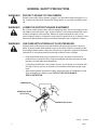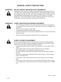
1
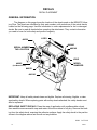
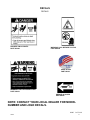
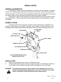
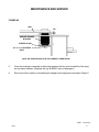
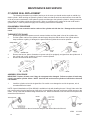
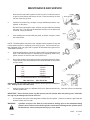
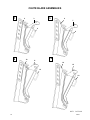
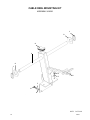
OPERATOR’S AND PARTS MANUAL VP10 VIBRATORY PLOW SERIAL NUMBER: ___________________ MODEL NUMBER: ___________________ 800-456-7100 I www.paladinattachments.com Manual Number: OM654 Part Number: 75554 Rev. 3 503 Gay Street, Delhi, IA 52223, United States of America Copyright © 9283 8-27-14-5 TABLE OF CONTENTS VIBRATORY PLOW PREFACE...........................................................................................................................................................3 SAFETY PRECAUTIONS SAFETY STATEMENTS............................................................................................................................ 5 GENERAL SAFETY PRECAUTIONS.....................................................................................................5-7 EQUIPMENT SAFETY PRECAUTIONS................................................................................................8-9 DECALS DECAL PLACEMENT.............................................................................................................................. 10 DECALS.................................................................................................................................................. 11 INSTALLATION General information...................................................................................................................... 12 nomenclature................................................................................................................................... 12 attaching............................................................................................................................................ 12 detaching............................................................................................................................................13 operating instructions general information...................................................................................................................... 14 direct vibratory plowing (knife blade)............................................................................14-15 vibratory plowing (cable reel mount and chute blade)...........................................15-16 storage...............................................................................................................................................17 lift points........................................................................................................................................... 17 tie down points................................................................................................................................ 17 lubrication................................................................................................................................................18 maintenance AND SERVICE GENERAL MAINTENANCE - every 8 / 40 / 100 / 1000 hours ....................................................... 19 replacing bushings...................................................................................................................20-21 cylinder seal replacement...................................................................................................22-23 troubleshooting.............................................................................................................................24-25 specifications vibratory plow specifications.................................................................................................. 26 bolt torque specifications........................................................................................................ 27 limited warranty.................................................................................................................................. 29 PARTS vibratory plow assemblies....................................................................................................30-33 blade assemblies........................................................................................................................34-35 chute blade assemblies...........................................................................................................36-37 cable reel mounting kit..........................................................................................................38-39 hydraulic assembly...................................................................................................................40-41 hydraulic assembly (hydraulic steering - selector valve).....................................42-43 hydraulic assembly (hydraulic steering - dual auxiliary hydraulics)...............44-45 cylinder assembly.....................................................................................................................46-47 options...........................................................................................................................................48-49 9304 75554 8-27-14-2 1 THIS PAGE IS INTENTIONALLY BLANK 2 75554 PREFACE GENERAL COMMENTS Congratulations on the purchase of your new BRADCO product! This product was carefully designed and manufactured to give you many years of dependable service. Only minor maintenance (such as cleaning and lubricating) is required to keep it in top working condition. Be sure to observe all maintenance procedures and safety precautions in this manual and on any safety decals located on the product and on any equipment on which the attachment is mounted. This manual has been designed to help you do a better, safer job. Read this manual carefully and become familiar with its contents. WARNING! Never let anyone operate this unit without reading the "Safety Precautions" and "Operating Instructions" sections of this manual. Always choose hard, level ground to park the vehicle on and set the brake so the unit cannot roll. Unless noted otherwise, right and left sides are determined from the operator’s control position when facing the attachment. NOTE: The illustrations and data used in this manual were current (according to the information available to us) at the time of printing, however, we reserve the right to redesign and change the attachment as may be necessary without notification. BEFORE OPERATION The primary responsibility for safety with this equipment falls to the operator. Make sure the equipment is operated only by trained individuals that have read and understand this manual. If there is any portion of this manual or function you do not understand, contact your local authorized dealer or the manufacturer to obtain further assistance. Keep this manual available for reference. Provide the manual to any new owners and/or operators. SAFETY ALERT SYMBOL This is the “Safety Alert Symbol” used by this industry. This symbol is used to warn of possible injury. Be sure to read all warnings carefully. They are included for your safety and for the safety of others working with you. SERVICE Use only manufacturer replacement parts. Substitute parts may not meet the required standards. Record the model and serial number of your unit on the cover of this manual. The parts department needs this information to insure that you receive the correct parts. SOUND AND VIBRATION Sound pressure levels and vibration data for this attachment are influenced by many different parameters: some items are listed below (not inclusive): • prime mover type, age, condition, with or without cab enclosure and configuration • operator training, behavior, stress level • job site organization, working material condition, environment Based on the uncertainty of the prime mover, operator, and job site, it is not possible to get precise machine and operator sound pressure levels or vibration levels for this attachment. NOTE: A list of all Paladin Patents can be found at http://www.paladinattachments.com/patents.asp. 10344 75554 7-31-13-4 3 THIS PAGE IS INTENTIONALLY BLANK 4 75554 SAFETY STATEMENTS THIS SYMBOL BY ITSELF OR WITH A WARNING WORD THROUGHOUT THIS MANUAL IS USED TO CALL YOUR ATTENTION TO INSTRUCTIONS INVOLVING YOUR PERSONAL SAFETY OR THE SAFETY OF OTHERS. FAILURE TO FOLLOW THESE INSTRUCTIONS CAN RESULT IN INJURY OR DEATH. DANGER THIS SIGNAL WORD IS USED WHERE SERIOUS INJURY OR DEATH WILL RESULT IF THE INSTRUCTIONS ARE NOT FOLLOWED PROPERLY. WARNING THIS SIGNAL WORD IS USED WHERE SERIOUS INJURY OR DEATH COULD RESULT IF THE INSTRUCTIONS ARE NOT FOLLOWED PROPERLY. CAUTION THIS SIGNAL WORD IS USED WHERE MINOR INJURY COULD RESULT IF THE INSTRUCTIONS ARE NOT FOLLOWED PROPERLY. NOTICE NOTICE INDICATES A PROPERTY DAMAGE MESSAGE. GENERAL SAFETY PRECAUTIONS WARNING! READ MANUAL PRIOR TO INSTALLATION Improper installation, operation, or maintenance of this equipment could result in serious injury or death. Operators and maintenance personnel should read this manual, as well as all manuals related to this equipment and the prime mover thoroughly before beginning installation, operation, or maintenance. FOLLOW ALL SAFETY INSTRUCTIONS IN THIS MANUAL AND THE PRIME MOVER’S MANUAL(S). READ AND UNDERSTAND ALL SAFETY STATEMENTS Read all safety decals and safety statements in all manuals prior to operating or working on this equipment. Know and obey all OSHA regulations, local laws, and other professional guidelines for your operation. Know and follow good work practices when assembling, maintaining, repairing, mounting, removing, or operating this equipment. KNOW YOUR EQUIPMENT Know your equipment’s capabilities, dimensions, and operations before operating. Visually inspect your equipment before you start, and never operate equipment that is not in proper working order with all safety devices intact. Check all hardware to ensure it is tight. Make certain that all locking pins, latches, and connection devices are properly installed and secured. Remove and replace any damaged, fatigued, or excessively worn parts. Make certain all safety decals are in place and are legible. Keep decals clean, and replace them if they become worn or hard to read. 10338 75554 8-16-05 5 GENERAL SAFETY PRECAUTIONS WARNING! PROTECT AGAINST FLYING DEBRIS Always wear proper safety glasses, goggles, or a face shield when driving pins in or out, or when any operation causes dust, flying debris, or any other hazardous material. WARNING! LOWER OR SUPPORT RAISED EQUIPMENT Do not work under raised booms without supporting them. Do not use support material made of concrete blocks, logs, buckets, barrels, or any other material that could suddenly collapse or shift positions. Make sure support material is solid, not decayed, warped, twisted, or tapered. Lower booms to ground level or on blocks. Lower booms and attachments to the ground before leaving the cab or operator’s station. WARNING! USE CARE WITH HYDRAULIC FLUID PRESSURE Hydraulic fluid under pressure can penetrate the skin and cause serious injury or death. Hydraulic leaks under pressure may not be visible. Before connecting or disconnecting hydraulic hoses, read your prime mover’s operator’s manual for detailed instructions on connecting and disconnecting hydraulic hoses or fittings. • Keep unprotected body parts, such as face, eyes, and arms as far away as possible from a suspected leak. Flesh injected with hydraulic fluid may develop gangrene or other permanent disabilities. • If injured by injected fluid, see a doctor at once. If your doctor is not familiar with this type of injury, ask him to research it immediately to determine proper treatment. • Wear safety glasses, protective clothing, and use a piece of cardboard or wood when searching for hydraulic leaks. DO NOT USE YOUR HANDS! SEE ILLUSTRATION. CARDBOARD HYDRAULIC HOSE OR FITTING MAGNIFYING GLASS 10339 6 8-16-05 75554 GENERAL SAFETY PRECAUTIONS WARNING! DO NOT MODIFY MACHINE OR ATTACHMENTS Modifications may weaken the integrity of the attachment and may impair the function, safety, life, and performance of the attachment. When making repairs, use only the manufacturer’s genuine parts, following authorized instructions. Other parts may be substandard in fit and quality. Never modify any ROPS (Roll Over Protection Structure) or FOPS (Falling Object Protective Structure) equipment or device. Any modifications must be authorized in writing by the manufacturer. WARNING! SAFELY MAINTAIN AND REPAIR EQUIPMENT • Do not wear loose clothing or any accessories that can catch in moving parts. If you have long hair, cover or secure it so that it does not become entangled in the equipment. • Work on a level surface in a well-lit area. • Use properly grounded electrical outlets and tools. • Use the correct tools for the job at hand. Make sure they are in good condition for the task required. • Wear the protective equipment specified by the tool manufacturer. SAFELY OPERATE EQUIPMENT Do not operate equipment until you are completely trained by a qualified operator in how to use the controls, know its capabilities, dimensions, and all safety requirements. See your machine’s manual for these instructions. • Keep all step plates, grab bars, pedals, and controls free of dirt, grease, debris, and oil. • Never allow anyone to be around the equipment when it is operating. • Do not allow riders on the attachment or the prime mover. • Do not operate the equipment from anywhere other than the correct operator’s position. • Never leave equipment unattended with the engine running, or with this attachment in a raised position. • Do not alter or remove any safety feature from the prime mover or this attachment. • Know your work site safety rules as well as traffic rules and flow. When in doubt on any safety issue, contact your supervisor or safety coordinator for an explanation. 10340 75554 8-16-05 7 EQUIPMENT SAFETY PRECAUTIONS WARNING! KNOW WHERE UTILITIES ARE Observe overhead electrical and other utility lines. Be sure equipment will clear them. When digging, call your local utilities for location of buried utility lines, gas, water, and sewer, as well as any other hazard you may encounter. WARNING! EXPOSURE TO RESPIRABLE CRYSTALLINE SILICA DUST ALONG WITH OTHER HAZARDOUS DUSTS MAY CAUSE SERIOUS OR FATAL RESPIRATORY DISEASE. This attachment is designed to plane (mill) rock, concrete and asphalt, causing high levels of dust. It is recommended to use dust suppression, dust collection and if necessary personal protective equipment during the operation of the planer or of any attachment that may cause high levels of dust. WARNING! REMOVE PAINT BEFORE WELDING OR HEATING Hazardous fumes/dust can be generated when paint is heated by welding, soldering or using a torch. Do all work outside or in a well ventilated area and dispose of paint and solvent properly. Remove paint before welding or heating. When sanding or grinding paint, avoid breathing the dust. Wear an approved respirator. If you use solvent or paint stripper, remove stripper with soap and water before welding. Remove solvent or paint stripper containers and other flammable material from area. Allow fumes to disperse at least 15 minutes before welding or heating. WARNING! END OF LIFE DISPOSAL At the completion of the useful life of the unit, drain all fluids and dismantle by separating the different materials (rubber, steel, plastic, etc.). Follow all federal, state and local regulations for recycling and disposal of the fluid and components. OPERATING THE ATTACHMENT • • • • • Block off work area from bystanders, livestock, etc. Operate only from the operator’s station. Reduce speed when driving over rough terrain, on a slope, or turning, to avoid overturning the vehicle. An operator must not use drugs or alcohol, which can change his or her alertness or coordination. An operator taking prescription or over-the-counter drugs should seek medical advice on whether or not he or she can safely operate equipment. Before exiting the prime mover, lower the attachment to the ground, turn off the prime mover’s engine, remove the key and apply the brakes. TRANSPORTING THE ATTACHMENT • • • • Travel only with the attachment in a safe transport position to prevent uncontrolled movement. Drive slowly over rough ground and on slopes. When driving on public roads use safety lights, reflectors, Slow Moving Vehicle signs etc., to prevent accidents. Check local government regulations that may affect you. Do not drive close to ditches, excavations, etc., cave in could result. Do not smoke when refueling the prime mover. Allow room in the fuel tank for expansion. Wipe up any spilled fuel. Secure cap tightly when done. 8917 8 8-27-14-2 75554 EQUIPMENT SAFETY PRECAUTIONS MAINTAINING THE ATTACHMENT • • • • • Before performing maintenance, lower the attachment to the ground, turn off the engine, remove the key and apply the brakes. Never perform any work on the attachment unless you are authorized and qualified to do so. Always read the operator service manual’s before any repair is made. After completing maintenance or repair, check for correct functioning of the attachment. If not functioning properly, always tag “DO NOT OPERATE” until all problems are corrected. Worn, damaged, or illegible safety decals must be replaced. New safety decals can be ordered from BRADCO. Never make hydraulic repairs while the system is under pressure. Serious personal injury or death could result. Never work under a raised attachment. 8918 75554 8-27-14-2 9 DECALS DECAL PLACEMENT GENERAL INFORMATION The diagram on this page shows the location of the decals used on the BRADCO Vibratory Plow. The decals are identified by their part numbers, with reductions of the actual decals located on the following page. Use this information to order replacements for lost or damaged decals. Be sure to read all decals before operating the attachment. They contain information you need to know for both safety and product longevity. LOGO #4338 SERIAL NUMBER TAG LOCATION #40440 #40149 LOGO MODEL NUMB3ER #4085 (On Mount Pivot) #40151 #40149 IMPORTANT: Keep all safety decals clean and legible. Replace all missing, illegible, or damaged safety decals. When replacing parts with safety decals attached, the safety decals must also be replaced. REPLACING SAFETY DECALS: Clean the area of application with nonflammable solvent, then wash the same area with soap and water. Allow the surface to fully dry. Remove the backing from the safety decal, exposing the adhesive surface. Apply the safety decal to the position shown in the diagram above and smooth out any bubbles. 9284 10 8-27-14-2 75554 DECALS DECALS DANGER! PINCH POINTS PART #40149 WARNING! CALL BEFORE YOU DIG PART #40440 MADE IN USA PART #4338 40 WARNING! HIGH PRESSURE FLUID PART #40151 GREASE 40 HOURS PART #4085 NOTE: CONTACT YOUR LOCAL DEALER FOR MODEL NUMBER AND LOGO DECALS. 9285 75554 8-27-14-2 11 INSTALLATION GENERAL INFORMATION The BRADCO Vibratory Plow was designed to be easy to use and maintain. It is operatored by your loader auxiliary hydraulics and mounts to the toolbar / quick attach mechanism for easy mounting. The Vibratory Plow was shipped complete with the appropriate mounting for your specific prime mover and with the hydraulic hoses and couplers installed. Remember to read all safety warnings, decals and operating instructions before operating the attachment. If there is any portion of this manual that you do not understand, contact your dealer. NOMENCLATURE Throughout this manual, reference is made to various attachment components. The purpose of this section is to acquaint you with the various names of these components. This knowledge will be helpful when reading through the manual or when ordering service parts. REAR FRAME "SHAKER BOX" DRIVE TOP RIGHT LINK MOUNTING PLATE FRONT FRAME HYDRAULIC MOTOR BOTTOM RIGHT LINK PRESSURE FOOT CHUTE BLADE TOP COVER AND MOTOR COVER REMOVED FOR CLARITY INSTALLATION 1. 2. Remove any attachment from the front of the prime mover. Following all standard safety practices and the instructions for installing an attachment in your prime mover operator’s manual, install the attachment onto your loader. WARNING! To avoid serious personal injury, make sure the attachment is securely latched to the attachment mechanism of your unit. Failure to do so could result in separation of the attachment from the prime mover. 9305 12 8-27-14-2 75554 INSTALLATION 3. 4. 5. 6. 7. Lower the unit to the ground and relieve pressure to the auxiliary hydraulic lines. Following the safety shut down procedure for your prime mover, shut down and exit the prime mover. After making sure that the hydraulic couplers are free from any foreign material or contaminants, connect the couplers to the auxiliary hydraulic system of your prime mover. Following the standard start up procedure for your prime mover, start the loader and run all cylinders on the attachment to purge any air from the system. Check for proper hydraulic connection, hose routing and hose length. Attachment installation is complete. DETACHING On firm level ground, remove the coulter wheel and then remove the blade and reinstall it in the transport position. Lower the boom arms completely down on the frame until the attachment is level and approximately 2" off the ground. Turn off the engine. Move the control levers back and forth to relieve pressure in line. Disconnect couplers. NOTE: Connect couplers together or install caps to prevent contaminants from entering the hydraulic system. Follow your prime mover operator's manual for detaching (removing) an attachment. Store hoses off the ground to help prevent damage. NOTE: Frequent lubrication of grease fittings on the cylinder and pivot tube on the mount with a multi-purpose grease will greatly increase life of the product. 9288 75554 8-27-14-2 13 OPERATING INSTRUCTIONS VIBRATORY PLOW GENERAL INFORMATION Simplicity of operation is one of the key features of the Vibratory Plow. The basic vibratory plow itself has no controls, and only one grease fitting. Since the vibratory plow mounts to the toolbar / attachment plate of the loader, it is important to be familiar with, and know the controls on the loader. Such knowledge is crucial for safe, efficient operation of equipment. Read your loader owner's manual for information regarding operation before attempting to use the attachment. Take the time to learn how they operate now. The Vibratory Plow is relatively simple to use, and with the help of the information in this section and a little practice you should become proficient in its operation in no time. Observe the following points to obtain the best results with the least amount of wear on the machine. Read the "Safety Precautions" section of this manual before you begin. See Section "B". CAUTION! Operate the vibratory plow only from the operator's station. Pay attention to the job at hand. Be alert to the possibility of others in the work area. Always CALL BEFORE YOU DIG. Locate all underground utilities before you begin. Never let anyone perform maintenance on the machine while it is running. The Vibratory Plow minimizes turf damage during installation and greatly reduces the time spent on installing pipe for irrigation and lawn sprinkler systems, water and natural gas pipe, telephone and television cable, and wire for "invisible" dog fences. There are various options available for the vibratory plow. There are four different knife blades which utilize the pull bullet assembly, the cable pull assembly, and/or the pipe bullet assembly. These attach to the clevis on the knife blade with a 3/8" grade 8 bolt (not included). Also available for the vibratory plow is a cable reel mount that mounts two 24" maximum diameter cable spools and utilizes the four optional chute blades that accommodate cable up to 1/2" in diameter. There are two methods of installation: Direct Vibratory Plowing with the standard knife blade, and Vibratory Plowing with the optional chute blade and cable reel mounting. DIRECT VIBRATORY PLOWING (KNIFE BLADE) Using the direct vibratory plowing method is convenient, fast, and requires a minimum of restoration work after the installation has been completed. This method is usually limited to short runs, where tension on the cable is low enough to prevent damage to the cable. With this method, the cable being pulled is actually pulled through the earth along the entire route. Therefore, this method is best used only for conduit, pipe, or cable-in-conduit unless a bullet assembly (at least twice the size of the cable or pipe) is used in the installation process, which will open up the ground sufficiently to pull the cable through with a minimum of pulling tension. 9289 14 8-28-14-2 75554 OPERATING INSTRUCTIONS VIBRATORY PLOW DIRECT VIBRATORY PLOWING (Continued) WARNING! Always CALL BEFORE YOU DIG. Locate all underground utilities before you begin. To begin, dig a starter trench and lower the blade/bullet combination into the trench to the desired depth with the cable attached to the bullet or cable pull. Continue to plow for several feet past the destination pedestal location to allow excess cable for connecting and splicing. At this point, stop the vibratory plow, lift the blade carefully from the ground, and disconnect the cable from the blade. Inspect the cable for any damage that may have occurred during the installation process. CABLE REEL VIBRATORY PLOW STARTER TRENCH PULL BULLET CABLE Cable Protection When the plowing section has been completed, remove any damage from the end of the cable and make sure approximately 40 inches of undamaged cable remain to facilitate connecting and splicing. Install plastic end caps to protect from moisture. A hose clamp should be installed on flooded cable to prevent jacket shinkback. NOTE: Be sure to observe the minimum bending radius restrictions for the size of cable/ pipe being installed. VIBRATORY PLOWING (CABLE REEL MOUNT & CHUTE BLADE) Using the vibratory plowing method of installation is often chosen for its efficiency and lack of required restoration work. But this method is limited in the size of cable or cable-in-conduit by the chute blade, which will accommodate a cable of up to 1/2" in diameter. Cable routes that intersect roads, driveways, or sidewalks should always be avoided. With this method, the cable is not pulled through the earth, so the amount of tension on the cable is minimal. Unlike the direct plowing method where the payout reel is stationary, with the vibratory plowing method the payout reel is mounted onto the vibratory plow using the optional cable reel mount. The cable is played out over the unit and into the cable guide guide chute attached to the blade. 9290 75554 8-28-14-2 15 OPERATING INSTRUCTIONS VIBRATORY PLOW VIBRATORY PLOWING (Continued) WARNING! Always CALL BEFORE YOU DIG. Locate all underground utilities before you begin. To begin, dig a starter trench. The cable or cable-in-conduit should play off the top of the reel, through the cable guide and over the unit. Be sure to minimize rubbing or scraping which could cause damage to the cable. Remove the chute from the blade and form and position the cable down along the inside of the blade. Place the chute into position, and lock in place using the safety snap pin. (It is recommended that you apply a lubricant to the inside of the chute to reduce friction and tension.) Pull out a sufficient amount of cable from the reel and through the starter trench. The blade can be lowered into the starter trench while a crew member holds the cable for approximately the first 50 feet of the operation, so the loose end is not inadvertently pulled along. A layer of soil may be applied over the cable in the starter trench to help hold it in place. NOTE: The cable should never be forcibly pushed into the blade chute. Continue to plow for several feet past the destination pedestal location to allow excess cable for connecting and splicing. At this point, stop the vibratory plow and remove the chute from the blade and carefully remove the cable. When the cable is free, the blade can be moved forward and lifted out of the ground. Inspect the cable for any damage that may have occurred during the installation process. VIBRATORY PLOW CABLE REEL CABLE CHUTE BLADE CABLE STARTER TRENCH Cable Protection When the plowing section has been completed, remove any damage from the end of the cable and make sure approximately 40 inches of undamaged cable remain to facilitate connecting and splicing. Install plastic end caps to protect from moisture. A hose clamp should be installed on flooded cable to prevent jacket shinkback. NOTE: Be sure to observe the minimum bending radius restrictions for the size of cable/ pipe being installed. 9291 16 8-28-14-2 75554 OPERATING INSTRUCTIONS VIBRATORY PLOW STORAGE: • Clean the unit thoroughly, removing all mud, dirt, and grease. • Inspect for visible signs of wear, breakage, or damage. Order any parts required and make the necessary repairs to avoid delays upon removal from storage. • Tighten loose nuts, capscrews and hydraulic connections. • Coat exposed portions of the cylinder rods with grease. • Lubricate grease fittings. • Seal hydraulic system from contaminants and secure all hydraulic hoses off the ground to help prevent damage. • Replace decals that are damaged or in unreadable condition. • Store unit in a dry and protected place. Leaving the unit outside will materially shorten its life. Additional Precautions for Long term Storage: • Touch up all unpainted surfaces with paint to prevent rust. Removal from Storage: • • • • Remove cover. Wash unit and replace any damaged and/or missing parts. Lubricate grease fittings. Check hydraulic hoses for damage and replace as necessary. LIFT POINTS Lifting points are identified by a lifting decals where required. Lifting at other points is unsafe and can damage attachment. Do not attach lifting accessories around cylinders or in any way that may damage hoses or hydraulic components. • Attach lifting accessories to unit at recommended lifting points. • Bring lifting accessories together to a central lifting point. • Lift gradually, maintaining the equilibrium of the unit. WARNING! Use lifting accessories (chains, slings, ropes, shackles and etc.) that are capable of supporting the size and weight of your attachment. Secure all lifting accessories in such a way to prevent unintended disengagement. Failure to do so could result in the attachment falling and causing serious personal injury or death. TIE DOWN POINTS Tie down points are identified by tie down decals where required. Securing to trailer at other points is unsafe and can damage attachment. Do not attach tie down accessories around cylinders or in any way that may damage hoses or hydraulic components. • Attach tie down accessories to unit as recommended. • Check unit stability before transporting. WARNING!Verify that all tie down accessories (chains, slings, ropes, shackles and etc.) are capable of maintaining attachment stability during transporting and are attached in such a way to prevent unintended disengagement or shifting of the unit. Failure to do so could result in serious personal injury or death. 12868 8-28-14 75554 17 LUBRICATION VIBRATORY PLOW GENERAL INFORMATION Economical and efficient operation of any machine is dependent upon regular and proper lubrication All parts provided with grease fittings should be lubricated every 40 hours as indicated. If any grease fittings are missing, replace them immediately. Clean all fittings thoroughly before using grease gun. IMPORTANT: Avoid excessive greasing. Dirt collects on exposed grease and greatly increases wear. After greasing, wipe off excessive grease from fittings. GEARBOX (SHAKER BOX) The oil level in the gear box should be checked after every 40 hours of operation. Proper level of lubricant in the gear box is approximately 1.4 quarts. Fill as necessary with #90 transmission oil. The gear box is a sealed unit. If there is any sign of oil leaks please contact your nearest BRADCO dealer before carrying out any repairs. The gear box oil should be changed after the first 100 hours of operation and then every 1000 hours thereafter. TO CHECK OIL LEVEL: Be sure to park the unit on a level surface and remove the motor cover. Remove the check plug on the gear box (shaker box). Oil should be level with the check plug hole. Add oil as necessary. TO ADD OIL: Remove the top cover. Remove the filler plug on the top of the gear box and add up to the full point (check plug). TO CHANGE OIL: 1. Park the unit on a level surface. 2. Remove the motor cover. 3. Position a drain pan under the unit and remove the drain plug. 4. Once the oil is drained reinstall the drain plug. 5. Remove the top cover to gain access to the filler plug. Add approximately 1.4 quarts of #90 weight transmission oil. 6. Check oil level and add as necessary. FILL PLUG GEAR BOX (SHAKER BOX) CHECK PLUG DRAIN PLUG 9292 18 8-28-14-2 75554 MAINTENANCE AND SERVICE GENERAL INFORMATION Regular maintenance is the key to long equipment life and safe operation. Maintenance requirements have been reduced to an absolute minimum. However, it is very important that these maintenance functions be performed as described. WARNING! When replacing parts use only factory approved replacement parts. Manufacturer will not claim responsibility for use of unapproved parts or accessories and/or other damages as a result of their use. PROCEDURE Check all hardware and tighten, if necessary. See Bolt Torque Specifications. Check for missing hardware and replace with approved replacement parts. Check hydraulic system for hydraulic oil leaks. Visually inspect the machine for worn parts or cracked welds and replace as necessary. Check for missing or illegible Safety / Warning Decals. Lubricate all grease fittings. Check oil in gear box (shaker box). Change oil in gear box after the first 100 hours break in period. DAILY EVERY 40 HOURS 100 HOURS 1000 HOURS Change oil in gear box. WARNING! Escaping fluid under pressure can have sufficient force to penetrate the skin, causing serious personal injury. Fluid escaping from a very small hole can be almost invisible. Use a piece of cardboard or wood, rather than hands to search for suspected leaks. Keep unprotected body parts, such as face, eyes, and arms as far away as possible from a suspected leak. Flesh injected with hydraulic fluid may develop gangrene or other permanent disabilities. If injured by injected fluid, see a doctor at once. If your doctor is not familiar with this type of injury, ask him to research it immediately to determine proper treatment. 9293 75554 8-28-14-2 19 MAINTENANCE AND SERVICE REPLACING BUSHINGS Due to the constant shaking motion of the vibratory plow the square bonded bushings will eventually become worn and require replacement. An installation kit (#19856) can be purchased from your BRADCO dealer to assist in the installation process. 1. Determine which bushing needs replaced and remove the necessary link by first removing the two .38" UNC X .75" capscrews (#1953) and keepers (#17862) that are securing it to the unit. 2. Locate the bushing (A-H) being replaced in Figure #1 and note the keyway orientation. The correct keyway orientation is critical to the final assembly. FIGURE #1 C A A E G D C G 45° H 45° 45° 45° 45° 45° E B B F H D F 3. Remove the worn bushing. 4. Lubricate the bushing and the bushing socket lightly with P-80 rubber emulsion lubricant or water. Position the bushing on the outside of the bushing socket and press into place. NOTE: BE SURE TO INSTALL THE BUSHING WITH THE CORRECT KEYWAY ORIENTATION. (SEE FIGURE #1) Note: The bushing should extend out .125" (1/8") from the outside of the socket on both sides. See Figure #2 9294 20 8-28-14-2 75554 MAINTENANCE AND SERVICE FIGURE #2 LINK .125" SQUARE BONDED BUSHING KEEPER #17862 .38" X .75" CAPSCREW #1953 NOTE: BE SURE KEYWAY IS IN THE CORRECT ORIENTATION. 5. Once the bushing is centered in the socket position the key and re-install the link using an anti-seize lubricant. (Replace the key #18695 if worn or damaged.) 6. Secure the link in place by reinstalling the keepers and capscrews removed in Step #1. 9295 75554 8-28-14-2 21 MAINTENANCE AND SERVICE CYLINDER SEAL REPLACEMENT The following information is provided to assist you in the event you should need to repair or rebuild a hydraulic cylinder. When working on hydraulic cylinders, make sure that the work area and tools are clean and free of dirt to prevent contamination of the hydraulic system and damage to the hydraulic cylinders. Always protect the active part of the cylinder rod (the chrome section). Nicks or scratches on the surface of the rod could result in cylinder failure. Clean all parts thoroughly with a cleaning solvent before reassembly. DISASSEMBLY PROCEDURE IMPORTANT: Do not contact the active surface of the cylinder rod with the vise. Damage to the rod could result. THREADED TYPE GLAND Rotate the gland with a spanner wrench counterclockwise until the gland is free of the cylinder tube. Pull the cylinder rod from the cylinder tube and inspect the piston and the bore of the cylinder tube for deep scratches or galling. If damaged, the piston AND the cylinder tube must be replaced. 1. 2. 3. Remove the hex nut, piston, flat washer or spacer tube (if so equipped), and gland from the cylinder rod. If the cylinder rod is rusty, scratched, or bent, it must be replaced. Remove and discard all the old seals. 4. ASSEMBLY PROCEDURE IMPORTANT: Replace all seals even if they do not appear to be damaged. Failure to replace all seals may result in premature cylinder failure. NOTE: Seal kits will service most cylinders of similar bore size and rod diameter. 1. Install the cylinder rod seal in the gland first. Be careful not to damage the seal in the process, as it is somewhat difficult to install. NOTE: A special installation tool (Part #65349) is available to help with installing the seal. Simply fit the end of the tool over the seal so that the large prong of the tool is on the outside of the seal, and the two smaller prongs on the inside. The lip of the seal should be facing towards the tool. Rotate the handles on the tool around to wrap the seal around the end of the tool. Rotate the handles on the tool around to wrap the seal around the end of the tool. 10356 22 10-13-05 75554 MAINTENANCE AND SERVICE Now insert the seal into the gland from the inner end. Position the seal in its groove, and release and remove the tool. Press the seal into its seat the rest of the way by hand. 2. Install the new piston ring, rod wiper, O-rings and backup washers, if applicable, on the piston. Be careful not to damage the seals. Caution must be used when installing the piston ring. The ring must be stretched carefully over the piston with a smooth, round, pointed tool. 3. After installing the rod seal inside the gland, as shown in step #1, install the external seal. NOTE: Threaded glands may have been equipped with a separate O-ring and backup washer system or a polypak (all in one) type seal. Current seal kits contain a polypak (all in one) type seal to replace the discarded seal types on ALL THREADED GLANDS. 4. Slide the gland onto the cylinder rod, being careful not to damage the rod wiper. Then install the spacer, or flat washer (if so equipped), small o-ring, piston, and hex nut onto the end of the cylinder rod. 5. Secure the cylinder rod (mounting end) in a vise with a support at its center. Torque the nut to the amount shown for the thread diameter of the cylinder rod (see chart). Thread Diameter 7/8" *1" 1-1/8" 1-1/4" 1-3/8" POUNDS - FEET 150-200 230-325 350-480 490-670 670-900 * 1" Thread Diameter WITH 1.25" Rod Diameter Min. 230 ft. lbs. Max. 250 ft. lbs. IMPORTANT: Do not contact the active surface of the cylinder rod with the vise. Damage to the rod could result. 6. Apply a lubricant (such as Lubriplate #105) to the piston and teflon ring. Insert the cylinder rod assembly into the cylinder tube. IMPORTANT: Ensure that the piston ring fits squarely into the cylinder tube and piston groove, otherwise the ring may be damaged and a leak will occur. 7. Use a spanner wrench to rotate the gland clockwise into the cylinder. Continue to rotate the gland with the spanner wrench until it is tight. WARNING! Cylinders serviced in the field are to be tested for leakage prior to the attachment being placed in work. Failure to test rebuilt cylinders could result in damage to the cylinder and/or the attachment, cause severe personal injury or even death. 10357 75554 10-13-05 23 TROUBLESHOOTING PROBLEM POSSIBLE CAUSE POSSIBLE SOLUTION External leaking. Cylinder seals damaged. Replace cylinder seals. Broken or loose hydraulic fittings or line. Check for leaks and repair or replace. Motor gasket damaged. Replace. Loader auxiliary hydraulics not engaged. Refer to loader operator's manual. Inadequate hydraulic flow from loader. Check hydraulic flow to plow. Low oil supply. Add oil. Couplers not engaged. Engage couplers. Air in hydraulic lines. Activate system until air is purged from system. Broken hose. Replace damaged hose. Obstructions in hydraulic lines. Remove obstructions and replace if necessary. Loose or damaged hydraulic connection. Tighten or replace fittings. Motor damaged or seal blown. Call Bradco's service department for instructions. Ground speed too fast. Reduce ground speed. Broken or leaking hydraulic lines. Replace broken hose and check for leaks. Oil leaking past cylinder packings. Replace cylinder seals. (Hydraulic Steering Option) Vibratory Plow not vibrating. Vibratory plow fails to maintain angle. (Hydraulic Steering Option) 9296 24 8-28-14-2 75554 TROUBLESHOOTING PROBLEM POSSIBLE CAUSE POSSIBLE SOLUTION Vibratory Plow angles too slowly. Cold oil. Warm oil with engine at idle. Engine speed too slow. Open Throttle. Oil leaking past cylinder packings. Replace cylinder seals. Ground speed too slow. Adjust ground speed. Bushing(s) worn or damaged. Replace as necessary. Turning radius too sharp for ground speed. Adjust the hydraulic angle to increase turning radius and adjust travel speed as required. Vibratory plow stalls Ground speed too fast. Adjust ground speed. Excessive vibration transferred to loader and mounting bracket. Ground speed too fast for ground condition. Adjust ground speed. Underground obstruction. Locate and remove obstruction or reroute cable. (Hydraulic Steering Option) Excessive noise. 9297 75554 8-28-14-2 25 SPECIFICATIONS VIBRATORY PLOW B C A SPECIFICATIONS AND DESIGN ARE SUBJECT TO CHANGE WITHOUT NOTICE AND WITHOUT LIABILITY THEREFOR. SPECIFICATIONS DESCRIPTIONSPECIFICATION A. Overall Height............................................................................. 27.1" B. Overall Width.............................................................................. 24.5" C. Overall Length............................................................................ 35.8" Flow Requirements (GPM)......................................................................8-14 Operating Pressure (PSI)...................................................................1500-2500 Weight (LBS)......................................................................................... 510# NOTE: Dimensions DO NOT include blade or coulter wheel. 9191 26 8-28-14-2 75554 BOLT TORQUE SPECIFICATIONS GENERAL TORQUE SPECIFICATION TABLES Use the following charts when determining bolt torque specifications when special torques are not given. Always use grade 5 or better when replacing bolts. SAE BOLT TORQUE SPECIFICATIONS NOTE: The following torque values are for use with extreme pressure lubricants, plating or hard washer applications Increase torque 15% when using hardware that is unplated and either dry or lubricated with engine oil. SAE GRADE 5 TORQUE Bolt Size Pounds Feet Newton-Meters SAE GRADE 8 TORQUE Pounds Feet UNC Newton-Meters Inches Millimeters UNC UNF UNC UNF UNF UNC UNF 1/4 5/16 6.35 7.94 8 14 9 17 11 19 12 23 10 20 13 25 14 27 18 34 62 3/8 9.53 30 36 41 49 38 46 52 7/16 11.11 46 54 62 73 60 71 81 96 1/2 12.70 68 82 92 111 94 112 127 152 9/16 14.29 94 112 127 136 163 184 221 5/8 15.88 128 153 174 152 207 187 224 254 304 3/4 19.05 230 275 312 373 323 395 438 536 7/8 22.23 340 408 461 553 510 612 691 830 1 25.40 493 592 668 803 765 918 1037 1245 1-1/8 25.58 680 748 922 1014 1088 1224 1475 1660 1-1/4 31.75 952 1054 1291 1429 1547 1700 2097 2305 1-3/8 34.93 1241 1428 1683 1936 2023 2312 2743 3135 1-1/2 38.10 1649 1870 2236 2535 2686 3026 3642 4103 Bolt head identification marks as per grade. NOTE: Manufacturing Marks Will Vary METRIC BOLT TORQUE SPECIFICATIONS Bolt head identification marks as per grade. NOTE: The following torque values are for use with metric hardware that is unplated and either dry or lubricated with engine oil. Reduce torque 15% when using hardware that has extreme pressure lubricants, plating or hard washer applications. Size of Bolt Grade No. Pitch (mm) Pounds Feet Newton-Meters Pitch (mm) Pounds Feet Newton-Meters M6 5.6 8.8 10.9 1.0 3.6-5.8 5.8-.4 7.2-10 4.9-7.9 7.9-12.7 9.8-13.6 - - - M8 5.6 8.8 10.9 1.25 7.2-14 17-22 20-26 9.8-19 23-29.8 27.1-35.2 1.0 12-17 19-27 22-31 16.3-23 25.7-36.6 29.8-42 M10 5.6 8.8 10.9 1.5 20-25 34-40 38-46 27.1-33.9 46.1-54.2 51.5-62.3 1.25 20-29 35-47 40-52 27.1-39.3 47.4-63.7 54.2-70.5 M12 5.6 8.8 10.9 1.75 28-34 51-59 57-66 37.9-46.1 69.1-79.9 77.2-89.4 1.25 31-41 56-68 62-75 42-55.6 75.9-92.1 84-101.6 M14 5.6 8.8 10.9 2.0 49-56 81-93 96-109 66.4-75.9 109.8-126 130.1-147.7 1.5 52-64 90-106 107-124 70.5-86.7 122-143.6 145-168 M16 5.6 8.8 10.9 2.0 67-77 116-130 129-145 90.8-104.3 157.2-176.2 174.8-196.5 1.5 69-83 120-138 140-158 93.5-112.5 162.6-187 189.7-214.1 M18 5.6 8.8 10.9 2.0 88-100 150-168 175-194 119.2-136 203.3-227.6 237.1-262.9 1.5 100-117 177-199 202-231 136-158.5 239.8-269.6 273.7-313 M20 5.6 8.8 10.9 2.5 108-130 186-205 213-249 146.3-176.2 252-277.8 288.6-337.4 1.5 132-150 206-242 246-289 178.9-203.3 279.1-327.9 333.3-391.6 75554 10360 3-20-08-3 27 THIS PAGE IS INTENTIONALLY BLANK 28 75554 Limited Warranty Except for the Excluded Products as described below, all new products are warranted to be free from defects in material and/or workmanship during the Warranty Period, in accordance with and subject to the terms and conditions of this Limited Warranty. 1. Excluded Products. The following products are excluded from this Limited Warranty: (a) Any cable, part that engages with the ground (i.e. sprockets), digging chain, bearing, teeth, tamping and/or demolition head, blade cutting edge, pilot bit, auger teeth and broom brush that either constitutes or is part of a product. (b) Any product, merchandise or component that, in the opinion of Paladin Light Construction1, has been (i) misused; (ii) modified in any unauthorized manner; (iii) altered; (iv) damaged; (v) involved in an accident; or (vi) repaired using parts not obtained through Paladin Light Construction. 2. Warranty Period. The Limited Warranty is provided only to those defects that occur during the Warranty Period, which is the period that begins on the first to occur of: (i) the date of initial purchase by an end-user, (ii) the date the product is first leased or rented, or (iii) the date that is six (6) months after the date of shipment by Paladin Light Construction as evidenced by the invoiced shipment date (the “Commencement Date”) and ends on the date that is twelve (12) months after the Commencement Date. 3. Terms and Conditions of Limited Warranty. The following terms and conditions apply to the Limited Warranty hereby provided: (a) the product. Option to Repair or Replace. Paladin Light Construction shall have the option to repair or replace (b) Timely Repair and Notice. In order to obtain the Limited Warranty, (i) the product must be repaired within thirty (30) days from the date of failure, and (ii) a claim under the warranty must be submitted to Paladin Light Construction in writing within thirty (30) days from the date of repair. (c) Return of Defective Part or Product. If requested by Paladin Light Construction, the alleged defective part or product shall be shipped to Paladin Light Construction at its manufacturing facility or other location specified by Paladin Light Construction, with freight PRE-PAID by the claimant, to allow Paladin Light Construction to inspect the part or product. Claims that fail to comply with any of the above terms and conditions shall be denied. LIMITATIONS AND EXCLUSIONS. THIS LIMITED WARRANTY IS IN LIEU OF ALL OTHER WARRANTIES, EXPRESS OR IMPLIED, INCLUDING WITHOUT LIMITATION THE WARRANTIES OF MERCHANTABILITY, FITNESS FOR A PARTICULAR PURPOSE AND ANY WARRANTY BASED ON A COURSE OF DEALING OR USAGE OF TRADE. IN NO EVENT SHALL PALADIN LIGHT CONSTRUCTION BE LIABLE FOR CONSEQUENTIAL OR SPECIAL DAMAGES. IN NO EVENT SHALL PALADIN LIGHT CONSTRUCTION BE LIABLE FOR ANY LOSS OR CLAIM IN AN AMOUNT IN EXCESS OF THE PURCHASE PRICE, OR, AT THE OPTION OF PALADIN LIGHT CONSTRUCTION, THE REPAIR OR REPLACEMENT, OF THE PARTICULAR PRODUCT ON WHICH ANY CLAIM OF LOSS OR DAMAGE IS BASED. THIS LIMITATION OF LIABILITY APPLIES IRRESPECTIVE OF WHETHER THE CLAIM IS BASED ON BREACH OF CONTRACT, BREACH OF WARRANTY, NEGLIGENCE OR OTHER CAUSE AND WHETHER THE ALLEGED DEFECT IS DISCOVERABLE OR LATENT. Attachment Technologies Inc., a subsidiary of Paladin Brands Holding, Inc. (PBHI) is referred to herein as Paladin Light Construction. February 10, 2010 1 75554 29 VIBRATORY PLOW ASSEMBLY ASSEMBLIES #19000 & #19693 3 1 4 5 6 10 9 8 DIAGRAM 1 OF 2 7 2 12 13 15 22 25 11 24 14 23 14 18 21 9 16 20 18 17 19 9265 30 8-27-14-2 75554 VIBRATORY PLOW ASSEMBLY ASSEMBLIES #19000 & #19693 REQ’D PART NO. 1 2 3 4 5 2 2 1 1 ** - 1 1 10085 1504 19645 19314 19814 19815 22532 1512 6 7 8 9 10 1 1 1 8 1 1502 1020 2000515 1961 17864 Lock Washer .31” UNC X .50” Hex Capscrew Drive .38” UNC X .50” Flange Head Capscrew Top Cover 11 12 13 14 15 4 8 9 8 1 10086 1646 1841 18695 18692 .50” UNC X 2.25” Hex Capscrew Grade 8 .50” Hard Flat Washer .50” UNC Deformed Oval Lock Nut Key Top Right Link 1 1 8 2 3 19285 17857 18805 17866 6626 Motor Cover Bottom Right Link Square Bonded Bushing Blade Pin Klik Pin ITEM 16 17 18 19 20 21 22 23 24 25 1 1 8 9 1 17859 17856 17862 1953 2006901 LIST 1 OF 2 DESCRIPTION .44” UNC X 1.25” Sockethead Capscrew .44” Lock Washer Hydraulic Motor 7.5 - 11 GPM (Assembly #19693) Hydraulic Motor 9.5 - 14 GPM (Assembly #19000) Replacement Motor Seal Kit Replacement Motor Shaft Key Motor Gasket Flat Washer Bottom Left Link Top Left Link Keeper .38” UNC X .75” Tapping Screw Front Frame ** Field replacement of the internal motor seals voids warranty. 9266 75554 8-27-14-4 31 VIBRATORY PLOW ASSEMBLY ASSEMBLIES #19000 & #19693 DIAGRAM 2 OF 2 27 28 24 29 30 26 31 37 32 31 18 33 34 35 18 36 13 38 14 39 40 41 35 42 47 48 20 44 43 45 45 49 46 9267 32 8-27-14-2 75554 VIBRATORY PLOW ASSEMBLY ASSEMBLIES #19000 & #19693 ITEM REQ’D PART NO. DESCRIPTION 13 14 18 20 24 9 8 8 3 9 1841 18695 18805 6626 1953 .50” UNC Deformed Oval Lock Nut Key Square Bonded Bushing Klik Pin .38” UNC X .75” Tapping Screw 1 2 2 1 1 18875 6612 57462 6616 18821 Main Pivot Pin Snap Ring Thrust Washer Grease Fitting Spring Rod 31 32 33 34 35 2 1 1 1 5 100212 18818 1518 1534 1780 Spring Pivot Plate .75” Flat Washer .75” UNC Nylock Nut .50” UNC X 1.25” Hex Capscrew - Grade 8 36 37 38 39 40 1 1 1 3 1 18748 18747 17852 6886 2007430 Pivot Mount Pivot Pin Rear Frame Rubber Bumper Pressure Foot 41 42 43 44 45 3 3 1 1 2 1505 1753 22261 18467 1596 46 47 48 49 2 3 1 1 2002332 10066 2000804 17949 26 27 28 29 30 LIST 2 OF 2 .50” Lock Washer .31” UNC Nylock Nut Coulter Pin Coulter Pin Spring Spiral Ring Ball Bearing .31” x 1.00” Socket Head Shoulder Screw Coulter Hub Coulter Wheel 9268 75554 8-27-14-3 33 BLADE ASSEMBLIES 2 1 3 4 9269 34 8-27-14-2 75554 BLADE ASSEMBLIES NO REQ'D PART NO. DESCRIPTION 1 -- 19325 20° .38" Blade (6"-12" Depth with 1" Clevis) 2 -- 19441 30° .38" Blade (6"-12" Depth with 1" Clevis) 3 -- 18690 20° .38" Blade (12"-18" Depth with 1" Clevis) 4 -- 2007030 30° .38" Blade (12"-18" Depth with 1" Clevis) 9270 75554 8-27-14-2 35 CHUTE BLADE ASSEMBLIES 1 2 5 3 6 7 4 8 9 10 13 11 14 15 12 16 9271 36 8-27-14-2 75554 CHUTE BLADE ASSEMBLIES ITEM REQ’D PART NO. DESCRIPTION 1 -- 19442 2 1 19447 3 1 10041 4 1 19464 20° .50” Chute Blade Assembly (6”-12” Depth) (Includes Items 2 thru 4) Blade Safety Snap Pin Chute 5 -- 19443 6 1 19448 7 1 10041 8 1 19464 30° .50” Chute Blade Assembly (6”-12” Depth) (Includes Items 6 thru 8) Blade Safety Snap Pin Chute 9 -- 19444 10 1 19449 11 1 10041 12 1 19465 20° .50” Chute Blade Assembly (12”-18” Depth) (Includes Items 10 thru 12) Blade Safety Snap Pin Chute 13 -- 19445 14 1 19450 15 1 10041 16 1 19465 30° .50” Chute Blade Assembly (12”-18” Depth) (Includes Items 14 thru 16) Blade Safety Snap Pin Chute 9272 75554 8-27-14-2 37 CABLE REEL MOUNTING KIT ASSEMBLY #19085 1 2 4 3 2 1 6 7 5 7 8 9 9273 38 8-27-14-2 75554 CABLE REEL MOUNTING KIT ASSEMBLY #19085 ITEM REQ’D PART NO. DESCRIPTION 1 2 3 4 5 2 2 1 1 1 6626 1521 19086 88798 19093 Klik Pin Washer Cable Reel Mount Rectangular Plastic Plug 1.00” Square Plastic Plug 6 7 8 9 2 4 2 2 1087 1505 1088 1516 .50” UNC X .75” Hex Capscrew .50” Lock Washer .50” UNC X 1.00” Hex Capscrew .50 “ Flat Washer 9274 75554 8-27-14-2 39 HYDRAULIC ASSEMBLY HYDRAULIC ASSEMBLY 2 To Loader 3 4 1 3 5 To Motor In Port From Motor Out Port 6 9277 40 8-27-14-2 75554 HYDRAULIC ASSEMBLY HYDRAULIC ASSEMBLY REQ’D PART NO. 1 2 3 4 5 1 1 2 1 1 ** ** 3103 38117 37844 Quick Coupler - Male Quick Coupler - Female Straight Connector 8MBo-8MJ Hose Assembly .50” x 91” 8FJX-8FJX 90° Hose Assembly .50” x 84” 8FJX-8FJX 90° 6 2 3283 90° Elbow 10MBo-8MJ ITEM DESCRIPTION ** Hydraulic couplers are specific to your loader application. Contact Factory or your local BRADCO dealer to order these items. 9278 75554 8-27-14-2 41 HYDRAULIC ASSEMBLY HYDRAULIC STEERING ASSEMBLY 5 1 2 3 4 6 4 8 7 6 3 9 7 6 8 14 To Load- 18 6 16 13 11 15 17 10 12 3 From the Outlet Port of Hydraulic Motor 9281 42 8-27-14-2 75554 HYDRAULIC ASSEMBLY HYDRAULIC STEERING ASSEMBLY ITEM REQ’D PART NO. DESCRIPTION 1 2 3 4 5 1 1 3 2 2 19316 19315 3104 3457 38116 Valve Handle 3-Position Valve 90° Elbow 8MBo-6MJ Straight Connector 6MBo-6MJ Hose Assembly .25” x 57” 6FJX-6FJX 90° 6 7 8 9 10 4 2 2 1 1 3269 84928 84923 38114 38115 Straight Connector 8MBo-6MJ Quick Coupler - Female Quick Coupler - Male Hose Assembly .25” x 50” 6FJX-6FJX Hose Assembly .25” x 44” 6FJX-6FJX 11 12 13 14 15 1 1 1 1 2 30259 3434 18727 38113 ** 90° Elbow with Orifice 6MBo-6MJ 90° Elbow 6MBo-6MJ Cylinder Assembly Hose Assembly .50” x 63” 8FJX-8FJX 90° Quick Coupler - Male 16 17 18 2 1 1 ** 3103 38112 Quick Coupler - Female Straight Connector 8MBo-8MJ Hose Assembly .50” x 58” 8FJX-8FJX ** Hydraulic couplers are specific to your loader application. Contact Factory or your local BRADCO dealer to order these items. 9282 75554 8-27-14-2 43 HYDRAULIC ASSEMBLY HYDRAULIC ASSEMBLY WITH STEERING (REQUIRES DUAL AUXILIARY HYDRAULICS) 1 To Loader 3 4 2 3 5 2 To Loader 6 12 7 8 1 12 To Motor In Port From Motor Out Port 9 11 10 9279 44 8-27-14-2 75554 HYDRAULIC ASSEMBLY HYDRAULIC ASSEMBLY WITH STEERING (REQUIRES DUAL AUXILIARY HYDRAULICS) ITEM REQ’D PART NO. DESCRIPTION 1 2 3 4 5 2 2 2 1 1 ** ** 3269 38114 38115 Quick Coupler - Male Quick Coupler - Female Straight Connector 8MBo-6MJ Hose Assembly .25” x 50” 6FJX-6FJX Hose Assembly .25” x 44” 6FJX-6FJX 6 7 8 9 10 1 1 1 2 1 30259 3434 18727 3283 38117 90° Elbow with Orifice 6MBo-6MJ 90° Elbow 6MBo-6MJ Cylinder Assembly 90° Elbow 10MBo-8MJ Hose Assembly .50” x 91” 8FJX-8FJX 90° 11 12 1 2 37844 3103 Hose Assembly .50” x 84” 8FJX-8FJX 90° Straight Connector 8MBo-8MJ ** Hydraulic couplers are specific to your loader application. Contact Factory or your local BRADCO dealer to order these items. 9280 75554 8-27-14-2 45 CYLINDER ASSEMBLY ASSEMBLY #18727 1 3 7 2 8 9 3 3 10 4 5 11 6 12 13 14 9286 46 8-27-14-2 75554 CYLINDER ASSEMBLY ASSEMBLY #18727 REQ’D PART NO. DESCRIPTION 1 1 3 1 1 18729 89527 6616 18728 52644 Cylinder Rod Cylinder Gland Grease Fitting Cylinder Tube Special Washer 6 7 8 9 10 1 1 1 1 1 6992 4981* 45262* 4634* 4633* Piston Rod Wiper PolyPak Seal Back-Up Washer O’Ring 11 12 13 14 1 1 1 1 4635* 4637* 4636* 1482 O’Ring O’Ring Piston Ring Deformed Lock Nut ITEM 1 2 3 4 5 NOTE: Seal kit #45581 includes all parts marked with an asterisk (*). Parts are not sold separately. 9287 75554 8-27-14-2 47 OPTIONS 1 2 3 4 5 6 9275 48 8-27-14-2 75554 OPTIONS REQ’D PART NO. DESCRIPTION 1 1 2001171 Cable Pull Grip 2 1 17754 2.5” Pull Bullet -- 1 1 1 18740 17861 18746 1837 Pipe Puller Assembly (Includes Items 4 thru 6) Chain Assembly Pipe Bullet .38” UNC Deformed Oval Lock Nut ITEM 3 4 5 6 9276 75554 8-27-14-2 49