1
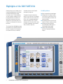
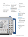
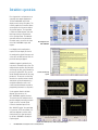
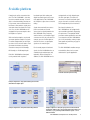
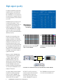
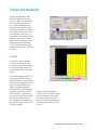
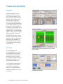
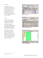
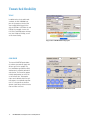
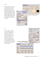
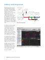
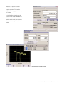
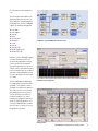
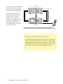
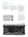
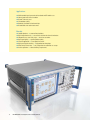
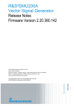
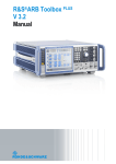
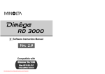
Version 01.00 ¸AMU200A Baseband Signal Generator and Fading Simulator Versatile realtime I/Q source and cost-effective baseband fading simulator in a single unit ◆ Scalable platform ◆ Single-path or dual-path instrument ◆ Arbitrary waveform generator with 16/64/128 Msample ◆ Digital standards including GSM/EDGE, 3GPP FDD, CDMA2000 ®, EUTRA/LTE, TD‑SCDMA, WLAN, WiMAX, DVB-H, GPS, etc ◆ Dual-channel fading simulator supporting predefined fading scenarios ◆ Versatile signal inputs and outputs ◆ 3-year calibration cycle June 2007 Highlights of the ¸AMU200A Growing cost pressure is leading to ever increasing modularization in the design of modern communications equipment and systems. To launch products as early as possible, complex tests are being performed at the module level long before integration into the overall product or system takes place. This increases test requirements at the baseband level. aveform generator, and a channel w simulator in a single unit. The optional two-path functionality makes it easy to generate even complex signal scenarios. You can simulate interference, noise, multipath propagation, and antenna diversity. Plus, you can determine their effect on a device under test (DUT) reproducibly, with minimum effort, and with a single unit. The universal ¸AMU200A baseband generator has been specially devised for this task. It combines the functionality of a realtime I/Q source, an arbitrary ¸AMU200A Baseband Signal Generator and Fading Simulator Scalable platform ◆ Up to two complete baseband paths ◆ Configuration as a fading simulator, an I/Q source, or an all-in-one instrument offering fading simulation and signal generation ◆ Baseband generators with universal coders for realtime signal generation ◆ Arbitrary waveform generators with 16 Msample, 64 Msample, or 128 Msample memory depth ◆ Analog single-ended, analog differential, and digital baseband outputs ◆ Up to two baseband inputs (analog or digital) ◆ Lossless combination of up to four baseband signals in the digital domain (e.g. for testing multistandard base stations) High signal quality ◆ 40 MHz I/Q bandwidth with flat frequency response of typ. 0.03 dB ◆ Excellent ACLR performance of typ. +78 dB with 3GPP FDD (test model 1, 64 DPCH) ◆ Wideband noise of typ. –155 dBc ◆ Low inherent EVM Unmatched flexibility ◆ Support of a large number of digital standards, including GSM/EDGE, 3GPP FDD, HSPA, CDMA2000®, TD‑SCDMA, WLAN, WiMAX, DVB-H, GPS, EUTRA/LTE ◆ Four code channels in realtime for 3GPP FDD ◆ Change of modulation from slot to slot for GSM/EDGE ◆ Multisegment waveform mode for fast signal switching ◆ Arbitrary waveform generator supported by ¸WinIQSIM2TM simulation software ◆ Pulse generation with pulse sequencer option from Rohde & Schwarz ◆ Direct waveform transmission via MATLAB® ◆ Internal 40 Gbyte hard disk as standard for storing waveforms and modulation data Fading and interference simulation ◆ Dual-channel realtime fading simulator ◆ Up to 20 taps per channel ◆ Time resolution down to 0.01 ns ◆ Profiles for static and dynamic fading scenarios ◆ Additional noise simulation ◆ Ideal for diversity tests Intuitive operation ◆ Color display with 800 × 600 pixels (SVGA format) ◆ Intuitive user interface with graphical display of signal flow (block diagram) ◆ Graphical display of baseband signals through built-in transient recorder ◆ Context-sensitive help system Connectivity ◆ Remote control via GPIB and LAN ◆ USB connectors for keyboard, mouse, and memory stick ◆ VGA connector ◆ User-selectable trigger and marker signals ¸AMU200A Baseband Signal Generator and Fading Simulator Intuitive operation Ease of operation is an important asset especially with complex applications. The ¸AMU200A's large SVGA display reveals settings at a glance. The intuitive graphical user interface allows you to operate the instrument without any special expertise. The signal flow is shown in a block diagram, with each block representing a functional unit of the signal generator. The block diagram also shows the interconnection of various sources as well as the status of the ¸AMU200A's inputs and outputs. Block diagram of the ¸AMU200A Level display can be configured as required. You can display the level of the analog or the digital I/Q output, and select either the RMS value or have the peak value directly displayed. Additional support is provided by the instrument's innovative help system. The tooltip function specifies the permissible value range for each setting window. By pressing the yellow HELP key, you will obtain detailed information on all setting parameters. The context-sensitive help describes the specific function in detail, and includes general information (e.g. on digital standards) as well as the remote-control commands required for programming automatic test sequences. Context-sensitive help system Via the graphics block in the block diagram, you can access the ¸AMU200A's graphics functions. The built-in transient recorder makes it possible to display internally generated signals as well as external signals fed via the baseband inputs of the ¸AMU‑B17 option. You can display I/Q, spectrum, CCDF, constellation, eye and vector diagrams, and thus easily check whether the signal generated by the ¸AMU200A is actually the required signal. Graphics block with I/Q, vector, CCDF, and spectrum diagram ¸AMU200A Baseband Signal Generator and Fading Simulator Scalable platform Complex tasks call for customized solutions. The ¸AMU200A is, therefore, based on a modular concept. It is available as a baseband fading simulator, an I/Q generator, and a multifunction baseband source that combines signal generation and channel simulation in a single unit. Plus, the ¸AMU200A can be equipped with up to two complete baseband paths as required. With two baseband paths, two internal generators produce complex I/Q signals in realtime independently of each other by means of their universal coders. Each generator also includes an arbitrary waveform memory with 16 Msample, 64 Msample, or 128 Msample depth. Each ¸AMU200A baseband path can be provided with a separate b aseband input. Both analog and digital baseband signals can be externally applied to the ¸AMU200A, for example to subject them to internal fading. equipped with an 18-bit digital output for each signal path. This makes the instrument a versatile baseband signal source that can be used with a variety of DUTs independently of their interfaces. Signals from maximally four sources (two internal and two external sources) can be digitally added in the ¸AMU200A. Using frequency and level offsets, even complex signal scenarios can easily be generated. For example, you can simulate adjacent channel interferers, or superimpose signals on the wanted signal. For channel simulation, the ¸AMU200A can be equipped with up to two fading simulators, depending on requirements. Two optional AWGN generators and an optional bit error ratio tester round out the ¸AMU200A to give it full functionality, making it a platform capable of performing any type of baseband tests. For the analog output of baseband signals, the ¸AMU200A offers as standard single-ended outputs and, optionally, differential outputs. In addition, the ¸AMU200A can be The ¸AMU200A's modular concept and scalability allow it to be customtailored to the specific application. Automatic baseband input level setting Example configuration 1: single-path baseband generator with a differential and a digital output Example configuration 2: dual-path baseband fading simulator Example configuration 3: dual-path signal generator and baseband fading simulator: addition of up to four baseband signals with frequency and level offsets, e.g. for generating realtime multicarrier signals – even to different standards ¸AMU200A Baseband Signal Generator and Fading Simulator High signal quality Developing and producing high-quality components places great demands on the test equipment. In the case of the ¸AMU200A, the error introduced by the signal source is negligible relative to the measured quantity to be determined on the DUT. Broadband signals are frequently used in mobile communications. To minimize distortion during transmission, the components involved should have a frequency response as flat as possible. The ¸AMU200A features a typical frequency response as low as 0.03 dB across its entire baseband bandwidth of 40 MHz (for I and Q). EVM measurement of a WiMAX OFDMA signal generated with the ¸AMU200A –20 k2 k3 Moreover, the ¸AMU200A offers very low wideband noise of typically –155 dBc. Harmonics suppression of typically >60 dB and low inter modulation products yield a wide dynamic range in which signals can be generated interference-free. This makes the ¸AMU200A suitable for the hardware simulation of baseband chips as well as for intermodulation tests on complete RF frontends. An excellent adjacent-channel leakage ratio (ACLR) is another outstanding feature of the ¸AMU200A. The instrument offers an ACLR of typically 78 dB for 3GPP FDD (test model 1, –30 0.2 k in dB Normally, linear and nonlinear interference effects (carrier leakage, I/Q imbalance, quadrature error, AM/AM, AM/PM conversion) occur inside an I/Q modulator. This leads to errors in the constellation diagram and thus to an increased error vector magnitude (EVM). Its outstanding signal quality makes the ¸AMU200A an ideal choice for I/Q modulator tests. With WiMAX OFDMA, for example, the instrument exhibits a typical EVM of 54 dB. A in dB 0.25 0.15 –40 0.10 –50 0.05 0 –60 –0.05 –70 –0.10 –0.15 –80 –0.20 –90 –0.25 0 0.5 1 1,5 2 2.5 3 3.5 –100 4 104 f in Hz (×10 7 ) Typical frequency response of the analog I/Q outputs of the ¸AMU200A 105 106 107 f in Hz Low harmonics of the analog I/Q outputs of the ¸AMU200A I I Q I/Q modulator RF Q LO I/Q modulator test via differential baseband outputs (¸AMU-B16) of the ¸AMU200A 64 DPCH). The ACLR is so low that it cannot be captured with conventional baseband analyzers because their inherent noise covers up the ACLR of the ¸AMU200A. This makes the ¸AMU200A Baseband Signal Generator and Fading Simulator ¸AMU200A an ideal signal source even for the most demanding tests. Unmatched flexibility The merging of digital mobile radio, multimedia applications, and navigation services places exacting demands on the functionality of signal generators. The ¸AMU200A baseband signal generator and fading simulator fully meets these demands. Its modular design makes it a highly versatile instrument. Applications range from use in the development of individual baseband components and tests of base station modules through to applications in the production of complex mobile radio systems. The ¸AMU200A supplies standard-conforming signals at the press of a button. Channel table with eight active HSDPA channels 3GPP FDD For 3GPP FDD, the ¸AMU200A simultaneously simulates up to four base stations with 128 code channels or up to four mobile radio stations. Up to four code channels can be generated in realtime. The instrument supports functions such as transmit power control (TPC) and compressed mode as well as orthogonal channel noise simulation (OCNS). It also generates high-speed packet access signals in the uplink and downlink (HSUPA/HSDPA). The ¸AMU200A functionality further covers the 3GPP FDD test models, the uplink reference measurement channels, and the HSUPA fixed reference channels (FRC). The ¸AMU200A is thus capable of simulating realistic signal scenarios as occur in 3GPP FDD networks. Code domain display with eight active HSDPA channels Moreover, the ¸AMU200A can selectively generate bit errors and block errors in the coded signal. This allows the internal bit error ratio (BER) and block error ratio (BLER) calculations of a base station to be checked in line with TS 25.141. ¸AMU200A Baseband Signal Generator and Fading Simulator Unmatched flexibility EUTRA/LTE EUTRA (evolved UMTS terrestrial radio access), which is also referred to as LTE (long term evolution), is the advancement of the UMTS standard to implement a packet-optimized system with higher data rates and lower latencies. The ¸AMU200A allows the easy generation of baseband signals of up to 20 MHz bandwidth in line with Release 8 of the 3GPP specification. In the downlink, up to 20 subframes can be separately configured. which are then periodically output. The ¸AMU200A supports the configuration of data blocks and control channels, as well as the global definition of P-SCH, S-SCH, and the reference signal structure. Resource allocation is shown in a straightforward, graphical time plan. Additionally, the ¸AMU200A functionality is going to be expanded to also include uplink signal generation. TD-SCDMA LTE downlink frame configuration Graphical time plan: multiple LTE downlink frames with user-defined resource allocation The ¸AMU200A with the ¸AMU-K50 option generates up to four TD-SCDMA cells with a variable switching point between uplink and downlink transmission. This makes it easy to generate standard-conforming signals at the physical layer, e.g. for multicarrier power amplifier tests. The ¸AMU-K51 option allows realtime generation of the PCCPCH and several DPCHs. The option further provides fully channel-coded signals, enabling even complex receiver tests to be performed. ¸AMU200A Baseband Signal Generator and Fading Simulator TD-SCDMA frame configuration CDMA2000® In addition to 3GPP FDD, the ¸AMU200A supports CDMA2000 ® in the 1X mode with full channel coding. It also covers cdmaOne as a subset. Like 3GPP FDD, which includes HSDPA as a special high-data-rate mode, CDMA2000 ® includes 1xEV‑DV, also known as radio configuration 10 (RC 10). The 1xEV-DV standard is also supported by the ¸AMU200A. CDMA2000 ® channel table WiMAX The IEEE 802.16 WiMAX standard is becoming more and more important for radiocommunications applications involving higher data rates. The ¸AMU200A supports signal generation in line with IEEE 802.16-2004 and IEEE 802.16-2005 including channel coding. OFDM, OFDMA, fixed WiMAX, mobile WiMAX, and WiBRO are covered. Configuration of WiMAX OFDMA signals OFDMA functionality includes the FFT sizes, bandwidths, and modulation types of the standard, as well as multiple zones (e.g. PUSC, FUSC, AMC, sounding), segments, ranging, fast feedback, HARQ, and many other functions. The signal can easily be configured directly on the instrument by means of the graphical time plan display. Time plan of a WiMAX OFDMA signal CDMA2000® is a registered trademark of the Telecommunications Industry Association (TIA – USA). ¸AMU200A Baseband Signal Generator and Fading Simulator Unmatched flexibility WLAN In addition to the classic mobile radio standards, the ¸AMU200A supports the generation of wireless local area network (WLAN) signals in line with the IEEE 802.11a, IEEE 802.11b, and IEEE 802.11g standards. It covers the CCK, PBCC, and OFDM modes with data rates from 1 Mbps to 54 Mbps, as well as full channel coding. Easy generation of WLAN IEEE 802.11a/b/g signals GSM/EDGE The internal GSM/EDGE option allows the realtime generation of signals with all burst types of the standard. The level, modulation type (GMSK or 8PSK), and data can be separately defined for each timeslot. The instrument supports multislot configurations as well as the use of half-rate slots. Two complete frames can be defined, which are cyclically output at user-definable repetition rates. It is thus possible to simulate a dynamic signal change within a timeslot from one frame to the next. Configuration of two GSM/EDGE frames with different content 10 ¸AMU200A Baseband Signal Generator and Fading Simulator DVB-H More and more products offer not only voice communication, but also multi media functionality such as DVB-H. To be able to test such products, the ¸AMU200A provides the required DVB-H signals in addition to the mobile radio signals. For DVB-H, the instrument supports the 5 MHz, 6 MHz, 7 MHz, and 8 MHz bandwidths as well as the QPSK, 16QAM, and 64QAM modulation modes. It offers 2K, 4K, and 8K transmission as well as functions such as time slicing and MPE-FEC. Configuration of a DVB-H baseband signal GPS The internal digital GPS standard enables the simulation of up to four satellites of the global positioning system (GPS) in a single baseband. Realistic function tests can be performed based on almanac data updated at weekly intervals. C/A codes as well as P codes are supported. Moreover, positions can be specified in geographical coordinates in the Localization mode. This makes it possible to test the receiver's localization performance at baseband level like under real conditions. Simulation of up to four GPS satellites by each universal coder of the ¸AMU200A ¸AMU200A Baseband Signal Generator and Fading Simulator 11 Arbitrary waveform generator The arbitrary waveform generators of the ¸AMU200A with 16 Msample, 64 Msample, or 128 Msample memory depth allow the use of any precalculated waveforms. Waveforms can be calculated using the ¸WinIQSIM2TM simulation software or any other suitable calculation software (e.g. MATLAB®). Waveform import into the ¸AMU200A is very easy, which makes the instrument an ideal choice for generating proprietary signals. On the other hand, it can be used for simulating signals in line with new digital standards when standardization is still at an early stage. Waveform 1 Automatic repetition of partial waveform within segment Resulting waveform in output RAM Waveform 2 Segment 1 Segment 2 Segment 3 Output signal Waveform 3 Segment switching by means of ¸AMU200A user interface or IEC/IEEE bus Multisegment waveform generation Test systems, in particular in production, often switch between different test signals at high speed. In the multisegment waveform mode, different waveforms can be combined to form a sequence. Switchover between individual segments is effected in typically 7 µs. In the seamless mode, a multi segment waveform is output without any interruption between the segments. Pulse sequences can be generated by means of the ¸pulse sequencer software. This powerful tool allows you to generate typical radar pulses such as FM chirps, specially modulated bursts, or complete pulse trains in next to no time. Multicarrier signals can be generated from different waveforms by means of an internal editor. Delays as well as frequency and level offsets can easily be defined. This allows signals for MCPA tests, for example, to be configured directly on the instrument. 12 Generation of baseband pulses by means of the ¸pulse sequencer software (¸AMU-K6) ¸AMU200A Baseband Signal Generator and Fading Simulator Moreover, it is possible to cascade multicarrier waveforms and multi segment waveforms. Even complex signals with a varying spectrum can thus be simulated. Its high flexibility and ample range of functions make the ¸AMU200A one of the most versatile baseband sources available on the market – an instrument that covers future requirements even today. Internal multicarrier waveform generation ¸AMU200A Baseband Signal Generator and Fading Simulator 13 Fading and interference simulation The trend toward ever higher data rates leads to increasingly complex mobile radio standards. Analyzing the behavior of products under realistic transmission conditions is, therefore, becoming more and more important. The ¸AMU200A baseband signal generator and fading simulator is a costeffective solution for performing this task. The ¸AMU200A can be equipped with up to two baseband fading simulators. In the single-path mode, up to 40 fading paths are available at a bandwidth of 80 MHz and a resolution of 10 ns. With a smaller bandwidth (50 MHz or 30 MHz) and a lower number of paths (16 or 24 paths), resolution as high as 0.01 ns is achieved. With dual-path fading, up to 20 different propagation paths of a signal can be simulated for each channel. The capability of realtime fading simulation simultaneously in both channels makes the ¸AMU200A ideal for RX and TX diversity tests. It simulates the conditions encountered on receivers with two receiving antennas (RX diversity) just as easily as the reception of several TX signals by one receiving antenna (TX diversity). Rician fading of a squarewave-filtered QPSK signal (change in amplitude and phase) Fading simulator Signal paths 1 1 Fading paths 20 12 RF bandwidth 80 MHz 30 MHz Time resolution 10 ns 10 ps Fading simulator and fading simulator extension 1 8 50 MHz 10 ps Signal paths Fading paths RF bandwidth Time resolution 1 16 50 MHz 10 ps 1 40 80 MHz 10 ns 1 24 30 MHz 10 ps 2 12 30 MHz 10 ps Relationship between number of fading paths, bandwidth, and time resolution Setting of the fading parameters is very convenient. For standard-conforming channel simulations, you only need to select the desired standard from a list. Predefined fading scenarios are available for GSM/EDGE, 3GPP FDD, CDMA2000 ®, WLAN, WiMAX, and DAB, for example. All fading parameters are also accessible via a fading path table that allows even special test requirements to be covered. For example, correlations between the two fading channels can be set, and thus the degree of similarity between Configuration of the ¸AMU200A for TX diversity tests 14 2 20 80 MHz 10 ns ¸AMU200A Baseband Signal Generator and Fading Simulator 2 8 50 MHz 10 ps the two channels defined for diversity tests. The current path configuration can be displayed graphically at any time. The delay, amplitude, and fading profile are displayed directly. The ¸AMU200A supports the following fading profiles: ◆ ◆ ◆ ◆ ◆ ◆ ◆ ◆ ◆ ◆ ◆ Static path Pure Doppler Rayleigh Rician Constant phase Lognormal Suzuki Gaussian Gaussian DAB WiMAX Doppler (SUI) WiMAX Rice (SUI) Configuration of the ¸AMU200A for RX diversity tests Moreover, the ¸AMU200A supports scenarios introduced by 3GPP such as birth-death propagation (testing of receiver performance for disappearance and reappearance of a signal, for example, when a caller walks around the corner of a building while on the phone) and moving-delay propagation (testing of receiver performance for slow changes in delay). The ¸AMU200A can additionally be equipped with two internal AWGN generators. These allow the realistic simulation of statistical noise processes. They enable receiver tests with static path propagation as well as general tests for determining the immunity of baseband modules, e.g. to noise introduced by components connected ahead. The powerful algorithms used in the ¸AMU200A allow a defined noise level to be set across the system bandwidth to be analyzed. Visualization of path configuration Fading path table ¸AMU200A Baseband Signal Generator and Fading Simulator 15 ¸AMU 200 A Due to its scalability, the ¸AMU200A is optimally suited for combination with other instruments. It can be configured as required for the intended application. The ¸AMU200A is a reliable and comprehensive solution for channel simulation. It allows the behavior of products under real operating conditions to be reproducibly analyzed and predicted already at an early stage of development. In production, the ¸AMU200A helps to safeguard the required product quality. Fading and AWGN Ref Q Q I I RF ¸CMU 200 A As a baseband fading simulator, the ¸AMU200A combined with the ¸CMU200A radiocommunication tester allows mobile phone testing with faded RF signals including signaling Advantages of fading simulation in the baseband Conventional fading simulators convert the RF signal to the IF, perform fading, and then reconvert the signal to the RF. It is, however, less costly to simulate fading prior to the first conversion to the carrier frequency, i.e. at the baseband level (I and Q), and then convert the signal to the required RF in the test system. Signals will thus not be impaired by the effects of multiple conversion. 16 ¸AMU200A Baseband Signal Generator and Fading Simulator Connectivity Trigger and marker signals Peripherals Remote control Two marker outputs and one trigger input are available on the front panel of the ¸AMU200A to synchronize the instrument with external equipment. Further marker and trigger connectors are provided on the rear panel . The ¸AMU200A contains four USB host connectors (two on the front panel , two on the rear panel ) for connecting a mouse, keyboard, and a USB mass storage device (e.g. a memory stick, CD-ROM, or hard disk). A VGA connector for an external monitor is also provided. The ¸AMU200A can be remotely controlled via LAN or GPIB . The SCPI commands for controlling the ¸AMU200A baseband functions are compatible with those of the ¸SMU200A, ¸SMJ100A, and ¸SMATE200A. Moreover, the ¸AMU200A can conveniently be controlled via a network using Windows Remote DesktopTM. BER/BLER test connector Trigger input and marker outputs on the front panel of the ¸AMU200A An optional bit and block error ratio tester (¸AMU-K80) is available for the ¸AMU200A. The tester determines the bit or block error ratio by comparing incoming data with pseudorandom bit sequences (PRBS). Mask and restart signals can be used in addition to define the part of the input data to be taken into account in error ratio measurement. Rear view of the ¸AMU200A ¸AMU200A Baseband Signal Generator and Fading Simulator 17 Applications ◆ ◆ ◆ ◆ ◆ ◆ Multistandard signal generation for baseband and RF module tests Channel and interference simulation RX and TX diversity tests I/Q modulator tuning Hardware simulation of baseband chips Bit and block error ratio measurement Benefits ◆ ◆ ◆ ◆ ◆ ◆ ◆ ◆ 18 Scalable platform → custom-tailored solutions High integration density → cost-effective solution for channel simulations Component tests at an early stage → faster time to market High signal quality → superior product quality Versatile application → future-proof investment High-speed signal switching → high production throughput Wide variety of interfaces → easy integration into automatic test setups Intuitive operation → reduced training requirements ¸AMU200A Baseband Signal Generator and Fading Simulator Ordering information Designation Type Order No. Baseband Signal Generator1) including power cable, Quick Start Guide, and CD-ROM (with operating and service manual) ¸AMU200A 1402.4090.02 Baseband Generator with ARB (128 Msample) and Digital Modulation (realtime) ¸AMU-B9 1402.8809.02 Baseband Generator with ARB (64 Msample) and Digital Modulation (realtime) ¸AMU-B10 1402.5300.02 Baseband Generator with ARB (16 Msample) and Digital Modulation (realtime) ¸AMU-B11 1402.5400.02 Baseband Main Module ¸AMU-B13 1402.5500.02 Differential I/Q Output ¸AMU-B16 1402.5800.02 Analog/Digital Baseband Inputs ¸AMU-B17 1402.5900.02 Digital I/Q Output ¸AMU-B18 1402.6006.02 Digital Standard GSM/EDGE ¸AMU-K40 1402.6106.02 Digital Standard 3GPP FDD ¸AMU-K42 1402.6206.02 3GPP Enhanced MS/BS Tests incl. HSDPA ¸AMU-K43 1402.6306.02 Digital Standard GPS ¸AMU-K44 1402.6406.02 Digital Standard HSUPA ¸AMU-K45 1402.8909.02 Digital Standard CDMA2000 ® incl. 1xEV-DV ¸AMU-K46 1402.6502.02 Digital Standard IEEE 802.11 (a/b/g) ¸AMU-K48 1402.6706.02 Digital Standard IEEE 802.16 ¸AMU-K49 1402.7002.02 Digital Standard TD-SCDMA ¸AMU-K50 1402.8950.02 Digital Standard TD-SCDMA Enhanced ¸AMU-K51 1402.9005.02 Digital Standard DVB-H ¸AMU-K52 1402.9557.02 Digital Standard EUTRA/LTE ¸AMU-K55 1402.9405.02 Multicarrier CW Signal Generation ¸AMU-K61 1402.7102.02 Digital Standard GSM/EDGE ¸AMU-K240 1402.7602.02 Digital Standard 3GPP FDD ¸AMU-K242 1402.7702.02 3GPP Enhanced MS/BS Tests incl. HSDPA ¸AMU-K243 1402.7802.02 Digital Standard GPS ¸AMU-K244 1402.7902.02 Digital Standard HSUPA ¸AMU-K245 1402.8009.02 Digital Standard CDMA2000 ® incl. 1xEV-DV ¸AMU-K246 1402.8109.02 Options Baseband Digital modulation systems Digital modulation systems using ¸WinIQSIM2TM 2) Digital Standard IEEE 802.11 (a/b/g) ¸AMU-K248 1402.8209.02 Digital Standard IEEE 802.16 ¸AMU-K249 1402.8309.02 Digital Standard TD-SCDMA ¸AMU-K250 1402.8409.02 Digital Standard TD-SCDMA Enhanced ¸AMU-K251 1402.8509.02 Digital Standard DVB-H ¸AMU-K252 1402.9505.02 Digital Standard EUTRA/LTE ¸AMU-K255 1402.9457.02 Multicarrier CW Signal Generation ¸AMU-K261 1402.8609.02 ¸AMU-K262 1402.8709.02 Additive White Gaussian Noise (AWGN) using ¸WinIQSIM2 TM 2) ¸AMU200A Baseband Signal Generator and Fading Simulator 19 Digital modulation systems using external PC software Digital Standard Bluetooth® ¸AMU-K5 1402.9257.02 Pulse Sequencer ¸AMU-K6 1402.9805.02 Fading Simulator ¸AMU-B14 1402.5600.02 Fading Simulator Extension ¸AMU-B15 1402.5700.02 Additive White Gaussian Noise (AWGN) ¸AMU-K62 1402.7202.02 Dynamic Fading and Enhanced Resolution ¸AMU-K71 1402.7302.02 Enhanced Fading Profiles ¸AMU-K72 1402.9605.02 BER/BLER Measurement ¸AMU-K80 1402.7402.02 I/Q Rear Connectors ¸AMU-B81 1402.6858.02 Fading and noise Other options Recommended extras 1) Hardcopy manuals (in English, UK) 1402.5222.32 Hardcopy manuals (in English, US) 1402.5222.39 19" Rack Adapter ¸ZZA-411 1096.3283.00 Adapter for Telescopic Sliders ¸ZZA-T45 1109.3774.00 BNC Adapter for AUX I/O Connector ¸SMU-Z5 1160.4545.02 Keyboard with USB Interface (US assignment) ¸PSL-Z2 1157.6870.04 Mouse with USB Interface, optical ¸PSL-Z10 1157.7060.03 External USB CD-RW Drive ¸PSP-B6 1134.8201.22 The base unit must be ordered with an ¸AMU-B13 option plus one option out of ¸AMU-B9/-B10/-B11/-B17. ¸WinIQSIM2 TM requires an external PC. 2) ¸AMU200A Baseband Signal Generator and Fading Simulator 20 Specifications in brief Baseband generator General data Waveform memory 16/64/128 Msample Sampling rate 100 MHz Analog single-ended (standard) 0.02 V to 2 V (EMF, 50 W) Baseband bandwidth 40 MHz Analog differential (optional) 0.04 V to 4 V (EMF, 50 W) Digital (optional) LVDS level, 18 bit Supported modulation types ASK 0 % to 100 % FSK MSK, 2FSK, 4FSK, 8FSK, 16FSK PSK BPSK, QPSK, QPSK 45° offset, OQPSK, π/4-QPSK, π/2-DBPSK, π/4-DQPSK, π/8-D8PSK, 8PSK, 8PSK EDGE QAM 16QAM, 32QAM, 64QAM, 256QAM, 1024QAM Supported standards and digital systems (depending on options) GSM/EDGE, 3GPP FDD, CDMA2000 ®, LTE/EUTRA, TD-SCDMA, WLAN, WiMAX, DVB-H, GPS, user-defined multicarrier CW I/Q outputs I/Q inputs Analog single-ended (optional) Vi 2 + Vq2 = 0.5 V (50 W full scale) Digital (optional) Interfaces LVDS level, 18 bit IEEE 488.2 LAN (100BaseT) 4 × USB host 1 × USB slave VGA Fading simulator Fading bandwidth 80/50/30 MHz (RF) Fading profiles Standard constant phase, pure Doppler, Rayleigh, Rician, lognormal With the ¸AMU-K72 option Gaussian, Gaussian DAB, WiMAX Doppler, WiMAX Rice Predefined fading scenarios Standard CDMA2000 ®, GSM, NADC, PCN, TETRA, Hiperlan With the ¸AMU-K71 option 3GPP FDD, moving delay, birth-death With the ¸AMU-K72 option SUI1 to SUI6 ITU OIP-A, ITU OIP-B, ITU V-A, DABRA, DAB-TU, DAB-SFN Signal quality of analog I/Q outputs Frequency response Magnitude up to 10 MHz typ. 0.02 dB Magnitude up to 40 MHz typ. 0.03 dB I/Q balance Magnitude up to 10 MHz typ. 0.01 dB Magnitude up to 40 MHz typ. 0.02 dB Spectral purity SFDR (sinewave) up to 2 MHz >70 dB SFDR (sinewave) up to 20 MHz typ. 60 dB Phase noise for 10 MHz sinewave at 20 kHz offset typ. –150 dBc Wideband noise for 10 MHz sinewave at 1 MHz offset typ. –155 dBc ¸AMU200A Baseband Signal Generator and Fading Simulator 21 Certified Environmental System ISO 9001 ISO 14001 DQS REG. NO 1954 QM DQS REG. NO 1954 UM For specifications, see PD 5213.7954.22 and www.rohde-schwarz.com (search term: AMU200A) www.rohde-schwarz.com Europe: +49 1805 12 4242, [email protected] USA and Canada: +1-888-837-8772, [email protected] Asia: +65 65 130 488, [email protected] ¸ is a registered trademark of Rohde & Schwarz GmbH & Co. KG · Trade names are trademarks of the owners · Printed in Germany (ch) PD 5213.7954.12 · Version 01.00 · June 2007 · ¸AMU200A · Data without tolerance limits is not binding · Subject to change Certified Quality System