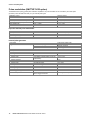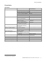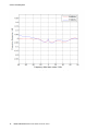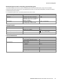
1
SGT100A_dat-sw_en_3607-0217-22_cover.indd 1 Data Sheet | 01.00 Test & Measurement R&S®SGT100A SGMA Vector RF Source Specifications 27.05.2014 11:30:07 Version 01.00, May 2014 CONTENTS Definitions ....................................................................................................................................................................... 3 Key features .................................................................................................................................................................... 4 Specifications .................................................................................................................................................................. 5 RF performance................................................................................................................................................................................. 5 Frequency ...................................................................................................................................................................................... 5 Reference frequency ...................................................................................................................................................................... 5 Level .............................................................................................................................................................................................. 6 Spectral purity ................................................................................................................................................................................ 8 Phase coherence (R&S®SGT-K90 option) ...................................................................................................................................... 9 Simultaneous modulation .................................................................................................................................................................. 9 Pulse modulation (R&S®SGT-K22 option) ........................................................................................................................................ 10 Input for external pulse modulation............................................................................................................................................... 10 Internal pulse generator ............................................................................................................................................................... 10 I/Q modulation ................................................................................................................................................................................. 11 I/Q modulator ............................................................................................................................................................................... 11 Baseband bypass mode for externally generated I/Q signals ....................................................................................................... 13 Analog I/Q inputs.......................................................................................................................................................................... 13 Internal baseband I/Q................................................................................................................................................................... 13 Arbitrary waveform generator (R&S®SGT-K510 option) ................................................................................................................ 14 Multisegment and multicarrier arbitrary waveform mode .................................................................................................................. 15 Modulation performance for GSM/EDGE and 3GPP FDD digital standards .................................................................................. 16 Digital standards with R&S®WinIQSIM2 ........................................................................................................................................ 17 Digital baseband connectivity (R&S®SGT-K18 option).................................................................................................................. 18 Internal additive white Gaussian noise (AWGN, R&S®SGT-K62 option)........................................................................................... 19 Remote control ................................................................................................................................................................................ 19 Connectors ...................................................................................................................................................................................... 20 Rear panel connectors ................................................................................................................................................................. 20 General data.................................................................................................................................................................................... 21 Ordering information .................................................................................................................................................... 22 2 Rohde & Schwarz R&S®SGT100A SGMA Vector RF Source Version 01.00, May 2014 Definitions General Product data applies under the following conditions: • • • • Three hours storage at ambient temperature followed by 30 minutes warm-up operation Specified environmental conditions met Recommended calibration interval adhered to All internal automatic adjustments performed, if applicable Specifications with limits Represent warranted product performance by means of a range of values for the specified parameter. These specifications are marked with limiting symbols such as <, ≤, >, ≥, ±, or descriptions such as maximum, limit of, minimum. Compliance is ensured by testing or is derived from the design. Test limits are narrowed by guard bands to take into account measurement uncertainties, drift and aging, if applicable. Specifications without limits Represent warranted product performance for the specified parameter. These specifications are not specially marked and represent values with no or negligible deviations from the given value (e.g. dimensions or resolution of a setting parameter). Compliance is ensured by design. Typical data (typ.) Characterizes product performance by means of representative information for the given parameter. When marked with <, > or as a range, it represents the performance met by approximately 80 % of the instruments at production time. Otherwise, it represents the mean value. Nominal values (nom.) Characterize product performance by means of a representative value for the given parameter (e.g. nominal impedance). In contrast to typical data, a statistical evaluation does not take place and the parameter is not tested during production. Measured values (meas.) Characterize expected product performance by means of measurement results gained from individual samples. Uncertainties Represent limits of measurement uncertainty for a given measurand. Uncertainty is defined with a coverage factor of 2 and has been calculated in line with the rules of the Guide to the Expression of Uncertainty in Measurement (GUM), taking into account environmental conditions, aging, wear and tear. Device settings and GUI parameters are indicated as follows: “parameter: value”. Typical data as well as nominal and measured values are not warranted by Rohde & Schwarz. Rohde & Schwarz R&S®SGT100A SGMA Vector RF Source 3 Version 01.00, May 2014 Key features Dedicated ATE digital source • • • • • • • I/Q-modulated RF source in the frequency range from 80 MHz to 3 GHz or 6 GHz Very fast frequency and level setting times via PCIe interface Maximum level of +22 dBm (typ.). Wear-free electronic attenuator Integrated ARB with up to 1 Gsample memory depth and 160 MHz RF bandwidth External software (R&S®SGMA GUI) for remote control of multiple instruments Field-upgradeable Space-saving operation due to small dimensions • • Smallest signal generator in its class: 1 height unit, ½ × 19" Lightweight High performance at an attractive price • • • • • • • Low SSB phase noise of typ. –133 dBc (measured, 20 kHz carrier offset, f = 1 GHz, 1 Hz measurement bandwidth) Wideband noise of < –145 dBc Nonharmonics of < –76 dBc (> 10 kHz carrier offset, f ≤ 1500 MHz) Very high level accuracy and repeatability Optional pulse modulation capability and internal pulse generator Optional high-stability reference oscillator Optional coherent LO input/output Minimized total cost of ownership • • • 4 Attractive initial cost Long calibration interval of 3 years Simplified error diagnostics through built-in selftests Rohde & Schwarz R&S®SGT100A SGMA Vector RF Source Version 01.00, May 2014 Specifications RF performance Frequency Frequency range Resolution of setting Resolution of synthesis Setting time Resolution of phase offset setting CW I/Q with option R&S®SGT-KB106 CW I/Q 1 MHz to 3 GHz 80 MHz to 3 GHz 1 MHz to 6 GHz 80 MHz to 6 GHz 0.001 Hz 0.174 µHz (nom.) f = 1 GHz to within < 2 × 10⁻⁷ for f > 500 MHz or < 100 Hz for f ≤ 500 MHz with PCIe remote control < 500 μs 0.1° Reference frequency Frequency error Aging (after 30 days of uninterrupted operation) Temperature effect (0 °C to +50 °C) Warm-up time Reference frequency output Connector type Output frequency Output level Source impedance Reference frequency input Connector type Input frequency Frequency locking range Input level range Input impedance at time of calibration in production with the R&S®SGT-B1 option with the R&S®SGT-B1 option with the R&S®SGT-B1 option to nominal thermostat temperature (with R&S®SGT-B1 option only) < 1 × 10⁻⁷ < 1 × 10⁻⁸ < 1 × 10⁻⁶/year < 1 × 10⁻⁹/day, < 1 × 10⁻⁷/year < 2 × 10⁻⁶ < 1 × 10⁻⁷ ≤ 10 min REF/LO OUT on rear panel sine wave instrument set to internal reference instrument set to external reference SMA female REF/LO IN on rear panel SMA female 10 MHz, 100 MHz, 1000 MHz ±10 × 10–6 0 dBm to +16 dBm 50 Ω (nom.) 10 MHz, 1000 MHz applied external reference input frequency or 1000 MHz +6 dBm to +12 dBm, 9 dBm (typ.) 50 Ω (nom.) Rohde & Schwarz R&S®SGT100A SGMA Vector RF Source 5 Version 01.00, May 2014 Level Setting characteristic AUTO: The step attenuator is switched over automatically. The output level is specified over the full range from –120 dBm to +15 dBm. Setting characteristic UNINTERRUPTED LEVEL SETTING: The level is set without changing the step attenuator. The step attenuator is fixed to the current setting. Level changes are performed without interruption. The maximum interruption-free setting range is limited. If this range is exceeded, the spectral purity of the output signal decreases. Setting range Specified level range Resolution of setting Level error Additional level error for pulse modulation Output impedance VSWR in 50 Ω system Setting time Interruption-free level setting range Reverse power from 50 Ω Maximum permissible DC voltage –120 dBm to +25 dBm –120 dBm to +15 dBm (PEP) 0.01 dB Setting Characteristic: AUTO, temperature range from +18 °C to +33 °C 1 MHz ≤ f ≤ 3 GHz < 0.5 dB 3 GHz < f ≤ 6 GHz < 0.9 dB pulse width ≥ 100 ns < 0.3 dB (meas.) in full frequency range, < 1.8 Setting Characteristic: AUTO to < 0.1 dB deviation from final value, < 500 μs Setting Characteristic: AUTO, with PCIe remote control Setting Characteristic: UNINTERRUPTED 0 dB to +20 dB LEVEL SETTING maximum permissible RF power in output 0.5 W at RF power connector 35 V 1 6000 5000 Occurrence 4000 3000 2000 1000 0 0 50 100 150 200 250 300 Setting time / µs 350 400 450 Histogram of level setting times measured via PCIe interface, I/Q modulation from internal baseband. Setting Characteristic AUTO. 1 6 PEP = peak envelope power. Rohde & Schwarz R&S®SGT100A SGMA Vector RF Source 500 Version 01.00, May 2014 28 27 26 Level / dBm 25 24 23 22 21 20 0.001 1 2 3 Carrier frequency / GHz 4 5 6 Maximum available level in CW mode, Setting Characteristic: AUTO (meas.). 0.5 0.4 0.3 Level Accuracy / dB 0.2 0.1 0 -0.1 -0.2 -0.3 -0.4 -0.5 -50 -45 -40 -35 -30 -25 -20 -15 Channel Power / dBm -10 -5 0 5 Level linearity for internally generated LTE uplink signal at various test frequencies (meas.). Rohde & Schwarz R&S®SGT100A SGMA Vector RF Source 7 Version 01.00, May 2014 Spectral purity Harmonics Nonharmonics Subharmonics Wideband noise SSB phase noise level ≤ 8 dBm, CW, I/Q wideband off < –30 dBc level > –10 dBm, offset > 10 kHz from carrier f ≤ 1500 MHz < –76 dBc 1500 MHz < f ≤ 3000 MHz < –70 dBc 3000 MHz < f ≤ 6000 MHz < –64 dBc level > –10 dBm f ≤ 3000 MHz < –76 dBc 3000 MHz < f ≤ 6000 MHz < –68 dBc 1 MHz ≤ f ≤ 6 GHz, < –145 dBc carrier offset 10 MHz, level > 5 dBm, Setting Characteristic: AUTO, 1 Hz measurement bandwidth, CW 80 MHz ≤ f ≤ 6 GHz, < –135 dBc carrier offset 10 MHz, level > 5 dBm, Setting Characteristic: AUTO, 1 Hz measurement bandwidth, I/Q 20 kHz carrier offset, 1 Hz measurement bandwidth f = 1 GHz < –126 dBc, –133 dBc (meas.) f = 2 GHz < –120 dBc, –127 dBc (meas.) f = 6 GHz < –110 dBc, –117 dBc (meas.) SSB phase noise with the R&S®SGT-B1 internal OCXO option (meas.). 8 Rohde & Schwarz R&S®SGT100A SGMA Vector RF Source Version 01.00, May 2014 ® Phase coherence (R&S SGT-K90 option) The R&S®SGT-K90 option provides phase-coherent RF outputs for two or more instruments. LO coupling modes REF/LO OUT states Phase drift over temperature This mode corresponds to internal LO operation. The REF/LO OUT connector can provide the internal LO oscillator signal to enable phasecoherent coupling on other instruments. This mode corresponds to external LO operation at the REF/LO IN connector. The REF/LO OUT connector can provide the external LO oscillator signal to enable phase-coherent coupling on additional instruments. The active local oscillator signal can be routed to the REF/LO OUT connector (in order to couple two or more instruments). drift of RF signal phase difference between two LO coupled instruments R&S®SGT100A when changing ambient temperature by +1 °C, f = 6 GHz, level = +10 dBm Input of phase coherence signal Connector type REF/LO IN on rear panel Input impedance Input level range of external local oscillator signal Frequency range of external local oscillator signal Output of phase coherence signal Connector type REF/LO OUT on rear panel Output impedance Output level range of internal local oscillator signal Frequency range of internal local oscillator signal internal external REF/LO/OFF 0.4° (meas.) SMA female 50 Ω (nom.) 7 dBm to 13 dBm 80 MHz to 6 GHz SMA female 50 Ω (nom.) 7 dBm to 13 dBm 80 MHz to 6 GHz Simultaneous modulation Pulse modulation I/Q modulation Pulse modulation ● I/Q modulation ● ● = compatible Rohde & Schwarz R&S®SGT100A SGMA Vector RF Source 9 Version 01.00, May 2014 Pulse modulation (R&S®SGT-K22 option) The R&S®SGT-K22 option provides pulse modulation capabilities. The pulse modulator can be controlled by an internal pulse generator (comes with R&S®SGT-K22) or by an external pulse signal. Modulation source On/off ratio Rise/fall time External pulse modulation delay Pulse repetition frequency Video feedthrough Pulse overshoot 10 % to 90 % of RF amplitude level < 10 dBm f ≥ 500 MHz external, internal > 80 dB < 20 ns 45 ns (meas.) 0 Hz to 10 MHz < 10 % of RF < 10 % Input for external pulse modulation Connector type Input impedance Threshold voltage Input damage voltage Input polarity USER2 on rear panel selectable selectable SMA female 10 kΩ or 50 Ω (nom.) 1 V (nom.) ±5 V normal, inverse Internal pulse generator Pulse mode Trigger mode Active trigger edge Pulse period Setting range Setting resolution Pulse width Setting range Setting resolution Pulse delay Setting range Setting resolution Double pulse delay Setting range Setting resolution External trigger delay jitter Pulse/video output 10 free run, internally triggered single pulse, double pulse auto externally triggered externally gated positive or negative 100 ns to 100 s 10 ns Pulse widths of double pulses can be set independently. 20 ns to 100 s with external trigger with external trigger 0 s to 100 s 10 ns available on USER2 connector on rear panel in trigger mode auto Rohde & Schwarz R&S®SGT100A SGMA Vector RF Source 10 ns 40 ns to 100 s 10 ns < 20 ns LVTTL signal, 3.3 V (nom.) Version 01.00, May 2014 I/Q modulation I/Q modulator Operating modes RF modulation bandwidth RF frequency response Carrier leakage Suppression of image sideband for entire instrument in modulation bandwidth Error vector 3GPP FDD digital standard, adjacent channel leakage ratio (ACLR) I/Q impairment settings (analog) Offset setting range Offset setting resolution Gain imbalance setting range Gain imbalance setting resolution Quadrature offset setting range Quadrature offset setting resolution 2 external analog I/Q, internal baseband I/Q with external analog I/Q inputs, I/Q wideband off 80 MHz ≤ f ≤ 1 GHz ±5 % of carrier frequency 1 GHz < f ≤ 6 GHz ±50 MHz with external analog I/Q inputs, I/Q wideband on 100 MHz < f ≤ 2.5 GHz ±20 % of carrier frequency 2.5 GHz < f ≤ 6 GHz, I/Q wideband ±500 MHz with internal baseband I/Q, I/Q wideband on 100 MHz < f ≤ 400 MHz ±20 % of carrier frequency f > 400 MHz ±80 MHz with external analog I/Q inputs, I/Q wideband off 80 MHz < f ≤ 1 GHz, < 3 dB (meas.) up to ±5 % of carrier frequency f > 1 GHz, up to ±50 MHz < 3 dB (meas.) with external analog I/Q inputs, I/Q wideband on 100 MHz < f ≤ 2.5 GHz, < 6 dB (meas.) up to ±20 % of carrier frequency 2.5 GHz < f ≤ 6 GHz, up to ±500 MHz < 9 dB (meas.) with internal baseband I/Q, I/Q wideband < 1.0 dB, < 0.3 dB (meas.) on, optimization mode high quality with external analog I/Q inputs, < –45 dBc, < –55 dBc (meas.) without input signal, referenced to full-scale input 2 mode: internal baseband I/Q, > 45 dB, 60 dB (typ.) up to 80 MHz I/Q Bandwidth measured with 16QAM, filter root cosine α = 0.5, 10 kHz symbol rate f > 80 MHz, RMS < (0.4 % + 0.2 % × f/GHz) f > 80 MHz, peak value < (0.8 % + 0.4 % × f/GHz) test model 1, 64 DPCHs, level ≤ 10 dBm PEP, frequency range from 1800 MHz to 2200 MHz 5 MHz offset > 67 dB, 70 dB (meas.) 10 MHz offset > 69 dB, 71 dB (meas.) These impairments are set within the analog I/Q modulator section. They can be used in external wideband I/Q mode and internal baseband I/Q mode. –5 % to +5 % 0.01 % –1.0 dB to +1.0 dB 0.001 dB –8° to +8° 0.01° Value applies after internal readjustment. Rohde & Schwarz R&S®SGT100A SGMA Vector RF Source 11 Version 01.00, May 2014 I/Q modulation frequency response with internal baseband (meas.). 12 Rohde & Schwarz R&S®SGT100A SGMA Vector RF Source Version 01.00, May 2014 Baseband bypass mode for externally generated I/Q signals The baseband bypass mode allows to generate modulated signals below the specified frequency range of the I/Q modulator. Externally generated signals applied to the I or Q baseband input connector can be leveled and amplified by the instrument and are provided at the RF output connector. For the baseband bypass mode, only the data specified in this section is valid. Level setting range Specified level range Frequency response Level error Level linearity 1 MHz ≤ f ≤ 80 MHz, level = 10 dBm attenuator mode AUTO, temperature range from +18 °C to +33 °C, referenced to full-scale input at I or Q connector, 1 MHz ≤ f ≤ 80 MHz attenuator mode FIXED, for setting range of 0 dB to +20 dB –120 dBm to +25 dBm –120 dBm to +15 dBm < 3 dB, < 1 dB (meas.) < 3 dB < 2 dB, < 0.5 dB (meas.) Analog I/Q inputs Connector types Input impedance VSWR Input voltage for full-scale input Input damage voltage I, Q on rear panel up to 100 MHz 100 MHz up to 500 MHz SMA female 50 Ω (nom.) < 1.2 < 1.5 2 2 V i + V q = 0.5 V ±1 V (nom.) Internal baseband I/Q D/A converter Aliasing filter I/Q impairments resolution 16 bit with amplitude, group-delay and Si correction bandwidth (drop to –0.1 dB) 80 MHz (nom.) D/A converter interpolation spectra up to 80 MHz < –80 dBc I offset, Q offset setting range –10 % to +10 % resolution 0.01 % gain imbalance setting range –1 dB to +1 dB resolution 0.001 dB quadrature offset setting range –10° to +10° resolution 0.01° Rohde & Schwarz R&S®SGT100A SGMA Vector RF Source 13 Version 01.00, May 2014 ® Arbitrary waveform generator (R&S SGT-K510 option) Waveform length Nonvolatile memory Sample rate Sample resolution Sample clock source Sample frequency error Bandwidth (RF) using the maximum sample rate Bandwidth (RF) using a reduced sample rate (drop to –0.1 dB) Frequency offset setting range Frequency offset resolution Frequency offset error Triggering Marker outputs 14 1 sample to 32 Msample in one-sample steps with R&S®SGT-K511 option 1 sample to 256 Msample in one-sample steps with R&S®SGT-K511 and R&S®SGT-K512 1 sample to 1 Gsample options in one-sample steps SSD 60 Gbyte 400 Hz to 75 MHz with R&S®SGT-K521 option 400 Hz to 150 MHz with R&S®SGT-K522 option 400 Hz to 200 MHz equivalent to D/A converter 16 bit internal, external internal clock < (5 × 10–14 + reference frequency error) × sample rate (nom.) 60 MHz (nom.) with R&S®SGT-K521 option 120 MHz (nom.) with R&S®SGT-K522 option 160 MHz (nom.) The waveform is automatically interpolated to the internal sample rate of 300 MHz. 0.8 × sample rate (nom.) –30 MHz to 30 MHz with R&S®SGT-K521 option –60 MHz to 60 MHz with R&S®SGT-K522 option –80 MHz to 80 MHz 0.01 Hz < (5 × 10⁻¹⁰ + reference frequency error) × frequency offset (nom.) source internal, external operating modes auto, retrig, armed auto, armed retrig, single, next external trigger delay (in sample) setting range 0 to (216 – 1) resolution 0.01 jitter ±1.67 ns (nom.) external trigger inhibit (in sample) setting range 0 to (226 – 1) resolution 1 external trigger pulse width > 20 ns (nom.) number 2 level LVTTL operating modes unchanged, restart, pulse, pattern, ratio, trigger marker delay (in sample) setting range 0 to (waveform length – 1) setting range without recalculation 0 to 2000 resolution of setting 1 Rohde & Schwarz R&S®SGT100A SGMA Vector RF Source Version 01.00, May 2014 Multisegment and multicarrier arbitrary waveform mode Multisegment waveform number of segments changeover modes extended trigger modes changeover time at 50 MHz clock rate (external trigger, without clock change) seamless changeover Multicarrier waveform sequencer play list length sequencer segment repetitions number of carriers carrier spacing setting range resolution crest factor modes signal period modes single carrier gain setting range resolution single carrier start phase setting range resolution single carrier delay setting range resolution max. 100 segments GUI, remote control, external trigger same segment, next segment, next segment seamless, sequencer 5 µs (meas.) output up to end of current segment, followed by changeover to next segment max. 1024 max. 65535 max. 32 depends on number of carriers and bandwidth (RF) 0.01 Hz maximize, minimize, off longest file, shortest file, user (max. 1 s) –80 dB to 0 dB 0.01 dB 0° to 360° 0.01° 0 s to 1 s 1 ns Operation with R&S®WinIQSIM2™: The software supports download of I/Q data and basic control of the arbitrary waveform generator. Rohde & Schwarz R&S®SGT100A SGMA Vector RF Source 15 Version 01.00, May 2014 Modulation performance for GSM/EDGE and 3GPP FDD digital standards GSM/EDGE Burst on/off ratio Phase error Error vector magnitude Power density spectrum 3GPP FDD Error vector magnitude Adjacent channel leakage ratio (ACLR) with R&S®SGT-K240 option level ≤ 13 dBm PEP, frequency range from 400 MHz to 2000 MHz 100 dB (meas.) MSK, Gaussian filter B × T = 0.3 RMS < 0.4°, 0.15° (typ.) peak 0.4° (meas.) 8PSK EDGE, Gaussian linearized filter, < 0.5 %, 0.25 % (typ.) RMS values measured with 30 kHz resolution bandwidth, referenced to level in band center without power ramping 200 kHz offset < –34 dB, –38 dB (typ.) 400 kHz offset < –66 dB, –70 dB (typ.) 600 kHz offset < –74 dB, –78 dB (typ.) with R&S®SGT-K242 option level ≤ 0 dBm RMS, frequency range from 1800 MHz to 2200 MHz 1 DPCH, RMS < 0.8 %, 0.4 % (typ.) test model 1, 64 DPCHs offset 5 MHz > 68 dB, 71 dB (typ.) offset 10 MHz > 70 dB, 73 dB (typ.) Digital standard 3GPP FDD test model 1, 64 DPCHs ACLR (meas.). 16 Rohde & Schwarz R&S®SGT100A SGMA Vector RF Source Version 01.00, May 2014 Digital standards with R&S®WinIQSIM2 R&S®WinIQSIM2 requires an external PC. The options are described in the R&S®WinIQSIM2 data sheet (PD 5213.7460.22). Cellular standards EUTRA/LTE (R&S®SGT-K255 option) EUTRA/LTE Release 9 and enhanced features (R&S®SGT-K284 option, R&S®SGT-K255 required) EUTRA/LTE Release 10/LTE-Advanced (R&S®SGT-K285 option, R&S®SGT-K255 required) 3GPP FDD (R&S®SGT-K242 option) 3GPP FDD/HSPA/HSPA+, enhanced BS/MS tests (R&S®SGT-K283 option, R&S®SGT-K242 required) GSM/EDGE (R&S®SGT-K240 option) EDGE EVOLUTION (R&S®SGT-K241 option, R&S®SGT-K240 required) CDMA2000® (R&S®SGT-K246 option) 1xEV-DO (R&S®SGT-K247 option) 1xEV-DO Rev. B (R&S®SGT-K287 option, R&S®SGT-K247 required) TD-SCDMA (3GPP TDD LCR) (R&S®SGT-K250 option) TD-SCDMA (3GPP TDD LCR) enhanced BS/MS test including HSDPA (R&S®SGT-K251 option, R&S®SGT-K250 required) TETRA Release 2 (R&S®SGT-K268 option) Wireless connectivity standards IEEE 802.11 a/b/g/n (R&S®SGT-K254 option) IEEE 802.11 ac (R&S®SGT-K286 option, R&S®SGT-K254 required) IEEE 802.16 (R&S®SGT-K249 option) Bluetooth® EDR/low energy (R&S®SGT-K260 option) NFC A/B/C (R&S®SGT-K289 option) Navigation standards GPS 1 satellite (R&S®SGT-K244 option) Galileo 1 satellite (R&S®SGT-K266 option) Glonass 1 satellite (R&S®SGT-K294 option) BeiDou 1 satellite (R&S®SGT-K407 option) Broadcast standards DVB-H/DVB-T (R&S®SGT-K252 option) DAB/T-DMB (R&S®SGT-K253 option) Other standards and modulation systems Multicarrier CW signal generation (R&S®SGT-K261 option) Additional white Gaussian noise (AWGN) (R&S®SGT-K262 option) Rohde & Schwarz R&S®SGT100A SGMA Vector RF Source 17 Version 01.00, May 2014 ® Digital baseband connectivity (R&S SGT-K18 option) External digital I/Q signals can be fed in to the baseband section. The digital I/Q connectivity can be used for the lossless connection of the R&S®SGT100A to the digital I/Q output of other Rohde & Schwarz instruments (e.g. R&S®SMW200A vector signal generator). One R&S®SGT-K18 can be installed. Input parameters Input level Frequency offset I/Q swap Interface I/Q sample rate I/Q data Control signals 18 peak level setting range –60 dB to +3 dB referenced to full scale resolution 0.01 dB crest factor setting range 0 dB to +30 dB resolution 0.01 dB The adjust level function automatically determines the peak level and crest factor of the input signal. With the aid of the frequency offset, the center frequency of the input signal can be shifted in the baseband. The restrictions caused by the modulation bandwidth apply. setting range −80 MHz to +80 MHz resolution 0.01 Hz frequency accuracy < 5 × 10 − 10 × frequency offset + reference frequency error I and Q signals swapped on/off standard in line with Rohde & Schwarz standard for digital I/Q interface level LVDS connector 26-pin MDR data rate up to 200 MHz With source ‘user-defined’, the sample rate must be entered via the parameter ‘sample rate’, no I/Q data clock being necessary. With source ‘digital I/Q in’, the sample rate will be estimated on the basis of the applied I/Q data clock. source user-defined, digital I/Q in sample rate 400 Hz to 200 MHz, max. sample rate depending on interface data rate resolution (user-defined) 0.001 Hz frequency uncertainty (user-defined) < 5 × 10⁻¹⁴ resolution 18 bit logic format two’s complement bandwidth 0.33 × sample rate markers 4 data valid valid samples marked in data stream Rohde & Schwarz R&S®SGT100A SGMA Vector RF Source Version 01.00, May 2014 Internal additive white Gaussian noise (AWGN, R&S®SGT-K62 option) Addition of an AWGN signal of settable bandwidth and settable C/N ratio or Eb/N0 to a wanted signal. Noise C/N, Eb/N0 System bandwidth distribution density crest factor periodicity setting range resolution uncertainty for system bandwidth = symbol rate –24 dB < C/N < 30 dB and crest factor < 12 dB bandwidth for determining noise power setting range standard with R&S®SGT-K521 option with R&S®SGT-K522 option setting resolution Gaussian, statistical, separate for I and Q > 15 dB > (2800 – 1 )/300 MHz –30 dB to +30 dB 0.1 dB < 0.1 dB 1 kHz to 60 MHz 1 kHz to 120 MHz 1 kHz to 160 MHz 100 Hz Remote control Systems Command set remote control via Ethernet, USB remote control via PCIe PCIe (single lane) Ethernet (TCP/IP) 10/100/1000BaseT USB 2.0 SCPI 1999.5 or compatible command sets Rohde & Schwarz instrument driver Rohde & Schwarz R&S®SGT100A SGMA Vector RF Source 19 Version 01.00, May 2014 Connectors Rear panel connectors RF 50 Ω REF/LO IN REF/LO OUT I, Q DIG IQ IN USER1 USER2 USB IN LAN PCI Express 20 RF output reference frequency input or external LO signal input reference frequency output or internal LO signal output input connector for I and Q baseband signals input for I/Q vector-modulated IF signals up to 80 MHz digital input connectivity in line with R&S®Digital I/Q Interface multipurpose input/output pulse and multipurpose input/output remote control of instrument remote control of instrument remote control of instrument Rohde & Schwarz R&S®SGT100A SGMA Vector RF Source SMA female SMA female SMA female SMA female 26-pin MDR SMA female SMA female USB (micro USB) RJ-45 single lane, according to PCI Express external cabling specification Version 01.00, May 2014 General data Power supply AC input voltage range AC supply frequency Max. input current Power consumption Power factor correction Electrical safety Compliance 100 V to 240 V ± 10 % 50 Hz to 60 Hz, –5 %/+5 % 1.7 A 65 W (meas.) in line with EN 61000-3-2 in line with IEC 61010-1, EN 61010-1, CAN/CSA-C22.2 No. 61010-1-04, UL 61010-1 VDE-GS, CCSAUS Test mark EMC Electromagnetic compatibility Mechanical resistance Vibration in line with EN 55011 class A, EN 61326-1 (industrial environment), EN 61326-2-1 sinusoidal 5 Hz to 150 Hz, max. 2 g at 55 Hz, const. 0.5 g at 55 Hz to 150 Hz, in line with EN 60068-2-6 10 Hz to 300 Hz, acceleration 1.2 g (RMS), in line with EN 60068-2-64 in line with MIL-STD-810E, method no. 516.4, procedure I, 40 g shock spectrum random Shock Environmental conditions Temperature range Climatic resistance Altitude Dimensions Weight Calibration interval Recommended calibration interval operating temperature range storage temperature range operating storage W×H×D when fully equipped 0 °C to +50 °C, in line with EN 60068-2-1, EN 60068-2-2 –40 °C to +71 °C +40 °C/95 % rel. humidity, in line with EN 60068-2-30 up to 4600 m up to 4600 m 250 mm × 52.5 mm × 401 mm (9.84 in × 2.07 in × 15.79 in) 1 HU, ½ 19" rack width 4.0 kg (8.82 lb) 40 h/week operation in the full range of the 3 years specified environmental conditions Rohde & Schwarz R&S®SGT100A SGMA Vector RF Source 21 Version 01.00, May 2014 Ordering information Designation Type SGMA Vector RF Source, 1 MHz to 3 GHz RF, baseband hardware included R&S®SGT100A Including power cable, Quick Start Guide and CD-ROM (with operating and service manual) RF options Frequency extension to 6 GHz R&S®SGT-KB106 Reference Oscillator OCXO R&S®SGT-B1 Pulse Modulation R&S®SGT-K22 Phase Coherent Input/Output R&S®SGT-K90 Baseband options Digital baseband connectivity R&S®SGT-K18 ARB baseband generator, 32 MS, 60 MHz RF bandwidth R&S®SGT-K510 ARB memory extension to 256 Msample R&S®SGT-K511 ARB memory extension to 1 GSample R&S®SGT-K512 ARB bandwidth extension to 120 MHz RF Bandwidth R&S®SGT-K521 ARB bandwidth extension to 160 MHz RF Bandwidth R&S®SGT-K522 Noise generation Additive White Gaussian Noise (AWGN) R&S®SGT-K62 ® 3 Digital modulation systems using R&S WinIQSIM2™ GSM/EDGE R&S®SGT-K240 EDGE Evolution R&S®SGT-K241 3GPP FDD R&S®SGT-K242 GPS R&S®SGT-K244 ® CDMA2000 incl. 1x EV-DV R&S®SGT-K246 1xEV-DO Rev. A R&S®SGT-K247 IEEE 802.16 R&S®SGT-K249 TD-SCDMA R&S®SGT-K250 TD-SCDMA Enhanced BS/MS Tests R&S®SGT-K251 DVB-H R&S®SGT-K252 DAB/T-DMB R&S®SGT-K253 IEEE 802.11a/b/g/n R&S®SGT-K254 EUTRA/LTE R&S®SGT-K255 ® Bluetooth EDR R&S®SGT-K260 Multicarrier CW Signal Generation R&S®SGT-K261 Additive White Gaussian Noise (AWGN) R&S®SGT-K262 Galileo R&S®SGT-K266 TETRA Release 2 R&S®SGT-K268 3GPP FDD HSPA/HSPA+ R&S®SGT-K283 EUTRA/LTE Rel.9, enhanced features R&S®SGT-K284 EUTRA/LTE Release 10 (LTE Adanced) R&S®SGT-K285 IEEE 802.11ac R&S®SGT-K286 1xEV-DO Rev. B R&S®SGT-K287 NFC A/B/F R&S®SGT-K289 Glonass R&S®SGT-K294 BeiDou R&S®SGT-K407 ® 3 Waveform package for signals from R&S WinIQSIM2™ 1 Waveform R&S®SGT-K200 var. 71 5 Waveforms R&S®SGT-K200 var. 72 50 Waveforms R&S®SGT-K200 var. 75 Recommended extras Documentation of Calibration Values R&S®DCV-2 Hardcopy manuals (in English) 19" Rack Adapter, suitable for installation of two R&S®SGMA instruments R&S®ZZA-KN20 (for two 1 HU instruments next to each other 19" Rack Adapter (for one instrument and spacing module) R&S®ZZA-KN21 3 R&S®WinIQSIM2™ requires an external PC. 22 Rohde & Schwarz R&S®SGT100A SGMA Vector RF Source Order No. 1419.4501.02 1419.5708.02 1419.5608.02 1419.6279.02 1419.6333.02 1419.6240.02 1419.7500.02 1419.6362.02 1419.6391.02 1419.6427.02 1419.6456.02 1419.6304.02 1419.5950.02 1419.6004.02 1419.6056.02 1419.6104.02 1419.6156.02 1419.6204.02 1419.6504.02 1419.6556.02 1419.6604.02 1419.6656.02 1419.6704.02 1419.6756.02 1419.6804.02 1419.6856.02 1419.6904.02 1419.6956.02 1419.7000.02 1419.7052.02 1419.7100.02 1419.7152.02 1419.7200.02 1419.7252.02 1419.7300.02 1419.7352.02 1419.7400.02 1419.7452.02 1419.5850.71 1419.5850.72 1419.5850.75 0240.2193.18 1176.8674.02 1175.3191.00 1175.3204.00 Version 01.00, May 2014 Service options Extended Warranty, one year Extended Warranty, two years Extended Warranty, three years Extended Warranty, four years Extended Warranty with Calibration Coverage, one year Extended Warranty with Calibration Coverage, two years Extended Warranty with Calibration Coverage, three years Extended Warranty with Calibration Coverage, four years R&S®WE1 R&S®WE2 R&S®WE3 R&S®WE4 R&S®CW1 R&S®CW2 R&S®CW3 R&S®CW4 Please contact your local Rohde & Schwarz sales office. Extended warranty with a term of one to four years (WE1 to WE4) Repairs carried out during the contract term are free of charge 4. Necessary calibration and adjustments carried out during repairs are also covered. Simply contact the forwarding agent we name; your product will be picked up free of charge and returned to you in top condition a couple of days later. Extended warranty with calibration (CW1 to CW4) Enhance your extended warranty by adding calibration coverage at a package price. This package ensures that your Rohde & Schwarz product is regularly calibrated, inspected and maintained during the term of the contract. It includes all repairs 4 and calibration at the recommended intervals as well as any calibration carried out during repairs or option upgrades. For product brochure, see PD 3607.0217.12 and www.rohde-schwarz.com The Bluetooth® word mark and logos are registered trademarks owned by Bluetooth SIG, Inc. and any use of such marks by Rohde & Schwarz is under license. CDMA2000® is a registered trademark of the Telecommunications Industry Association (TIA-USA). 4 Excluding defects caused by incorrect operation or handling and force majeure. Wear-and-tear parts are not included. Rohde & Schwarz R&S®SGT100A SGMA Vector RF Source 23 Service that adds value Worldwide Local and personalized ❙ Customized and flexible ❙ Uncompromising quality ❙ Long-term dependability ❙ ❙ About Rohde & Schwarz The Rohde & Schwarz electronics group is a leading supplier of solutions in the fields of test and measurement, broadcasting, secure communications, and radiomonitoring and radiolocation. Founded more than 80 years ago, this independent global company has an extensive sales network and is present in more than 70 countries. The company is headquartered in Munich, Germany. Sustainable product design ❙❙ Environmental compatibility and eco-footprint ❙❙ Energy efficiency and low emissions ❙❙ Longevity and optimized total cost of ownership Certified Quality Management ISO 9001 Certified Environmental Management ISO 14001 Rohde & Schwarz GmbH & Co. KG www.rohde-schwarz.com R&S® is a registered trademark of Rohde & Schwarz GmbH & Co. KG Trade names are trademarks of the owners PD 3607.0217.22 | Version 01.00 | May 2014 (as) R&S®SGT100A SGMA Vector RF Source Data without tolerance limits is not binding | Subject to change © 2014 Rohde & Schwarz GmbH & Co. KG | 81671 Munich, Germany 3607.0217.22 01.00 PDP 1 en Regional contact ❙❙ Europe, Africa, Middle East | +49 89 4129 12345 [email protected] ❙❙ North America | 1 888 TEST RSA (1 888 837 87 72) [email protected] ❙❙ Latin America | +1 410 910 79 88 [email protected] ❙❙ Asia/Pacific | +65 65 13 04 88 [email protected] ❙❙ China | +86 800 810 8228/+86 400 650 5896 [email protected] 3607021722 SGT100A_dat-sw_en_3607-0217-22_cover.indd 2 27.05.2014 11:30:08