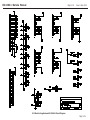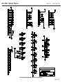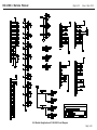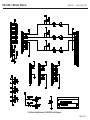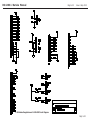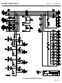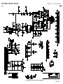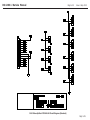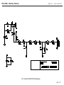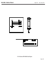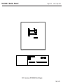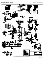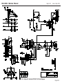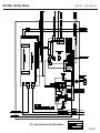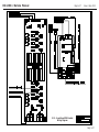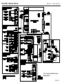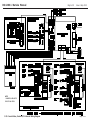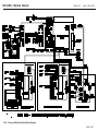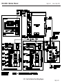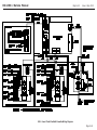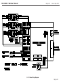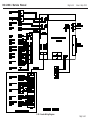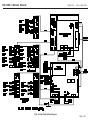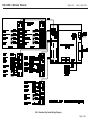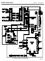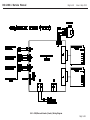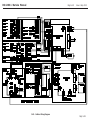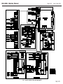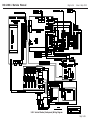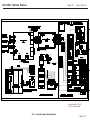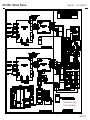
1
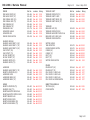
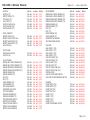
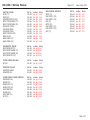
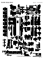
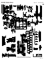
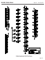
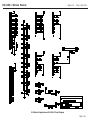
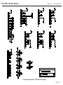
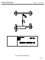
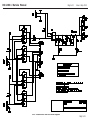
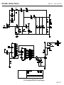
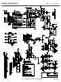
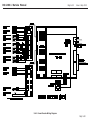
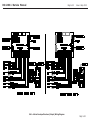
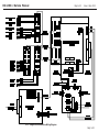
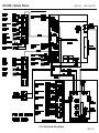
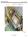
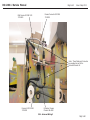
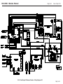
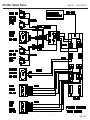
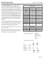
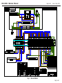
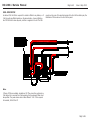
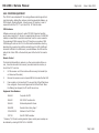
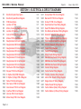
DS-1200 G3 Service Manual
Page 5-1
Issue 1 Sep 2013
SECTION 5 - ELECTRICAL & CIRCUIT DIAGRAMS
5-1
5-2
5-3
5-4
5-5
5-6
5-7
5-8
5-9
5-10
5-11
5-12
5-13
5-14
5-15
5-16
5-17
5-18
5-19
5-20
5-21
5-22
5-23
5-24
5-25
5-26
Electrical System Description
Electrical System Block Diagram
PCB Descriptions
Location of PCBs
Motors, Solenoids, Switches & Fuses
Location of Sensors
Control/CPU PCB Circuit Diagram
Module PCB Circuit Diagram
Daughterboard A Circuit Diagram
Daughterboard B Circuit Diagram
Daughterboard C Circuit Diagram
Daughterboard D Circuit Diagram
Daughterboard E Circuit Diagram
Daughterboard F Circuit Diagram
Daughterboard G Circuit Diagram
Daughterboard H Circuit Diagram
Distribution PCB Circuit Diagram
Stepper PCB Circuit Diagram
R. Splitter (Std) PCB C/Diagram
R. Splitter (Hi-Cap) PCB C/Diagram
Wetter PCB Circuit Diagram
Disc Sensor PCB Circuit Diagram
Vane Sensor PCB Circuit Diagram
Overflow PCB Circuit Diagram
Interlock PCB Circuit Diagram
Mains Delay PCB Circuit Diagram
Page 5-1
5.3
5.5
5.6
5.7
5.8
5.9
5.13
5.14
5.15
5.16
5.17
5.18
5.19
5.20
5.21
5.22
5.23
5.24
5.25
5.26
5.27
5.28
5.29
5.30
5.31
5.32
5-27
5-28
5-29
5-30
5-31
5-32
5-33
5-34
5-35
5-36
5-37
5-38
5-39
5-40
5-41
5-42
5-43
5-44
5-45
5-46
5-47
5-48
5-49
5-50
Hi-Cap Motor PCB Circuit Diagram
Barcode I/F PCB Circuit Diagram
Online I/F PCB Circuit Diagram
Head Electrical Panel Wiring Diagram
Head PSU Bracket Wiring Diagram
Env. Module & Handover Wiring Diagram
Kicker & Franker I/F Wiring Diagram
T/Over & Wetter/Closer Wiring Diagram
Track Electrical Panel Wiring Diagram
Shuttle & Cassette Wiring Diagram
Folder Wiring Diagram
Feeder Wiring Diagram
HiCap Feeder Wiring Diagram
Standard-Cap Feeder Wiring Diagram
OMR/Barcode Folder Wiring Diagram
OMR/Barcode Feeder Wiring Diagram
Collator Wiring Diagram
Forms Diverter Wiring Diagram
First Env. Diverter Wiring Diagram
Add-on Env. Diverter Wiring Diagram
Single Online I/F Wiring Diagram
Flatbed Feeder Wiring Diagram
Vertical Stacker (Main) Wiring Diagram
Vertical Stacker (U/Panel) Wiring Diagram
5.33
5.34
5.35
5.36
5.37
5.38
5.39
5.40
5.41
5.42
5.43
5.44
5.45
5.46
5.47
5.48
5.49
5.50
5.51
5.52
5.53
5.54
5.55
5.56
Page 5-1
DS-1200 G3 Service Manual
Page 5-2
Issue 1 Sep 2013
SECTION 5 - ELECTRICAL & CIRCUIT DIAGRAMS - CONTINUED
5-51
5-52
5-53
5-54
5-55
5-56
5-57
5-58
5-59
Autoread Camera Wiring Diagram
Autoread + Static Camera Wiring Diagram
Autoread Wiring 1
Autoread Wiring 2
Dual Output Thickness Checker
Pivoting Conveyor Wiring Diagram
Mains Distribution DIN Rail
Add-on PSU
Computer Equipment
5.57
5.58
5.59
5.60
5.61
5.62
5.63
5.65
5.66
Page 5-2
DS-1200 G3 Service Manual
5.1
Page 5-3
Issue 1 Sep 2013
ELECTRICAL SYSTEM DESCRIPTION
Incoming AC power is supplied to an electrical panel located at the front of
the insert head, and also each pair of stations. A switch mode power supply on the back of the panels supplies 36VDC and 8VDC to distribution PCBs
located on the front of the panels, which then supply these outputs to the
various parts of the machine. Other PCBs are also located on the electrical
panels and elsewhere on the machine. PCB descriptions follow further in
this section.
Communication between the PC and CPU PCBs is via a Controller Area Network (CAN) allowing simple twisted pair connection operating with a unique
protocol. The system has high immunity to noise and provides error-free
communication at up to 1Mbit/sec. It is widely used in industrial control applications.
DC hybrid motors are used to drive the turnover, feeders, folders, collator,
Hi/Std Cap feeders and diverter. They are connected to a module PCB for
their power.
Fig. 2
Station Electrical Panel
The electrical panels are shown below and opposite:
(located in front of each pair of stations)
Important Note: An Add-On PSU assembly 184-156 which includes
an additional Distribution PCB is used if a collator is fitted to any
station, or if 2 Hi-Cap units are fitted together on the same station
pair. The PSU is fitted to the rear of the panel with the Distribution
PCB on the front, as shown above. See also section 5.23.
PCB Description
A number of different PCB types are used on the machine, listed below:
Fig. 1
Insert Head Electrical Panel
(located below the Wetter/Closer)
Control PCB 180-676
CPU PCB 180-713 (Part of Control PCB)
Dual Distribution PCB
180-808
Module PCB
180-811 & 180-812
Daughterboard A
180-813
Daughterboard B
180-814
Daughterboard C
180-815
Daughterboard D
180-816
Note: Daughterboards
A to H are mounted on
Module PCBs and take
the place of separate
Splitter PCBs.
cont.
Page 5-3
DS-1200 G3 Service Manual
Page 5-4
Issue 1 Sep 2013
PCB Description (contd.)
Daughterboard E
180-817
Daughterboard F
180-818
Daughterboard G
180-819
Daughterboard H
180-820
Stepper PCB
180-675
Ribbon Splitter 1
180-691
Wetter PCB
180-702
Disc Sensor PCB
180-689
Vane Sensor PCB
180-692
Overflow PCB
180-714
Interlock PCB
180-709
Mains Delay PCB
180-710
Note: Daughterboards
A to H are mounted on
Module PCBs and take
the place of separate
Splitter PCBs.
Note: Mains Delay PCB is part of Mains Delay Kit 184-159
and is used only for machines over 4 stations, ie. 1 off kit fitted to station
pair 5 & 6, 1 off kit to stations 7 & 8 etc. Note also that DIP switch S1 on
Mains Delay PCB must be set to correspond with the station pair that the
PCB is fitted to, starting from 5/6 - ie. for station pair 5/6, set switch 1 to
ON with remaining seven set to OFF, for station pair 7/8, set switch 2 to ON
with remaining seven set to OFF and so on.
In addition there are 2 further PCBs used only in the Hi/Std Cap feeder or
Diverter:
Hicap Motor PCB
180-701
Ribbon Splitter 2
180-704
The following PCB is used only when a barcode reading collator is fitted:
Barcode I/F PCB
180-711
A block diagram of PCB connectivity is shown on the following page.
Page 5-4
DS-1200 G3 Service Manual
Page 5-5
Issue 1 Sep 2013
SENSORS
RIBBON SPLITTER
PCB 180-691
RIBBON SPLITTER
PCB 180-691
14-WAY RIBBON CABLE
SENSORS
STEPPER
MOTOR
SOLENOID
SOLENOID
MODULE
PCB 180-812
MODULE
PCB 180-812
MODULE
PCB 180-812
STEPPER
PCB 180-675
SENSORS
HYBRID
MOTOR
5 MODULE PCBs SUPPORTED
SOLENOID
CONTROLLER AREA
PC CONTROL UNIT
NETWORK (CAN)
CPU PCB
180-713
SWITCH MODE
POWER SUPPLY
184-205
RS232 x 4
Note: Module, Stepper and Ribbon Splitter PCBs show possible connections.
These may vary depending upon location
and application of the PCB.
CONTROL
PCB 180-676
8VDC
36VDC
8VDC
DUAL
DISTRIBUTION
PCB 180-808
36VDC x 8 TO MODULE PCBs
12VDC x 1 TO REMOTE CONTROL UNIT
5.2 Electrical System Block Diagram
Page 5-5
DS-1200 G3 Service Manual
5.3
PCB DESCRIPTIONS
Control PCB 180-676
Provides interfacing and connections between the machine and the CPU
PCB, and also supplies the CPU with power. It provides connections for the
module PCBs (up to five), and also has four serial inputs used for testing
purposes. The control PCBs are mounted on the insert head and station
electrical panels (see Figs.1 & 2).
CPU PCB 180-713
Processes information received and transmitted through the control PCB.
It is located on connectors on the control PCBs, mounted on the electrical
panels (see Figs. 1 & 2).
Module PCB 180-811 (without heatsink), 180-812 (with heatsink)
Provides control outputs for stepper PCBs (up to two), solenoids (up to
eight) and one hybrid DC motor. It also has inputs for six adjustable sensors (TX/RX pairs) and six on/off sensors (TX/RX pairs). It is supplied with
36VDC from the distribution PCB via the interlock PCB. 5v for circuitry is
supplied by the control PCB via the comms lead. A module PCB is fitted to
the insert head electrical panel (see Fig. 1), and also to the folder, feeder,
Hi/Std Cap feeder, collator and diverter modules. The module PCB on the
electrical panel is connected to the turnover and wetter/closer modules.
Dual Distribution PCB 180-808
Page 5-6
Issue 1 Sep 2013
Interlock PCB 180-709
Interlocks for some modules, eg. feeders, can safely be controlled by software. Other, more safety-critical modules are hard-wired through the Interlock PCB for added protection and would operate even in the event of
software failure. Mounted on the head electical panel and front edge of each
station pair.
Ribbon Splitter PCB (180-691, 180-704 & 180-745)
This has no active components and serves to channel a number of separate
sensor or solenoid/clutch connectors into one ribbon cable for convenient
routing. This connects to another ribbon splitter which is then connected to
a nearby module PCB using the separate connectors (note that in the case
of Hi-Cap feeders, two of the Hi-Cap splitters A6 & A7 connect to the Hi-Cap
motor PCB). It is also possible to ‘daisy-chain’ ribbon splitters.
Each ribbon splitter can connect three TX/RX sensor pairs and four solenoids (180-691), except for the Hi/Std Cap feeder, which can connect five
TX/RX sensor pairs and two solenoids (180-704), and also the Feeder separator, which can connect five TX/RX sensor pairs and five solenoids (180745)
Wetter PCB
This is used to monitor the fluid level sensors in the wetter tank. It is located at the front edge of the wetter/closer module.
Takes DC input from the switch mode power supply (fitted on the back of
each electrical panel) and distributes outputs as follows: 8 x 36VDC outputs
(fused at 10A), 2 x 8VDC outputs and 1 x 12VDC output. Provides power to
control PCB (8VDC), module PCBs (36VDC) and the remote control receiver
(12VDC). The distribution PCB is mounted on the electrical panels (see Figs.
1 & 2).
Stepper PCB 180-675
Provides power to one stepper motor and also has inputs for four adjustable
sensors (TX/RX pairs) and two on/off sensors (TX/RX pairs). It is connected
to the module PCB which supplies its power. Each stepper motor on the machine has one stepper PCB, and these are fitted to the kicker (2 off), turnover eject, handover, shuttle, track cassettes and collator.
cont.
Page 5-6
DS-1200 G3 Service Manual
5.4
Page 5-7
LocationS of PCBs
Location and usages of Module PCBs
Control/CPU, Interlock and Module PCBs are fitted on the insert head electrical panel (see Fig. 1). The Distribution and Hybrid E PCBs are fitted to the
head PSU bracket (to the right of the electrical panel (one on each side). An
Interlock PCB and Mains Delay PCB (when used) is fitted to the front edge
of the station pair, as is a Module PCB for each station. The wetter PCB is
fitted to the wetter/closer as described above. All other PCBs are fitted in
various modules on the machine and are shown in the exploded views in
this manual. The views that show them are referenced below:
Module PCB
Insert Head
Sect. 5.1
Track Pair
Sect. 5.2
Folder
Sect. 4c.5
Feeder
Sect. 4c.1
Flatbed Feeder
Sect. 4g.1
Hi-Cap Feeder
Sect. 4c.9
Std-Cap Feeder
Sect. 4c.41
I.S. Collator
Sect. 4c.18
Diverter
Sect. 4c.28
Vertical Stacker
Sect. 4j.16
Stepper PCB
Shuttle
Sect. 4b.1
Kicker
Sect. 4a.15
Track Cassette
Sect. 4b.8
Handover
Sect. 4a.8
Turnover Eject
Sect. 4a.13
I.S. Collator
Sect. 4.c.18
Vertical Stacker
Sect. 4j.4
Ribbon
Splitter PCB Various locations - see all drawings
Issue 1 Sep 2013
Module PCBs are identified by the letters A to E. They relate to different
modules on the machine, and their usages and locations are described below:
Module PCB ‘A’ – Feeder. Located underneath. Also used on Hi-Cap or StdCap feeder, located on a plate at the front, accessed from the rear.
Module PCB ‘B’ – Folder. Located on front of unit.
Module PCB ‘C’ – Handover. Located on side of Envelope Opener, adjacent
to Handover Unit. Also used on Collator, located on LH side.
Module PCB ‘D’ – Turnover and Wetter/Closer. Located on Insert Head
Electrical Panel (see page 3).
Module PCB ‘E’ – Kicker. Located on chassis to left of kicker. Also on track
pairs on front of chassis.
Page 5-7
DS-1200 G3 Service Manual
5.5
Issue 1 Sep 2013
Page 5-8
MOTORS, SOLENOIDS, MICROSWITCHES & FUSES
3-stack stepper motor:
Hybrid & Parvalux Motors
Handover
Sect. 4a.8
The hybrid motors fitted to the machine are used for main drive purposes.
They are 36VDC items, and incorporate an encoder (tacho) to provide
feedback to the software, so allowing timing operations to take place. There
are two types fitted, all but one used and shown in the exploded views as
follows:
Shuttle
Sect. 4b.1
T/over Eject Kicker
Sect. 4a.13
Kicker
Sect. 4a.15
Track Cassette
Sect. 4b.8
Turnover
Sect. 4a.11
1-stack stepper motor:
Feeders
Sect. 4c.1
Kicker
Sect. 4a.14
Folder
Sect. 4c.5
DC Motors
Collator
Sect. 4.c.18
Hi Cap Feeder
Sect. 4c.9
Std Cap Feeder
Sect. 4.c.39
Small DC (not hybrid) drive motors are used on the feeder for powering the
separator, and also providing drive to the feeder conveyor and feeder interface. They are also used with a cast gearbox for powering fold plates and
backstops. They can be located in the exploded views as follows:
The remaining type is used and shown in the exploded view as follows:
Wetter/Closer
Sect. 4a.18
The Hi Cap Feeder is also fitted with a 24v Parvalux motor for the hopper
lift. This connects to the Wetter PCB and is shown in the exploded view as
follows:
Hi Cap Feeder
Sect. 4c.9
Feeder (separator)
Feeder (conveyor drive)
Sect. 4c.1
Folder
Sect. 4c.5
Shuttle Bed
Hi-Cap (separator)
Sect. 4c.3
Sect. 4b.3
Sect. 4c.12
Stepper Motors
Solenoids
There are three types of stepper motor used on the machine and can be
located in the exploded views as follows:
Solenoids used on the machine are 25mm STA types except for one used on
the track cassette, which is a 19mm STA type. They can be located in the
exploded views as follows.
Double-ended stepper motor:
Turnover
Sect. 4a.11
Envelope Opener
Sect. 4a.1
Envelope Conveyor
Sect. 4a.4
Wetter/Closer
Sect. 4a.18
Track Cassette
Sect. 4b.8
Page 5-8
DS-1200 G3 Service Manual
Page 5-9
Issue 1 Sep 2013
Fuses
The mains supply of the machine is fitted with 30A & 10A 38mm cartridge
fuses, These are located on the DIN rail at the rear of the head section and
provide protection for the incoming mains (30A) and for all units on the machine (10A). See fig. 3 on page 64 for locations. Part numbers are:
30A
135-430
10A
135-410
The Distribution PCB is also fitted with on-board 10A fuses, part number
135-317UL. The PCBs are located at the front of the head section and each
track station (see figs. 1 & 2 on page 3).
5.6
LocationS of sensors
There are two types of sensor used on the machine, namely receiver/emitter optical pairs and flag or disc sensors, which contain the receiver & emitter in one block. The optical pairs may be used as adjustable sensors, (eg.
for double document detection where the opacity of the paper will affect the
output), or as on/off sensors (eg. for hold points).
Due to the large quantity of sensors used, it is not practical to show the
physical location of all on a single view, so each may be found separately
on the exploded view showing its actual position. Each sensor and its corresponding location is indicated on the following pages. Note that the sensor name shown is used uniformly throughout, on exploded views,
circuit diagrams and in software.
For each sensor, its part number, physical location and the wiring diagram
on which it appears is shown. The part number refers to the sensor and
cable assembly, including connector, as far back as the PCB to which it
connects. An exception to this is disc sensors which consist of a small PCB
holding the forked sensor, and a separate cable; the nimber shown is the
PCB number.
In the majority of cases, the sensors connect to a splitter PCB, but some
connect directly to a stepper or module PCB, or to the daughterboard located on the module PCB.
See also page 7 for locations and usages of Module PCBs.
Page 5-9
DS-1200 G3 Service Manual
FEEDER
Part No. Location Wiring
FEED HOLD POINT (RX)
182-444 Sec. 4c.1 5.38
FEED HOLD POINT (TX)
182-443 Sec. 4c.1 5.38
FEED DOUBLE DOC (RX)
182-442 Sec. 4c.1 5.38
FEED DOUBLE DOC (TX)
182-443 Sec. 4c.1 5.38
FEED DESKEW (RX)
182-444 Sec. 4c.1 5.38
FEED DESKEW (TX)
182-443 Sec. 4c.1 5.38
OVERGUIDE FLAG
180-776 Sec. 4c.1 5.38
SEPARATOR SHIELD 180-691 Sec. 4c.1 5.38
SEPARATOR GAP
180-691 Sec. 4c.1 5.38
FEEDER COVER SWITCH
182-418 Sec. 4c.1 5.38
ENVELOPE MODULE
ENVELOPE HOLD POINT 1 (RX)
182-444 Sec. 4a.1 5.32
ENVELOPE HOLD POINT 1 (TX)
182-440 Sec. 4a.1 5.32
ENVELOPE HOLD POINT 2 (RX)
182-441 Sec. 4a.1 5.32
FLAP DETECT (RX)
182-445 Sec. 4a.1 5.32
FLAP DETECT (TX)
182-443 Sec. 4a.1 5.32
NO FLAP DIVERT (RX)
182-444 Sec. 4a.1 5.32
NO FLAP DIVERT (TX)
182-443 Sec. 4a.1 5.32
ENVELOPE ENTRY (RX)
182-441 Sec. 4a.1 5.32
ENVELOPE ENTRY (TX)
182-440 Sec. 4a.1 5.32
HANDOVER
ENVELOPE HOLD POINT 2 (TX)
182-443 Sec. 4a.8 5.32
INSERT IN POSITION (RX)
182-445 Sec. 4a.8 5.32
HANDOVER CLOCK
180-689 Sec. 4a.8 5.32
HANDOVER INDEX (RX)
182-441 Sec. 4a.8 5.32
HANDOVER INDEX (TX)
182-437 Sec. 4a.8 5.32
KICKER
INSERT IN POSITION (TX)
182-443 Sec. 4a.155.33
ENVELOPE FLAP (TX)
182-443 Sec. 4a.155.33
INSERT BACKSTOP HOME FLAG
180-692 Sec. 4a.155.33
INSERT BACKSTOP MOTOR CLOCK
182-689 Sec. 4a.155.33
INSERT FINGERS FLAG 180-689 Sec. 4a.155.33
INSERT KICKER CLOCK
180-689 Sec. 4a.155.33
INSERT KICKER INDEX (RX)
182-442 Sec. 4a.155.33
INSERT KICKER INDEX (TX)
182-440 Sec. 4a.155.33
Page 5-10
Issue 1 Sep 2013
TURNOVER EJECT
Part No. Location Wiring
TURNOVER COMPLETE (TX)
182-440 Sec. 4a.115.34
TURNOVER EJECT CLOCK
180-689 Sec. 4a.115.34
TURNOVER EJECT INDEX (RX)
182-441 Sec. 4a.115.34
TURNOVER EJECT INDEX (TX)
182-440 Sec. 4a.115.34
TURNOVER
ENVELOPE FLAP (RX)
182-439 Sec. 4a.115.34
TURNOVER COMPLETE (RX)
182-445 Sec. 4a.115.34
TURNOVER BACKSTOP CLOCK FLAG 180-692 Sec. 4a.115.34
ENVELOPE FLAP CLOCK FLAG
180-689 Sec. 4a.115.34
TURNOVER COVER SWITCH
182-333 Sec. 4a.115.34
WETTER CLOSER
TANK DETECTOR
182-478 Sec. 4a.195.34
OVERFLOW REED SWITCH
182-675 Sec. 4a.195.34
CLOSER (RX)
182-441 Sec. 4a.185.34
CLOSER (TX)
182-443 Sec. 4a.185.34
EJECT (RX)
182-444 Sec. 4a.185.34
EJECT (TX)
182-443 Sec. 4a.185.34
WETTER COVER SWITCH
182-417 Sec. 4d.1 5.34
FOLDER
FOLDER EXIT (RX)
182-444 Sec. 4c.5 5.37
FOLDER EXIT (TX)
182-443 Sec. 4c.5 5.37
FOLD PLATE 1 CLOCK FLAG 180-692 Sec. 4c.5 5.37
FOLD PLATE 2 CLOCK FLAG
180-692 Sec. 4c.5 5.37
FOLD PLATE 3 CLOCK FLAG
180-692 Sec. 4c.5 5.37
FOLD PLATE 1&3 MICROSWITCH
131-130 Sec. 4c.5 5.37
INSERT TRACK MODULE
TOP TRACK (RX) 182-445 Sec. 4b.115.36
COVER SWITCH
182-494 Sec. 4d.7 5.36
Page 5-10
DS-1200 G3 Service Manual
SHUTTLE
Part No. Location Wiring
SHUTTLE (TX)
182-440 Sec. 4b.1 5.36
BOTTOM TRACK (TX)
182-440 Sec. 4b.1 5.36
TOP TRACK (TX)
182-440 Sec. 4b.1 5.36
HALF STEP (TX)
182-443 Sec. 4b.1 5.36
SHUTTLE CLOCK FLAG
180-689 Sec. 4b.1 5.36
SHUTTLE INDEX (RX)
182-438 Sec. 4b.1 5.36
SHUTTLE INDEX (TX)
182-440 Sec. 4b.1 5.36
TRACK CASSETTE
BOTTOM TRACK (RX) 182-445 Sec. 4b.8 5.36
INSERT TRACK CLOCK FLAG
182-689 Sec. 4b.8 5.36
INSERT TRACK INDEX (RX)
182-445 Sec. 4b.8 5.36
INSERT TRACK INDEX (TX)
182-437 Sec. 4b.8 5.36
HALF STEP (RX)
182-442 Sec. 4b.8 5.36
SHUTTLE BED
TRACKGUIDE CLOCKS
180-692 Sec. 4b.3 5.36
SHUTTLE (RX)
182-439 Sec. 4b.3 5.36
HI-CAP FEEDER
FEEDER HOLD POINT SENSOR (RX)
182-441 Sec. 4c.9 5.39
FEEDER HOLD POINT SENSOR (TX) 182-440 Sec. 4c.9 5.39
FEEDER DOUBLE DOC SENSOR (RX) 182-438 Sec. 4c.9 5.39
FEEDER DOUBLE DOC SENSOR (TX)
182-440 Sec. 4c.9 5.39
FEEDER DESKEW (RX) 182-441 Sec. 4c.9 5.39
FEEDER DESKEW (TX)
182-440 Sec. 4c.9 5.39
EXIT (RX)
182-441 Sec. 4c.9 5.39
EXIT (TX) 182-440 Sec. 4c.9 5.39
STACK SENSOR (RX) 182-445 Sec. 4c.9 5.39
STACK SENSOR (TX) 182-443 Sec. 4c.9 5.39
TRAY DOWN SWITCH 182-479 Sec. 4c.9 5.39
SEPARATOR GAP CLOCK 180-691 Sec. 4c.9 5.39
TOP LIMIT SENSOR
182-502 Sec. 4c.145.39
OVER RUN SENSOR (RX)
182-445 Sec. 4c.9 5.39
OVER RUN SENSOR (TX)
182-443 Sec. 4c.9 5.39
TOP COVER REED SWITCH
182-580 Sec. 4c.9 5.39
BOTTOM LIMIT SENSOR
182-480 Sec. 4c.145.39
TROLLEY-IN REED SWITCH 182-494 Sec. 4c.9 5.39
MOTOR CLOCK SENSOR A 180-689 Sec. 4c.9 5.39
MOTOR CLOCK SENSOR B
180-689 Sec. 4c.9 5.39
Page 5-11
Issue 1 Sep 2013
ST-CAP FEEDER
Part No. Location Wiring
FEEDER HOLD POINT SENSOR (RX)
182-441 Sec. 4c.395.40
FEEDER HOLD POINT SENSOR (TX)
182-440 Sec. 4c.395.40
FEEDER DOUBLE DOC SENSOR (RX) 182-438 Sec. 4c.395.40
FEEDER DOUBLE DOC SENSOR (TX)
182-440 Sec. 4c.395.40
FEEDER DESKEW (RX)
182-441 Sec. 4c.395.40
FEEDER DESKEW (TX)
182-440 Sec. 4c.395.40
EXIT (RX)
182-441 Sec. 4c.395.40
EXIT (TX)
182-440 Sec. 4c.395.40
STACK SENSOR (RX)
182-445 Sec. 4c.395.40
STACK SENSOR (TX)
182-443 Sec. 4c.395.40
SEPARATOR GAP SENSOR
180-691 Sec. 4c.395.40
TOP COVER REED SWITCH 182-580 Sec. 4c.395.40
COLLATOR
HOLD POINT 1 (RX)
182-445 Sec. 4c.185.43
HOLD POINT 1 (TX)
182-443 Sec. 4c.185.43
HOLD POINT 2 (RX)
182-445 Sec. 4c.185.43
HOLD POINT 2 (TX) 182-443 Sec. 4c.185.43
COLLATE POCKET (RX) 182-445 Sec. 4c.21b5.43
COLLATE POCKET (TX) 182-443 Sec. 4c.21b5.43
COLLATE EJECT (RX) 182-441 Sec. 4c.185.43
COLLATE EJECT (TX) 182-443 Sec. 4c.185.43
COLLATE TRACK PAWL (RX) 182-442 Sec. 4c.21b5.43
COLLATE TRACK PAWL (TX)
182-443 Sec. 4c.21b5.43
STEPPER CLOCK 180-689 Sec. 4c.21b5.43
COLLATE COVER REED SWITCH 182-494 Sec. 4c.185.43
COLLATOR IN POSITION REED SWITCH 182-494 Sec. 4c.215.43
DIVERTER
DIVERT ENTRY (RX) 182-444 Sec. 4c.285.44
DIVERT ENTRY (TX) 182-443 Sec. 4c.285.44
DIVERT EXIT (RX) 182-441 Sec. 4c.285.44
DIVERT EXIT (TX)
182-443 Sec. 4c.285.44
DIVERT 1 (RX)
182-441 Sec. 4c.285.44
DIVERT 1 (TX) 182-340 Sec. 4c.285.44
DIVERT 2 (RX)
182-344 Sec. 4c.285.44
DIVERT 2 (TX)
182-443 Sec. 4c.285.44
DIVERT COVER REED SWITCH 182-580 Sec. 4c.285.44
Page 5-11
DS-1200 G3 Service Manual
Page 5-12
VERTICAL STACKER
ENTRY (TX)
ENTRY (RX)
CONVEYOR DRIVE (TX/RX) INPUT STEPPER INDEX (TX)
INPUT STEPPER INDEX (RX)
SIDE GUIDE (TX/RX) SIDE GUIDE INDEX SIDE GUIDE CLOCK
INPUT STEPPER CLOCK
WHEEL CLOCK
WHEEL INDEX (TX)
WHEEL INDEX (RX)
Part No.
182-443
182-445
117-240
182-440
182-442
182-761
180-691
180-691
180-689
180-689
182-440
182-445
Location
Sec. 4j.1
Sec. 4j.8
Sec. 4j.2
Sec. 4j.4
Sec. 4j.4
Sec. 4j.8
Sec. 4j.5
Sec. 4j.5
Sec. 4j.4
Sec. 4j.7
Sec. 4j.3
Sec. 4j.3
Wiring
5.49
5.49
5.49
5.49
5.49
5.49
5.49
5.49
5.49
5.49
5.49
5.49
OMR/BARCODE READER
OMR FOLDER EXIT(TX)
OMR FOLDER DESKEW (TX)
OMR FOLDER DESKEW (RX) OMR FOLDER EXIT (RX)
Part No.
182-443
182-443
182-444
182-341
Location Wiring
Sec. 4c.335.41
Sec. 4c.335.41
Sec. 4c.335.41
Sec. 4c.335.41
FLATBED FEEDER MAIN ASSY
EXIT(TX)
Part No.
182-440
Location Wiring
Sec. 4g.1 5.48
SEPARATOR (FB) ASSY
SEPARATOR SHIELD
SEPARATOR GAP
Part No.
180-691
180-691
Location Wiring
Sec. 4g.8 5.48
Sec. 4g.8 5.48
FLATBED FEEDER CHASSIS ASSEMBLY
OVERGUIDE FLAG
DESKEW (TX)
DOUBLE DOC (TX)
DOUBLE DOC (RX)
HOLD POINT (RX)
DESKEW (RX) HOLD POINT (TX)
EXIT (RX)
Part No.
182-643
182-443
182-443
182-445
182-444
182-444
182-443
182-445
Location
Sec. 4g.9
Sec. 4g.9
Sec. 4g.9
Sec. 4g.9
Sec. 4g.9
Sec. 4g.9
Sec. 4g.9
Sec. 4g.9
SINGLE ONLINE INTERFACE
ENTRY (TX)
HOLD POINT 1 (RX)
HOLD POINT 2 (RX) EXIT (RX)
ENTRY (RX)
HOLD POINT 1 (TX) HOLD POINT 2 (TX) EXIT (TX)
Part No.
182-443
182-444
182-444
182-445
182-444
182-443
182-443
182-443
Issue 1 Sep 2013
Location
Sec. 4h.1
Sec. 4h.1
Sec. 4h.1
Sec. 4h.1
Sec. 4h.1
Sec. 4h.1
Sec. 4h.1
Sec. 4h.1 Wiring
5.47
5.47
5.47
5.47
5.47
5.47
5.47
5.47
Wiring
5.48
5.48
5.48
5.48
5.48
5.48
5.48
5.48
Page 5-12
DS-1200 G3 Service Manual
Page 5-13
5.7 Control & CPU PCB 180-676 Circuit Diagram
Issue 1 Sep 2013
Page 5-13
DS-1200 G3 Service Manual
Page 5-14
5.8 Module PCB 180-811/812 Circuit Diagram
Issue 1 Sep 2013
Page 5-14
DS-1200 G3 Service Manual
Page 5-15
Issue 1 Sep 2013
5.9 Module Daughterboard A 180-813 Circuit Diagram
Page 5-15
DS-1200 G3 Service Manual
Page 5-16
Issue 1 Sep 2013
5.10 Module Daughterboard B 180-814 Circuit Diagram
Page 5-16
DS-1200 G3 Service Manual
Page 5-17
Issue 1 Sep 2013
5.11 Module Daughterboard C 180-815 Circuit Diagram
Page 5-17
DS-1200 G3 Service Manual
Page 5-18
Issue 1 Sep 2013
5.12 Module Daughterboard D 180-816 Circuit Diagram
Page 5-18
DS-1200 G3 Service Manual
Page 5-19
5.13 Module Daughterboard E 180-817 Circuit Diagram
Issue 1 Sep 2013
Page 5-19
DS-1200 G3 Service Manual
Page 5-20
Issue 1 Sep 2013
5.14 Module Daughterboard F 180-818 Circuit Diagram
Page 5-20
DS-1200 G3 Service Manual
Page 5-21
Issue 1 Sep 2013
5.15 Module Daughterboard G 180-819 Circuit Diagram
Page 5-21
DS-1200 G3 Service Manual
Page 5-22
Issue 1 Sep 2013
5.16 Module Daughterboard H 180-820 Circuit Diagram
Page 5-22
DS-1200 G3 Service Manual
Page 5-23
5.17 Distribution PCB 180-808 Circuit Diagram
Issue 1 Sep 2013
Page 5-23
DS-1200 G3 Service Manual
Page 5-24
5.18 Stepper PCB 180-675 Circuit Diagram
Issue 1 Sep 2013
Page 5-24
DS-1200 G3 Service Manual
Page 5-25
5.19 Ribbon Splitter PCB 180-691 Circuit Diagram (Standard)
Issue 1 Sep 2013
Page 5-25
DS-1200 G3 Service Manual
Page 5-26
Issue 1 Sep 2013
5.20 Ribbon Splitter PCB 180-704 Circuit Diagram (Hi-Cap Feeder)
Page 5-26
DS-1200 G3 Service Manual
Page 5-27
Issue 1 Sep 2013
5.21 - Wetter PCB 180-702 Circuit Diagram
Page 5-27
DS-1200 G3 Service Manual
Page 5-28
Issue 1 Sep 2013
5.22 - Disc Sensor PCB 180-689 Circuit Diagram
Page 5-28
DS-1200 G3 Service Manual
Page 5-29
Issue 1 Sep 2013
5.23 - Vane Sensor PCB 180-692 Circuit Diagram
Page 5-29
DS-1200 G3 Service Manual
Page 5-30
Issue 1 Sep 2013
5.24 - Overflow PCB 180-714 Circuit Diagram
Page 5-30
DS-1200 G3 Service Manual
Page 5-31
5.25 - Interlock PCB 180-709 Circuit Diagram
Issue 1 Sep 2013
Page 5-31
DS-1200 G3 Service Manual
Page 5-32
5.26 - Mains Delay PCB 180-710 Circuit Diagram
Issue 1 Sep 2013
Page 5-32
DS-1200 G3 Service Manual
Page 5-33
5.27 - Hi-Cap Motor PCB 180-701 Circuit Diagram
Issue 1 Sep 2013
Page 5-33
DS-1200 G3 Service Manual
Page 5-34
5.28 - Barcode Interface PCB 180-711 Circuit Diagram
Issue 1 Sep 2013
Page 5-34
DS-1200 G3 Service Manual
Page 5-35
5.29 - Single O/L Interface PCB 180-744 Circuit Diagram
Issue 1 Sep 2013
Page5-35
5-35
Page
DS-1200 G3 Service Manual
Page 5-36
Issue 1 Sep 2013
5.30 - Insert Head Electrical Panel Wiring Diagram
Page 5-36
5-36
Page
DS-1200 G3 Service Manual
Page 5-37
Issue 1 Sep 2013
5.31 - Insert Head PSU Bracket
Wiring Diagram
Page 5-37
DS-1200 G3 Service Manual
Page 5-38
Issue 1 Sep 2013
5.32 - Envelope Module & Handover
Wiring Diagram
Page 5-38
5-38
Page
DS-1200 G3 Service Manual
Page 5-39
Issue 1 Sep 2013
NOTE:
1. NUMBERS IN BRACKETS
DENOTE 1200 SERIES.
5.33 - Insert Kicker, Franker I/F & Remote Wiring Diagram
Page 5-39
DS-1200 G3 Service Manual
Page 5-40
Issue 1 Sep 2013
5.34 - Turnover & Wetter/Closer Wiring Diagram
Page 5-40
DS-1200 G3 Service Manual
Page 5-41
5.35 - Track Pair Electrical Panel Wiring Diagram
Issue 1 Sep 2013
Page 5-41
DS-1200 G3 Service Manual
Page 5-42
Issue 1 Sep 2013
5.36 - Insert Track Shuttle & Cassette Wiring Diagram
Page5-42
5-42
Page
DS-1200 G3 Service Manual
Page 5-43
5.37 - Folder Wiring Diagram
Issue 1 Sep 2013
Page 5-43
DS-1200 G3 Service Manual
Page 5-44
5.38 - Feeder Wiring Diagram
Issue 1 Sep 2013
Page 5-44
DS-1200 G3 Service Manual
Page 5-45
5.39 - Hi-Cap Feeder Wiring Diagram
Issue 1 Sep 2013
Page 5-45
DS-1200 G3 Service Manual
Page 5-46
Issue 1 Sep 2013
5.40 - Standard-Cap Feeder Wiring Diagram
Page 5-46
DS-1200 G3 Service Manual
5.41 - OMR/Barcode Reader (Folder) Wiring Diagram
Page 5-47
Issue 1 Sep 2013
Page 5-47
DS-1200 G3 Service Manual
Page 5-48
5.42 - OMR/Barcode Reader (Feeder) Wiring Diagram
Issue 1 Sep 2013
Page 5-48
DS-1200 G3 Service Manual
Page 5-49
5.43 - Collator Wiring Diagram
Issue 1 Sep 2013
Page 5-49
DS-1200 G3 Service Manual
Page 5-50
5.44 - Forms Diverter Wiring Diagram
Issue 1 Sep 2013
Page 5-50
DS-1200 G3 Service Manual
5.45 - First Envelope Diverter (Output) Wiring Diagram
Page 5-51
Issue 1 Sep 2013
Page 5-51
DS-1200 G3 Service Manual
Page 5-52
5.46 - Add-on Envelope Diverters (Output) Wiring Diagram
Issue 1 Sep 2013
Page 5-52
DS-1200 G3 Service Manual
5.47 - Single On-line Interface Wiring Diagram
Page 5-53
Issue 1 Sep 2013
Page 5-53
DS-1200 G3 Service Manual
Page 5-54
5.48 - Flatbed Feeder Wiring Diagram
Issue 1 Sep 2013
Page 5-54
DS-1200 G3 Service Manual
Page 5-55
5.49 - Vertical Stacker (Main) Wiring Diagram
Issue 1 Sep 2013
Page 5-55
DS-1200 G3 Service Manual
Page 5-56
Issue 1 Sep 2013
5.50 - Vertical Stacker (Underpanel) Wiring Diagram
Page 5-56
DS-1200 G3 Service Manual
Page 5-57
Issue 1 Sep 2013
See also section 5.53 &
5.54 for wiring details.
5.51 - Autoread Camera Wiring Diagram
Page 5-57
DS-1200 G3 Service Manual
Page 5-58
Issue 1 Sep 2013
See also section 5.53 &
5.54 for wiring details.
5.52 - Autoread Camera + Static Camera Wiring Diagram
Page 5-58
DS-1200 G3 Service Manual
Autoread Camera
Page 5-59
KAB Firewire 90 DEG 0.5M
179-8480
Issue 1 Sep 2013
Note:- Cable supplied as part of
Autoread Camera Kit
Bulkhead
B2-1448-A
5.53 - Autoread Wiring 1
Page 5-59
DS-1200 G3 Service Manual
KAB Firewire 90 DEG 0.5M
179-8480
Page 5-60
Issue 1 Sep 2013
Firewire Connector 360 DEG
170-8590
Note:- These Cables and Connector
are supplied as part of the
Autoread Camera Kit
Firewire 4.5M 90 DEG
179-8580
Connector Firewire
Chassis 168-4850
5.54 - Autoread Wiring 2
Page 5-60
DS-1200 G3 Service Manual
5.55 - Dual Output Thickness Checker - Wiring Diagram V2
Page 5-61
Issue 1 Sep 2013
Page 5-61
DS-1200 G3 Service Manual
Page 5-62
5.56 - Pivoting Conveyor Wiring Diagram
Issue 1 Sep 2013
Page 5-62
DS-1200 G3 Service Manual
Page 5-63
5.57mains distribution (see also diagram overleaf)
Mains power for the 1200-G3 is distributed from DIN rail connectors located
behind the head unit, under the envelope opener. Incoming mains power is
delivered to a mains switch located behind the insert head. Output from the
mains switch then connects through 30A fuses to a number of 10A fuses for
connection to the insert head (unit 0) and station pairs (units 1 & 2, 3 & 4
etc.). If a greater number of stations than 12 is fitted, an add-on DIN rail is
fitted to provide further fused outputs. Important: Although all 10A fuses
are isolated by turning off the mains switch, power to the PC is not: this
is a separate supply that allows the PC to run for access to technical manuals and analysis tools, even when the main machine is isolated from the
power source.
The fuse blocks supplying the DIN rail fuses are capable of carrying no more
than 30A rated current (36A peak current). This means that dependent
upon the number of stations, and the units fitted to them, not all configurations are possible without exceeding maximum rated current.
The chart on the opposite details current rating of each unit to ensure the
maximum is not exceeded.
Note: the two end fuses on the main DIN rail are used by the conveyor,
which uses approx. 200W. These fuses can also be used in parallel with another station unit, but observe the overall current rating.
UNIT DESCRIPTION
Head
Track Pair
Insert Feeder
Std-Cap Feeder Folder
Hi-Cap Feeder Folder
Std-Cap Accumulator1
Hi-Cap Accumulator1
Vertical Stacker
Typical Sytem Total2
Max. Allowable Rated
Current
Any System
Max. Peak Current
Issue 1 Sep 2013
RATED CURRENT
@115v
6A
2A
2A
2A
2.5A
4A
5A
2A
25.5A
@230v
3A
1A
1A
1A
1.25A
2A
2.5A
1A
12.75A
30A
30A
PEAK CURRENT
Rated Current + 6A
36A
Rated Current + 3A
33A
¹ Std-Cap/Hi-Cap Collator comprises:
Collator Unit
OMR/Barcode Reader
Std-Cap/Hi-Cap Feeder
Folder
2-Bin Divert
² Typical system (8 station) comprises:
115v
230v
Head
Qty. 1
6A
3A
2 Stn. Module
Qty. 4
8A
4A
Feeder
Qty. 5
10A
5A
Std-Cap Folder
Qty. 1
2A
1A
Hi-Cap Folder
Qty. 1
2.5A
1.25A
Hi-Cap Collator
Qty 1 5A
2.5A
33.5A
14.3A
Page 5-63
DS-1200 G3 Service Manual
4
2
Issue 1 Sep 2013
6
5
3
1
Page 5-64
Fig. 3 - Mains DIN Rail
Page 5-64
DS-1200 G3 Service Manual
Page 5-65
Issue 1 Sep 2013
5.58 ADD-ON PSU
An add-on PSU 184-156 is required if a collator is fitted to any station, or if
2 Hi-Cap units are fitted together on the same station. A second Distribution PCB 180-684 is also required, and this is supplied in the kit. The PSU
mounts on the rear of the electrical panel at the front of the station pair, the
Distribution PCB mounts on the front of the panel.
Note:
2 Types of PSU are available, Lambda and XP. They cannot be combined, so
if an add-on kit is required for a field upgrade, the type already fitted must
be specified. The power-share cable is also different - 182-704 is required
for Lambda, 182-633 for XP.
Page 5-65
DS-1200 G3 Service Manual
Page 5-66
Issue 1 Sep 2013
5.59 COMPUTER EQUIPMENT
The 1200 G3 uses a standard PC for running software and storage of technical information, datalog files, archives and other associated software, eg.
PICS Integrity Checking System. A touch-screen LCD monitor is used in
conjunction with the PC, 17” up to late 2006, 19” after this date.
CAN Hardware
Software versions up to Version 5 used a PCI CAN (Computer Area Network) device inside the PC. Version 5 onwards allows the use of a USB CAN
instead, and was fitted to production machines from this version onwards.
If a replacement CAN is required from a PCI machine, a procedure ‘USB
CAN Setup.pdf’ exists on the PC in the Technical Documentation directory,
describing the procedure for installing and setting up the CAN. A different
terminator is fitted to the USB device, conncted between the CAN and the
cable to the Control PCB on the electrical panel at the front of the inserter
head.
Remote Control
If a hand-held transmitter is replaced, or other communication failure occurs, it must be retuned to the receiver (mounted inside the machine, in
front of the PC. To do this:
1.
Lift the receiver out of the machine after removing the bracket (do
not disconnect the cable).
2.
Remove the receiver cover and press SW2 to illimunate the Red LED.
3.
Press a switch on the hand-held TX once and the LED will flash twice
then extinguish. Press a switch again and the LED will flash. When
the flashing has stopped, the TX and RX are in tune.
Equipment Item Numbers
184-642
Computer A5 ATX
184-650
ELO 1915L Touchmonitor
184-645
Wireless Keyboard & Mouse
184-6990
Remote Control Assy Viper*
179-A0008176
Startech 4 Port PCI Card
179-781
Sub D9 CAN Terminator
* Includes, TX, RX and mounting bracket. Spare control panel overlays can
be obtained by ordering G3-0547-A for 184-6990.
Page 5-66