1
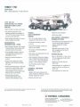
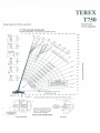
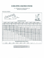
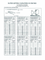
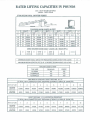
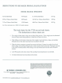
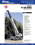
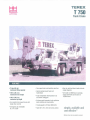
TEREX
T750
LIFTING
Truck Crane
FEATURES
- 75 ton (68 mt)
maximum lifting capacity
-126 fl. (38.4 m)
maximum boom length
-192 fl. (58.5 m)
maximum lip height
• Four-section full power boom with
single lever control
• SWingaway jib offsettable
0°, 1yo or 30°
• Two-speed main and auxiliary winches
• QUick-reeving boom head and
hook block
• Fully independent multi-position out
and down outriggers
• Easy to read load chart books include
range diagrams
• 12-month or 2000 hours warranty,
major weldments are 5-years or
10,000 hours
• Environmental operator's cab optimizes
load visibility and productivity
• Travel speeds to 55 mph (88 km/h)
• Tight 42 ft. 9 in. (13 m) turning radius
simple, available and
cost effective""
Machines shown may have optional equipment.
TEREX T 750
Truck Crane
Max. Lifting Capacity: 75 tons (68 mt)
126 ft. (38.4 m)
FOUR-SECTION, FULL-POWER
BOOM WITH SINGLE LEVER
CONTROL
• High strength, four plate construction.
• Two double-acting boom hoist
cylinders provide boom elevation of
_2° to 78° for easier reeving changes
and close radius operation.
RUGGED,
EASY-TO-MANEUVER
CARRIER
• Quick-reeving boom head; no need to
remove wedge from socket.
'10 ft. (3 m) wide chassis is Terex
designed and built with 8 x 4 drive.
ENVIRONMENTAL
OPERATOR'S CAB - UPPER
• Full aluminum decking, fenders
and rims.
• Rated Capacity Indicator (RCI) system
including anti-two block system with
automatic function disconnects.
• Fully adjustable operator's seat has
shock-absorbing suspension and
adjustable arm rests.
• Sound and weather insulated for
comfort.
• Hinged tinted skylight and sliding
right-hand, rear and door windows,
roof wiper.
• Armrest mounted joystick or twin lever
controls for swing, auxiliary winch,
main winch and boom hoist; foot
control pedals for swing brake, boom
telescope and engine throttle.
• Complete instrumentation.
Environmentally-sealed rocker
switches. Circuit breakers in cab.
• Electronic drum indicators.
• Winch drum rollers.
HIGH CAPACITY, DEPENDABLE
HYDRAULIC SYSTEM
• Two tandem gear-type pumps driven off
front of carrier engine. Combined
system capability is 158 gpm
(598 Ipm).
• Ground level outrigger controls are
built into rear fenders.
'13 forward, 2 reverse RoadRanger
transmission.
• Hydraulic reservoir with 177 gal.
(615 I) capacity and full flow oil
filtration system.
• Dual circuit, air self-adjusting front and
rear service brakes.
OPTIONS INCLUDE:
• Fully independent hydraulic outriggers
may be utilized fully extended to 23 ft.
7.5 in. (7.2 m), in their mid extended
position or fully retracted positions.
• 414 HP (309 kw) Detroit Diesel
S60 engine.
• 38 ft. or 38 to 60 ft. (11.6 or 11.6 to
18.3 m) swingaway jib. Both offset
0°, 1r or 30°,
• Auxiliary winch with rope and
drum roller.
• Heater/defroster, air conditioner for
operator's cab; air conditioner for
carrier cab.
POWERFUL, TWO-SPEED
WINCHES
• Cold weather kit for carrier cab.
• 456 fpm (181 mpm) maximum line
speed, 20,400 Ibs. (9250 kg) maximum
line pull. Single lever control.
• Integral automatic brake.
For more information, product demonstration, or details on purchase. lease and rental
plans, please contact your local Terex Cranes Distributor.
We reserve the right to amend these specifications at any time without notice. The only
warranty applicable is our standard writlen warranty applicable to the particular product
and sale, We make no other warranty, expressed or implied.
~TEREX
CRANES
Highway 501 East/P.O. Box 260002
Conway, SC 29528-6002 USA
(843) 349-6900' FAX: (843) 349-7090
E-mail: [email protected]
TC-509
©Terex Cranes, Inc. 2000
Litho in U.S.A.
Gw.terexlift.c00
_
-
10Ul00T34
TEREX
T750
Truck Crane
7S Ton Capacity
Range diagram & lifting capacities
T 750 RANGE DIAGRAM
RANGE DIAGRAM T 750 126' FULL POWER BOOM
o
10
20
30
40
50
60
70
80
90
100
110
120
130
140
200
78"
75'
190
180
170
160
150
140
130
120
110
100
90
80
tuw
li-
D
z:::>
oa:
o
w
70
60
>
oco
«
f-
I
o
W
I
WARNING
CONSULT MACHINE RATING PLATE
FOR BOOM LENGTHS, BOOM
ANGLES. AND RADII WHERE A
TIPING CONDITION MAY OCCUR
~=====-
5'-
20
10
20
30
40
50
GROUND LEVEL
60
70
80
90
0
100
110
120
130
HOOK DISTANCE FROM CENTER LINE OF ROTATION· FEET
NOTE: These lines determine
the limiting position of any
load lor operating within
working area~ indicated.
AREAS OF OPERATION
ON OUTRIGGERS
ON TIRES
140
RATED LIFTING CAPACITIES IN POUNDS
40.5 -126 FT BOOM ON FULLY EXTENDED OUTRIGGERS - 360 0
9700 POUND TOTAL COUNTERWEIGHT
9700 POUND TOTAL COUNTERWEIGHT
~~rt~
O~'"
2ND....
1ST
BASE
0
_
~
k
D EDUCTIONS
HORIZONTAL
'-- LOAD
4C .5 FT
lOADED
LOAD. LB
BOOM
RADIUS
FT.
ANGLE
Z4:
sIDe
10
12
15
20
25
30
35
40
45
50
55
60
65
70
75
BO
B5
90
95
100
68
150000
116000
92500
69600
55600
44500
65
60
51
41
28
55 FT
4f FT
LOADED
LOADED
LOAD. LB
BOOM
ANGLE
ANGLE
Z4:
71
68
64
56
48
3B
25
SIDE
Z4:
SIDE
102000
100000
91700
69500
55200
44700
34BOO
74
72
69
95000
94700
89000
69000
54600
45100
35400
27300
2160
63
57
50
43
34
22
75 FT
6f FT
LOAD. LB
BOOM
LOADED
800M
ANGLE
LOAD. LB
LOADED
BOOM
A~E
SIDE
Z4:
75
73
77800
73200
64000
54000
45000
35400
27600
21900
17700
14400
68
63
5B
52
46
39
31
21
75
71
67
63
5B
54
4R
43
37
LOAD. LB
95 FT
LOADGO
LOAD. LB
BOOM
I\NGI.E
SIDE
29
61000
55700
4B5oo
44500
35000
27Roo
22100
17900
14700
12100
19
tOooo
SiDE
Z4:
74
70
67
63
5Q
55
50
46
40
35
28
18
BOOM
ANGLF.
LOAD. LB
Z4:
SIDE
I
I
'3000
134.01
I
0
I
lB700
(3B.51
I
0
I
1230U
14B.S1
I
Bn
56
52
4B
43
38
33
2B
17
I
B600
(5B.51
I
0
I (~~ I
0
I
4700
178.51
I
0
I
3200
18B.51
MIN. BOOM ANGLE (DEG) FOR INDICATED BOOM LENGTH (NO LOAD)
MAX. BOOM LENGTH (FEET) AT ·2 DEGREE BOOM ANGLE (NO LOAD
Z4:
SIDE
75
72
69
66
63
60
57
53
49
46
41
37
31
25
I
LOAD. LB
BOOM
1? FT
I
0
198 51
I
2B2oo
25400
23100
21000
19200
17500
15200
12600
10500
B700
7300
6000
5000
4000
3200
2400
I
BOOM
LOAD. LB
Z4:
SIDE
LOAD
RADIUS
ANGLE
SJOF
77
74
72
69
66
64
61
57
54
51
47
44
40
35
30
24
31600
2BBOO
25800
23200
01000
18300
15100
12500
10400
B700
7200
6000
4900
3900
3100
--
'" '" '"
LOADED
ANGLE
Z4:
40000
36300
32400
29500
26700
21000
lB300
15100
12000
10500
8BOO
7300
6100
5000
ZERO DEGREE BOOM ANGLE LOADS (LB) I (RADII (FT.»
0
LOADED
LOAD. LB
17
0
11 ,FT
1C 5 FT
lOAOl::O
BOOM
ANGLE
76
73
70
67
63
48200
42200
39000
33400
27200
22300
18100
14800
12300
10200
8400
7000
~
...
R5 FT
LOADED
I
~, "~, '''~,
POWERED BOOM LENGTH IN FEET
LOAD
Ilr
Ifll
0
1')(15
76
74
72
69
67
64
61
58
56
53
49
46
43
39
35
I
FT
10
12
15
20
25
30
35
40
45
50
55
60
65
70
75
80
85
90
22500
20500
18800
17100
15700
14800
12700
10600
B800
7400
6100
5000
4100
3300
2500
I
95
10
I
RATED LIFTING CAPACITIES IN POUNDS
126 FT BOOM FULLY EXTENDED
126 FT. BOOM PLUS EXTENSION
FULLY EXTENDED OUTRIGGERS· 360 0
9700 POUND TOTAL COUNTER WEIGHT
BOOM
!
'¢r
'
~
~~~NSION
~~
~
2 DEG EXT OFFSET WITH
STINGER RETRACTED
FOR BOOM LENGTHS
>128.0 FT· 164 FT
LOADED
BOOM
ANGLE
l:,;
77
75
74
72
70
RR
67
R<;
63
fiO
58
53
360°
11200
10<;00
9900
9300
RROO
8300
7800
7<100
6900
5ROO
4800
3200
40
45
50
55
60
65
70
7<;
80
RS
90
100
2 DEG EXT OFFSET WITH
STINGER EXTENDED
FOR BOOM LENGTHS
>150.0 FT -186 FT
LOADED
BOOM
ANGLE
l:,;
77
7fi
7<;
73
72
70
R8
67
65
fi4
fiO
<;R
<;1
FT.
FOR 164
FOOT
BOOM
ONLY
LOAD, LB
REF.
LOAD
RADIUS
FT.
3600
FOR 186
FOOT
BOOM
ONLY
7100
fiROO
RROO
R::IOO
6100
5700
5500
<;::100
5200
<;100
4ROO
::1::100
2200
45
50
<;5
60
65
70
7<;
RO
85
QO
.100
110
120
LOAD, LB
ITl1
~
17° OFFSET
17
DEG EXT OFFSET WITH
STINGER RETRACTED
FOR BOOM LENGTHS
>128.0 FT - 164 FT
LOADED
BOOM
ANGLE
Z+
77
75
73
72
70
68
66
64
61
56
51
17
8700
8400
8000
7700
7300
6900
6500
6200
5600
3800
2400
50
55
60
65
70
75
80
85
90
100
110
>1·50.0 FT - 186 FT
77
76
74
72
71
69
67
64
60
56
51
FT.
360 0
LOAD, LB
FOR BOOM LENGTHS
4
REF.
LOAD
RADIUS
FOR 164
FOOT
BOOM
ONLY
DEG EXT OFFSET WITH
STINGER EXTENDED
LOADED
BOOM
ANGLE
I
'~
W~'... ....~,~, ....~,~, ....~,~,
30° OFFSET
REF.
LOAD
RADIUS
II~~'
2° OFFSET
LOAD
LOAD, LB
360'
5000
4900
4600
4400
4200
4100
3900
3:- Jtj3400
2900
1900
REF.
LOAD
RADIUS
FT.
FOR 186
FOOT
BOOM
ONLY
60
65
70
75
80
85
90
100
110
120
130
30 DEG EXT OFFSET WITH
STINGER RETRACTED
FOR BOOM LENGTHS
>128.0 FT· 164 FT
LOADED
BOOM
ANGLE
Z+
77
75
74
72
70
68
66
63
59
53
360'
6800
6500
6400
6200
6000
5800
5700
5500
4300
2800
55
60
65
70
75
80
85
90
100
110
FOR BOOM LENGTHS
>150.0 FT -186 FT
Z+
77
76
74
72
70
67
63
59
54
REF.
LOAD
RADIUS
FT.
FOR 164
FOOT
BOOM
ONLY
LOAD, LB
30 DEG EXT OFFSET WITH
STINGER EXTENDED
LOADED
BOOM
ANGLE
'"
REF.
LOAD
RADIUS
FT.
360°
FOR 186
FOOT
BOOM
ONLY
3700
3600
3500
3300
3200
3100
3000
2700
2100
70
75
80
85
90
100
110
120
130
LOAD, LB
RATED LIFTING CAPACITIES IN POUNDS
40.5 - 75 FT BOOM ON TIRES
CREEP - OVER REAR
9700 POUND TOTAL COUNTER WEIGHT
...
eTUbiN~L- ~ Z+.m~
2ND
1~
BASE
0
--l...)"1
~~
ty
0
jl,.)C.\S
O,--SEo
DE Due-,ONS
+
HORIZONTAL
"'-LOAD
POWERED BOOM LENGTH IN FEET
40. :>FT
LOAD
RADIUS
FT
4 FT
LOADED
BOOM
ANGLE
LOAD. LB
L:
REAR
68
65
60
51
41
32600
29500
25500
20400
16300
10
12
15
20
25
LOADED
BOOM
ANGLE
Z:::
70
68
63
56
47
REAR
32300
29200
25400
20300
16300
LOADED
BOOM
ANGLE
LOAD. LB
Z:::
74
72
69
LOADED
BOOM
ANGLE
l4.
REAR
31600
28700
25000
20100
16200
63
57
7F
65 FT
5! FT
LOAD. LB
tUV
....',
....
75
72
67
62
LOAD. LB
REAR
28200
24600
19900
16100
LOADED
BOOM
ANGLE
l4.
75
71
67
"
"
FT
LOAD
LOAD, LB
RADIUS
REAR
FT.
10
12
15
20
25
24200
19600
15900
ZERO DEGREE BOOM ANGLE LOADS (LB) I (RADII (FT.»
0
9100
(34.0)
0
6700
(38.5)
0
3200
(48.5)
-
0
(58.5)
MINIMUM BOOM ANGLE (DEG) FOR INDICATED BOOM LENGTH (NO LOAD)
-2
MAXIMUM BOOM LENGTH (FEET) AT -2 DEGREE BOOM ANGLE (NO LOAD)
65
TIRE INFLATION CHART
TIRE SIZE
14.00R20
CREEP
105
115
120
ROADING
90
115
120
315/80R22.5
425/65R22.5
2080 MAIN & AUXILIARY HOIST REEVING 6 X 37
.75 INCH 19mm) DIAMETER ROPE BREAKING STRENGTH 58800 LB. (26600 KG)
PARTS OF LINE
1
2
3
4
5
6
7
8
9
10
MAXIMUM
LOAD·LBS.
15000
30000
45000
60000
75000
90000
105000
120000
135000
150000
MAXIMUM
LOAD·KGS.
6800
13600
20400
27200
34000
40800
47600
54400
61200
68100
HOIST REEVING 8 X 19 ROTATION RESISTANT
.75 INCH 19mm) DIAMETER ROPE BREAKING STRENGTH 51800 LB. (23500 KG)
PARTS OF LINE
1
2
3
4
5
6
7
8
9
10
MAXIMUM
LOAD·LBS.
10350
20700
31050
41400
51750
62100
72450
82800
93150
10.... ~:J0
MAXIMUM
LOAD·KGS.
4600
9300
14000
18700
23400
28100
32800
37500
42200
46900
RATED LIFTING CAPACITIES IN POUNDS
40.5 . 126 FT BOOM ON FULLY EXTENDED OUTRIGGERS· OVER REAR
9700 POUND TOTAL COUNTERWEIGHT
LOAD MOMENT DEVICE (LMI) CODE # 04
9700 POUND TOTAL COUNTERWEIGHT
RO
2ND
1ST
8ASE
~~',(\S
--
~'1-I~L-
LO~
4
'---~
o
-
0
o
o
HORIZONTAL
SEE
DEDUCTIONS
---LOAD
'W
.... ",-",,,..,,,,,,..,,,yy,,,
POWERED BOOM LENGTH IN FEET
4n'iFT---4'Ff----· 'iSFT -LOAD
RADIUS
FT.
L~~D
LOAD. LB
ANGLE
.
REAR
10
12
15
20
25
30
35
40
45
50
55
60
65
70
75
80
65
90
95
100
110
66
65
60
51
41
28
I
LOAD. LB
ANGLE
ii
0
L~~~P
150000
116000
92500
69600
55600
44500
I
2':>
71
66
64
56
46
38
25
L~~O
LOAD. LB
ANGLE
6SFT
L~~~O LOAD. LB
ANGLE
REAR
2':>
REAR
102000
100000
91700
69500
55200
44700
36000
74
72
69
63
57
50
43
34
22
95000
94700
89000
69000
54600
45100
35800
26300
23300
2':>
75
73
66
63
58
52
46
39
31
21
75FT
L~~O
LOAD, LB
ANGLE
REAR
77600
73200
64000
54000
45000
35400
28000
23700
19400
16200
2':>
75
71
67
63
56
54
49
43
37
29
19
B5FT
L~~~O
LOAD. LB
ANGLE
REAR
61000
55700
48500
44500
35000
27800
23100
19700
18400
13700
11600
2':>
74
70
67
63
59
55
50
46
40
35
28
16
1f5FT
L~~~O LOAD. LB
L~~O
ANGLE
ANGLE
ANGLE
2':>
REAR
46200
42200
39000
33400
27200
22500
19800
16500
13900
11700
9900
8400
0
I
4700
(78.5)
76
73
70
67
63
60
56
52
46
43
36
33
26
17
I
0
2':>
REAR
40000
36300
32400
29500
26700
21900
18900
16600
14200
12100
10300
8800
7500
6300
ZERO DEGREE BOOM ANGLE LOADS (LB) I (RADII (FT.))
23000
(34.01
11 FT
!'15FT
L~~g~,o LOAD. LB
I
3400
(88.5)
MIN. BOOM ANGLE (DEG) FOR INDICATED BOOM LENGTH (NO LOAD)
MAX. BOOM LENGTH (FEET) AT -2 DEGREE BOOM ANGLE (NO LOAD)
75
72
69
66
63
60
57
53
50
46
41
37
32
25
17
I
-2
126
0
31600
28800
25800
23200
21000
18400
16700
14100
12000
10200
8600
7300
6200
5200
4300
I
2500
(98.5)
0
2':>
REAR
77
74
72
69
86
64
61
56
54
51
48
44
40
35
30
24
l
FT
LOAD.LB
LOAD
RADIUS
FT.
ANGLE
2':>
REAR
P
L~f.,o
LOAD. LB
28200
25400
23100
21000
19200
17500
16000
14200
12000
10200
6700
7400
6300
5300
4400
3600
I
0
.. (106.5)
REAR
76
74
72
69
67
84
61
59
56
53
50
46
43
39
35
25
I
0
10
12
15
20
25
30
35
40
45
50
55
60
65
·70
75
80
65
90
95
100
110
22500
20500
18800
17100
15700
14800
13800
12100
10300
8800
7500
6300
5300
4500
3700
2300
I
0
(119.5)
I
GENERAL NOTES
GENERAL
I.
•
2.
,
3.
4.
Rated loads as shown on lift charts pertain to this machine as originally manufactured and equipped. Modifications to the machine or
use of optional equipment other than that specified can result in a
Reduction of capacity.
Construction equipment can be hazardous if improperly operated or
maintained. Operation and maintenance of this machine shall be in
compliance with the information in the Operators, Parts and Safety
Manuals supplied with this machine. If these manuals are missing,
Order replacements from the manufacturer thru your distributor.
These warnings do not constitute all of the operating conditions for
the crane. The operator and job site supervision musl read the
OPERATORS MANUAL, CIMA SAFETY MANUAL. APPLICABLE
OSHA REGULATIONS, AND SOCIETY OF MECHANICAL
ENGINEERS (ASME) SAFETY STANDARDS FOR CRANES.
This crane and its load ratings are in accordance wilh POWER
CRANE & SHOVEL ASSOCIATION, STANDARD NO.4 SAE
CRANE LOAD STABILITY TEST CODE J765A, SAE METHOD
OF TEST FOR CRANE STRUCTURE J 1063 AND APPLICABLE
SAFETY CODE FOR CRANE, DERRICKS AND HOISTS,
ASME/ANSI B30.5.
8.
OPERATION
I.
2.
3.
4.
5.
6.
DEFINITIONS
LOAD RADlUS- The horizontal distance from the axis of rotation
Before loading to the center of the vertical hoist line or tackle with a
Load applied.
2.
LOADED BOOM ANGLE- II is the angle between the boom base
Section and the horizontal, after lifting the rated load at the rated
Radius. The boom angle before loading should be greater to account
for deflections. The loaded boom angle combined with boom length
give only an approximation of the operating radius.
WORKING AREA- Areas measured in a circular arc about the cen3.
terline of rotation as shown in the diagram.
4.
FREELY SUSPENDED LOAD- Load hanging free with no direct
External force applied except by the hoist rope.
5.
SIDE LOAD- Horizontal force applied to the lifted load either on the
ground or in the air.
6.
NO LOAD STABILITY LIMIT- The stability limit radius shown on the
range diagrams is the radius beyond which it is not permitted to position the boom, when the boom angle is less than the minimum shown
on the applicable load chart, because the machine can overturn without any load.
SET-UP
I.
Crane load ratings are based on the crane being leveled and standing
on a firm, uniform supporting surface.
Crane load ratings on outriggers are based on all outrigger beams
2.
being fully extended or in the case of partial extension ratings
mechanically pinned in the appropriate position, and the tires free of
the supporting surface.
3.
Crane load ratings on tires depend on appropriate inflation pressure
and the tire conditions. Caution must be exercised when increasing air
pressure in tires. Consult operator's manual for precautions.
4.
Use of jibs, lattice-type boom extensions, our fourth section pullouts
extended is not permitted for pick and carry operations.
Consult appropriate section of the Operator's and Service manual for
more exact descriptions of hoist line reeving.
6.
The use of more parts of line than required by the load may ·result in
having insufficient rope to allow the hook block to reach the ground.
Properly maintained wire rope is essential for safe crane operation.
Consult Operator's Manuals for proper maintenance and inspection
requirements.
When spin resistant wire rope is used, the allowable rope loading
shall be the breaking strength divided by 5. unless otherwise
specified by the wire rope manufacturer.
I.
7.
8.
9.
10.
II.
12.
13.
CRANE LOAD RATINGS MUST NOT BE EXCEEDED. DO NOT
ATTEMPT TO TIP THE CRANE TO DETERMINE ALLOWABLE
LOADS.
When either radius or boom length, or both, are between listed values,
The smaller of the two listed load ratings shall be used.
Do not operate at longer radii than those listed on the applicable load
rating chart (cross hatched areas shown on range diagrams).
The boom angles shown on the capacity chart give an approximation
of the operating radius for a specified boom length. The boom angle
before loading, should be greater to account for boom deflection. It
may be necessary to retract the boom if maximum boom angle is
insufficient to maintain rated radius.
Power telescoping boom sections must be extended equally.
Rated loads include the weight of hook block, slings, and auxiliary lifting devices. T11eir weights shall be subtracted from the listed rated
load to obtain the net load that can be lifted.
When lifting over the jib the weight of any hook block, slings, and
auxiliary lifting devices at the boom head must be added to the load.
When jibs are erected but unused add 2 times the weight of any
Hook block, slings, and auxiliary lifting devices at the jib head to the
loads.
Rated loads do not exceed 85% on outriggers or 75% on tires, of the
tipping loads as determined by SAE Crane Stability Test Code J765A.
Rated loads for partially extended outriggers are determined from the
Formula. Rated Load=(Tipping Load - 0.1 X Tip Reaction)/ 1.25.
Structural strength ratings in chart are indicated with an asterisk *.
Rated loads are based on freely suspended loads. No attempt shall
be made 10 drag a load horizontally on the ground in any direction.
The user shall operate al reduced ratings to allow for adverse job
condilions, such as soft or uneven ground, OUI of level conditions,
high winds, side loads, pendulum action, jerking or sudden Slopping
of loads, hazardous conditions, experience of personnel, two machine
lifts, traveling with loads, electric wires, etc. (side pull on boom or jib
is hazardous) Derating of the cranes lifting capacily is required when
wind speed exceeds 20-mph. The center of the lifted load must never
be allowed 10 move more than 3* fl. off the center line of the base
boom section due to effects of wind, inertia. or both.
**Use 2 feet off the cenler line of the base boom for a two seclion
boom, 3 feet for a three section boom, or 4 feet for a four section
boom.
The maximum load that can be telescoped is not definable,
because of variations in loadings and crane maintenance, but it is
Permissible to attempt retraction and extension if load ratings are not
exceeded.
Load ratings are dependent upon the crane being maintained according 10 manufacturers specifications.
It is recommended that load handling devices, including hooks, and
hook blocks, be kept away from boom had at all times.
FOR TRUCK ONLY: 360 deg. capacities apply only to machines
equipped wilh a front outrigger jack and all 5 outrigger jacks properly
set. If the front (5) outrigger jack is not properly set, the work area is
restricted to the over side and over rear areas as shown or :he crane
Working positions diagram. Use the 360 deg. Load ratings in the
overside work areas.
DEDUCTIONS TO BE MADE FROM LOAD RATINGS
HOOK BLOCK WEIGHTS
9.2 Ton Ball Hook
476 Pounds
8.3 M Ton Ball Hook
213 Kg.
20 Ton 1 Sheave Hook Block
420 Pounds
18.1M Ton 1 Sheave Hook Block
190 Kg.
75 Ton 5 Sheave Hook Block
1,220 Pounds
68M Ton 5 Sheave Hook Block
443 Kg.
Note: These weights apply only to TEREX. INC supplied equipment.
The load charts for the T750 are net load charts.
The deductions to these charts are:
1. The weight of hook block, slings and auxiliary lifting devices. Their weight must be subtracted
from the listed rated lifting capacity to obtain the net load to be lifted.
2. When lifting over the lattice extension of the weight of any hook block, slings, and auxiliary
lifting devices at the main boom head must be added to the load.
3. When the lattice extension is erected but unused, add three (3) times the weight of any hook
block, slings, and auxiliary lifting devices at the extension head to the load. Outriggers must be
in the fully extended position when lifting at the main boom head with the lattice extension
erected.
4. Add 150 pounds to the chart values if the auxiliary boom head sheave is not erected.
5. All other deductions have been taken in the charts.
NOTE: All deSigns, SpeClllcalions, and components 01 the equipment deSCribed atcM:! are
subjeCl 10 Change allhe manufacturer's sale discretion at Bny time ano Without advance
notice. Capacily charts and information printed here
afe
only a glide and may nol be
comple1e. They should nol be relied upon 10 operate the crane. The indiVIdual load chaM
and lelaled lilting dala on each crene must be understood and govern operalion 01 the
crane. Dala publtshed herem Is lnlormalional In nature and shall not be construed 10
warrant suilablilly ot the machine tor any particular purpose as perlormance may vary
with conditions encountered. The only warranty applicable is oul standard warranty lor
Ihls machine.
!WI TEREX CRANES, INC.
P,O, Box 260002 Hwy, 501 EasVAtianlic Center Conway, SC 29526-2602 U.S.A.
(803) 349·6900
FAX (803) 349·7090
Pllnlen In USA
1997
T750-RevOO-E-mail: inguire@terexliftin!.!.com " www.terexlifting.com