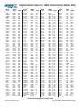
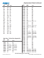
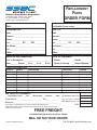
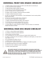
1
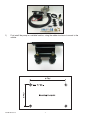
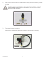
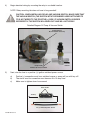
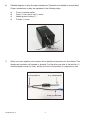
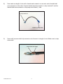
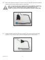
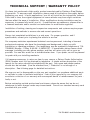
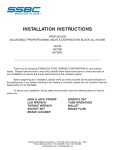
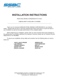
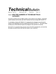
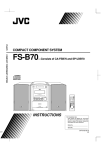
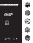
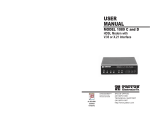
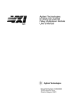
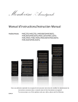
INSTALLATION INSTRUCTIONS
Electric Vacuum Pump Kit 28146
_____________________________________________________________________
Thank you for choosing STAINLESS STEEL BRAKES CORPORATION for your braking
needs. Pleases take the time to read and carefully follow these instructions to insure the ease of
your installation as well as the proper performance of the complete system.
Before beginning your installation, please verify you have received all the parts indicated on
the packing slip. If you believe anything to be missing or incorrect, please call our Customer Service
Department at 716-759-8666.
PRODUCT WARRANTY
This product carries a limited one (1) year warranty against manufacture defects. Failure to properly
install or use the product as intended, or modifying the product and/or components of the kit, will
void the manufacturer’s warranty.
Stainless Steel Brakes Corporation has a complete inventory of replacement parts and rebuild kits
for the electric pump. Contact our customer service department for any assistance you might need.
Stainless Steel Brakes Corporation • 11470 Main Road • Clarence, NY 14031
Phone: (800) 448-7722 • (716) 759-8666 • Fax: (716) 759-8688
www.ssbrakes.com • [email protected]
1)
First install the pump in a suitable location, using the rubber insulators to mount to the
vehicle.
28146 Revision 5
1
2)
Next, mount the vacuum switch in a suitable location, making sure that the switch is grounded
to vehicle.
IF SWITCH BODY IS NOT PROPERLY GROUNDED, THE ELECTRICAL CIRCUIT
WILL NOT WORK PROPERLY!
3)
Run vacuum hoses as shown below.
NOTE: Switch is unidirectional. (Switch will still function if vacuum lines are reversed.)
To brake booster
28146 Revision 5
2
4)
Begin electrical wiring by mounting the relay in a suitable location.
NOTE: Relay mounting tab does not have to be grounded!
CAUTION: WHEN INSTALLING RELAY AND VACUUM SWITCH, MAKE SURE THAT
THE VACUUM SWITCH (THE SWITCH WITH THE RUBBER HOSES ATTACHED TO
IT) IS NOT WIRED TO THE POSITIVE (+) SIDE. IF VACUUM SWITCH IS WIRED
INCORRECTLY, THE SWITCH WILL BURN OUT AND WILL NOT WORK!
Detailed Diagram Of Pump & Vacuum Switch
Pump Exhaust
No connection necessary
Pump Intake
Connect to vacuum switch
5)
To brake
booster
Next, wire the fuse to a positive (+) ignition switched power source.
a)
b)
c)
Positive (+) connection must be a switched source or pump will run with key off!
The circuit used for connection must have an 8 to 10 amp fuse!
Make sure to tighten down fuse screws!
Fuse screws
To relay
To (+) switched power source
28146 Revision 5
3
6)
Detailed diagram of relay & proper connections: (Terminals are labeled on actual relay!)
Proper connections to relay are explained in the following steps.
a)
b)
c)
d)
To top of vacuum switch
From (+) fuse, and to red (+) motor
Vehicle ground, battery (-)
To black (-) motor
c
a
d
b
7)
Splice two wires together, and connect with a female end connector as show below. The
female end connector will connect to terminal 2 on the relay, one wire to the positive (+)
switched power source (to fuse), and the last wire to the positive (+) pump motor side.
To (+) switched power
To relay terminal 2
To red (+) pump motor
28146 Revision 5
4
8)
Now make one length of wire with a female end connector on one end, and a female bullet
nose connector on the other. Connect female terminal connector to relay terminal 5, and the
female bullet nose connector to the pump motor black (-) side.
To relay terminal 5
To black (-) pump motor
9)
Now install vacuum switch clip connector onto the end of a length of wire. Make sure to crimp
down ends!
Crimp down ends tightly
28146 Revision 5
5
10)
Next, install a female end connector to the end of the wire, and insert the vacuum switch clip
connector into the vacuum switch connector as show below.
NOTE: CONNECTOR PIN ONLY INSERTS INTO VACUUM SWITCH CONNECTOR
ONE WAY! DO NOT FORCE PIN INTO BODY! MAKE SURE THAT THE
CONNECTOR LINES UP WITH PIN ON VACUUM SWITCH WHEN CONNECTING!
Insert into switch connector
11)
Finished assembly should look like the picture below. Now connect black vacuum switch
connector to top of vacuum switch, and connect female terminal to relay terminal 1.
Connect to
vacuum switch
Connect to relay terminal 1
28146 Revision 5
6
12)
Lastly, make one wire as shown in the picture below. One end will have a female end
connector connected to relay terminal 3, and the other end will have a ring terminal that will
attach to a good ground point on the vehicle.
Connect to
relay terminal 3
Connect to vehicle ground (-)
13)
Congratulations, you have completed installation of the vacuum pump! Before you start the
vehicle, review the simplified wiring diagram pictures below to make sure all of your
connections are correct:
Relay terminal 1
Relay terminal 2
(+) 12 volt
To vacuum switch
To (+) pump (red)
Relay terminal 3
Relay terminal 5
To ground (-)
28146 Revision 5
To (-) pump (black)
7
POSSIBLE ELECTRICAL PROBLEMS
FAULT
POSSIBLE CAUSE
SOLUTION
Pump doesn’t work
Blown fuse
Switch not grounded
Vacuum switch connector not connected
Replace fuse
Check wiring & ground
Check top of vacuum switch
Vacuum pump won’t stop
Vacuum switch failure
Relay failure
Replace vacuum switch
Replace relay
28146 Revision 5
8
Solutions Guide
to commonly asked questions.
Why is my brake pedal soft?
How do you bench bleed a Master
Cylinder?
1) In most cases, Air is trapped in the lines or calipers.
Try re-bleeding the system. Do not force new fluid into
new brake lines. It may foam and be very difficult to
bleed. Make sure that the bleeder screws on the
calipers are facing upward!
Secure one of the ears in a vise so that you can take a
large screwdriver and push the piston in. Fill the
reservoir with clean fluid. Take a dummy line or our M/C
bleeding kit and hook it up to the two ports. Front line to
front and rear line to rear reservoirs. Slowly stroke the
master and let it return slowly. You should see many air
bubbles in the fluid. Repeat this step until you do not
see any more air bubbles. SSBC recommends ten (10)
slow pumping strokes after you see no more air
bubbles. This will insure a good hard pedal. (See SSBC
part #0460 Instruction Sheet)
2) If all the air is out of the system, the pushrod from
the booster may need adjustment, under the dash, to
make it longer. Do not extend it too long or it will not
allow the fluid to return, causing brakes to drag. Your
pushrod may not be adjustable. If the pushrod can be
made longer, try ¼ turn adjustments at a time. SSBC
stocks adjustable pushrods for many vehicles. In
addition, the pushrod between the Booster and the
Master Cylinder may need adjustment. Not all Booster
to Master pushrods are adjustable.
What is the best pad for my vehicle?
Your choice of pads should be determined by how and
where you drive the vehicle. If you drive in heavy stop
and go traffic you would need a different pad than
someone who is road racing. Contact SSBC for the
correct application.
3) You may have a bad Master Cylinder. Before you
determine this, you should make sure that all the air is
out of the system. When installing a new Master
Cylinder, always bench bleed first. If you did not, take
off the Master Cylinder and bench bleed it. (See Bench
Bleeding Instructions below)
How often should brake fluid be
changed? (street application only,
not racing)
Why does the car pull to one side?
The side that the car is pulling to is the caliper that is
working. Re-bleed the opposite side and try carefully
stopping again.
When brake fluid turns brown, it is time to change the
fluid. The brown color indicates that the fluid has
absorbed water and dirt. D.O.T. #3 & #4 fluids absorb
water. Silicone brake fluid is not for track racing.
Why does it feel like there is no
Power Assist?
How can I tell which reservoir is the
front or rear of the Master Cylinder?
The Booster may not be getting enough vacuum to
operate. On some high lift cams, the engine does not
develop enough vacuum. The Booster needs at least
16” of vacuum to operate correctly at idle. If you do not
have at least 16 inches of vacuum at idle, you may have
to add a vacuum pump to your system.
Check for vacuum leaks. There may be leaks in the
intake manifold or hoses that would cause low vacuum.
The Booster may be bad. Do a vacuum test. If the
Booster can retain a vacuum for three (3) minutes after
the vehicle is shut off, it is not a bad Booster (refer to
steps 1 & 2). All Master Cylinders must be bench bled
in a vise before being installed on the vehicle.
Solutions Guide Revision 5
The front reservoir is usually larger than the rear. In
some cases, they are the same size. As a rule, for GM
cars & trucks, the rear reservoir is for the rear brakes.
On Ford cars & trucks, the front reservoir is for the rear
brakes. On front wheel drive vehicles, the brakes are
split diagonally. Each bowl of the master cylinder
services one front wheel and one rear wheel. This will
be important if you are installing a distribution block,
proportioning valve, or residual valve. Hint: The larger
bowl will feed the disc brakes.
1
716-759-8666 • [email protected]
Where is the best place to install a
proportioning valve?
How much brake pressure does it
take to stop my vehicle?
The best place to install a proportioning valve is after
the distribution block. Do Not install it between the
Distribution Bock and the Master Cylinder. You will
not be able to get a hard pedal. Anywhere after the
Distribution Block and before the rear flex hose is
acceptable for installation.
Most vehicles, power or non power brake, develop
1,200 P.S.I. When you panic stop or jump on the brakes
hard, a surge of 1,400 P.S.I. can be achieved. If a
factory proportioning valve installed on the vehicle, the
rear brakes are only developing 600 – 700 P.S.I. Drum
brakes require lower pressure because they grab more
quickly. When rear disc brakes are installed, the rear
brake pressure may be increased to 800 – 1,000 P.S.I.
or more. A good way to check the pressures and to see
if the system is working correctly, use a pressure gauge
screwed into the bleeder port (SSBC part # A1704). A
vehicle with less than 600 P.S.I will not stop!
Why should the flex hoses be
replaced? They look O.K. from the
outside.
Flex hoses should be replaced every time the calipers
are serviced. They flex up and down, just like a shock
absorber. They are also under high pressure internally.
Flex hoses have a rubber liner that will collapse over
time. If it does collapse, it will act as a check valve and
not allow fluid to return to the Master Cylinder.
How tight should the wheel bearings
be?
The front bearings should always be torqued. Not just
hand tightened. Bearings usually require 12-15 Ft./Lbs.
of torque. Then you will probably need to back off a little
to align the cotter pin hole. Do Not over tighten; the
bearing life will be shortened. This procedure only
applies to rear wheel drive vehicles with separate
bearings and races. On vehicles with one piece sealed
bearing assemblies or hub assemblies, refer to a
service manual.
Will my pedal get harder by replacing
the flex hoses?
No. When the flex hoses are replaced, re-bleed the
brake system. Normally what happens is that bleeding
causes a harder brake pedal. A better bleeding job and
taking your time will result in the same situation.
What type of differential fluid should
I use in my rear axle?
Are the rubber flex hoses expanding
causing a soft pedal?
If you have positraction, use a Hypoid or Limited Slip
additive that is designed for your particular rear end. If
you do not have positraction, any type of 80 –90 weight
gear lube is acceptable. Fluid should be changed often
if you are trailering or any type of extreme usage. This
fluid does brake down with time and usage.
Not likely. A soft pedal is usually a sign of air in the
system due to poor bleeding. Flex hoses have nylon
webbing that is molded into the internal rubber. It is very
strong and will hold up to 3,000 P.S.I. Installing braided
stainless steel hoses is not necessary; it only improves
appearance.
Solutions Guide Revision 5
2
716-759-8666 • [email protected]
Replacement Pads for SSBC Performance Brake Kits
SSBC
Kit #
SSBC
Pad #
FMSI #
SSBC
Kit #
SSBC
Pad #
FMSI #
SSBC
Kit #
SSBC
Pad #
FMSI #
SSBC
Kit #
SSBC
Pad #
FMSI #
A109
A109-1
A109AF
A109AR
A109S
A110
A110-10
A110-11
A110-12
A110-13
A110-14
A110-15
A110-16
A110-17
A110-18
A110-19
A110-2
A110-3
A110-4
A110-5
A110-6
A110-7
A110-8
A110-9
A111
A111-10
A111-11
A111-12
A111-13
A111-14
A111-15
A111-16
A111-17
A111-18
A111-19
A111-2
A111-20
A111-21
A111-22
A111-23
A111-24
A111-25
A111-26
A111-27
A111-28
A111-29
A111-3
A111-30
A111-31
A111-32
A111-33
A111-4
A111-5
A111-6
A111-7
A111-8
A111-9
A112
A112-1
A112-11
A112-12
A112-13
A112-14
A112-15
A112-16
A112-17
1012
10108
10128
10128
1012
1049
10129
10113
10113
1015
10135
1095
10128
10128
1047
10113
1047
10128
10128
1015
1015
10110
10110
10129
1049
1015
1015
10110
10110
10110
10110
10129
10129
10129
10129
1047
10113
10113
10113
10113
1015
10135
1095
10128
1015
10129
10135
1095
10128
10128
10128
10128
10128
10128
10128
A1015-3
1015
1047
1047
1095
1095
10113
1047
1047
1095
10133-1
D-8
D-531
D-531
D-531
D-8
D-204
D-43
D-154
D-154
D-52
D-137
D-731
D-531
D-531
D-347
D-154
D-347
D-531
D-531
D-52
D-52
D-11
D-11
D-43
D-204
D-52
D-52
D-11
D-11
D-11
D-11
D-43
D-43
D-43
D-43
D-347
D-154
D-154
D-154
D-154
D-52
D-137
D-731
D-531
D-52
D-43
D-137
D-731
D-531
D-531
D-531
D-531
D-531
D-531
D-531
*
D-52
D-347
D-347
D-731
D-731
D-154
D-347
D-347
D-731
D-784
A112-2
A112-3
A112-4
A112-5
A112-6
A112-7
A112-8
A112-9
A112-93
A113
A113-1
A113-10
A113-11
A113-12
A113-4
A113-5
A113-6
A113-7
A113-8
A113-9
A114
A115
A116
A117
A117-1
A117-10
A117-11
A117-12
A117-13
A117-14
A117-15
A117-2
A117-3
A117-4
A117-5
A117-6
A117-7
A117-8
A117-9
A118
A120
A120-10
A120-11
A120-12
A120-2
A120-2P
A120-2PO
A120-2PPO
A120-3
A120-4
A120-5
A120-6
A120-7
A120-7A
A120-7M
A120-8
A120-9
A120D
A120P
A121
A121-2P
A121-2PA
A121-2PAPO
A121-2PM
A121-2PMPO
A121P
1047
1071
1047
1061-1
10128
1071
10128
1015
1047
1071
1071
1071
1015
1095
10128
1015
10128
10128
1070
10128
1047
1047
1049
1047
1047
10113
1095
1095
10113
10113
10113
1047
1071
1071
10128
10128
10128
1047
1095
1049
A1033
10128
10128
10128
10110
10110
10129
10129
10128
10144
10144
10128
10128
10128
10128
10128
10128
A1033
A1033
A1033
10110
10110
10110
10110
A10129
A1033
D-347
D-412
D-347
D199
D-531
D-412
D-531
D-52
D-347
D-412
D-412
D-412
D-52
D-731
D-531
D-52
D-531
D-531
D-413
D-531
D-347
D-347
D-204
D-347
D-347
D-154
D-731
D-731
D-154
D-154
D-154
D-347
D-412
D-412
D-531
D-531
D-531
D-347
D-731
D-204
*
D-531
D-531
D-531
D-11
D-11
D-43
D-43
D-531
D-289
D-289
D-531
D-531
D-531
D-531
D-531
D-531
*
*
*
D-11
D-11
D-11
D-11
*
*
A121P-A
A121P-M
A123
A123-1
A123-13
A123-14
A123-15
A123-16
A123-17
A123-18
A123-1A
A123-1C
A123-2
A123-3
A123-3A
A123-4
A123-4A
A123-5
A123-58
A123-58A
A123-59
A123-59A
A123-5A
A123-6
A123-67
A123-68
A123-69
A123-6A
A123-7
A123-8
A123-9
A123-A
A124
A125
A125-1
A125-10
A125-11
A125-12
A125-13
A125-14
A125-15
A125-16
A125-17
A125-18
A125-19
A125-1F
A125-2
A125-20
A125-21
A125-22
A125-23
A125-24
A125-25
A125-26
A125-27
A125-28
A125-29
A125-3
A125-30
A125-31
A125-32
A125-33
A125-34
A125-35
A125-36
A125-4
A1033
A1033
1050
1050
1095
1095
10116
10116
1095
1095
1015
1050
1071
1050
1015
1050
1015
1050
1050
1015
1050
1015
1015
1071
1071
1071
1071
1071
10128
10128
10128
1015
1047
1047
1047
10128
10128
10128
10128
1015
1015
1015
1015
10110
10110
1047
1047
10110
10128
10129
10129
10129
10129
10113
10113
10113
10113
1047
10113
1015
1015
10135
1095
10128
10128
1047
*
*
D-52
D-52
D-731
D-731
D-749
D-749
D-731
D-731
D-52
D-52
D-412
D-52
D-52
D-52
D-52
D-52
D-52
D-52
D-52
D-52
D-52
D-412
D-412
D-412
D-412
D-412
D-531
D-531
D-531
D-52
D-347
D-347
D-347
D-531
D-531
D-531
D-531
D-52
D-52
D-52
D-52
D-11
D-11
D-347
D-347
D-11
D-531
D-43
D-43
D-43
D-43
D-154
D-154
D-154
D-154
D-347
D-154
D-52
D-52
D-137
D-731
D-531
D-531
D-347
A125-5
A125-6
A125-7
A125-8
A125-9
A125-F
A125P
A126
A126-1
A126-10
A126-11
A126-12
A126-13
A126-14
A126-15
A126-16
A126-17
A126-18
A126-19
A126-2
A126-20
A126-21
A126-22
A126-23
A126-24
A126-25
A126-26
A126-27
A126-28
A126-29
A126-3
A126-30
A126-31
A126-32
A126-33
A126-34
A126-35
A126-37
A126-38
A126-39
A126-4
A126-40
A126-41
A126-46
A126-5
A126-51
A126-6
A126-61
A126-7
A126-71
A126-71A
A126-7A
A126-8
A126-9
A127
A127-1
A127-2
A127-3
A127-4
A127-5
A127-6
A127-7
A127-8
A127-9
A128
A128-1
1047
1047
1047
10128
10128
1047
1047
1070P
1047
1015
1015
1015
1094A
1094A
1094A
1094A
1094A
1015
1094A
1047
1015
10129
10128
10128
10128
10128
10128
10128
10128
10128
A1094B
10128
10128
1015
10128
10128
10128
1095
1095
1095
A1094B
10126
10126
10126
1047
1047
1050
1050
1094
1094
A1094
A1094
1094
1049
1047
10128
1070
1071
10128
10128
1015
1047
1015
1047
1047
1047
D-347
D-347
D-347
D-531
D-531
D-347
D-347
D-413
D-347
D-52
D-52
D-52
D-370
D-370
D-370
D-370
D-370
D-52
D-370
D-347
D-52
D-43
D-531
D-531
D-531
D-531
D-531
D-531
D-531
D-531
*
D-531
D-531
D-52
D-531
D-531
D-531
D-731
D-731
D-731
*
D-834
D-834
D-834
D-347
D-347
D-52
D-52
D-369
D-369
*
*
D-369
D-204
D-347
D-531
D-413
D-412
D-531
D-531
D-52
D-347
D-52
D-347
D-347
D-347
*RE-ORDER PADS DIRECTLY FROM SSBC
Solutions Guide Revision 5
3
716-759-8666 • [email protected]
...Replacement Pads Continued
SSBC
Kit #
SSBC
Pad #
FMSI #
SSBC
Kit #
SSBC
Pad #
FMSI #
SSBC
Kit #
SSBC
Pad #
FMSI #
SSBC
Kit #
SSBC
Pad #
FMSI #
A128-2
A128-3
A128-4
A128-5
A128-6
A128-7
A129
A129-1
A129-10
A129-12
A129-13
A129-1A
A129-2
A129-20
A129-22
A129-23
A129-24
A129-2A
A129-3
A129-3A
A129-4
A129-4A
A129-5
A129-6
A129-8
A129-A
A130
A130-1
A130-2
A132
A132-1
A132-A
A132-M
A133
A133-1
A133-2
A133-2P
A133-3
A133-3P
A133-3PO
A134
A134-1
A134-1P
A134-1PPO
A135
A135-1
A135-1A
A135-2
A135-3
A136
A136-1
A137
A137-1
A137-1A
A137-2
A137-3
A137-3A
A138
A138-1
A138-1A
A138-2
A138-3
A138-4
A138-A
A140
A140-1
1047
1049
1047
1049
1047
1047
1050
1050
10128
1050
1050
1015
1050
10128
1095
10128
1095
1015
1050
1015
1050
1015
1071
10128
10128
1015
1047
1047
1047
1046
1046
1046
1046
1046
1046
A1033
A1033
10110
10110
10129
1046
1046
10110
10110
1050
1094A
A1094
1094
10110
1047
1047
1012
1050
1015
10128
1050
1015
1084-2
1084-2
10113
1050
1050
1050
10113
1084-2
10128
D-347
D-204
D-347
D-204
D-347
D-347
D-52
D-52
D-531
D-52
D-52
D-52
D-52
D-531
D-731
D-531
D-731
D-52
D-52
D-52
D-52
D-52
D-412
D-531
D-531
D-52
D-347
D-347
D-347
D-34
D-34
D-34
D-34
D-34
D-34
*
*
D-11
D-11
D-43
D-34
D-34
D-11
D-11
D-52
D-370
*
D-369
D-11
D-347
D-347
D-8
D-52
D-52
D-531
D-52
D-52
D-154
D-154
D-154
D-52
D-52
D-52
D-154
D-154
D-531
A141
A141-1
A142
A142-1
A143
A143-1
A143-5
A143-58
A143-59
A144
A144-1
A145
A145-1
A146
A146-1
A148
A148-1
A148-14
A148-14A
A148-15
A148-15A
A148-16
A148-16A
A148-17
A148-17A
A148-18
A148-18A
A148-1A
A148-2
A148-22
A148-23
A148-23FS
A148-23FSE
A148-23RS
A148-23RSE
A148-24FSE
A148-24RS
A148-24RSE
A148-25FSE
A148-25RSE
A148-26
A148-26FS
A148-26RS
A148-27
A148-27FS
A148-27RS
A148-28
A148-29
A148-3
A148-30
A148-30E
A148-31
A148-31A
A148-32
A148-32A
A148-33
A148-34
A148-4
A148-4E
A148-5
A148-6F
A148-6FE
A148-6G
A148-6GE
A148-7F
A148-7FE
1084-2
1071
1050
1071
1084-2
1071
1084
1084
1084
1084-2
1071
1084-2
1071
1071
1084-2
1084-2
1084-2
1050
1015
1050
1015
1050
1015
1050
1015
1050
1015
10113
A1033
1050
10110
10110
10129
10110
10129
10129
10110
10129
10129
10129
10128
10128
10128
10128
10128
10128
10128
10128
A1033
10110
10129
1084-2
10113
1084-2
10113
1095
1095
10110
10129
10110
A1033
10129
A1033
10129
10110
10129
D-154
D-412
D-52
D-412
D-154
D-412
D-154
D-154
D-154
D-154
D-412
D-154
D-412
D-412
D-154
D-154
D-154
D-52
D-52
D-52
D-52
D-52
D-52
D-52
D-52
D-52
D-52
D-154
*
D-52
D-11
D-11
D-43
D-11
D-43
D-43
D-11
D-43
D-43
D-43
D-531
D-531
D-531
D-531
D-531
D-531
D-531
D-531
*
D-11
D-43
D-154
D-154
D-154
D-154
D-731
D-731
D-11
D-43
D-11
*
D-43
*
D-43
D-11
D-43
A148-7G
A148-7GE
A148-A
A150
A150-1
A150-2
A151
A151-1
A151-2
A152
A152-1
A153
A153-1
A153-2
A153-3
A154
A154-1
A154-2
A154-3
A154-4
A154-5
A154-6
A155
A155-1
A155-2
A156
A156-1
A156-2
A156-3
A156-4
A157
A157-1
A157-2
A158
A158-1
A158-2
A158-3
A158-4
A159
A159-1
A160
A160-1
A160-2
A160-3
A160-4
A161
A161-1
A161-2
A162
A162-1
A162-2
A162-3
A163
A163-1
A163-2
A163-3
A163-4
A163-5
A163-6
A163-7
A163-8
A163-9
A164
A164-1
A164-10
A164-11
10110
10129
10113
1047
1047
1047
1071
10113
1095
A1033
10110
A1033
A1033
10110
10110
A1033
A1033
10110
10110
A1033
A1033
1095
1047
1047
1047
A1033
A1033
10110
10110
1095
1047
10128
10128
1047
1047
1094A
1094A
10128
10100
1094A
10128
1047
1015
1015
1047
1015
1047
1015
1095
10113
1095
10113
1015
1047
1015
1015
1047
1015
10113
10113
10113
10113
10128
10128
10128
10128
D-11
D-43
D-154
D-347
D-347
D-347
D-412
D-154
D-731
*
D-11
*
*
D-11
D-11
*
*
D-11
D-11
*
*
D-731
D-347
D-347
D-347
*
*
D-11
D-11
D-731
D-347
D-531
D-531
D-347
D-347
D-370
D-370
D-531
D-268
D-370
D-531
D-347
D-52
D-52
D-347
D-52
D-347
D-52
D-731
D-154
D-731
D-154
D-52
D-347
D-52
D-52
D-347
D-52
D-154
D-154
D-154
D-154
D-531
D-531
D-531
D-531
A164-12
A164-13
A164-14
A164-15
A164-16
A164-17
A164-2
A164-3
A164-4
A164-5
A164-6
A164-7
A164-8
A164-9
A165
A165-1
A165-2
A165-3
A165-4
A166-1
A166-10
A166-13
A166-14
A166-15
A166-16
A166-17
A166-18
A166-19
A166-1A
A166-2
A166-20
A166-21
A166-22
A166-23
A166-24
A166-25
A166-26
A166-27
A166-28
A166-29
A166-3
A166-30
A166-3A
A166-4
A166-5
A166-6
A166-7
A166-8
A166-9
A167
A167-1
A167-2
A167-3
A167-4
A167-5
A168
A168-1
A168-10
A168-11
A168-2
A168-3
A168-4
A168-5
A168-6
A168-7
A168-8
10128
10129
10128
10126
10128
10126
10128
10128
10128
10128
10128
10128
10128
10128
10128
10128
1095
1095
10133-1
1015
1015
1015
1015
10128
1015
1015
10128
1015
1015
10128
1015
10108
1047
A1015-3
1015
1047
1047
1047
1047
1047
1015
1047
1015
10128
1015
1015
1015
1015
10128
1015
1015
10128
1015
1015
10128
1015
1015
1015
1015
10128
1015
1015
10128
1015
1015
10128
D-531
D-43
D-531
D-834
D-531
D-834
D-531
D-531
D-531
D-531
D-531
D-531
D-531
D-531
D-531
D-531
D-731
D-731
D-784
D-52
D-52
D-52
D-52
D-531
D-52
D-52
D-531
D-52
D-52
D-531
D-52
D-531
D-347
*
D-52
D-347
D-347
D-347
D-347
D-347
D-52
D-347
D-52
D-531
D-52
D-52
D-52
D-52
D-531
D-52
D-52
D-531
D-52
D-52
D-531
D-52
D-52
D-52
D-52
D-531
D-52
D-52
D-531
D-52
D-52
D-531
*RE-ORDER PADS DIRECTLY FROM SSBC
Solutions Guide Revision 5
4
716-759-8666 • [email protected]
...Replacement Pads Continued
SSBC
Kit #
SSBC
Pad #
FMSI #
A170
A170-1
A171
A171-1
A171-2
A171-3
A172
A172-1
A172-2
A172-3
A172-4
A172-5
A172-6
A173
A173-1
A173-3
A174
A174-1
A180-M
A180-S
A181
A182
A185-M
A185-S
A186-1
A187
A187-1
A187-2
A187-3
A187-4
A188
A188-1
A189
A189-1
A190
A191
A192
A193
A193-1
A194
1015
10128
1015
1015
10128
1047
1015
1015
1047
1015
1015
1015
1015
10128
10128
A10135
1015
1015
1015
1015
10113
10113
1015
1015
A1094
1095
1095
10126
10126
10133-1
10110
10110
10110
1095
A10129
10129
10135
1095
10133-1
1097
D-52
D-531
D-52
D-52
D-531
D-347
D-52
D-52
D-347
D-52
D-52
D-52
D-52
D-531
D-531
*
D-52
D-52
D-52
D-52
D-154
D-154
D-52
D-52
*
D-731
D-731
D-834
D-834
D-784
D-11
D-11
D-11
D-731
*
D-43
D-137
D-731
D-784
D-614
Short Stop...™ Slotted Rotor Upgrade Kits
SSBC
Kit #
SSBC
Pad #
FMSI #
A2350000
A2350001
A2350002
A2350003
A2350004
A2350004R
A2350005
A2350006
A2350007
A2350008
A2350008R
A2350009
A2350009R
A2350010
A2350012
A2350013
10112
1015
1015
10113
1099(F) 1070(R)
1070
10101(F) 10102(R)
1081(F) 1070(R)
1081(F) 1070(R)
1095(F) 1096(R)
1096
1097(F) 1098(R)
1097(F) 1098(R)
1015
1015
1081
D-8
D-52
D-52
D-154
D-623(F) D-413(R)
D-413
D-294(F) D-295(R)
D-412 (F) D-413(R)
D-412 (F) D-413(R)
D-731(F) D-732(R)
D-732
D-614(F) D-628(R)
D-614(F) D-628(R)
D-52
D-52
D-412
SSBC
Kit #
SSBC
Pad #
A2350014
A2350014R
A2351000
A2351001
A2351002
A2351003
A2351004
A2351005
A2351006
A2351007
A2351008
A2351009
A2351010
A2351011
A2351012
A2351013
A2351014
A2351015
A2351016
A2351017
A2351018
A2351019
A2351020
A2351021
A2351022
A2351023
A2351024
A2351025
A2351026
A2351027
A2351028
A2360000
A2360001
A2360002
A2360003
A2360004
A2360005
A2360006
A2360007
A2360008
A2360009
A2360010
A2360011
A2361001
A2361002
A2361003
A2370000
A2370001
A2370002
A2370003
A2370004
A2370005
A2370006
A2370007
A2370008
A2370009
A2370010
A2370011
A2370012
A2370013
A2370014
A2370015
A2370016
A2370017
A2380001
A2380002
10116
D-749
10117
D-750
1015
D-52
1015
D-52
1015
D-52
10100
D-368
1094
D-369
1094
D-369
1094
D-369
1015
D-52
10100
D-368
1094
D-369
1094
D-369
1015
D-52
1094
D-369
1015
D-52
1094
D-369
1015
D-52
1094
D-369
10113
D-154
10113
D-154
10118(F) 10119(R) D-785(F) D-792(R)
10126
D-834
10119
D-792
10118
D-785
10113
D-154
10133-1
D-784
10118(F) 10143(R) D-785(F) D-974A(R)
10143
D-974A
10133-1(F) 10134(R) D-784(F) D-785(R)
10133-1
D-784
A1033
*
1046
D-34
1046
D-34
1066
D-237
1061(F) 1049(R)
D-199(F) D-204(R)
1061
D-199
10103(F) 10104(R) D-600(F) D-627(R)
1081(F) 10145(R) D-412(F) D-627A(R)
1061-1(F) 1047(R) D-199(F) D-347(R)
10127
D-711
10127
D-711
10137(F) 10104(R) D-491(F) D-627(R)
10146(F) 10147(R) D-749(F) D-1012(R)
10146(F) 10147(R) D-749(F) D-1012(R)
10147
D-1012
1092
D-203
1092
D-203
1093
D-477
1015
D-52
1093
D-477
10111
D-529
1094
D-369
1094
D-369
10111
D-529
10111
D-529
10111
D-529
10114
D-746
10120
D-820
10125
D-702
10125
D-702
1093(F) 10139(R) D-477(F) D-666(R)
10140(F) 10141(R) D-790(F) D-791(R)
10142(F) 10141(R) D-945(F) D-791(R)
10121(F) 10122(R) D-591(F) D-512(R)
10123(F) 10124(R) D-592(F) D-592(R)
FMSI #
*RE-ORDER PADS DIRECTLY FROM SSBC
Solutions Guide Revision 5
5
716-759-8666 • [email protected]
REPLACEMENT
PARTS
ORDER FORM
Stainless Steel Brakes Corporation
11470 Main Road • Clarence, NY 14031
Ph: 716-759-8666 Fx: 716-759-8688
ssbrakes.com • [email protected]
DATE: __________________________
CUSTOMER #
ORDERED BY:
SHIP TO:
NAME: _______________________________
NAME: _______________________________
COMPANY: ____________________________
COMPANY: ____________________________
STREET: ______________________________
STREET: ______________________________
CITY: ___________ ST: ____ ZIP: _________
CITY: ___________ ST: ____ ZIP: _________
DAY PHONE: ___________________________
DAY PHONE: ___________________________
FAX: _________________________________
FAX: _________________________________
E-MAIL: ______________________________
E-MAIL: ______________________________
VEHICLE INFORMATION:
TYPE OF DRIVING:
TYPE
OF
(from receipt): ____________
AUTOMOBILE: _________________________ __ STREET
YEAR ______ ENGINE: __ 4
CYL.
__ 6
CYL.
__ 8
CYL.
__ RACING
__ STREET & SLALOM
ORDER INFORMATION:
QUANTITY
PART #
DESCRIPTION
UNIT PRICE
ORDER
__ VISA
AMOUNT
Total Merchandise
METHOD OF PAYMENT:
__ CHECK/MONEY
__ STREET MODIFIED
__ MASTERCARD __ DISCOVER
__ AMEX
NY Residents Sales Tax
Ins. (add $0.35 per $100.00)
CREDIT CARD #: _____________________________ EXP: _____________
SIGNATURE: ___________________________________________________
UPS Shipping
(please call)
TOTAL
Price subject to change without notice. Not responsible for typographical errors.
NOTE: Name, address & telephone number must be printed on checks. Driver’s License number
required for personal checks.
FREE FREIGHT
IF ORDERED WITHIN 30 DAYS OF INITIAL ORDER
MAIL OR FAX YOUR ORDER!
Solutions Guide Revision 5
6
716-759-8666 • [email protected]
How and why do I bench bleed a master cylinder?
When installing or replacing a master cylinder, it is critical that all
air is removed from the master cylinder. This can easily be done
by bench bleeding the master cylinder prior to installation. Using
the SSBC master cylinder bleeder kit (#0460):
1) Place your master cylinder in a vise by the ears (not body).
Make sure it is level.
2) Attach a piece of clear plastic hose to the short end of one of
the plastic nozzles. Do the same to the other hose and
nozzle.
3) Clip the plastic bridge to the wall and push the ends of the
hose through the holes so they are SUBMERGED in the reservoir on either side of the wall.
4) Press the tapered end of the nozzle FIRMLY into the cylinder port hole with a twisting motion. Repeat this
procedure on the other port hole.
5) Fill the reservoir with CLEAN brake fluid recommended by the manufacturer.
6) Using full strokes, push the piston in, then release. Do this until ALL the air bubbles have disappeared
from the clear plastic hose. (CAUTION-MASTER CYLINDER WILL NOT BLEED PROPERLY UNLESS
HOSES ARE SUBMERGED IN BRAKE FLUID UNTIL THE BLEEDING PROCESS IS COMPLETED.)
Now mount master cylinder and avoid brake fluid leaking out of front and rear ports during installation.
Bleeding steps for Dual Port Master Cylinder
If you have a master cylinder with dual port holes (4 port holes - 2 on each side), it is necessary to bleed both
port sides of the master cylinder. If both sides of the master cylinder are not bled, there will be air trapped in
the master cylinder and your brakes will not function properly.
To bleed dual port master cylinders:
1) Follow steps 1 - 6 above on the side you will be hooking the brake lines to. Plug the other side.
2) Once the air bubbles are no longer visible in the plastic hose, open the bleeder screws in the supplied
plugs and allow the mater cylinder to gravity bleed. DO NOT push the master cylinder piston in while the
plugs are gravity bleeding.
3) When clear, steady streams of fluid are coming out of both bleeders, close and tighten the bleeders. Give
the master cylinder piston several strokes, making sure there are still no bubbles present in the clear
plastic tubes.
4) Remove the tubes and plastic fittings and mount the master cylinder on the vehicle being careful not to
spill brake fluid on any painted surfaces.
Solutions Guide Revision 5
7
716-759-8666 • [email protected]
TORQUE SPECIFICATIONS
BEFORE DRIVING YOUR
VEHICLE, YOU SHOULD
CHECK THE TORQUE ON ALL
NUTS AND BOLTS IN THE KIT,
INCLUDING ANY SLIDER
BOLTS ON THE CALIPERS.
RE-TORQUE CALIPER BOLTS
AFTER 500 MILES. ALL
SPECIFICATIONS ARE IN
FT-LBS.
BOLT GRADES
U.S.
Bolt
Grade
Bolt
Dia.
1/4”
1/4”
5/16”
5/16”
3/8”
3/8”
7/16”
7/16”
1/2”
1/2”
9/16”
9/16”
5/8”
5/8”
3/4”
3/4”
7/8”
7/8”
1”
1”
SAE 7
SAE 8
5.8
8.8
9.8
10.9
Low
Carbon
(soft)
Medium
Carbon
Heat Treat
Medium
Carbon
Alloy
2
5
5
7
7
8
8
Thread Dry
per inch
Oiled
Dry
Oiled
Dry
Oiled
Dry
20
28
18
24
16
24
14
20
13
20
12
18
11
18
10
16
9
14
8
12
4
6
9
12
16
22
24
34
38
52
52
71
98
115
157
180
210
230
320
350
3
4
7
9
12
16
17
26
31
42
42
57
78
93
121
133
160
177
240
265
8
10
17
19
30
35
50
55
75
90
110
120
150
180
260
300
430
470
640
710
6
7
13
14
23
25
35
40
55
65
80
90
110
130
200
220
320
360
480
530
10
12
21
24
40
45
60
70
95
100
135
150
140
210
320
360
520
580
800
860
8
9
16
18
30
35
45
50
70
80
100
110
140
160
240
280
400
440
600
666
12
14
25
29
45
50
70
80
110
120
150
170
220
240
380
420
600
660
900
990
Bolt Dia.
5.8
Oiled
8.8
Oiled
9.8
Oiled
10.9
Oiled
5mm
6mm
8mm
10mm
12mm
3.5
6
15
29
51
5
9
22
44
76
6
10.5
25
51
89
8
12
32
62
111
METRIC
2
SAE 5
Metric
Steel
Type
SAE
SAE 2
Solutions Guide Revision 5
Medium
Carbon Alloy
Oiled
Socket
Head
Cap
Screw
Dry
Socket
Head
Cap
Screw
Oiled
9
10
18
20
35
40
55
60
80
90
110
130
170
180
280
320
460
500
680
740
14
16
29
33
49
54
76
85
113
126
163
181
230
255
400
440
640
700
980
1060
11
13
23
26
39
44
61
68
90
100
130
144
184
204
320
350
510
560
780
845
Per SAE J1701 and SAE J1701M specifications.
8
716-759-8666 • [email protected]
UNIVERSAL FRONT DISC BRAKE CHECKLIST
[
[
[
[
[
[
[
[
]
]
]
]
]
]
]
]
[
[
[
[
[
[
]
]
]
]
]
]
1) Spindle Properly secured to ball joints and tie rods with castle nut and cotter pin.
2) All mounting bolts properly tightened.
3) Wheel bearings properly packed with grease.
4) Inner bearing must be installed before grease seal.
5) Rotor / bearings slide onto spindle with ease.
6) Washer, castle nut properly torqued and cotter pin installed.
7) Calipers installed and properly torqued.
8) Spin rotor and check for any interference. (If any interference is found, resolve problem
before driving vehicle.)
9) Flex lines are properly installed with no interference.
10) Power booster (if applicable) installed properly.
11) Master cylinder bench bled according to the instructions.
12) All brake lines are properly tightened and free of leaks.
13) Turn wheels lock to lock and check for any interference.
14) Place wheel onto vehicle and spin the wheel to make sure there is no interference
between the brakes and wheel.
UNIVERSAL REAR DISC BRAKE CHECKLIST
[
[
[
[
[
]
]
]
]
]
[
[
[
[
[
[
]
]
]
]
]
]
1) All bolts on base bracket properly tightened.
2) All caliper mounting bolts properly tightened.
3) Rotor slides onto axle with ease.
4) No interference with rotor and any other parts (splash shield, brackets, etc.).
5) Caliper is centered over the rotor (because of difference in axle lengths, you may have to
shim caliper in or out).
6) No interference with caliper and rotor.
7) All brake lines are tight with no leaks.
8) Parking brake is properly adjusted and not dragging, with vehicle on ground.
9) Adjustable proportioning valve installed (if applicable).
10) Distribution block modification made (if applicable).
11) Brake system properly bled.
WITH EVERY NEW SET OF ROTORS AND PADS, YOU SHOULD GIVE YOUR
VEHICLE 200 - 250 MILES OF EASY DRIVING TO PROPERLY SEAT THE PADS TO
THE ROTORS. DO NOT TAKE THE VEHICLE UP TO 60 MPH AND JAM ON THE
BRAKES BEFORE THE FIRST 200 - 250 MILE BREAK IN PERIOD IS OVER, OR
YOU WILL GLAZE THE PADS AND ROTORS.
Solutions Guide Revision 5
9
716-759-8666 • [email protected]
TECHNICAL SUPPORT / WARRANTY POLICY
You have just purchased a high quality product manufactured by Stainless Steel Brakes
Corporation. To ensure proper installation, please read all instructions thoroughly before
beginning your work. In most applications, your kit will install as the instructions indicate.
From time to time, the original equipment on some vehicles may have slight variations
that can effect the ease of installation. Minor modifications during installation may be
necessary to successfully install your kit. If modifications are necessary, please refer to
a licensed mechanic and/or contact our technicians for modification approval.
Installation of braking, steering and suspension components and systems require proper
procedures and methods to assure safe and correct operations.
Always test completed installations in a safe area. For proper operation, and if
questionable, correct prior to placing the vehicle in service.
Our company maintains experienced technical service personnel, including a licensed
professional engineer who have the knowledge and background to help you with
installation or operating problems. Our technicians may be reached by telephone at 716759-8666, Monday - Friday, 9:30 AM - 5:30PM EST. If unavailable, please leave a brief
message, including your day phone number, and they will return your call as soon as
possible. You can also e-mail us at [email protected]. If you prefer, we will be pleased
to speak with your installing mechanic.
If it becomes necessary to return an item for any reason, a Return Goods Authorization
(RGA) Number must first be obtained by telephone. A simple written description of the
reason for the return should be included with the part. Your name and phone number
should also be included. (Use the attached form.) “Defective” is not enough of a
description. See following page for detailed instructions.
We urge you not to disassemble or alter any part supplied, nor purchase additional parts
or services in order to facilitate installation. Lack of prior approval by our company will
constitute a violation of our warranty with consequent denial of reimbursement for parts faulty or not.
Before contracting outside professional assistance, please be aware that we do not
reimburse for labor charges under any circumstance. Consult our standard warranty card
provided with your order.
Solutions Guide Revision 5
10
716-759-8666 • [email protected]
NEED TO RETURN A PART?
FOLLOW THESE INSTRUCTIONS.
> Did you call our Technical Assistance (716-759-8666) before you decided to make a
return? If not, you should do so now.
> You must have a Return Goods Authorization Number (RGA) issued to you prior to
returning any item. If you return without an RGA #, you run the risk of not receiving
credit.
> Make sure to include the completed Return Form with invoice and RGA # with your
parts.
> Whenever possible, please return item in original box with invoice and RGA # clearly
marked on the outside of the box.
> Any return must be shipped postage paid - NO collect shipments will be accepted.
> All warranty items will be sent ground UPS. Any other type of shipping service will be
at customer’s expense.
It is a good idea to insure the returned part(s) for the full value to protect yourself against
loss. We strongly suggest you ship by UPS or U.S. Mail, no BUS or AIR shipments will
be accepted. All foreign returns must have authorization.
NOTE:
Under no circumstance should any product(s) or part(s) be returned without
prior authorization number (RGA #). Any part which, in our opinion, shows
evidence of being used, installed contrary to SSBC instruction, defaced,
subjected to improper handling, packaging or shipping by the customer will not
be eligible for exchange, refund or warranty consideration.
Solutions Guide Revision 5
11
716-759-8666 • [email protected]
RETURN FORM
Name: _____________________________
Invoice #: _________________________
Address: ___________________________
Date Purchased: ____________________
___________________________________
Purchased From: ___________________
Phone: ____________________________
List item(s) and a detailed explanation of why you are returning the item(s):
_________________________________________________________________________
_________________________________________________________________________
_________________________________________________________________________
_________________________________________________________________________
_________________________________________________________________________
_________________________________________________________________________
_________________________________________________________________________
_________________________________________________________________________
_________________________________________________________________________
_________________________________________________________________________
RGA # ____________________________
Use this label for your package.
From: ________________________
______________________________
______________________________
TO:
Stainless Steel Brakes Corp.
11470 Main Road
Clarence, NY 14031
RGA #: ______________
Solutions Guide Revision 5
Invoice #: _____________
12
716-759-8666 • [email protected]