1
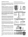
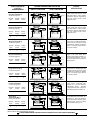
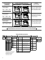
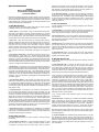
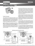
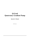
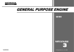
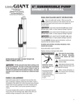
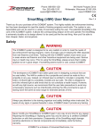
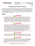
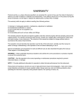
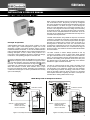
1500 Series
INSTALLATION & SERVICE MANUAL
1500 Induction Control Relays
When a source of alternating current is connected to the primary
coil at terminals 3 and 4, the primary coil sets up a magnetic
flux which circulates through the shortest path following the lines
of least resistance. As shown in Figure 1, this is through the
lower bar of the laminated core on which the secondary coil is
mounted. This magnetic flux induces a voltage in the secondary
or electrode circuit coil. No current can flow in this coil, however,
until the circuit is completed between the electrodes. Thus, the
electrode circuit voltage being generated within the relay has no
connection with the power line.
Principle of Operation
A B/W floatless liquid level control system consists of a relay
of the proper type, a holder designed to support one or more
electrodes or probes in the liquid container, and the corrosion
resistant electrodes themselves. In as much as all B/W induction
relays are quite similar differing only in contact arrangement, the
following description of how a 1500-C Relay functions on a
pump down control application will serve to explain the design,
construction, and operating principles for the entire line.
As shown in diagrams below, the laminated core of the relay is
shaped. The primary coil is assembled to the upper bar of the
core, and the secondary coil for the electrode is placed on the
lower bar. An armature located below the legs of the
core is
connected to an insulated arm carrying the movable contacts.
When the armature is raised, these contacts close or open
the motor and electrode circuits, depending upon whether the
contacts are normally open or closed. (Contacts shown normally
open in this example).
The B/W 1500 induction relay utilizes the liquid as an electrical
conductor to complete the secondary circuit between the upper
and lower electrodes. Thus, when the liquid contacts the upper
electrode, the resulting flow of current in this circuit sets up a
bucking action in the lower bar of the core. This action tends
to divert lines of magnetic force to the core legs and sets up an
attraction that pulls the armature in to contact with the legs, as
shown in Figure 2. This armature movement closes the electrode
and load contacts.
The lower contacts on 1500-C Relays (terminals 9 and 10)
connect the secondary circuit to ground when liquid contacts
the upper electrode and act as a holding circuit to maintain the
relay in its closed position until the liquid falls below the lower
electrode. This holding circuit provides control of the relay over
any desired range in the liquid level, depending on the distance
between the upper and lower electrodes.
The flow of current through the low energy secondary circuit
is very small and varies with the voltage of the secondary coil.
The secondary coil is selected to operate over the resistance
of the liquid being controlled. Accordingly, since there is a wide
range of secondary coils from which to choose, it is important
that complete information regarding the nature of the liquid be
furnished when ordering B/W induction relays.
1500C Relay Used for Pump Down Control
A.C. LINE
A.C. LINE
4
3
FLUX
3
4
5
6
FLUX
5
6
7
8
7
8
9
10
9
10
TO MOTOR STARTER
ARMATURE
ARMATURE
PUMP START
ELECTRODE
GROUND: A GOOD DEPENDABLE
GROUND RETURN
CONNECTION TO THE
LIQUID IS REQUIRED
TO MOTOR STARTER
PUMP STOP
ELECTRODE
PUMP START
ELECTRODE
GROUND: A GOOD DEPENDABLE
GROUND RETURN
CONNECTION TO THE
LIQUID IS REQUIRED
PUMP STOP
ELECTRODE
Figure 1 - Secondary coil circuit open; armature down.
Figure 2 - Secondary coil circuit closed; armature up.
1
Installation Instructions
Relay: Install relay in level upright position. Connect wires
from AC supply to terminals #3 and #4 on relay. Make sure
power is of same rated voltage and frequency as shown
for connection to primary coil on relay data plate. Relays
draw 9 volt amperes.
Field Replaceable and Convertible Contacts
The Series 1500 Induction Relay provides circuit versatility by offering
a contact kit that allows field conversions from N.O. to N.C. or N.C.
to N.O. contact arrangements. This option also allows you to add or
replace contacts (up to 3 per relay) as required for expansion of your
liquid level control needs.
Electrodes: Install electrodes in tank or well by
suspending them vertically from an electrode holder or
some other suspending means. One electrode should be
set at desired start level and one at desired stop level. For
sewage or surface drainage sumps, make sure electrodes
are hung far enough apart so that foreign matter floating
on water cannot foul electrodes. Size 18 or larger Type TW
or THW wire is recommended for connection to the relay.
CAUTION - Although the electrodes are connected
to a low energy secondary coil output which has
inherently low current, there may be up to 800 volts
between the electrodes or from an electrode to
ground. (See Secondary Coil Table.) Thus wiring and
electrodes should be installed to protect personnel
from accidental contact.
Ground: A system ground return circuit is required from the
indicated relay terminal to the liquid in order to complete
the secondary circuit of relay. Conduit should not be
used. Instead, connection should be made directly to
uninsulated metal tank, or to metal pipe connected to tank
below normal low liquid level. In wells, connect ground
to pump or metallic water pipe. For concrete, wood, or
insulated tanks, use an extra common electrode extending
slightly below the longest operating electrode.
Secondary Coil: Because the secondary voltage on all B/
W relays is an induced voltage generated within the relay
itself, the secondary coil should never be connected to any
source of power. Voltage of the secondary coil installed on
a given relay is determined by conductivity of liquid to be
controlled.
Remove cover plate and armature
For a N.O. contact,
install the moveable
contact in the
armature assembly
facing toward the top
of the relay. (away
from the armature)
For a N.C. contact,
install the moveable
contact in the
armature assembly
facing toward
the bottom of the
relay. (toward the
armature).
N.O.
N.O.
N.C.
Contact Kit Part No. 15-000001
N.O. Contact
N.C. Contact
For a N.O. contact, install the
stationary contacts facing toward
the bottom of the relay (toward the
armature).
For a N.C. contact, install the
stationary contacts facing in
toward the top of the relay (away
from the armature).
Load Connections: B/W relays are two-wire control
devices having load contacts rated at 1 hp., single-phase,
115 or 230 volts AC or standard duty pilot rating up to 600
volts AC. In operation, load contacts act as a switch to
open or close a circuit. Connecting them to an external
load does not introduce a source of alternating current into
the circuit.
Accordingly, in making connections for direct operation of
single-phase loads within rated capacity of relay, power
connections must be made as shown in relay wiring
diagram.
To operate higher rated single-phase loads or threephase loads, a magnetic starter must be used. In making
connections to motor starter, follow directions given on
the starter wiring diagram for connecting two-wire control
devices.
2
CONTACT ARRANGEMENT CODE
A
B
1 N.O.
1 N.C.
TOP CONTACT
TERMINALS 1 & 2
C
D
2 N.O.
1 N.O.
1 N.C.
E
F
3 N.O.
2 N.C.
G
H
2 N.O.
1 N.O.
1 N.C.
2 N.C.
J
3 N.C.
R
3
MIDDLE CONTACT
TERMINALS 5 & 6
B/W CONTROLS
LINE VOLTAGE
50/60 Hz
4
6
5
Clawson, Michigan 48017 U.S.A.
7
BOTTOM CONTACT
TERMINALS 9 & 10
2
1
SECONDARY
VOLTS
R
8
1500-
9
10
INDUCTION RELAY
CONTACT
ARRANGEMENT
1500-A Relay
Single Electrode Wiring
Contact Arrangement
WIRING DIAGRAM AND OPERATION
DIRECT OPERATION
1
1
Normally
Closed
0
1500-B Relay
Single Electrode Wiring
Contact Arrangement
Normally
Open
0
Normally
Closed
8
7
10
9
6
ELECTRODE
HOLDER
LINE
VOLTAGE
3
5
SECONDARY
VOLTAGE
9
4
Normally
Open
Normally
Closed
10
9
10
SECONDARY
VOLTAGE
8
7
10
9
9
4
6
SECONDARY
VOLTAGE
TO ISOLATED
LOAD CIRCUIT
8
10
A.C.
LINE
LINE
VOLTAGE
4
SECONDARY
VOLTAGE
8
5
LOAD
ELECTRODE
2
3
6
TO ISOLATED
LOAD CIRCUIT
10
GROUND
GROUND
0
0
LOAD ENERGIZED ABOVE THIS LEVEL
ELECTRODE
3
1
Normally
Closed
Holding
Circuit
1
LINE
VOLTAGE
4
SECONDARY
VOLTAGE
8
5
7
Normally
Open
2
1
A.C.
LINE
6
9
0
1
10
ELECTRODE
1
0
Normally
Closed
2
Holding
Circuit
0
1500-C Relay
Two Electrode Wiring
Contact Arrangement
8
7
10
9
1
Normally
Closed
0
1
7
10
9
0
Normally
Closed
1
3
5
1
4
SECONDARY
VOLTAGE
8
5
LOAD
ELECTRODE
9
SECONDARY
VOLTAGE
6
TO ISOLATED
LOAD CIRCUIT
Pump Down Control for sewage and
sump pumps, condensate return
system, etc. Low Level Cutoff for
submersible pumps.
Normally
closed Solenoid Valve Control for
discharging liquids from tanks, etc.
ELECTRODE
HOLDER
1
A.C.
LINE
LOAD
ELECTRODE
3
2
LINE
VOLTAGE
5
7
10
9
4
6
SECONDARY
VOLTAGE
TO ISOLATED
LOAD CIRCUIT
8
10
Pump Up Control for supply pumps
on elevated tanks and towers, carbonators, etc. High Level Cutoff for
pumps and valves. Normally closed
Solenoid Valve Control for plating
tank and boiler make-up, etc.
GROUND
GROUND
ELECTRODE
HOLDER
LOAD ENERGIZED BELOW THIS LEVEL
ELECTRODE
10
LOAD CIRCUIT CLOSED ABOVE THIS LEVEL
8
LOAD DE-ENERGIZED ABOVE THIS LEVEL
Same as 1500-B Relay above
except that an additional Normally
Closed contact is provided to permit
simultaneous operation of different
types of secondary signal devices
in remote locations.
LOAD CIRCUIT OPEN BELOW THIS LEVEL
4
6
TO ISOLATED
LOAD CIRCUIT
GROUND
2
LINE
VOLTAGE
B
2
LINE
VOLTAGE
ELECTRODE
HOLDER
A.C.
LINE
Holding
Circuit
3
GROUND
7
Normally
Open
8
TO ISOLATED
LOAD CIRCUIT
ELECTRODE
HOLDER
8
1
TO ISOLATED
LOAD CIRCUIT
A
GROUND
SECONDARY
VOLTAGE
LOAD DE-ENERGIZED BELOW THIS LEVEL
1500-D Relay
Two Electrode Wiring
Contact Arrangement
SECONDARY
VOLTAGE
1
LOAD ENERGIZED ABOVE THIS LEVEL
B
ELECTRODE
LOAD CIRCUIT A & B OPEN ABOVE THIS LEVEL
LOAD CIRCUIT A & B CLOSED BELOW THIS LEVEL
A.C.
LINE
6
TO ISOLATED
LOAD CIRCUIT
10
4
9
Holding
Circuit
4
6
LINE
VOLTAGE
5
7
Normally
Open
ELECTRODE
2
3
2
LINE
VOLTAGE
5
LOAD B
ELECTRODE
HOLDER
1
A.C.
LINE
1
3
A.C.
LINE
GROUND
10
A
LOAD CIRCUIT A CLOSED BELOW THIS LEVEL - B OPEN
LOAD A
LOADS A & B DE-ENERGIZED ABOVE THIS LEVEL
LOADS A & B ENERGIZED BELOW THIS LEVEL
6
High or Low Level Signal Control.
High of Low Level Cutoff when
wired in series with Stop button in 3wire pushbutton stations. Can also
be used to interlock various types of
signal devices.
ELECTRODE
HOLDER
SECONDARY
VOLTAGE
9
8
GROUND
4
6
SECONDARY
VOLTAGE
LOAD CIRCUIT A OPEN ABOVE THIS LEVEL - B CLOSED
LINE
VOLTAGE
5
7
Normally
Open
2
4
9
LOAD B
LOAD A ENERGIZED BELOW THIS LEVEL - B DE-ENERGIZED
3
ELECTRODE
2
LINE
VOLTAGE
5
LOAD A
ELECTRODE
HOLDER
GROUND
A.C.
LINE
3
A.C.
LINE
7
LOAD A DE-ENERGIZED ABOVE THIS LEVEL - B ENERGIZED
1500-E Relay
Single Electrode Wiring
Contact Arrangement
LOAD CIRCUIT CLOSED ABOVE THIS LEVEL
LOAD CIRCUIT OPEN BELOW THIS LEVEL
LOAD DE-ENERGIZED BELOW THIS LEVEL
1500-D Relay
Single Electrode Wiring
Contact Arrangement
Same as 1500-A Relay above
except that an additional Normally
Open contact is provided to permit
simultaneous operation of different
types of secondary signal devices
in remote locations.
ELECTRODE
HOLDER
ELECTRODE
HOLDER
2
Low Level Signal Control. High
Level Cutoff when wired in series
with Stop button in 3-wire pushbutton stations. Remote, long distance
and low voltage manual control
applications, etc.
ELECTRODE
HOLDER
1
4
6
2
LINE
VOLTAGE
GROUND
2
High Level Signal Control. Low
Level Cutoff when wired in series
with Stop button in 3-wire pushbutton stations. Remote, long distance
and low voltage manual control
applications, etc.
ELECTRODE
LOAD CIRCUIT OPEN ABOVE THIS LEVEL
LOAD CIRCUIT CLOSED BELOW THIS LEVEL
LINE
VOLTAGE
5
Holding
Circuit
3
7
ELECTRODE
TO ISOLATED
LOAD CIRCUIT
TYPICAL
APPLICATIONS
ELECTRODE
HOLDER
8
1
7
6
5
ELECTRODE
HOLDER
3
8
GROUND
A.C.
LINE
GROUND
A.C.
LINE
SECONDARY
VOLTAGE
LOAD CIRCUIT CLOSED ABOVE THIS LEVEL
LOAD CIRCUIT OPEN BELOW THIS LEVEL
LOAD
LOAD DE-ENERGIZED ABOVE THIS LEVEL
LOAD ENERGIZED BELOW THIS LEVEL
1500-C Relay
Single Electrode Wiring
Contact Arrangement
4
1
6
7
0
ELECTRODE
2
1
2
LINE
VOLTAGE
5
LOAD
GROUND
A.C.
LINE
3
A.C.
LINE
LOAD ENERGIZED ABOVE THIS LEVEL
LOAD DE-ENERGIZED BELOW THIS LEVEL
Holding
Circuit
1
SECONDARY
VOLTAGE
9
Holding
Circuit
0
4
5
7
Normally
Open
1
2
LINE
VOLTAGE
3
A.C.
LINE
PILOT OPERATION
ELECTRODE
ELECTRODE
HOLDER
LOAD CIRCUIT OPEN ABOVE THIS LEVEL
ELECTRODE
LOAD CIRCUIT CLOSED BELOW THIS LEVEL
CAUTION: Electrodes are terminals of live electrical circuits and must be installed to prevent accidental contact by personnel. Control
power must be disconnected before servicing.
A GOOD DEPENDABLE GROUND RETURN CONNECTION TO THE LIQUID IS REQUIRED.
3
INDUCTION RELAY
CONTACT
ARRANGEMENT
WIRING DIAGRAM AND OPERATION
1500-F Relay
Two Electrode Wiring
Contact Arrangement
1
A.C.
LINE
Normally
Closed
2
0
SECONDARY
VOLTAGE
8
7
10
9
9
Holding
Circuit
A.C.
LINE
6
LINE
VOLTAGE
4
SECONDARY
VOLTAGE
8
6
A
TO ISOLATED
LOAD CIRCUIT
B
TO ISOLATED
LOAD CIRCUIT
GROUND
ELECTRODE
HOLDER
ELECTRODE
HOLDER
LOADS A & B ENERGIZED ABOVE THIS LEVEL
1500-G Relay
Two Electrode Wiring
Contact Arrangement
ELECTRODE
2
1
A.C.
LINE
3
1
LOAD B
SECONDARY
VOLTAGE
8
7
10
9
A.C.
LINE
6
ELECTRODE
LOAD CIRCUIT A & B OPEN BELOW THIS LEVEL
4
9
Holding
Circuit
LOAD CIRCUIT A & B CLOSED ABOVE THIS LEVEL
LINE
VOLTAGE
5
7
3
2
LINE
VOLTAGE
4
SECONDARY
VOLTAGE
8
5
LOAD A
6
B
TO ISOLATED
LOAD CIRCUIT
A
TO ISOLATED
LOAD CIRCUIT
1
1
LOAD A DE-ENERGIZED ABOVE THIS LEVEL - B ENERGIZED
GROUND
ELECTRODE
LOADS A ENERGIZED BELOW THIS LEVEL - B DE-ENERGIZED
1500-H Relay
Two Electrode Wiring
Contact Arrangement
3
ELECTRODE
HOLDER
Normally
Closed
1
LOAD A
SECONDARY
VOLTAGE
8
7
10
9
A.C.
LINE
6
ELECTRODE
LOAD CIRCUIT A CLOSED BELOW THIS LEVEL - B OPEN
4
9
Holding
Circuit
LOAD CIRCUIT A OPEN ABOVE THIS LEVEL - B CLOSED
LINE
VOLTAGE
5
7
Normally
Open
2
1
A.C.
LINE
LOAD B
3
2
LINE
VOLTAGE
4
SECONDARY
VOLTAGE
8
5
6
GROUND
A
TO ISOLATED
LOAD CIRCUIT
B
TO ISOLATED
LOAD CIRCUIT
2
1
LOADS A & B DE-ENERGIZED ABOVE THIS LEVEL
Same as 1500-D Relay above
except that additional Normally
Closed contact is provided to permit
simultaneous operation of second
pump. Extra contact can also be
used for signal purposes if desired.
10
GROUND
ELECTRODE
HOLDER
0
Pump Up or Pump Down Control for
same applications listed above for
B/W 1500-C and 1500-D Relays. It
is also suitable for use in controlling
hydropneumatic tanks and motorized valve installations.
10
GROUND
ELECTRODE
HOLDER
1
Same as 1500-C Relay above
except that additional Normally
Open contact is provided to permit
simultaneous operation of second
pump. Extra contact can also be
used for signal purposes if desired.
10
GROUND
1
Normally
Closed
3
5
LOAD B
LOADS A & B DE-ENERGIZED BELOW THIS LEVEL
Normally
Open
2
1
LOAD A
4
5
7
Normally
Open
2
LINE
VOLTAGE
3
TYPICAL
APPLICATIONS
PILOT OPERATION
DIRECT OPERATION
ELECTRODE
LOADS A & B ENERGIZED BELOW THIS LEVEL
ELECTRODE
HOLDER
LOAD CIRCUIT A & B OPEN ABOVE THIS LEVEL
ELECTRODE
LOAD CIRCUIT A & B CLOSE BELOW THIS LEVEL
CAUTION: Electrodes are terminals of live electrical circuits and must be installed
to prevent accidental contact by personnel. Control power must be disconnected before servicing.
A GOOD DEPENDABLE GROUND RETURN CONNECTION TO THE LIQUID IS REQUIRED.
1500
A
Catalog
Section
Catalog Numbering System
S7
L1
Contact
Arrangements
Line Voltage
L1
Normally
Open
Closed
A
1
0
B
0
1
C
2
0
D
1
1
E
0
2
F
3
0
G
2
1
H
1
2
J
0
3
L2
110-120 Volts
50/60 HZ
208-240 Volts
50/60 HZ
Typical Liquids
S1
12 Volts A.C.
Metallic circuits
S2
24 Volts A.C
Metallic circuits
S3
40 Volts A.C.
Acid or caustic solutions: Milk;
Brine and salt solutions; Plating
solutions; Buttermilk; Soups
L3
440-480 Volts
50/60 HZ
L4
550-600 Volts
50/60 HZ
S4
90 Volts A.C
Weak acid or caustic solutions:
Beer; Baby foods; Fruit juices
L5
Dual Voltage
120/240 Volts
50/60 HZ
S7
220 Volts A.C.
Sewage; Most water-except very
soft; Pottery slip; Water soluble oil
solutions; Starch solutions
All contacts rated at:
25 Amp Resistive at 120, 240, or 480 VAC
1 HP Single Phase at 120 or 240 VAC
Heavy Duty Pilot 120 to 600 VAC
2 Amp Resistive at 120 VDC
10 Amp Resistive at 48 VDC
4
Secondary
Coil Voltage
S8
360 Volts A.C.
Very soft water; Sugar syrup
S9
480 Volts A.C.
Steam condensate; Strong alcohol
solutions
S11
800 Volts A.C.
Demineralized or distilled water
X
OC
Enclosure Type
OC
Open Chassis
N1
NEMA 1
General
Purpose
N4
NEMA 4
Weather Proof
N4X NEMA 4X
Corrosion
Resistant
N7
NEMA 7
Classified
Location
N12
NEMA 12
Oil Tight
Additional
Options
X None
M Manual
Push Button
Service Instructions
CAUTION
Be sure to disconnect relay control
power before servicing electrodes
or electrode holders.
B/W relays are designed and built to require a minimum of service in the field.
Each one is tested and adjusted at the factory to insure positive operation and
should not be altered or tampered with prior to installation. If a relay does not
operate properly after it has been installed, the following information will be
helpful in determining the probable cause.
A. Relay Will Not Pull In
If relay will not pull in when liquid contacts upper electrode, failure to operate
is probably caused by one of the following conditions:
1. Power Failure - A power failure to relay can be caused by broken wire,
blown fuse, an open switch, loose screw, corroded connection, etc. Check for
power failure with voltmeter or test light directly on relay line terminals (No.3
and 4 on all B/W relays). Also check voltage at motor starter line terminals
and overload heaters on motor starter to be sure they have not tripped.
2. Open Coils - Coils used in B/W relays very rarely fail unless struck by
lightning or subjected to some severe over-voltage condition. To check coils,
disconnect electrode connections from relay terminals, apply line voltage to
the primary coil, and touch both ends of secondary coil with an insulated
jumper wire. Relay should pull in when the jumper is connected and fall out
when the jumper is removed. Failure to do so indicates that one of the coils is
open. If an open coil is found, contact dealer or the factory for a replacement
relay.
3. Poor Ground Connections - B/W induction relays that operate from a
single electrode i.e., Types 1500-A, C, B, E and D will not function unless
a good dependable ground connection is made to complete the secondary
circuit from one end of the secondary coil through the electrode and liquid,
and back through ground to the other side of the secondary coil. If such a relay
does not operate when liquid contacts the electrode, check ground connection
to be sure it complies with installation instructions.
4. Broken Wires - A broken wire from relay to either electrode will prevent
relay from operating. Broken wires can be checked by shorting the upper and
lower electrode leads together at the electrode holder. If relay fails to pull in,
one or both of the electrode leads is open. The individual leads can then be
checked by running a temporary wire from the relay to holder outside conduit.
If relay pulls in, it may be assumed that break is between the holder and the
electrodes. This can be checked by shorting between the electrode tips with
an insulated jumper.
5. Low Secondary Voltage - If the secondary coil voltage is too low for the
resistance or conductivity of the liquid being controlled, the relay will not pull
in - or it will buzz and chatter before pulling in. In either case, the relay should
be replaced with one which has a higher voltage secondary coil. (See Table.)
If in doubt about proper coil selection, furnish factory with details on liquid - or
send sample for test.
6. Fouled Electrodes - Accumulation of dirt, grease or other deposits on
the upper electrode will insulate it and prevent relay from pulling in. If this
occurs, the electrodes should be inspected and cleaned at regular intervals
as required to eliminate the difficulty. If unusual quantities of oil, grease, or
sludge and encountered, the electrodes can be mounted inside a pipe that is
flushed with clean water. A 4” pipe should be used - with the bottom located
below the lowest water level, and vent holes provided at top so that the level
inside and outside the pipe will be the same. A small flow of water entering the
top of the pipe will cause an outward flow of water from the bottom of the pipe
and prevent undesirable material from entering. Thus, the electrodes have a
clear surface on which to operate and will stay clean.
7. Electrodes Too Short - It is possible for an installation to be completed
in which the upper electrode is suspended at a point where the liquid cannot
make contact. All installations should, of course, be checked to make sure
that proper electrode lengths are provided.
B. Noisy Relay Operation
If the relay functions properly but is noisy in operation, it could be caused by
the following:
1. Poor Electrode Connections - If wire suspended electrodes are used
and have either been lost or not properly connected resultant increase
in resistance is secondary circuit may cause relay to buzz or chatter in
operation. This condition can be corrected by checking to see that proper
electrode connections are made. Excessive accumulation of dirt, grease or
other deposits on the electrodes can also result in noisy relay operation - in
which case periodic cleaning will eliminate the problem.
2. Low Secondary Voltage - If resistance of the liquid being controlled is
at the upper end of the sensitivity range of the relay secondary coil, noisy
operation may result. Sensitivity may be increased slightly by interchanging
the ground and lower electrode connections at the relay. If this does not
correct the condition, the relay should be replaced with one having a higher
voltage secondary coil.
C. One Level Operation
If a relay operates at one level only - starting and stopping at one electrode,
check the following:
1. Electrode Wires - If wires between relay and electrodes are interchanged,
relay will not operate over range in level but from upper electrode only. To
correct, simply reverse connections - either at relay or at electrodes.
2. Ground Connection - Poor ground connection will prevent holding circuit
from functioning and cause relay to operate from the upper electrode only.
This can be easily corrected by making sure that ground connections conform
with Installation Instructions.
3. Holding Circuit - If the holding circuit is not closing, the relay will operate
from the upper electrode only. Since the holding circuit contact carries only
a small current, a slight film of grease or dirt can sometimes prevent proper
closure. To correct, rub contact surface with a clean paper. Do not use sand
paper or emery cloth.
4. Upper Electrode Lead - A ground in lead wire to the upper electrode
will cause relay to operate from lower electrode only. This condition can be
checked out as described below.
D. Relay Will Not Drop Out
If relay will not drop out when liquid falls below lower electrode, check the
following points:
1. Lower Electrode Lead - A ground in the lead wire from relay to lower
electrode will prevent relay from dropping out on low liquid level. If distance
from holder to relay is relatively short, the best way to check for a ground is
to connect a replacement wire from relay to the electrode holder outside the
conduit and test the relay for operation. If it drops out properly it is safe to
assume that a ground exists in the original lower electrode lead wire.
If relay is located a considerable distance from electrode holder, check for
ground as follows: Disconnect power to relay. Remove wires from terminals
in electrode holder and allow them to stick up to eliminate possibility of
contacting a grounded part. Then turn on power to relay. If relay pulls in,
a short is indicated between the electrode leads, from both electrodes to
ground, or secondary coil is shorted internally. If relay does not pull in, short
secondary coil with piece of insulated wire by bridging between relay terminal
connections for upper and lower electrodes. Relay should pull in when this
connection is made and drop out when connection is broken. If relay does not
drop out, a short to ground is indicated in lower electrode lead. This ground
may not be enough to pull in relay, but it can be sufficient to hold relay in once
it has been closed in normal operation.
If any of these conditions exist, disconnect power to relay and replace
grounded wires.
2. Electrode Holder - Excessive dirt or moisture over insulation at electrode
holder or electrodes can cause faulty relay operation. Interior of electrode
holder and its underside should be kept clean and dry. Conduit connections
should be made so that no condensation can enter holder. Underside of
vertically mounted holders should never come in contact with the liquid.
Insulated rod electrodes should be used with horizontally mounted holders.
Electrodes should be kept relatively clean and free of dirt or grease. Check
them periodically to make sure they do not become fouled with floating debris
or insulating deposits.
3. Length of Lead Wires - On installations with excessive distance - over 900
feet - between relay and tank, relay may tend to hold in due to capacitance in
electrode lines and fail to drop out when liquid leaves lower electrode. Since
there are a number of ways to achieve reliable long distance control, complete
information regarding such applications should be submitted to factory for
recommendations.
5
Conductive Liquids
With the exception of products such as oil, gasoline, animal
fats and other similar products, most liquids and some moist
bulk materials have sufficient conductivity to use B/W level
detecting relays. The Series 1500 relay can be used on liquids
with resistance up to about 90,000 ohm-cm (conductivity to 11
micromho/cm).
For liquids with higher resistance the B/W Series 52 relay
described in Catalog Section 5200 must be used for applications
up to 12 megohms resistance. The vapor above some liquids
is considered an explosive hazard and in these cases the B/W
Series 53 relay with FM approved intrinsically safe sensing
circuit should be used. See Catalog Section 5300.
Liquids such as milk and beer, and some pharmaceutical products
will foam during processing. The liquid phase is always a better
conductor than the foam, and when the interface level is to be
detected, the relay sensitivity must be carefully selected and it
would be well to check the factory for our recommendation.
Liquid Description ........................Secondary Coil
Acetic Acid
- Up to 75% ....................................... 90 Volt
- 75 to 90% ........................................ 220 Volt
- Glacial ............................................. Use 5200-H Relay
Acetone .................................................. Use 5200-H, 5300 or 5400 Relay
Acids
- General ........................................... 40 or 90 Volt
- Anhydrous ....................................... Use 5200-H Relay
Alcohols .................................................. Use 5200-H, 5300 or 5400 Relay
Alkalies
- General ........................................... 40 or 90 Volt
- Anhydrous ....................................... Use 5200-H or 5400 Relay
Alum Solutions ....................................... 220 Volt
Aluminum Sulphate ................................ 90 Volt
Aluminum Hydroxide .............................. 90 Volt
Amino Acids ............................................ 90 Volt
Ammonia-Anhydrous Liquid ................... Use 5200-H Relay
Ammonium Chloride ............................... 40 Volt
Ammonium Hydroxide (Ammonia) ......... 220 Volt
Ammonium Nitrate .................................. Use 5300 or 5400 Relay
Ammonium Sulphate .............................. 220 Volt
Baby Foods ............................................ 90 Volt
Barium Chloride ...................................... 40 Volt
Barium Nitrate ........................................ 40 Volt
Beer ...................................................... 90 Volt
Black Liquor ............................................ 40 Volt
Blood ...................................................... 220 Volt
Borax
- Up to 10% ....................................... 220 Volt
- Greater than 10% ............................ 90 Volt
Boric Acid ............................................... 220 Volt
Bread Dough .......................................... 90 Volt
Buttermilk................................................ 24 or 40 Volt
Cadmium Chloride .................................. 40 Volt
Cake Batter ............................................ 220 Volt
Calcium Chloride .................................... 40 Volt
Calcium Hydroxide ................................. 220 Volt
Carbolic Acid
- Up to 90% ....................................... 220 Volt
- 90 to 100% ...................................... Use 5200-H or 5400 Relay
Catsup .................................................... 90 Volt
Caustic Soda (Sodium Hydroxide) ......... 40 Volt
Cement Slurry ........................................ 220 Volt
Chromic Acid .......................................... 40 Volt
Citric Acid................................................ 40 or 90 Volt
Coffee ..................................................... 90 Volt
Condensate
- Ordinary Water ................................ 480 Volt
- D.I. Water ........................................ Use 5200-H Relay
Corn Syrup ............................................. 480 Volt
Corn - Cream Style ................................. 90 Volt
Ethylene Glycol ...................................... Use 5200-H or 5400 Relay
Ferric Chloride ........................................ 90 or 220 Volt
Ferrous Sulphate .................................... 220 Volt
With nearly 50 years of experience B/W has compiled a history
of applications in most major industries around the world. If you
have questions regarding the proper relay selection, write us,
phone us, or send a sample for test. Chances are that we have
the answer for you.
Typical Liquids
The following recommendations are satisfactory for general
use, but because the conductivity of liquids varies greatly with
concentration, purity, temperature and other factors, some
applications may require a different selection. A number of
the products listed are produced as solids such as crystals or
powers, and our relay selection is based on the normally used
commercial solutions of these materials.
Liquid Description ........................Secondary Coil
Formaldehyde ........................................ Use 5200-H Relay
Formic Acid
- Up to 75% ....................................... 90 Volt
- 75 to 90% ........................................ 220 Volt
Glycerine (Glycerol) ................................ Use 5200-H Relay
Hydrochloric Acid .................................... 40 Volt
Hydrofluoric Acid
- Up to 20% ....................................... 220 Volt
- Above 20% ...................................... 40 Volt
Hydrofluorsilicic Acid .............................. 90 Volt
Hydrogen Peroxide ................................. Use 5200-H, 5300 or 5510 Relay
Jams & Jellies ........................................ 360 Volt
Juices - Fruit & Vegetable ...................... 40 or 90 Volt
Lemon Oil Essence ................................ Use 5200-H Relay
Lignite ..................................................... 800 Volt
Lithium Chloride ..................................... 40 Volt
Magnesium Hydroxide ............................ 90 Volt
Mayonnaise ............................................ 220 Volt
Methanol ................................................. Use 5200-H or 5300 Relay
Methyl Ethyl Keystone (MEK) ................. Use 5200-H Relay
Milk ......................................................... 40 Volt
Molasses ................................................ 220 Volt
Muriatic Acid ........................................... 40 Volt
Mustard .................................................. 40 Volt
Nitric Acid................................................ 40 or 90 Volt
Orange Juice .......................................... 90 Volt
Paper Stock ............................................ 220 Volt
Penicillin ................................................. 220 Volt
Phosphoric Acid ...................................... 40 Volt
Plating Solutions ..................................... 40 or 90 Volt
Salts - Chemical ..................................... 40 or 90 Volt
Sodium Carbonate (Soda Ash) ............... 90 Volt
Sodium Chloride (Table Salt) .................. 40 Volt
Sodium Hydroxide (Caustic Soda) ......... 40 Volt
Sodium Hypochlorate ............................. 40 Volt
Sodium Silicate (Water Glass) ................ 90 Volt
Soups ..................................................... 40 Volt
Starch Solutions ..................................... 220 Volt
Sugar
- Low Concentrations ........................ 220 Volt
- High Concentrations ........................ 360 Volt
Sulphuric Acid ......................................... 40 Volt
Vinegar ................................................... 90 Volt
Water
- Sea .................................................. 40 Volt
- Ordinary Potable ............................. 220 Volt
- Ordinary Soft ................................... 360 Volt
- Ordinary Condensate ...................... 480 Volt
- Purified Distilled .............................. 800 Volt or 5200-H Relay
- Purified Deionized ........................... Use 5200-H Relay
Zinc Chloride .......................................... 40 Volt
Copyright 2005 by AMETEK Automation & Process Technologies
1080 N. Crooks Road, Clawson, MI 48017 Toll Free 800-635-0289
Phone 248-435-0700 Fax 248-435-8120 www.AMETEKAPT.com
6
511
1500.M4R
02/05.Z145
10M