1
Saito FG-36 4-Stroke Gasoline Engine
Owner’s Operating Instruction Manual
Model FG-36 | Version 2007
Warning:
•
•
•
•
Do not modify any parts of the engine
This engine is designed for use with radio control model aircraft
In case of modifications by the customer, Horizon Hobby Inc. shall not bear any responsibility from any damage caused by such modification
Keep the ignition system well maintained
SAFETY PRECAUTIONS
VERY
IMPORTANT
Failure to read
and follow these
instructions before
you proceed to
start your engine
may result in
engine damage
and the voiding of
your warranty.
Introduction
Congratulations on purchasing this fine
engine.
It has been over 20 years since Saito
introduced their first 4-stroke glow
engine, the FA-30. Since that time Saito
has led the way in the development of
powerful 4-stroke glow engines, from
the small FA-30 to the large FA-325
5-cylinder radial engine. Leading the
way in innovations, we have seen the
V-twins, and now Saito is proud to
introduce the 4-stroke FG-36
gasoline- powered engine.
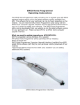
The Saito FG-36 is a 4-stroke gasoline
engine developed exclusively for
model airplanes. It is designed with
an emphasis on high performance,
durability and weight savings. Its
components are modified to adapt to
the gasoline version of the FA-220 glow
engine and are equipped with a 4-stroke
gasoline engine carburetor and ignition
system that matches the FG-36.
Remember, a properly cared for
engine will offer many years of
modeling enjoyment.
1
Features of the FG-36 Gasoline
4-Stroke Engine
• Fuel efficient
• Fuel cost is low
• Aircraft stays relatively clean during operation
Safety Precautions
This manual describes the engine and
its general operating procedures. For
mounting and control, see the instruction manual for the model airplane. Some suggestions are included in this manual for mounting the engine using the included
motor mount.
Note: For proper heat transfer, it is
important to use the Saito motor mount
when mounting this engine in a model
aircraft. The mount facilitates mounting
the engine to the aircraft’s firewall.
• The engine is designed for use on a model radio control airplane. If it is used for any other purpose, we cannot be responsible for its reliability or safety.
• Always use genuine Saito parts
for replacements.
• Be sure to check the propeller before each flight. If it is damaged,replace
the propeller with a new one.
2
E n g ine M ountin g and M uff l er A ttac h ment
• If the propeller hits somethingwhile the engine is in operation, immediately stop the engine and check for damage.
• Start the engine on a flat surface free of stones or other debris.
• When mixing fuel, or operating the engine, do so in a well-ventilated area.
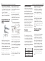
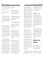
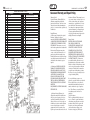
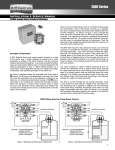
Engine Mounting and
Muffler Attachment
Notes
mount to prevent the bolts from
sinking into the plywood. Before
flying the airplane, be sure to check
for loose bolts.
Note: Since this engine is equipped
with a floatless carburetor with a
diaphragm pump, the direction of the
cylinder and the position of the fuel
tank can be upright or inverted.
Figure 1
T h rott l e Lin k a g e A N D P R O P E LL E R
Throttle Linkage
Carefully attach the throttle linkage
to the engine using the included ball
link on the carburetor throttle arm.
Make sure the linkage is free to operate
from low throttle to high throttle and
confirm that the low throttle setting on
the transmitter closes the carburetor
throttle barrel to the low idle position.
Adjust the length of the pushrod until
full throttle opens the carburetor
throttle barrel to the fully open
position, while low throttle, low trim
completely closes the throttle barrel.
Propeller
Recommended Propeller Sizes:
Mount the engine on aircraft grade
plywood with more than 10mm of
thickness or to a mount of equivalent
strength, and firmly fixed, with 4 bolts.
We highly recommend the use of the
Saito motor mount (SAI3695) to mount
this engine to a model aircraft.
Note: Be sure to use flat washers or a
metal plate on the reverse side of the
When you attach the muffler, use a
drop of oil on the threads to ease the
assembly. Screw the exhaust manifold
into the engine exhaust port and the
muffler as far as the thread will allow
(see above drawing). Notice the use
of the two wrenches used in tightening
the two nuts on the muffler/manifold
connection. Use of Locktite is
recommended.
Remember to ensure cooling air passes
by the engine and muffler in a cowled
environment.
The recommended propeller sizes
are shown in the table below. The use
of a carbon fiber propeller is highly
recommended. Remember that the use
of a large propeller will require care
in balancing it. Vibration will reduce
performance and can result in damage
to the engine and airframe.
Diameter x Pitch (inches)
17x 10-13"
18x 8-10"
19 x 8-10"
20 x 8"
3
Benchmark propeller used was an APC
18x6W propeller @ 8,300 rpm.
For break in, Saito recommends the
use of an 18x8 or 19x8 carbon fiber
propeller for initial break-in and
approximately 20 subsequent flights.
The engine produces the maximum
output when the engine is running
at about 8,300 rpm. We would
recommend using a propeller which
makes the engine run at approximately
7,000 – 9,000 rpm while the airplane
in flight.
Propeller and Fuel
Consumption
In order to decrease fuel consumption
and prolong the life of the engine,
a propeller should be selected that
maximizes rpm's when the throttle is
fully open, and an airframe that will
perform flights at about 90% of the
propeller output. If the load is large,
(the diameter & pitch of the propeller is
large) the air-fuel mixture will have to
be rich. If the load is small, the rpm’s
will be high, but the fuel consumption
is lowered because the high-speed
needle valve is closed or leaned out
more.
4
FUEL AND IGNITION SYSTEM
Fuel
• Mix a ratio of gasoline to oil of 20:1 for break in. After break in you can go to a mix of 30:1.
• A mixture of commercial regular gasoline and a reliable oil for 2-cycle engines can be used. Unleaded high-octane gasoline is not required for Saito engines.
• Remember to use caution in the storage, use and transport of gasoline.
• Since commercial gasoline has many impurities, please be sure to use a reliable fuel filter (SAI50109) in your fuel system.
Note:
• Be sure to use a gasoline-resistant type of fuel tubing (like Tygon) DO NOT use any silicon rubber type of fuel line to the engine or in the fuel tank.
• Do not use any alcohol fuel or alcohol added fuel (ethanol), as this will cause damage to the rubber parts of the carburetor.
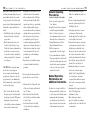
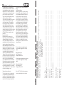
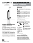
Figure 2
S PA R K P L U G A N D C A R B U R E T O R
Fuel Tank and
Plumbing
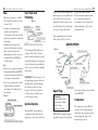
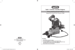
Figure 3
white), cord for earth to ground (green)
insulated plug cap, and cord (black and
red) for connection to a battery (not
included). You will also need to secure
an on/off switch (safety switch system)
of a capacity of more than 3 amps.
5
capacity of more than 1,000mA.
Be sure to mount the ignition system
in a location near the engine and
away from the receiver to prevent any
unwanted interference. Please refer to
the diagram below:
Saito recommends the use of a battery
with a voltage of 4.8V to 6V and a
The recommended fuel tank capacity
is between 350cc–450cc. Be sure to
include a reliable fuel filter in your fuel
system. The drawing above suggests use
of a fuel feed line and an air intake line.
Also, be sure to use fuel line compatible
with gasoline.
IMPORTANT: Air is necessary to cool
the engine during operation. Make sure
that sufficient air circulation through
the cowling is provided. As a basic
reference, the outlet area should be 3
to 5 times the area of the inlet area to
provide adequate cooling.
Ignition System
The Saito FG-36 comes with Saito’s
own ignition system composed of the
ignition unit, cord for sensor (black and
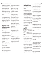
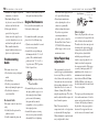
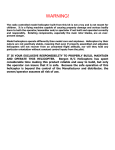
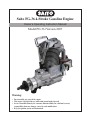
Figure 4
Spark Plug
Dimensions
Hexagon width = 14mm
Screw diameter = 10mm
Reach = 8.5mm
Spark gap = .7-.8mm
NGK-CM6 is the standard-equipped
plug with the engine. For replacement,
please replace with a product as reliable
as the NGK-CM6.
Carburetor
The carburetor used on the FG-36 is
exclusive to Saito and this particular
engine. Since it has a negative pressure
type fuel pump, the engine can be
mounted in any position.
6
B E F O R E S TA R T I N G T H E E N G I N E
CAUTION: If fuel remains in the
carburetor after flight, the components
made from rubber, such as the
diaphragm, will deteriorate over
time. After a flying session, it is best
to remove any fuel remaining in the
carburetor.
Do not needlessly disassemble the
carburetor. If you experience problems
with the carburetor, return it to the
Saito Horizon Service Center.
Preparation Before
Starting the Engine
(prior to break in)
• Mount the engine on a strong, parallelized test bench or on the aircraft. (In either case, the engine should be secured so it is immobile.)
• Check to make sure the throttle barrel will open and close completely.
• Check the wring of the ignition system to make sure it is connected correctly and securely.
• Use a 350cc to 450cc fuel tank on the test bench or in the aircraft.
• Make sure the fuel line is connected securely to the carburetor.
S TA R T I N G T H E E N G I N E
• For break in, use a fuel/oil mix ratio of 20:1.
• Mount an 18x8 or 19x8 carbon fiber propeller such as a Bolly or Mejzlik. Be sure it has been balanced.
• It is suggested you employ a spinner when using an electric starter. (Remember to check the tightness after every flight.)
• Use a tachometer to prevent over- revving of the engine.
• Be sure to connect a gasoline-proof line to the breather nipple to vent oil from the airframe.
• Check the battery of the electric starter to make sure it is fully charged. Be sure to use a safety on/off switch from the battery to the
ignition.
Starting the Engine
WARNING: Do not let people stand
in front of the engine while attempting
to start it. Also, make sure the engine
test bench or aircraft is completely
secure from movement.
Before you first start the engine, make
sure that the spark plug is screwed in
and tightened, and that the plug socket
cap is fitted in place and fastened
down properly. Fix the ignition sensor
in the proper position at the bottom
of the engine crankcase. The throttle
servo should be mounted at a distance
of 8 to 12 inches from the engine.
The spark plug cable must not touch
any part of the model structure as
(Assuming the engine is mounted in
an aircraft)
Saito’s FG-36 carburetor comes
adjusted to a basic setting. This
setting should be maintained during
the initial break-in runs. The standard
carburetor settings are as follows:
The high-speed needle valve is set to
about 2 1/3 turns from the fully closed
position. The low speed or idle needle
valve is set to about 4 turns out from
the fully closed position. Please refer
to the diagram below.
Figure 5
7
vibration may damage the shielded
cable. If this is not practical, it will
be necessary to provide an insulation
material for the cable. The ignition
unit itself should be wrapped in foam
rubber to prevent engine vibration
from damaging the electronic
components. All components must be
protected from contact with engine
fuel. Be sure to use an on/off (Safety
or “kill”) switch to allow the ignition
to be turned off and on.
IMPORTANT: Never turn the engine
over with the ignition turned on unless
the spark plug is inserted in the plug
socket. This could lead to ignition
damage.
Note: The Saito FG-36 is a 4-stroke
gasoline engine with a pumped
carburetor. You do not have to choke
the engine as you normally would a
2-stroke engine.
When you are ready to start the engine
switch the ignition on and set the
throttle to a slightly high idle speed.
We highly recommend the use of an
electric starter to start the FG-36.
Be sure to have a helper hold the
model securely.
8
S TA R T I N G T H E E N G I N E
a. Turn on the transmitter first, then the
receiver and check the operation of the
throttle servo and other controls.
b. Turn on power to the ignition
system.
c. Using an electric starter, begin
cranking the engine. It should fire
within seconds of applying the starter.
Allow the engine to idle for 30 to 45
seconds.
d. If the engine does not start, even
after using the electric starter to crank
the engine a second time, open the
throttle to maximum, turn off the
ignition and turn the engine over about
4 revolutions. Switch the ignition on
again and then restart the engine with
the throttle at a fast idle position.
e. If the engine still will not start,
unscrew the spark plug and check its
contacts. Clean any possible excess
fuel (i.e. an indication of engine
flooding) and screw it in again. Further
starting should only be done with the
throttle at idle position. If the plug
is dry, probably not enough fuel has
been drawn into the carburetor. If
that is the case, check the fuel feed
ADJUSTMENT OF THE CARBURETOR
and then return to the instructions in
paragraph a.
Note: We strongly urge the use of a
tachometer to check rpm readings
when breaking in the engine.
After starting and warming the engine
for 30 to 45 seconds adjust as follows:
For initial break in:
Do not exceed 4,000 rpm for the first
10 minutes of operation. This allows
all the parts to mate properly with
good lubrication.
Step I. Move the throttle to 2/3
high throttle position quickly (fast
acceleration). Repeat three times. If
the engine accelerates smoothly go to
Step III. If acceleration is not smooth,
go to Step II.
Step II. Faulty acceleration and a
tendency to quit is usually attributable
to a poor fuel mixture in the medium
rpm range. Stop the engine and
recheck the fuel feed (The fuel line
must not be pinched or broken).
Restart the engine and test acceleration
again. If the problem persists adjust
the carburetor. Open the low speed
needle by 5 minutes and retest. If
acceleration is smooth, open the
needle by another 3 to 5 minutes. This
should be done because the needle was
previously set too lean. If the engine
continues to not accelerate properly,
open the low-speed needle by 10
minutes. If the engine’s operation does
not improve, shut it off and check the
basic setting, restart the engine and
test the acceleration. If the engine
continues to not accelerate properly,
the defect is likely to lie somewhere
other than an adjustment. If the engine
runs correctly, go to Step III.
Step III. If the engine accelerates
correctly, set it at idle speed and
accelerate to full speed. Repeat twice
more. If the engine functions correctly,
go to Step IV. If it cuts out, open the
low-speed needle valve by 5 to 10
minutes more. If the engine does not
respond to acceleration fast enough,
keep closing the low-speed needle
until the engine starts to cut out in
response to throttle opening. At that
point, reopen the low speed needle by
5 to 10 minutes.
Step IV. If the engine reacts correctly,
set it at full speed. If the revolutions do
9
not drop, the engine has been adjusted
successfully. If the revolutions seem to
drop, open the high-speed needle by
about 5 to 10 minutes.
CAUTION: The engine must
be stopped while you adjust the
carburetor in order to prevent injury
by the propeller. Subsequent runs may
be made while slightly leaning out the
mixture with each tank full of fuel.
Forty minutes is considered sufficient
time for normal break in prior to the
first flight.
The use of a tachometer is encouraged
for setting the high-speed needle valve
prior to flight. The peak rpm should be
obtained and then reduced by 200 to
300 rpm. Over-revving of a 4-stroke
engine can cause internal damage to
the engine.
Adjustment of the
Carburetor
The low-speed needle valve is set at
the factory so that idle rpm may be
between 1,800 and 2,100 rpm.
In principle, a carburetor is adjusted
by first achieving peak rpm (highest
10
ADJUSTMENT OF THE CARBURETOR
rpms) with the high-speed needle valve
and then performing idling (low speed
rpms) with the throttle valve and the
low-speed needle valve. (Unless peak
rpm is achieved, idling adjustment will
be difficult to adjust and will not be
stable.)
• After filling the tank, start the engine and move the throttle to the fully open position.
• Turn the main needle valve screw clockwise (refer to Figure 5, page 7) with the carburetor adjustment bar (provided in accessories package) or a small screw driver, and adjust to achieve peak rpm. Use a tachometer to verify rpm.
CAUTION: Over-closing the main
needle valve is very dangerous
because it may cause knocking and
predetonation. It may also cause the
propeller nut to loosen. Immediately
turn the main needle counterclockwise
to richen up the setting.
• Next, close the throttle valve until the engine operates stably and with an idle rpm of around 1,700 rpm, by adjusting the low-speed needle valve with the carburetor adjustment bar (or small screwdriver) and N O R M A L O P E R AT I O N A N D M A I N T E N A N C E
manipulation of the throttle valve via the throttle stick on the transmitter.
• After reaching the stable 1,700 rpm, slowly open the throttle fully. If the rpms become slow or go up suddenly, adjust carefully until the changes are smooth from idle to peak rpm, by adjusting the low-speed needle valve.
• After the previous steps have been accomplished, repeat the process from idle to high rpm quickly. If the rpms do not reach peak, but stutter as the throttle moves from low to high,
re-tune the main needle valve and perform the process from idling to peak quickly.
• Repeat the process until the response is a smooth transition from idle to peak rpm.
General Operating
Proceducres
Factory settings for the main and lowspeed needle valves are as follows:
Normal Operation,
Maintenance and
Additional Information
• Main needle valve: Turn needle valve all the way clockwise and then back out 2 1/3 turns.
• Idle needle valve: Turn the needle valve all the way clockwise and then back out 4 turns.
• Set the throttle barrel at the fully closed position before making any adjustments.
to ensure the long life of the engine:
• Do not operate the engine with a “lean” mixture.
• Regularly check all screws and nuts on both the engine and muffler.
• After 1 to 2 hours of operation, valve adjustment may be necessary. Adjust the valves as shown in the Engine Maintenance and Valve/
Tappet Adjustment Sections.
• The Saito engines are equipped with a “breather” nipple. It is recommended that a length of Tygon type tubing be attached to this crankcase breather nipple and routed away from the engine compartment so the excess oil can be expelled outside of the aircraft.
• Be sure to do a range check before flying your model. It would be wise to do the range check with the engine
running and without it running. As a simple noise check, after the engine is started, lower the antenna of the transmitter and operate it 11
about 60 yards from the airplane. If there is no malfunction noted, it is normal.
• Be sure to charge the ignition battery and radio system battery before the first flight of the day.
• To discharge the waste oil, connect a gasoline-proof line from the breather nipple on the crankcase and vent it outside of the aircraft.
• Lubrication of the piston, connecting rod, bearings and cam gear is blow-
by lubrication, in which the oil in the fuel goes into the crankcase from the clearance between the cylinder and the piston. Engine life is directly affected by the property of the fuel/
oil mix. Please use reliable oil.
• Running the engine too lean causes heat; be sure to run the engine slightly “rich” from peak. Running too lean will cause “knocking” or engine failure and has an adverse effect on the connecting rod and the cam gear.
• Adjustment of the tappet is described in the “Valve/Tappet Gap Adjustment” section.
• When attaching an exhaust pipe to the cylinder or attaching a propeller nut, the use of threadlock is recommended.
12
TROUBLESHOOTING GUIDE
• Sometimes it is helpful to tighten an exhaust nut, etc. when hot.
• When finished flying for the day, be sure to remove fuel from the carburetor and the fuel tank.
• If the engine will not be operated for a long period of time, remove the plug, the rear cover, the cylinder-head cover, etc. and clean thoroughly and re-oil. Then assemble them in the original condition and place in a plastic or air- tight container.
Troubleshooting
Guide
If the engine does not start.
• Check and use a new spark plug if needed.
• Check fuel lines.
• Check for proper mechanical function by turning the engine over.
• Check that the carburetor is correctly installed.
Mechanical Faults
If the engine cannot be turned over
easily:
• It is likely that the piston in the cylinder is seized.
• Visually examine the piston and VA LV E / TA P P E T G A P A D J U S T M E N T
crankcase to find the likely cause of the engine's mechanical problem.
Engine Maintenence
Do not needlessly disassemble your
Saito single cylinder engine.
If you must disassemble your engine,
please refer to the following steps.
• Cylinder screws should be loosened in a criss-cross pattern.
• Assemble the cam gear lining up the timing mark at the “6 o’clock” position. The crankshaft must be positioned at the “12 o’clock” or “top dead center” (TDC) position. Refer to figure below:
Cam (Intake or Exhaust)
Bench Mark
• Reassemble the piston, rod, rocker arm, pins, pushrod, tappet, etc. in their original positions. Engine parts are mated after running the engine and they must be reassembled as close as possible to their original position.
• Assemble the engine, reversing the criss-cross pattern used in the disassembly. Prior to tightening each of the screws, apply a drop of oil to prevent thread damage.
• Normal engine maintenance, such as adjusting the valves or carburetor, is permissible without voiding the warranty. If you have any questions concerning maintenance
procedures, please contact the
Horizon/Saito Service Center at
877-504-0233. Our technicians will be happy to advise you on maintenance issues.
Valve/Tappet Gap
Adjustment
After approximately one hour of
operation, tappet gap adjustment may
be necessary. When you check the
valves, lubricate the moveable parts.
Also make sure the screw is in tight
before making adjustments to valves.
Adjust the valves to a clearance of
.03mm to .10mm (.002 to .004 in)
using the supplied gauge. The valves
must be adjusted with the engine cold
due to thermal expansion.
Note: Valves must be in the
compression stroke or closed position
as shown in the following figure.
When adjustment is completed, make
sure you tighten the lock nut.
Tappet Adjustment
13
Adjust between
0.03 – 0.10mm (.002" – .004")
Gauge
(0.1mm Max.)
Screw
How to Adjust
Remove the plug and the rocker arm
cover and revolve the propeller slowly
in the clockwise direction by hand.
The intake side rocker arm stops, and
by turning it, the piston reaches the
compression top dead center (TDC).
In that position, adjust with the
included gauge and hexagonal
wrench so tappet gap may be set to
almost zero when the engine is in
the compression stroke. If the gauge
can enter (a limit gauge with a 0.1
mm thickness), the clearance is at
maximum and needs adjustment,
adjust between 0.08 and 0.10mm
(0.002 to 0.004 in.) After the gap is
checked, tighten the lock nut securely.
Do not over-tighten.
The tappet gap is the most important
factor in the maintenance of 4-stroke
engines, and operation with an excess
clearance will degrade performance.
In particular, a large gap aggravates
abrasion of the tappet and the cam
and also increases the unusual sound.
14 C A R B U R E T O R M A I N T E N E N C E
Carburetor
Maintenence
Should you experience difficulty with
the carburetor of your engine:
• Remove the high-speed needle valve
and flush out the spray bar with clean
fuel. Replace the high-speed needle
valve.
• Factory settings for the idle needle
valve are about 4 turns out from a fully
closed position.
• The high-speed needle valve is set
to about 2 1/3 turns out from a fully
closed position and is a good point to
start from.
Generally speaking, there are very few
things that will keep today’s modern
gasoline engines from starting. To that
end, make sure you are using good
quality “fresh” fuel, the spark plug
is good and the ignition system is
working properly.
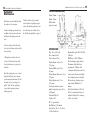
D I M E N S I O N S A N D S P E C I F I C AT I O N S
15
OUTSIDE DIMENSIONS (mm)
Length: 224mm
Check the battery voltage to make
sure the ignition is getting the proper
voltage. Should the engine fail to start
after these items are verified, refer to
the Troubleshooting Guide on page 12.
Height: 173mm Width: 85mm
(w/motor mount)
SPECIFICATIONS
Disp: 36.3cc (2.20 cu in)
Bore: 38mm (1.49 in)
Stroke: 32mm (1.26 in)
Weight: (Engine only); 48.2 oz
1252 grams
Weight: (Muffler only): 3.0 oz,
86 grams
Weight: (Engine Mount only): 9.6 oz,
270 grams
Weight: (Ignition only); 5.4 oz
(152 grams)
Total weight with motor mount,
muffler and ignition system: 66.2 oz
(1760 grams)
Crankshaft: M8x1.25
Cylinder: AAC
HP: 3.5 approximately
Fuel Efficiency: 30cc/minute
Propeller Size: Dia. 18- 19 x Pitch
8-9; Dia. 20x Pitch 8
Benchmark Propeller: APC 18x6W @
8,300 rpm
RPM Range: 1,700 – 9,000 rpm
Fuel Consumption: Approximately
30cc/minute at full throttle and
approximately 7,500 rpm. Fuel
consumption will depend on the load
of the propeller. During actual flight,
fuel consumption increases slightly.
Electrical usage of ignition system:
Approximately 200mAh for 15
minutes.
Fuel: Gasoline-Oil mix of 20:1–30:
(20:1 is recommended for break in
and first few flights. You can then go
to 30:1, if so desired.)
16
PA RT S L I S T
#
01
06
07
08 09
10
14
15
17
19
20A
22
23
27A
28
31
32
33
35
36A
37
38
39
40
41
description
WA R R A N T Y & R E PA I R S
S A I T O F G - 3 6 PA RT S L I S T
Cylinder (left)
Piston
Piston pin
Piston pin retainar
Piston ring
Connecting rod
Cylinder screw set (14-1, 14-2, 14-3, 14-4)
Crankcase
Rear cover
Breather nipple
Front bearing
Rear bearing
Crankshaft
Taper collet & Drive flange (27-1, 27-2)
Prop washer & Nut (28-1,28-2)
Crankcase screw set (31-1, 31-2, 31-3)
Engine gasket set (32-1, 32-2, 32-3, 32-4)
Cam gear housing
Cam gear
Cam gear shaft
Steel & Washer set (37-1, 37-2)
Tappet
Pushrod
Pushrod cover & rubber seal (40-1, 40-2, 40-3)
Rocker arm
QTy
#
1
1
1
2
1
1
1set
1
1
1
1
1
1
1ea
1ea
1set
1set
1
1
1
1set
2
2
2ea
2
42
43
44
45
46
47
48
49
69
74
75
80
82-1
83-1
90
91
93
95
110
149
152
153
description
Rocker arm screw and nut (42-1,42-2)
Rocker arm pin
Rocker arm bracket (left)
Rocker arm bracket (right)
Valve (in & out) (46-1, 46-2)
Valve spring+Keeper+Retainer (47-1,47-2,48)
Valve retainer (Cotter)
Rocker arm cover
Intake manifold
Muffler
Muffler manifold (75-1, 80)
Muffler nut
Carburetor complete
Carburetor body assembly
82-1-1, 82-1-2, 82-1-3, 82-1-4, 82-1-5
Carburetor screw & spring set
82-1-9, 82-1-10, 82-1-11, 82-1-12
Carburetor gasket set (82-1-6, 82-1-7, 82-1-8)
Intake velocity stack
Engine mount set (95-1, 95-2, 95-3, 95-4, 95-5)
Anti loosening nut
Oil slinger
Screw-pin (for drive flange setting)
Electronic ignition system
153-1, 153-2, 153-3, 153-4
QTY
2ea
2
1
1
2
2ea
4
2
1
1
1
2
1set
1set
1set
1set
1
1set
1
1
1
1set
17
Consumer Warranty and Repair Policy
Warranty Period:
Exclusive Warranty- Horizon Hobby, Inc.,
(Horizon) warranties that the Products
purchased (the "Product") will be free from
defects in materials and workmanship for a
period of 3 years from the date of purchase by
the Purchaser.
Limited Warranty
(a) This warranty is limited to the original
Purchaser ("Purchaser") and is not
transferable. REPAIR OR REPLACEMENT
AS PROVIDED UNDER THIS WARRANTY
IS THE EXCLUSIVE REMEDY OF THE
PURCHASER. This warranty covers only
those Products purchased from an authorized
Horizon dealer. Third party transactions
are not covered by this warranty. Proof of
purchase is required for warranty claims.
Further, Horizon reserves the right to change
or modify this warranty without notice and
disclaims all other warranties, express or
implied.
(b) Limitations- HORIZON MAKES NO
WARRANTY OR REPRESENTATION,
EXPRESS OR IMPLIED, ABOUT NONINFRINGEMENT, MERCHANTABILITY
OR FITNESS FOR A PARTICULAR
PURPOSE OF THE PRODUCT. THE
PURCHASER ACKNOWLEDGES THAT
THEY ALONE HAVE DETERMINED
THAT THE PRODUCT WILL SUITABLY
MEET THE
REQUIREMENTS OF THE PURCHASER’S
INTENDED USE.
(c) Purchaser Remedy- Horizon's sole
obligation hereunder shall be that Horizon
will, at its option, (i) repair or (ii) replace,
any Product determined by Horizon to be
defective. In the event of a defect, these are
the Purchaser's exclusive remedies. Horizon
reserves the right to inspect any and all
equipment involved in a warranty claim.
Repair or replacement decisions are at the sole
discretion of Horizon. This warranty does not
cover cosmetic damage or damage due to acts
of God, accident, misuse, abuse, negligence,
commercial use, or modification of or to any
part of the Product. This warranty does not
cover damage due to improper installation,
operation, maintenance, or attempted repair
by anyone other than Horizon. Return of
any goods by Purchaser must be approved in
writing by Horizon before shipment.
Damage Limits:
HORIZON SHALL NOT BE LIABLE
FOR SPECIAL, INDIRECT OR
CONSEQUENTIAL DAMAGES, LOSS
OF PROFITS OR PRODUCTION OR
COMMERCIAL LOSS IN ANY WAY
CONNECTED WITH THE PRODUCT,
WHETHER SUCH CLAIM IS BASED IN
CONTRACT, WARRANTY, NEGLIGENCE,
OR STRICT LIABILITY. Further, in no
event shall the liability of Horizon exceed
the individual price of the Product on which
liability is asserted. As Horizon has no control
over use, setup, final assembly, modification
or misuse, no liability shall be assumed nor
accepted for any resulting damage or injury.
By the act of use, setup or assembly, the user
accepts all resulting liability.
If you as the Purchaser or user are not
prepared to accept the liability associated with
the use of this Product, you are advised to
return this Product immediately in new and
unused condition to the place of purchase.
Law: These Terms are governed by Illinois
law (without regard to conflict of law
principals).
Safety Precautions:
This is a sophisticated hobby Product and
not a toy. It must be operated with caution
and common sense and requires some basic
mechanical ability. Failure to operate this
Product in a safe and responsible manner
could result in injury or damage to the
Product or other property. This Product
City/State/Zip________________________________________________________________________
Street Address________________________________________________________________________
Dealer’s Name________________________________________________________________________
Purchased From:
Daytime Phone Number________________________________________________________________ City/State/Zip________________________________________________________________________
Street Address________________________________________________________________________
Owner’s Name_ ______________________________________________________________________
Horizon Product Support
4105 Fieldstone Road
Champaign, Illinois 61822
Please cut on dotted line.
All other Products requiring warranty inspection
or repair should be shipped to the following
address:
Date of Purchase______________________________________________________________________
Please call 877-504-0233 with any questions or
concerns regarding this product or warranty.
Horizon Service Center
4105 Fieldstone Road
Champaign, Illinois 61822
Engine Type_ ________________________________________________________________________
Warranty Inspection and Repairs
To receive warranty service, you must include
your original sales receipt verifying the proofof-purchase date. Provided warranty conditions
have been met, your Product will be repaired or
replaced free of charge. Repair or replacement
Electronics and engines requiring inspection
or repair should be shipped to the following
address:
Complete this form and mail along with your dated sales receipt (send copy, keep original for your files)
within 10 days of purchase to: Horizon Service Center
Attn: Saito Warranty Dept.
4105 Fieldstone Road
Champaign, IL 61822
decisions are at the sole discretion of Horizon
Hobby.
Non-Warranty Repairs
Should your repair not be covered by warranty
the repair will be completed and payment will
be required without notification or estimate of
the expense unless the expense exceeds 50%
of the retail purchase cost. By submitting the
item for repair you are agreeing to payment of
the repair without notification. Repair estimates
are available upon request. You must include
this request with your repair. Non-warranty
repair estimates will be billed a minimum of ½
hour of labor. In addition you will be billed for
return freight. Please advise us of your preferred
method of payment. Horizon accepts money
orders and cashiers checks, as well as Visa,
MasterCard, American Express, and Discover
cards. If you choose to pay by credit card, please
include your credit card number and expiration
date. Any repair left unpaid or unclaimed after
90 days will be considered abandoned and will
be disposed of accordingly. Please note: nonwarranty repair is only available on electronics
and model engines.
Consumer Warranty Registration
WA R R A N T Y & R E PA I R S
is not intended for use by children without
direct adult supervision. The Product manual
contains instructions for safety, operation and
maintenance. It is essential to read and follow
all the instructions and warnings in the manual,
prior to assembly, setup or use, in order to
operate correctly and avoid damage or injury.
Questions, Assistance, and Repairs:
Your local hobby store and/or place of purchase
cannot provide warranty support or repair.
Once assembly, setup or use of the Product
has been started, you must contact Horizon
directly. This will enable Horizon to better
answer your questions and service you in the
event that you may need any assistance. For
questions or assistance, please direct your email
to [email protected], or call
877.504.0233 toll free to speak to a service
technician.
Inspection or Repairs
If this Product needs to be inspected or
repaired, please call for a Return Merchandise
Authorization (RMA). Pack the Product
securely using a shipping carton. Please note
that original boxes may be included, but are not
designed to withstand the rigors of shipping
without additional protection. Ship via a carrier
that provides tracking and insurance for lost or
damaged parcels, as Horizon is not responsible
for merchandise until it arrives and is accepted
at our facility. A Service Repair Request is
available at www.horizonhobby.com on the
“Support” tab. If you do not have internet access,
please include a letter with your complete name,
street address, email address and phone number
where you can be reached during business
days, your RMA number, a list of the included
items, method of payment for any non-warranty
expenses and a brief summary of the problem.
Your original sales receipt must also be included
for warranty consideration. Be sure your name,
address, and RMA number are clearly written on
the outside of the shipping carton.
✄
18
Distributed exclusively by
Horizon Hobby, Inc., Champaign, IL 61822
www.horizonhobby.com
© 2007
SAIMAN1LG
12102