1
User’s
Manual
AQ2200 Series
Multi-Application Test System
Startup Guide
IM 735101-01EN
5th Edition
Product Registration
Thank you for purchasing YOKOGAWA products.
YOKOGAWA provides registered users with a variety of information and
services.
Please allow us to serve you best by completing the product registration
form accessible from our homepage.
http://tmi.yokogawa.com/
PIM 103-03E
Foreword
Thank you for purchasing this AQ2200 Series Multi Application Test System. This user’
s manual explains the features, operating procedures, and handling precautions of
the AQ2200 Series. To ensure correct use, please read this manual thoroughly before
operation. Keep this manual in a safe place for quick reference in the event a question
arises.
In addition to this manual, the following seven kinds of manuals are provided for the
AQ2200 Series. Please read all manuals.
Manual Title
AQ2200 Series Multi Application
Test System
User’s Manual
(Startup Guide)
AQ2200 Series Multi Application
Test System
User’s Manual
(Frame and Module Operation)
AQ2200 Series Multi Application
Test System
User’s Manual
(Application Operation)
AQ2200 Series Multi Application
Test System
Communication Interface
User’s Manual
64 Mbit Program Pattern Option
User’s Manual
SDH/SONET Frame Option
User’s Manual
Checking the Package Contents
for AQ2200 Series Modules and
Module Handling Precautions
Notes
Manual No.
IM 735101-01EN
Description
This manual. This manual describes the
handling precautions for, the names and
functions of all parts of, and the firmware
upgrade procedure for the AQ2200 Series.
The supplied CD contains the PDF file of
this manual.
IM 735101-03EN The supplied CD contains the PDF file of
this manual. This manual describes all the
features of the AQ2200 Series and how to
use them, with the exception of some of the
application and communication features.
IM 735101-04EN The supplied CD contains the PDF file of
this manual. This manual describes the
AQ2200 Series application features and
how to use them.
IM735101-17EN
The supplied CD contains the PDF file of
this manual. This manual describes the
AQ2200 Series communication interface
features and how to use them.
IM 810518801-61E This manual describes how to create
program patterns for the AQ2200-601 10
Gbit/s BERT module with the /M option.
IM 810518801-62E This manual describes how to create SDH/
SONET patterns for the AQ2200-601 10
Gbit/s BERT module with the /P1 option.
IM 810518901-04E This is included with AQ2200 Series
modules. It explains the handling
precautions of the module and lists the
package contents.
• The contents of this manual are subject to change without prior notice as a result of
continuing improvements to the instrument’s performance and functions.
The figures given in this manual may differ from those that actually appear on your
screen.
• Every effort has been made in the preparation of this manual to ensure the accuracy
of its contents. However, should you have any questions or find any errors, please
contact your nearest YOKOGAWA dealer.
• Copying or reproducing all or any part of the contents of this manual without the
permission of YOKOGAWA is strictly prohibited.
5th Edition : November 2012 (YMI)
All Rights Reserved, Copyright ©2009, Yokogawa Electric Corporation
All Rights Reserved, Copyright ©2012, Yokogawa Meter & Instruments Corporation
IM 735101-01EN
Trademark Acknowledgements
• Adobe and Acrobat are registered trademarks or trademarks of Adobe Systems
Incorporated.
• Microsoft and Windows are registered trademarks or trademarks of Microsoft
Corporation in the United States and/or other countries.
• In this manual, the TM and ® symbols do not accompany their respective registered
trademark or trademark names.
• Other company and product names are registered trademarks or trademarks of their
respective holders.
Revisions
ii
•
•
•
•
•
1st Edition: Augast 2009
2nd Edition: November 2009
3rd Edition: January 2010
4th Edition: March 2010
5th Edition: November 2012
IM 735101-01EN
Checking the Package Contents
After receiving the product and opening the package, check the items described below.
If the wrong items have been delivered, if items are missing, or if there is a problem with
the appearance of the items, contact your nearest YOKOGAWA dealer. When contacting
the dealer from which you purchased the instrument, please give them the instrument
number.
Also, check that the model name and suffix code given on the name plate on the side
panel of the module are the same as those on your order.
AQ2211 Frame Controller
IN
N200
Complies with 21 CFR 1040.
10 and 1040.11 except for
deviations pursuant to
Laser Notice No.50, dated
June 24, 2007.
2-9-32 Nakacho,
Musashino-shi, Tokyo,
180-8750, Japan
OUT
REMOTE
INTERLOCK
TRIGGER
DATE OF
MANUFACTURE
□□□□ —□□ — □□
MODEL
SUFFIX
NO
100-240 V AC
170 VA MAX 50/60 Hz
Made in Japan
LINK/ACT
100 LINK
WARNING
Do not operate without reading
the safety precautions in the
user's manual.
USB
ETHERNET
GP-IB
(IEEE488)
AQ2212 Frame Controller
IN
OUT
REMOTE
INTERLOCK
TRIGGER
100-240 V AC
580 VA MAX 50/60 Hz
LINK/ACT
DATE OF
MANUFACTURE
100 LINK
WARNING
N200
USB
ETHERNET
GP-IB
(IEEE488)
Complies with 21 CFR 1040.10 and 1040.11 except for deviations
pursuant to Laser Notice No.50, dated June 24, 2007
2-9-32 Nakacho, Musashino-shi,Tokyo, 180-8750, Japan
Do not operate without reading the
safety precautions in the user's manual.
□□□□— □□— □□
MODEL
SUFFIX
NO
Made in Japan
AQ2211/AQ2212 Frame Controller
Model
735101
735102
Power cord
Suffix Code
-D
-F
-R
-Q
-H
Description
AQ2211 (Three slots)
AQ2212 (Nine slots)
UL,CSA Standard Power cord
VDE Standard power cord
AS Standard power cord
BS Standard power cord
GB Standard power cord (CCC-compatible)
No. (Instrument number)
When contacting the dealer from which you purchased the instrument, please give
them the instrument number.
Accessories
The instrument is shipped with the following accessories.
Product Name
Power cord
Interlock
connector plug
CD-ROM
(User’s manuals)
Printed manuals can be
purchased separately.
Contact your nearest
YOKOGAWA dealer to
purchase a copy.
User’s Manual
Rubber feet
IM 735101-01EN
Model or Part
No.
Quantity Notes
A1288JA
1
1
B8085NZ
1
IM 735101-01EN 1
A9088ZM
1
Includes the following user’s manuals:
•
Startup Guide
•
Frame and Module Operation
•
Application Operation
•
Communication Interface
This manual
iii
Checking the Package Contents
Power cord (One of the following power cords is included according to the suffix code)
A1006WD
(-D)
A1009WD
(-F)
Interlock connector plug
A1288JA
A1054WD
(-Q)
A1024WD
(-R)
User’s manual (this manual)
IM 735101-01EN
A1064WD
(-H)
User’s manual
B8085NZ (CD-ROM)
Rubber feet
A9088ZM
Optional Accessories (Sold separately)
The following optional accessories are available for purchase separately. For information
about ordering accessories, contact your nearest YOKOGAWA dealer.
Product Name
AQ2200-901 blank panel
AQ2211 rack mount kit
Model or Part No.
810518926
735182-03
AQ2212 rack mount kit
735182-09
Specifications
1-slot size
For mounting one AQ2211 to the left
side of an EIA-standard rack.
For mounting one AQ2212 to an EIAstandard rack.
How to Use the CD-ROM (User’s Manuals)
The CD-ROM contains PDF files of the following user’s manuals.
• AQ2200 Series Multi-Application Test System User’s Manual
(Startup Guide) IM 735101-01EN
• AQ2200 Series Multi-Application Test System User’s Manual
(Frame and Module Operation) IM 735101-03EN
• AQ2200 Series Multi-Application Test System User’s Manual
(Application Operation) IM 735101-04EN
• AQ2200 Series Multi-Application Test System Communication Interface User’s Manual
IM 735101-17EN
To view the manuals above, you need Adobe Reader 5.0 or later.
WARNING
Never play this CD-ROM in an audio CD player.
Doing so may cause loss of hearing or speaker damage due to the high-volume
sound that may be produced.
iv
IM 735101-01EN
Safety Precautions
This instrument is an IEC safety class I instrument (provided with a terminal for protective
earth grounding).
The general safety precautions described herein must be observed during all phases
of operation. If the instrument is used in a manner not specified in this manual, the
protection provided by the instrument may be impaired. YOKOGAWA assumes no liability
for the customer’s failure to comply with these requirements.
The following symbols are used on this instrument.
Handle with care. To protect the instrument and its users, refer to the explanation
in the User’s Manual or Service Manual.
Alternating current
Power-on state
Power-off state
Laser radiation hazard
Power on
Power off
IM 735101-01EN
Safety Precautions
Failure to comply with the precautions below could lead to injury or death or
damage to the instrument.
WARNING
Use the Instrument Only for Its Intended Purpose
This optical measuring instrument is designed to measure the optical characteristics
of light sources and evaluate their performance. Do not use this instrument for
anything other than as an optical measuring instrument.
Check the Physical Appearance
Do not use the instrument if there is a problem with its physical appearance.
Power Supply
Make sure that the power supply voltage matches the instrument’s rated supply
voltage and that it does not exceed the maximum voltage range specified for the
power cord.
Use the Correct Power Cord and Plug
To prevent fire and electric shock, use only a power cord supplied by YOKOGAWA.
The main power plug must be plugged into an outlet with a protective earth
terminal. The earth protection will be nullified if you use an ungrounded extension
cord.
Connect to a Protective Earth Terminal
To prevent electric shock, be sure to connect to a protective earth terminal before
turning on the frame controller’s power. The power cord that comes with the frame
controller is a three-prong cord. Connect the power cord to a properly grounded
three-prong outlet.
Do Not Impair the Protective Grounding
Never cut off the frame controller’s internal or external protective earth wire or
disconnect the wiring to the protective earth terminal. Doing so may result in
electric shock or damage to the instrument.
Do Not Operate with Defective Protective Grounding or Fuses
Do not operate the frame controller if its protective grounding or one of its fuses
might be defective. Check the grounding and the fuses before operating the frame
controller.
Do Not Operate in an Explosive Atmosphere
Do not operate the instrument in the presence of flammable gasses or vapors.
Doing so is extremely dangerous.
Do Not Remove Covers
Only qualified YOKOGAWA personnel should remove the instrument’s covers. The
inside of the frame controller is dangerous because parts of it have high voltages.
Ground the Instrument before Making External Connections
Securely connect the protective grounding before connecting to the item under
measurement or to an external control unit. Before touching a circuit, turn off its
power and check that it has no voltage.
vi
IM 735101-01EN
Safety Precautions
Avoid Electric Shock When Using the Modules
Do not apply an input voltage that exceeds the maximum input voltage, withstand
voltage, or allowable surge voltage.
To prevent the possibility of electric shock, be sure to fasten the screws that are at
the bottom of the front panel of 2-slot and 3-slot modules. Otherwise, the electrical
and mechanical protection functions will not be activated.
Do not leave the modules connected to the instrument in environments in which a
voltage equal to or greater than the allowable surge voltage may occur.
Dispose the Instrument Properly
Do not throw this instrument into a fire to dispose of it. Doing so may cause the
instrument to explode, resulting in fire or personal injury.
The devices used in this instrument contain gallium arsenide (GaAs) and indium
phosphide (InP). When you dispose this instrument, you must separate it from
general industrial waste and household garbage, and dispose of it according to
local regulations.
Additionally, gallium arsenide powder and vapor are dangerous substances. Do not
burn, cut, crush, chemically disassemble, or otherwise destroy this instrument.
This instrument is a “Class 1M Laser Product” as Defined in “IEC60825-1,
2007.”
Never look at the optical output section or the end of the optical fiber that is
connected to the optical output section during laser beam generation. Using
an optical instrument, such as a loupe, magnifying glass, or microscope, when
observing the laser beam from a distance of less than 100 mm may cause eye
injury. The laser beam that this instrument uses cannot be seen by the human eye.
However, the laser beam is extremely hazardous to the human eye and eyesight if
it happens to hit the eye.
Install or Use the Instrument in Appropriate Locations
• Do not install or use the instrument outdoors or in locations subject to rain or
water.
• Install the instrument so that you can immediately remove the power cord if an
abnormal or dangerous condition occurs.
CAUTION
Operating Environment Limitations
This is a class A instrument designed for an industrial environment. Operation of
this equipment in a residential area can cause radio interference, in which case
users will be required to correct the interference.
IM 735101-01EN
vii
Safety Precautions
Safety Precautions for Laser Products
This instrument uses a laser light source. This instrument is a Class 1M laser product as
defined by IEC60825-1 Safety of Laser Products—Part1: Equipment Classification and
Requirements. In addition, this instrument complies with 21 CFR 1040.10 and 1040.11
except for deviations pursuant to Laser Notice No. 50, dated June 24, 2007.
Laser Class 1M Label
Using an optical instrument, such as a loupe,
magnifying glass, or microscope, when
observing the laser beam from a distance of
less than 100 mm may cause eye injury.
Laser Class 1 Label
Using an optical instrument, such as a loupe,
magnifying glass, or microscope, when
observing the laser beam from a distance of
less than 100 mm may cause eye injury.
Model
Class Laser
Type
Center Wavelength
810518901
810518902
810518903
810518904
AQ2200131
AQ2200132
1M
1
1
1M
1M
1M
1310 to 1650 nm
1310/1550 nm
1310/1550 nm
1440 to 1640 nm
1527.60 to 1608.76 nm
1527.60 to 1608.76 nm
DFB-Laser
FP-Laser
FP-Laser
EC-Laser
ITLA
ITLA
CLASS 1 LASER PRODUCT
(IEC 60825-1:2007)
Maximum
Output
Power
40 mW
10 mW
10 mW
50.2 mW
40 mW
40 mW
Mode Field
Diameter
Numerical
Aperture
9 μm
9 μm
9 μm
9 μm
9 µm
9 µm
0.1
0.1
0.1
0.1
0.1
0.1
Note
• Commercially available XFP transceivers installed in the AQ2200-641 XFP Interface Module
are not covered under warranty.
• For save handling of the laser, consult the user’s manual that came with the XFP
transceiver.
viii
IM 735101-01EN
Waste Electrical and Electronic Equipment
Waste Electrical and Electronic Equipment (WEEE), Directive 2002/96/EC
(This directive is only valid in the EU.)
This product complies with the WEEE Directive (2002/96/EC) marking
requirement. This marking indicates that you must not discard this electrical/
electronic product in domestic household waste.
Product Category
With reference to the equipment types in the WEEE directive Annex 1, this
product is classified as a “Monitoring and Control instrumentation” product.
Do not dispose in domestic household waste. When disposing products in the EU,
contact your local Yokogawa Europe B. V. office.
New EU Battery Directive
New EU Battery Directive, DIRECTIVE 2006/66/EC
(This directive is valid in the EU only.)
Batteries are included in this product. This marking indicates they shall be sorted
out and collected as ordained in ANNEX II in DIRECTIVE 2006/66/EC.
Battery type
Lithium battery
You cannot replace batteries by yourself. When you need to replace batteries,
contact your local Yokogawa Europe B.V.office.
IM 735101-01EN
ix
Conventions Used in This Manual
Notes and Cautions
The notes and cautions in this manual are categorized using the following symbols.
Improper handling or use can lead to injury to the user or damage
to the instrument. This symbol appears on the instrument to indicate
that the user must refer to the user’s manual for special instructions.
The same symbol appears in the corresponding place in the user’
s manual to identify those instructions. In the manual, the symbol is
used in conjunction with the word “WARNING” or “CAUTION.”
WARNING
Calls attention to actions or conditions that could cause serious or
fatal injury to the user, and precautions that can be taken to prevent
such occurrences.
CAUTION
Calls attention to actions or conditions that could cause light injury
to the user, or cause damage to the instrument or user’s data, and
precautions that can be taken to prevent such occurrences.
Note
Calls attention to information that is important for proper operation of
the instrument.
Character Notations
Bold characters in procedural explanations are used to indicate panel keys and soft keys
that are used in the procedure and menu items that appear on the screen.
IM 735101-01EN
Contents
1
Foreword.............................................................................................................................................i
Checking the Package Contents...................................................................................................... iii
Safety Precautions.............................................................................................................................v
Waste Electrical and Electronic Equipment...................................................................................... ix
New EU Battery Directive................................................................................................................. ix
Conventions Used in This Manual.....................................................................................................x
Module Model Name, Suffix Code, and Accessories...................................................................... xiii
Chapter 1 Component Names and Functions
1.1
1.2
1.3
1.4
1.5
1.6
1.7
1.8
1.9
1.10
1.11
1.12
Frame Controller............................................................................................................... 1-1
Light Source Modules........................................................................................................ 1-5
Optical Sensor Modules.................................................................................................... 1-8
ORL Module.....................................................................................................................1-11
Attenuator Modules......................................................................................................... 1-12
Optical Switch Modules................................................................................................... 1-14
BERT Module.................................................................................................................. 1-17
Optical Modulator Modules.............................................................................................. 1-18
Optical Receiver Module................................................................................................. 1-19
XFP Interface Module...................................................................................................... 1-20
Transceiver I/F Module.................................................................................................... 1-21
SG Module...................................................................................................................... 1-22
Chapter 2 Making Preparations for Measurements
2.1
2.2
2.3
2.4
2.5
2.6
2.7
2.8
Handling Precautions........................................................................................................ 2-1
Installing the Instrument.................................................................................................... 2-3
Attaching and Removing Blank Panels............................................................................. 2-6
Installing and Uninstalling Modules................................................................................... 2-7
Connecting Cables........................................................................................................................................2-10
Connecting and Disconnecting Connector Adapters....................................................... 2-19
Connecting Optical Fiber Cables.............................................................................................................2-22
Connecting to the Power Supply............................................................................................................2-23
Chapter 3 External Input and Output
3.1
3.2
3.3
3.4
3.5
3.6
3.7
3.8
IM 735101-01EN
Frame Controller.............................................................................................................................................. 3-1
Optical Sensor Modules.................................................................................................... 3-3
BERT Module...................................................................................................................................................... 3-4
Optical Modulator Module.......................................................................................................................... 3-8
Optical Receiver Module............................................................................................................................... 3-9
XFP Interface Module...................................................................................................................................3-10
Transceiver I/F Module................................................................................................................................3-12
SG Module........................................................................................................................................................3-14
xi
2
3
4
5
Index
7
8
9
10
Contents
Chapter 4 Troubleshooting, Maintenance, and Inspection
4.1
4.2
4.3
4.4
4.5
4.6
4.7
Troubleshooting................................................................................................................. 4-1
Error Messages................................................................................................................. 4-6
Changing Modules.......................................................................................................... 4-16
Updating the Firmware.................................................................................................... 4-19
Routine Maintenance...................................................................................................... 4-27
Recommended Replacement Parts................................................................................ 4-34
Calibration....................................................................................................................... 4-35
Chapter 5 Specifications
5.1
5.2
5.3
5.4
5.4
5.5
5.6
5.7
5.8
5.9
5.10
5.11
5.12
5.13
5.14
5.15
5.16
5.17
5.18
5.19
5.20
5.21
5.20
AQ2211/AQ2212 Frame Controller................................................................................... 5-1
AQ2200-111 DFB-LD Module............................................................................................ 5-3
AQ2200-141/142 FP-LD Module....................................................................................... 5-6
AQ2200-131/132 Grid TLS Module................................................................................... 5-7
AQ2200-136 TLS Module.................................................................................................. 5-8
AQ2200-201 Interface Module.......................................................................................... 5-9
AQ2200-211 Sensor Module........................................................................................... 5-10
AQ2200-215 Sensor Module........................................................................................... 5-12
AQ2200-221 Sensor Module........................................................................................... 5-14
AQ2200-231/241 Optical Sensor Head........................................................................... 5-16
AQ2200-271 ORL Module............................................................................................... 5-19
AQ2200-311 ATTN Module.............................................................................................. 5-20
AQ2200-311A ATTN Module........................................................................................... 5-21
AQ2200-331 ATTN Module............................................................................................. 5-22
AQ2200-411/412 OSW Module....................................................................................... 5-24
AQ2200-421 OSW Module.............................................................................................. 5-25
AQ2200-601 10 Gbit/s BERT Module............................................................................. 5-26
AQ2200-621/622 10 Gbit/s Optical Modulator................................................................ 5-29
AQ2200-631 10 Gbit/s Optical Receiver......................................................................... 5-30
AQ2200-641 XFP Interface Module................................................................................ 5-31
AQ2200-642 Transceiver I/F Module.............................................................................. 5-32
AQ2200-651 SG Module................................................................................................. 5-34
External Dimensions....................................................................................................... 5-35
Index
xii
IM 735101-01EN
Module Model Name, Suffix Code, and Accessories
AQ2200-111 DFB-LD Module
Model
810518901
Wavelength
Optical connector
Optical output level
Optical fiber
External modulation
Suffix Code
Description
See section 5.2 for the list of supported
wavelengths
1310 nm
1490 nm
FC/Angled PC connector
10 mW optical output
20 mW optical output
SM fiber
PM fiber
No external modulation
External modulation (sine)
External modulation (chop)
-Mxxxx
-W1310
-W1490
-FCA
-P10
-P20
-SMF
-PMF
-MODN
-MODS
-MODC
Accessories
The instrument is shipped with the following accessories.
Product Name
User’s manual
Model or Part
No.
IM
810518901-04E
Quantity
Notes
1
Read before using the instrument
AQ2200-141 FP-LD Module
Model
810518902
Wavelength
Optical connector
Suffix Code
Description
1310 nm
1550 nm
AQ9441(FC) universal adapter
AQ9441(SC) universal adapter
-W1310
-W1550
/FCC
/SCC
Accessories
The instrument is shipped with the following accessories.
Product Name
User’s manual
Model or Part
No.
IM
810518901-04E
Quantity
Notes
1
Read before using the instrument
Optional Accessories
The following optional accessories are available for purchase separately.
Product Name
AQ9441(FC) universal adapter
AQ9441(SC) universal adapter
IM 735101-01EN
Model
813917321-FCC
813917321-SCC
Notes
FC connector
SC connector
xiii
Module Model Name, Suffix Code, and Accessories
AQ2200-142 DUAL FP-LD Module
Model
810518903
Wavelength
Optical connector
Suffix Code
-W135D
/FCC
/SCC
Description
1310/1550 nm
AQ9441(FC) universal adapter
AQ9441(SC) universal adapter
Accessories
The instrument is shipped with the following accessories.
Product Name
User’s manual
Model or Part
No.
IM
810518901-04E
Quantity
Notes
1
Read before using the instrument
Optional Accessories
The following optional accessories are available for purchase separately.
Product Name
AQ9441(FC) universal adapter
AQ9441(SC) universal adapter
xiv
Model
813917321-FCC
813917321-SCC
Notes
FC connector
SC connector
IM 735101-01EN
Module Model Name, Suffix Code, and Accessories
AQ2200-131 Grid TLS Module
Model
AQ2200131
Wavelength
LD type
Optical fiber
Optical connector
Suffix Code
-C
-L
-T4
-T2
-PA
-FCC
-FCA
Description
C-band
L-band
Standard type
Advanced type (Fine tuning)
PM fiber
FC/PC connector
FC/Angled PC connector
Accessories
The instrument is shipped with the following accessories.
Product Name
User’s manual
Model or Part
No.
IM
810518901-04E
Quantity
Notes
1
Read before using the instrument
AQ2200-132 Grid TLS Module
Model
AQ2200132
Wavelength
LD type
Optical fiber
Optical connector
Suffix Code
-CC
-LL
-CL
-T4
-T2
-PA
-FCC
-FCA
Description
CH1:C-band, CH2:C-band
CH1:L-band, CH2:L-band
CH1:C-band, CH2:L-band
Standard type
Advanced type (Fine tuning)
PM fiber
FC/PC connector
FC/Angled PC connector
Accessories
The instrument is shipped with the following accessories.
Product Name
User’s manual
Model or Part
No.
IM
810518901-04E
Quantity
Notes
1
Read before using the instrument
AQ2200-136 TLS Module
Model
810518904
Optical connector
Optical fiber
Wavelength
Suffix Code
-FCA
-SMF
-WLSTD
Description
FC/Angled PC connector
SM fiber
Changeable
Accessories
The instrument is shipped with the following accessories.
Product Name
User’s manual
IM 735101-01EN
Model or Part
No.
IM
810518901-04E
Quantity
Notes
1
Read before using the instrument
xv
Module Model Name, Suffix Code, and Accessories
AQ2200-201 Interface Module
Model
810518905
Suffix Code
Description
Accessories
The instrument is shipped with the following accessories.
Product Name
Analog out plug
Optical sensor head connector
cable
User’s manual
Model or Part No. Quantity Notes
955-230002662
1
955-850002026
1
Optical sensor head
connector cable
955-850002026
Analog out plug
955-230002662
IM 810518901-04E 1
Read before using the
instrument
Optional Accessories
The following optional accessories are available for purchase separately.
Product Name
Analog out plug
Part No.
955-230002662
Notes
AQ2200-231 Optical Sensor Head
Model
810518906
Connector adapter
Suffix Code
/FCC
/SCC
/STC
Description
Large-aperture, long-wavelength sensor
AQ9355C (FC) connector adapter with a light shielding cap
AQ9335C (SC) connector adapter with a light shielding cap
AQ9335C (ST) connector adapter with a light shielding cap
Accessories
The instrument is shipped with the following accessories.
Product Name
User’s manual
Model or Part No. Quantity
IM 810518901-04E 1
Notes
Read before using the instrument
Optional Accessories
The following optional accessories are available for purchase separately.
xvi
Product Name
AQ9335C (FC) connector adapter
AQ9335C (SC) connector adapter
AQ9335C (ST) connector adapter
AQ9335C (LC) connector adapter
AQ9335C (MU) connector adapter
Model or Part No.
810518909-FCC
810518910-SCC
810518911-STC
M3407JD
M3407JE
Light shielding cap (FC)
Light shielding cap (SC)
Light shielding cap (ST)
AQ9346 tape fiber adapter
AQ9302 (125) bare fiber adapter
AQ9440B MT connector
Dust protection cap (LC)
Dust protection cap (MU)
810518912-FCC
810518913-SCC
810518914-STC
810517917
819705500-0125
810517921-B
M3407HD
M3407HE
Notes
FC connector
SC connector
ST connector
LC connector with a dust protection cap
MU connector with a dust protection
cap
Light shielding cap for an FC connector
Light shielding cap for an SC connector
Light shielding cap for an ST connector
2, 4, 8, and 12 cores
Dust protection cap for an LC connector
Dust protection cap for an MU
connector
IM 735101-01EN
Module Model Name, Suffix Code, and Accessories
AQ2200-241 Optical Sensor Head
Model
810518907
Connector adapter
Suffix Code
Description
Large-aperture, short-wavelength sensor
AQ9355C (FC) connector adapter with a light
shielding cap
AQ9335C (SC) connector adapter with a light
shielding cap
AQ9335C (ST) connector adapter with a light
shielding cap
/FCC
/SCC
/STC
Accessories
The instrument is shipped with the following accessories.
Product Name
User’s manual
Model or Part No.
IM 810518901-04E
Quantity
1
Notes
Read before using the instrument
Optional Accessories
The following optional accessories are available for purchase separately.
IM 735101-01EN
Product Name
AQ9335C (FC) connector adapter
AQ9335C (SC) connector adapter
AQ9335C (ST) connector adapter
AQ9335C (LC) connector adapter
Model or Part No.
810518909-FCC
810518910-SCC
810518911-STC
M3407JD
AQ9335C (MU) connector adapter
M3407JE
Light shielding cap (FC)
810518912-FCC
Light shielding cap (SC)
810518913-SCC
Light shielding cap (ST)
810518914-STC
AQ9346 tape fiber adapter
AQ9302 (125) bare fiber adapter
AQ9440B MT connector
Dust protection cap (LC)
810517917
819705500-0125
810517921-B
M3407HD
Dust protection cap (MU)
M3407HE
Notes
FC connector
SC connector
ST connector
LC connector with a dust
protection cap
MU connector with a dust
protection cap
Light shielding cap for an FC
connector
Light shielding cap for an SC
connector
Light shielding cap for an ST
connector
2, 4, 8, and 12 cores
Dust protection cap for an LC
connector
Dust protection cap for an MU
connector
xvii
Module Model Name, Suffix Code, and Accessories
AQ2200-211 Sensor Module
Model
810518908
Connector adapter
Suffix Code
/FCC
/SCC
/STC
Description
Highly sensitive, long-wavelength sensor
AQ9447 (FC) connector adapter with a light
shielding cap
AQ9447 (SC) connector adapter with a light
shielding cap
AQ9447 (ST) connector adapter with a light
shielding cap
Accessories
The instrument is shipped with the following accessories.
Product Name
Analog out plug
User’s manual
Model or Part Quantity Notes
No.
955-230002662 1
IM
1
Read before using the
810518901-04E
instrument
Analog out plug
955-230002662
Optional Accessories
The following optional accessories are available for purchase separately.
xviii
Product Name
AQ9447 (FC) connector adapter
AQ9447 (SC) connector adapter
AQ9447 (ST) connector adapter
Light shielding cap (FC)
Model or Part No.
810804602-FCC
810804602-SCC
810804602-STC
810518912-FCC
Light shielding cap (SC)
810518913-SCC
Light shielding cap (ST)
810518914-STC
AQ9346 tape fiber adapter
AQ9302 (125) bare fiber adapter
AQ9440B MT connector
Analog out plug
810517917
819705500-0125
810517921-B
955-230002662
Notes
FC connector
SC connector
ST connector
Light shielding cap for an FC
connector
Light shielding cap for an SC
connector
Light shielding cap for an ST
connector
2, 4, 8, and 12 cores
IM 735101-01EN
Module Model Name, Suffix Code, and Accessories
AQ2200-215 Sensor Module
Model
735125
Connector adapter
Suffix Code
Description
High power sensor
No connector adapter
AQ9335C (FC) connector adapter with a light
shielding cap
AQ9335C (SC) connector adapter with a light
shielding cap
AQ9335C (ST) connector adapter with a light
shielding cap
AQ9335C (LC) connector adapter with a dust
protection cap
AQ9335C (MU) connector adapter with a dust
protection cap
-NON
-FCC
-SCC
-STC
-LCC
-MUC
Accessories
The instrument is shipped with the following accessories.
Product Name
User’s manual
Model or Part
No.
IM
810518901-04E
Quantity
Notes
1
Read before using the instrument
Optional Accessories
The following optional accessories are available for purchase separately.
IM 735101-01EN
Product Name
AQ9335C (FC) connector adapter
AQ9335C (SC) connector adapter
AQ9335C (ST) connector adapter
AQ9335C (LC) connector adapter
Model or Part No.
810518909-FCC
810518910-SCC
810518911-STC
M3407JD
AQ9335C (MU) connector adapter
M3407JE
Light shielding cap (FC)
810518912-FCC
Light shielding cap (SC)
810518913-SCC
Light shielding cap (ST)
810518914-STC
Dust protection cap (LC)
M3407HD
Dust protection cap (MU)
M3407HE
Notes
FC connector
SC connector
ST connector
LC connector with a dust
protection cap
MU connector with a dust
protection cap
Light shielding cap for an FC
connector
Light shielding cap for an SC
connector
Light shielding cap for an ST
connector
Dust protection cap for an LC
connector
Dust protection cap for an MU
connector
xix
Module Model Name, Suffix Code, and Accessories
AQ2200-221 Sensor Module
Model
735122
Connector adapter
Suffix Code
-NON
-FCC
-SCC
-STC
-LCC
-MUC
Description
Two-channel, long-wavelength sensor
No connector adapter
AQ9335C (FC) connector adapter with a light
shielding cap
AQ9335C (SC) connector adapter with a light
shielding cap
AQ9335C (ST) connector adapter with a light
shielding cap
AQ9335C (LC) connector adapter with a dust
protection cap
AQ9335C (MU) connector adapter with a dust
protection cap
Accessories
The instrument is shipped with the following accessories.
Product Name
Model or Part
No.
IM
810518901-04E
User’s manual
Quantity
Notes
1
Read before using the instrument
Optional Accessories
The following optional accessories are available for purchase separately.
Product Name
AQ9335C (FC) connector adapter
AQ9335C (SC) connector adapter
AQ9335C (ST) connector adapter
AQ9335C (LC) connector adapter
Model or Part No.
810518909-FCC
810518910-SCC
810518911-STC
M3407JD
AQ9335C (MU) connector adapter
M3407JE
Light shielding cap (FC)
810518912-FCC
Light shielding cap (SC)
810518913-SCC
Light shielding cap (ST)
810518914-STC
Dust protection cap (LC)
M3407HD
Dust protection cap (MU)
M3407HE
Notes
FC connector
SC connector
ST connector
LC connector with a dust
protection cap
MU connector with a dust
protection cap
Light shielding cap for an FC
connector
Light shielding cap for an SC
connector
Light shielding cap for an ST
connector
Dust protection cap for an LC
connector
Dust protection cap for an MU
connector
AQ2200-271 ORL Module
Model
735185
Optical fiber
Suffix Code
Description
-SA
SMF (10/125)
Accessories
The instrument is shipped with the following accessories.
Product Name
User’s manual
xx
Model or Part
No.
IM
810518901-04E
Quantity
Notes
1
Read before using the instrument
IM 735101-01EN
Module Model Name, Suffix Code, and Accessories
Optional Accessories
The following optional accessories are available for purchase separately.
Product Name
ORL master cord
ORL master cord
ORL master cord
Part No.
955-300001169
955-300001170
955-300900506
Notes
FC connector
SC connector
Open
AQ2200-311 ATTN Module
Model
810518915
Optical connector
Monitor port option
Suffix Code
Description
-FCC
-SCC
-FCA
-SCA
/MON
FC/PC connector
SC/PC connector
FC/Angled PC connector
SC/Angled PC connector
Monitor port included
Accessories
The instrument is shipped with the following accessories.
Product Name
User’s manual
Model or Part
No.
IM
810518901-04E
Quantity
Notes
1
Read before using the instrument
AQ2200-311A ATTN Module
Model
735131
Optical fiber
Optical connector
Monitor port option
Suffix Code
Description
-SA
-G6
-FCC
-SCC
/MON
SMF (10/125)
MMF (62.5/125)
FC/PC connector
SC/PC connector
Monitor port included
Accessories
The instrument is shipped with the following accessories.
Product Name
User’s manual
Model or Part
No.
IM
810518901-04E
Quantity
Notes
1
Read before using the instrument
AQ2200-331 ATTN Module
Model
735133
Optical fiber
Optical connector
Suffix Code
-SA
-G6
-FCC
-SCC
Description
Built-in optical power meter
SMF (10/125)
MMF (62.5/125)
FC/PC connector
SC/PC connector
Accessories
The instrument is shipped with the following accessories.
Product Name
User’s manual
IM 735101-01EN
Model or Part
No.
IM
810518901-04E
Quantity
Notes
1
Read before using the instrument
xxi
Module Model Name, Suffix Code, and Accessories
AQ2200-411 OSW Module
Model
735141
Port configuration
Suffix Code
Description
1 × 4 or 1 × 8
1×4
1×8
SMF (10/125)
MMF (62.5/125)
FC/PC connector
SC/PC connector
-04
-08
Optical fiber
-SA
-G6
-FCC
-SCC
Optical connector
Accessories
The instrument is shipped with the following accessories.
Product Name
User’s manual
Model or Part
No.
IM
810518901-04E
Quantity
Notes
1
Read before using the instrument
AQ2200-412 OSW Module
Model
735143
Port configuration
Optical fiber
Optical connector
Suffix Code
Description
1 × 16
1 × 16
SMF (10/125)
FC/PC connector
SC/PC connector
-16
-SA
-FCC
-SCC
Accessories
The instrument is shipped with the following accessories.
Product Name
User’s manual
Model or Part
No.
IM
810518901-04E
Quantity
Notes
1
Read before using the instrument
AQ2200-421 OSW Module
Model
735142
Port configuration
Optical fiber
Optical connector
Suffix Code
Description
1 × 2 or 2 × 2
1×2
2×2
SMF (10/125)
MMF (62.5/125)
FC/PC connector
SC/PC connector
-21
-22
-SA
-G6
-FCC
-SCC
Accessories
The instrument is shipped with the following accessories.
Product Name
User’s manual
xxii
Model or Part
No.
IM
810518901-04E
Quantity
Notes
1
Read before using the instrument
IM 735101-01EN
Module Model Name, Suffix Code, and Accessories
AQ2200-601 10 Gbit/s BERT Module
Model
810518801
Options
Suffix Code
Description
/M
PC software for creating 64 Mbit program
patterns
PC software for creating SDH/SONET frame
patterns
/P1
Accessories
The instrument is shipped with the following accessories.
Product Name
User’s manual
Protective cap
Model or Part No.
IM 810518901-04E
-
Quantity
1
5
Terminator for circuit
protection
-
6
Notes
Read before using the instrument
Protective caps are already
attached to the input terminals.
Terminators are already attached to
the output terminals.
AQ2200-621 10 Gbit/s Optical modulator
Model
810518802
Crystal orientation of
the LN modulator
Suffix Code
Description
1.55 μm
X-cut
-A
-B
Optical connector
Z-cut
SC connector
FC connector
PMF (FC-SC) for 1.5 μm
U-link coaxial cable
-S
-F
Cable
/P
/U
Accessories
The instrument is shipped with the following accessories.
Product Name
User’s manual
Protective cap
Model or Part No.
IM 810518901-04E
-
Quantity
1
2
Terminator for circuit
protection
-
1
Notes
Read before using the instrument
Protective caps are already
attached to the optical signal
terminals.
Terminator is already attached to
the electrical terminal.
AQ2200-622 10 Gbit/s Optical Modulator
Model
810518804
Crystal orientation of
the LN modulator
Suffix Code
-A
-B
Optical connector
Cable
IM 735101-01EN
-S
-F
/P
/U
Description
1.31 μm
X-cut
Z-cut
SC connector
FC connector
PMF (FC-SC) for 1.3 μm
U-link coaxial cable
xxiii
Module Model Name, Suffix Code, and Accessories
Accessories
The instrument is shipped with the following accessories.
Product Name
User’s manual
Protective cap
Terminator for circuit
protection
Model or Part
No.
IM
810518901-04E
-
Quantity
Notes
1
Read before using the instrument
2
-
1
Protective caps are already
attached to the optical signal
terminals.
Terminator is already attached to
the electrical terminal.
AQ2200-631 10 Gbit/s Optical Receiver
Model
810518803
Optical connector
Suffix Code
Description
1.31/1.55 μm
SC connector
FC connector
U-link coaxial cable
-S
-F
Cable
/U
Accessories
The instrument is shipped with the following accessories.
Product Name
User’s manual
Protective cap
Terminator for circuit
protection
Model or Part
No.
IM
810518901-04E
-
Quantity
Notes
1
Read before using the instrument
1
-
1
Protective cap is already attached
to the optical signal terminal.
Terminator is already attached to
the electrical terminal.
AQ2200-641 XFP Interface Module
Model
735161
Suffix Code
Description
Accessories
The instrument is shipped with the following accessories.
Product Name
User’s manual
Protective cap
Terminator for circuit
protection
xxiv
Model or Part
No.
IM
810518901-04E
-
Quantity
Notes
1
Read before using the instrument
3
-
2
Protective caps are already
attached to the input terminals.
Terminators are already attached to
the output terminals.
IM 735101-01EN
Chapter 1
Component Names and Functions
1.1
Frame Controller
Component Names and Functions
Three-Slot Type
1
2
Front
Display screen
Displays settings and measured results.
AQ2211
3
Soft keys
Used when you control the
frame controller or a module.
Module installation slots
Hold AQ2200 series modules.
4
FRAME CONTROLLER
7
8
DETAIL
SLOT
SLOT
4
5
6
SUMMARY
HOLD
APPLI
1
2
3
FILE
MACRO
SYSTEM
PRESET
SHIFT
CANCEL
1
2
ENTER
POWER
0
PRTSC
5
USB Port
(type A)
Used when you connect a USB
memory device.
9
6
USB
3
Power switch
Hard keys
7
Back
Power inlet
This is the connector for the power source.
REMOTE INTERLOCK connector
(For details, see section 3.1.)
8
TRIGGER-OUT connector
(For details, see section 3.1.)
TRIGGER-IN connector
(For details, see section 3.1.)
9
IN
10
N200
Complies with 21 CFR 1040.
10 and 1040.11 except for
deviations pursuant to
Laser Notice No.50, dated
June 24, 2007
2-9-32 Nakacho,
Musashino-shi, Tokyo,
180-8750, Japan
OUT
REMOTE
INTERLOCK
TRIGGER
DATE OF
MANUFACTURE
MODEL
App
SUFFIX
NO
100-240 V AC
170 VA MAX 50/60 Hz
Made in Japan
LINK/ACT
100 LINK
WARNING
Do not operate without reading
the safety precautions in the
user's manual.
USB
ETHERNET
GP-IB
(IEEE488)
Index
GP-IB connector
Used to remotely control the instrument.
Ethernet port
Used to remotely control the instrument.
USB port (type B)
Used to remotely control the instrument.
IM 735101-01EN
1-1
1.1 Frame Controller
Nine-Slot Type
Front
Soft keys
Used when you control the frame controller or a module.
Display screen
Displays settings and measured results.
Module installation slots
Hold AQ2200 series modules.
AQ2212
FRAME CONTROLLER
7
8
DETAIL
SLOT
9
SLOT
4
5
6
SUMMARY
HOLD
APPLI
1
2
3
MACRO
SYSTEM
PRESET
SHIFT
FILE
0
PRTSC
1
2
3
4
5
6
7
8
CANCEL
ENTER
USB
POWER
9
Hard keys
Power switch
USB port (type A)
Used when you connect a USB memory device.
Back
REMOTE INTERLOCK connector
(For details, see section 3.1.)
TRIGGER-OUT connector
(For details, see section 3.1.)
TRIGGER-IN connector
(For details, see section 3.1.)
IN
OUT
REMOTE
INTERLOCK
TRIGGER
100-240 V AC
580 VA MAX 50/60 Hz
LINK/ACT
DATE OF
MANUFACTURE
100 LINK
N200
USB
Power inlet
This is the connector
for the power source.
ETHERNET
GP-IB
(IEEE488)
Complies with 21 CFR 1040.10 and 1040.11 except for deviations
pursuant to Laser Notice No.50, dated June 24, 2007
2-9-32 Nakacho, Musashino-shi, Tokyo, 180-8750, Japan
WARNING
Do not operate without reading the
safety precautions in the user's manual.
MODEL
SUFFIX
NO
Made in Japan
GP-IB connector
Used to remotely control the instrument.
Ethernet port
Used to remotely control the instrument.
USB port (type B)
Used to remotely control the instrument.
1-2
IM 735101-01EN
1.1 Frame Controller
1
Display and Key Operation Console
2
FRAME CONTROLLER
Soft keys
The soft keys are used to select and execute
the items that are shown on the display.
Arrow keys
◄ and ► are used to change the selected
digit during the input of numeric values and
to input backspaces and the minus symbol
in keypad mode.
▲ and ▼ are used to change the module to
control, move the cursor, and change
numeric values.
7
8
9
DETAIL
SLOT
SLOT
4
5
6
SUMMARY
HOLD
APPLI
1
2
3
FILE
MACRO
SYSTEM
PRESET
SHIFT
0
PRTSC
Hard keys
CANCEL
ENTER
POWER
Component Names and Functions
AQ2211
Display
Displays information such as measured
values, settings, and status.
ENTER key
This key is used to set selected items and
entered values.
USB
3
4
5
6
7
USB port (type A)
Used when you connect a USB memory
device.
8
Power switch
This switch is used when you turn the instrument on and off.
CANCEL key
This key is used to cancel operations.
Hard Keys
Key Name
DETAIL
SLOT
◄
SLOT
►
SUMMARY
HOLD
APPLI
FILE
MACRO
SYSTEM
PRTSC
PRESET
SHIFT
IM 735101-01EN
Description
Switches the displayed screen to the DETAIL screen.
This hard key is “7” in keypad mode.
Switches the module to control. Each time you press this hard key, you switch the
module that is being controlled to the module in the previous slot. This hard key is “8”
in keypad mode.
Switches the module to control. Each time you press this hard key, you switch the
module that is being controlled to the module in the next slot. This hard key is “9” in
keypad mode.
Switches the displayed screen to the SUMMARY screen.
This hard key is “4” in keypad mode.
Stops updating the screen display. If you press this hard key again or if you press
another hard key, the screen display will start updating again.
This hard key is “5” in keypad mode.
Displays the APPLICATION screen. This hard key is “6” in keypad mode.
Displays the FILE LIST screen. This hard key is “1” in keypad mode.
Displays the MACRO screen. This hard key is “2” in keypad mode.
Displays the SYSTEM screen. This hard key is “3” in keypad mode.
Saves a capture of the displayed screen to a file. This hard key is “0” in keypad
mode.
Initializes the parameters of the frame and the installed modules.
This hard key is “.” in keypad mode.
Extension key. This hard key is “-” in keypad mode.
1-3
9
10
App
Index
1.1 Frame Controller
SUMMARY Screen
The SUMMARY screen displays the information from all the installed modules at once.
You can view the main parameters, and confirm and change all the parameters.
• Current module:
Module with a blue background.
You can change this module’s parameters. The parameters that
you can change are displayed as soft keys.
• Current parameter: Parameter with a light blue background.
Current module
Current parameter
“NO MODULE” is displayed for
any slots that do not have a
module installed in them.
Note
Error No. 1014 may appear on this screen immediately after unit start up.
This error shows that, due to a discrepancy between the release version of the firmware
installed in the frame controller and the firmware installed in the module, there is a possibility
that some operations may not work properly.
Please update the firmware if this error appears.
DETAIL Screen
The DETAIL screen displays the detailed information about the selected module (the
current module).
You can view, confirm, and change all the current-module parameters.
The tab for the slot that contains the current module is shown on top.
1-4
IM 735101-01EN
1.2
Light Source Modules
1
Lock lever release button
Releases the lock lever.
Modulation indication lamp
The lamp is lit when the laser output
modulation is set to CHOP.
CW/CHOP key
Switches the laser output
modulation.
When set to CHOP, modulation is
performed at the current frequency.
AQ2200-111
DFB-LD
MODULE
Lock lever
Used when installing and uninstalling
the module.
CHOP
ON
CW
OFF
CW
CHOP
OPT
ANGLED
PC ONLY
3
Laser output indication lamp
The lamp is lit when the laser output is on.
OPT key
Turns the laser output on and off.
External modulation terminal
A modulation signal is applied to this
terminal.
(On models with the /MODS or /MODC
option.)
PMF+13dBm
CW/CHOP key
Switches the laser output
modulation.
When set to CHOP, modulation is
performed at the current frequency.
6
7
AQ2200-141 FP-LD Module
Modulation indication lamp
The lamp is lit when the laser output
modulation is set to CHOP.
4
5
EXT-CHOP
(TTL)
Laser output
Transmits the laser beam.
Lock lever release button
Releases the lock lever.
Component Names and Functions
2
AQ2200-111 DFB-LD Module
AQ2200-141
FP-LD
MODULE
Lock lever
Used when installing and uninstalling
the module.
CHOP
ON
CW
OFF
8
Laser output indication lamp
The lamp is lit when the laser output is on.
9
OPT key
Turns the laser output on and off.
10
OPT OUT
Laser output
Transmits the laser beam.
Use an AQ9441 universal adapter
when connecting an optical fiber.
(For details, see section 2.6.)
App
Index
IM 735101-01EN
1-5
1.2 Light Source Modules
AQ2200-142 DUAL FP-LD Module
Lock lever release button
Releases the lock lever.
Modulation indication lamp
The lamp is lit when the laser
output modulation is set to CHOP.
CW/CHOP key
Switches the laser output
modulation.
When set to CHOP, modulation is
performed at the current frequency.
AQ2200-142
DUAL FP-LD
MODULE
CHOP
Lock lever
Used when installing and uninstalling
the module.
1.31 1.55
CW
Laser output indication lamp
The 1.31 lamp is lit when the 1310 nm
laser output is on.
The 1.55 lamp is lit when the 1550 nm
laser output is on.
When both lamps are lit, both laser
outputs are on.
OUT PUT
Laser output
Transmits the laser beam.
Use an AQ9441 universal adapter
when connecting an optical fiber.
(For details, see section 2.6.)
OPT key
Turns the laser output on and off.
AQ2200-131 Grid TLS Module
Lock lever release button
Releases the lock lever.
Lock lever
Used when installing and uninstalling
the module.
OUTPUT1 key
Turns the OUTPUT1
laser output on or off.
Laser output
Transmits the laser beam.
1-6
IM 735101-01EN
1.2 Light Source Modules
1
AQ2200-132 Grid TLS Module
Component Names and Functions
Lock lever
Used when installing and uninstalling
the module.
Lock lever release button
Releases the lock lever.
OUTPUT1 key
Turns the OUTPUT1
laser output on or off.
2
3
OUTPUT2 key
Turns the OUTPUT2
laser output on or off.
4
Laser output (OUTPUT1)
Transmits the laser beam.
5
Laser output (OUTPUT2)
Transmits the laser beam.
6
AQ2200-136 TLS Module
Lock lever release button
Releases the lock lever.
7
AQ2200-136
TLS MODULE
Lock lever
Used when installing and
uninstalling the module.
8
Laser output indication lamp
The lamp is lit when the laser
output is on.
OPT
CONTROL
OPT key
Turns the laser output on and off.
9
ANGLED PC
ONLY
ANGLED PC
ONLY
MONITOR
OUTPUT
10
Laser output
Transmits the laser beam.
App
Wavelength monitor output
Transmits the laser beam for the wavelength monitor.
Index
Fixing screw
When you install the module, tighten the
screws to fix the module in place.
IM 735101-01EN
1-7
1.3
Optical Sensor Modules
AQ2200-201 Interface Module
Lock lever release button
Releases the lock lever.
Modulation indication lamp
The lamp is lit when the light
modulation is set to CHOP.
CW/CHOP key
Switches the light modulation.
When set to CHOP, modulation is
performed at the current frequency.
AQ2200-201
INTERFACE
MODULE
Lock lever
Used when installing and uninstalling
the module.
CHOP
CW
ANALOG OUT
HEAD
Analog signal output terminal
Transmits the voltage corresponding
to the input light according to the
analog output setting.
ZERO key
Executes the zero-set.
Optical sensor head connector
Used to connect a cable to the
optical sensor head.
(For details, see section 2.5.)
AQ2200-231/-241 Optical Sensor Head
Interface module connector
You can use a cable to connect the optical sensor
head to an AQ2200-201 interface module.
Optical input
The optical input receives optical signals.
Use an AQ9335C connector adapter
when connecting an optical fiber.
(For details, see section 2.6.)
1-8
Installation groove
The installation groove is used to fix the
unit in place.
You can use 5 mm M6 screws.
IM 735101-01EN
1.3 Optical Sensor Modules
1
AQ2200-211 Sensor Module (Highly sensitive type)
Modulation indication lamp
The lamp is lit when the light
modulation is set to CHOP.
CW/CHOP key
Switches the light modulation.
When set to CHOP, modulation
is performed at the current
frequency.
Component Names and Functions
Lock lever release button
Releases the lock lever.
Lock lever
Used when installing and uninstalling
the module.
2
Analog signal output terminal
Transmits the voltage corresponding
to the input light according to the
analog output setting.
3
ZERO key
Executes the zero-set.
4
Optical input
The optical input receives
optical signals.
Use an AQ9447 connector
adapter when connecting an
optical fiber.
(For details, see section 2.6.)
5
6
AQ2200-215 Sensor Module (High power type)
Lock lever release button
Releases the lock lever.
7
Lock lever
Used when installing and uninstalling
the modul
8
Analog signal output terminal
Transmits the voltage corresponding to
the input light according to the analog
output setting.
Optical input
The optical input receives
optical signals.
Use an AQ9335C connector
adapter when connecting an
optical fiber.
(For details, see section 2.6.)
9
ZERO key
Executes the zero-set.
10
App
Index
IM 735101-01EN
1-9
1.3 Optical Sensor Modules
AQ2200-221 Sensor Module (Dual)
Lock lever release button
Releases the lock lever.
Lock lever
Used when installing and
uninstalling the module.
Optical input (device 1)
This optical input receives an
optical signal.
Use an AQ9335C connector
adapter when connecting an
optical fiber.
(For details, see section 2.6.)
Optical input (device 2)
This optical input receives an
optical signal.
Use an AQ9335C connector
adapter when connecting an
optical fiber.
(For details, see section 2.6.)
1-10
IM 735101-01EN
1.4
ORL Module
1
Component Names and Functions
2
AQ2200-271 ORL Module
AQ2200-271
Lock lever release button
Releases the lock lever.
ORL
MODULE
Lock lever
Used when installing and
uninstalling the module.
3
ANGLED
PC*ONLY
MEAS
4
Light measurement
Connects to the DUT,* the
optical return loss of which is
being measured.
OPT*IN
5
OPT*OUT
Laser input
Receives the laser.
Reflected light output
Transmits the reflected light.
6
OPT*IN
OPT*OUT
MEAS
* DUT stands for device under test.
7
8
9
10
App
Index
IM 735101-01EN
1-11
1.5
Attenuator Modules
AQ2200-311A ATTN Module (Supports SMF and MMF)
Lock lever release button
Releases the lock leve
AQ2200-311A
ATTN
MODULE
Lock lever
Used when installing and
uninstalling the module.
ENABLE
DISABLE
Optical output indication lamp
The lamp is lit when the optical
output is on.
ENABLE/DISABLE key
Turns the optical output on and off.
Optical input
The optical input receives
optical signals.
INPUT
OUTPUT
Optical output
Transmits the attenuated
optical signal.
MONITOR
OUTPUT/MONITOR
95%/5%
Optical signal monitor output
Transmits the attenuated optical
signal for the monitor.
(On models with the /MON option.)
AQ2200-311 ATTN Module
Lock lever release button
Releases the lock lever.
AQ2200-311
ATTN
MODULE
Lock lever
Used when installing and
uninstalling the module.
ENABLE
DISABLE
ENABLE/DISABLE key
Turns the optical output on and off.
Optical input
The optical input receives
optical signals.
INPUT
OUTPUT
Optical output
Transmits the attenuated
optical signal.
MONITOR
1-12
Optical output indication lamp
The lamp is lit when the optical
output is on.
Optical signal monitor output
Transmits the attenuated optical
signal for the monitor.
(On models with the /MON option.)
IM 735101-01EN
1.5 Attenuator Modules
1
AQ2200-331 ATTN Module (With power monitor)
AQ2200-331
ATTN
MODULE
Component Names and Functions
Lock lever release button
Releases the lock lever.
Lock lever
Used when installing and
uninstalling the module.
ENABLE
DISABLE
2
Optical output indication lamp
The lamp is lit when the optical
output is on.
3
ENABLE/DISABLE key
Turns the optical output on and off.
Optical input
The optical input receives
optical signals.
INPUT
4
OUTPUT
Optical output
Transmits the attenuated optical signal.
5
6
7
8
9
10
App
Index
IM 735101-01EN
1-13
1.6
Optical Switch Modules
AQ2200-411 OSW Module
1 × 4 Type
Lock lever release button
Releases the lock lever.
AQ2200-411
OSW
MODULE
Common port (A)
Connected to the port that is
selected from select port 1 to
select port 4.
Lock lever
Used when installing and
uninstalling the module.
A
1
2
Select port (1 to 4)
The selected port is connected
to the common port.
3
4
A
1
•
•
4
1 × 8 Type
Lock lever release button
Releases the lock lever.
Common port (A)
Connected to the port that is
selected from select port 1 to
select port 8.
AQ2200-411
OSW
MODULE
Lock lever
Used when installing and
uninstalling the module.
A
1
2
3
4
5
6
7
8
Select port (1 to 8)
The selected port is connected
to the common port.
A
1-14
1
•
•
8
IM 735101-01EN
1.6 Optical Switch Modules
1
AQ2200-412 OSW Module
Lock lever release button
Releases the lock lever.
Common port (A)
Connected to the port that is
selected from select port 1
to select port 16.
AQ2200-412
OSW
MODULE
Lock lever
Used when installing and
uninstalling the module.
A
1
2
3
4
5
6
7
8
9 13
10 14
11 15
12 16
Component Names and Functions
1 × 16 Type
2
3
4
Select port (1 to 16)
The selected port is connected
to the common port.
5
A
1
•
•
16
6
Fixing screw
When you install the module, tighten
the screws to fix the module in place
7
AQ2200-421 OSW Module
1 × 2 Type
Lock lever release button
Releases the lock lever.
Common port (A)
Device 1
Connected to the port that is
selected from select port 1
and 2 on device 1.
AQ2200-421
OSW
MODULE
DVC1
A
DVC2
A
1
2
1
2
9
Common port (A)
Device 2
Connected to the port that is
selected from select port 1
and 2 on device 2.
10
Select port (1 and 2)
Device 2
The selected port is connected
to the device 2 common port.
Select port (1 and 2)
Device 1
The selected port is connected
to the device 1 common port.
A
IM 735101-01EN
8
Lock lever
Used when installing and
uninstalling the module.
App
1
Index
2
1-15
1.6 Optical Switch Modules
AQ2200-421 OSW Module
2 × 2 Type
AQ2200-421
Lock lever release button
Releases the lock lever.
OSW
MODULE
DVC1
A
B
1
2
DVC2
A
B
1
2
Common port (A and B)
Device 1
The selected port is connected
to select port 1 or select port 2
(whichever is selected) on
device 1.
Select port (1 and 2)
Device 1
The selected port is connected
to port A or port B (whichever
is selected) on device 1.
1-16
Lock lever
Used when installing and
uninstalling the module.
A
1
B
2
Common port (A and B)
Device 2
The selected port is connected
to select port 1 or select port 2
(whichever is selected) on device 2.
Select port (1 and 2)
Device 2
The selected port is connected to
port A or port B (whichever is
selected) on device 2.
IM 735101-01EN
1.7
BERT Module
1
Component Names and Functions
AQ2200-601 10 Gbit/s BERT Module
2
Signal output indication lamp
This lamp shows the status of the PPG signal
output.The lamp is lit when the output is on.
Signal output ON/OFF key
Turns all of the PPG output terminals on or off at once.
Each time this key is pressed, signal output switches
between on and off.
Lock lever
Used when installing and
uninstalling the module.
Data output terminal (to the optical modulator)
Non-inverted data output terminal.
Used when this module is combined
with an optical modulator module.
Non-inverted data output terminal
When output is on, this terminal
transmits the 10 Gbit/s non-inverted
data.
Data input 2 terminal
ED data input terminal. This
terminal requires a clock signal to
be applied to the clock signal input
terminal.
Inverted clock signal output terminal
Transmits the 10 GHz inverted clock
signal. When output is on, this
terminal transmits the inverted clock
signal of the 10 GHz band.
External synchronization signal
input terminal
If you want to synchronize the BERT
module with an external clock signal
and have the module generate a PPG
signal, without using the internal SG,
apply a reference signal that has a
frequency that is 1/16 or 1/64 of the 10
Gbit/s rate to this terminal. This clock
is used not only for the PPG, but also
for the clock signal to operate the CDR
function of the ED.
4
Data input 1 terminal
ED data input terminal. Because
this terminal has a built-in CDR
(clock and data recovery), it does
not require clock input.
Inverted data output terminal
When output is on, this terminal
transmits the 10 Gbit/s inverted data.
Non-inverted clock signal
output terminal
Transmits the 10 GHz non-inverted
clock signal. When output is on, this
terminal transmits the non-inverted
clock signal of the 10 GHz band.
3
Lock lever release button
Releases the lock lever.
Clock signal input terminal
ED clock signal input terminal.
When you apply a signal to the
data input 2 terminal, apply a clock
signal to the clock signal input
terminal. Adjust the phase by using
an instrument such as an external
phase shifter.
Fixing screw
Trigger signal output terminal
Transmits one of the following
trigger signals.
(For details, see section 1.6 in
IM 735101-03E.)
• Clock trigger (1/16 or 1/64)
• Pattern trigger
• Error trigger
6
7
8
9
10
External clock signal input terminal
If you want to operate the BERT module
with an external clock signal at a rate of
10 Gbit/s, without using the internal SG,
apply a 10 Gbit/s clock signal to this
Fixing screw
When you install the module, tighten terminal. This clock is used not only for
the screws to fix the module in place. the PPG, but also for the reference clock
signal to operate the CDR function of
the ED.
Note
• When using the external synchronization input terminal and the data input 1 terminal:
If the signal applied to the ED’s data input 1 terminal is not synchronized with the PPG,
adjust the settings so that the frequency 16 or 64 times larger than the reference signal to
be applied to the external synchronization input terminal is within ±100 ppm of the input data
rate.
• When using the external clock input terminal and the data input 1 terminal:
If the signal applied to the ED’s data input 1 terminal is not synchronized with the PPG,
adjust the settings so that the frequency 16 or 64 times larger than the reference signal to
be applied to the external clock input terminal is within ±100 ppm of the input data rate.
IM 735101-01EN
5
1-17
App
Index
1.8
Optical Modulator Modules
AQ2200-621 10 Gbit/s Optical Modulator (Wavelength: 1.55 μm)
Lock lever release button
Releases the lock lever.
Data input terminal
Data input terminal.
Use a U-link (/U option) or coaxial cable
to connect this terminal to the DATA
OUT (TO OPTICAL MODULATOR)
terminal on the PPG of a BERT module.
Optical output terminal
Transmits the optical signal, the light
intensity of which is modulated.
Lock lever
Used when installing and
uninstalling the module.
Laser input terminal
Connects to the light source.
If you use an AQ2200-111 (PMF
specifications) for the light source,
connect it with a PANDA fiber
(/P option). If you use any other
light source, adjust the Slow axis of
the polarized wave to the connector
key position.
AQ2200-622 10 Gbit/s Optical Modulator (Wavelength: 1.31 μm)
Lock lever release button
Releases the lock lever.
Data input terminal
Data input terminal.
Use a U-link (/U option) or coaxial cable
to connect this terminal to the DATA
OUT (TO OPTICAL MODULATOR)
terminal on the PPG of a BERT module.
Optical output terminal
Transmits the optical signal, the light
intensity of which is modulated.
Lock lever
Used when installing and
uninstalling the module.
Laser input terminal
Connects to the light source.
If you use an AQ2200-111 (PMF
specifications) for the light source,
connect it with a PANDA fiber
(/P option). If you use any other
light source, adjust the Slow axis of
the polarized wave to the connector
key position.
Note
If you require a stable extinction ratio, we recommend that you warm up this module for a
period of approximately 100 minutes before use.
1-18
IM 735101-01EN
1.9
Optical Receiver Module
1
CAUTION
Use an optical ATT to protect the terminal if there is a chance that the input level of
the 10 Gbit/s optical signal that will be applied to the optical input terminal (OPT IN)
will exceed the maximum input power (6 dBm).
Lock lever release button
Releases the lock lever.
Data output terminal
Use a U-link (/U option) or coaxial cable
to connect this terminal to the DATA
IN 1 (CDR) terminal on the ED of a
BERT module.
Power monitor lamp (OVER)
The average power level of the received
light is monitored, and this lamp lights
when the average power level is greater
than the OVERLOAD level.
Optical input terminal
The 10 Gbit/s optical signal is
applied to this terminal.
Component Names and Functions
2
AQ2200-631 10 Gbit/s Optical Receiver
Lock lever
Used when installing and
uninstalling the module.
3
4
5
6
Power monitor lamp (LOS)
The average power level of the received
light is monitored, and this lamp lights
when the average power level is lower
than the LOS level.
7
8
9
Note
• Because the OVER and LOS lamps are used in detecting the level of the received light,
there is not necessarily a bit error in the received data even if these lamps are lit.
• If you require a stable minimum sensitivity for received light, we recommend that you warm
up this module for a period of approximately 30 minutes before use.
10
App
Index
IM 735101-01EN
1-19
1.10 XFP Interface Module
AQ2200-641 XFP Interface Module
CAUTION
If an XFP transceiver is not installed, cover the DATA IN and DATA IN input
terminals with the included protective caps.
Lock lever release button
Releases the lock lever.
XFP transceiver installation slot
AQ2200-641
Lock lever
Used when installing and
uninstalling the module.
XFP INTERFACE MODULE
External synchronization signal
input terminal
If you want to synchronize the XFP
interface module with an external clock
signal and use the module to operate a
transceiver, apply a reference signal that
has a frequency that is 1/64 of the 10
Gbit/s rate to this terminal.
Non-inverted data output terminal
Transmits the 10 Gbit/s non-inverted data.
XFP
Tx
Signal output indication lamp
This lamp shows the status of the
transceiver signal output. The lamp
is lit when the output is on.
REF CLOCK IN
(FROM TRIGGER OUT)
DATA OUT
DATA OUT
(TO DATA IN 1)
DATA IN
Non-inverted data input terminal
The 10 Gbit/s non-inverted data is
applied to this terminal.
Rx
(FROM DATA OUT)
DATA IN
(FROM DATA OUT)
Signal output ON/OFF key
Turns the transceiver's optical signal
(TX) on and off.
Each time this key is pressed, signal
output switches between on and off.
Inverted data output terminal
Transmits the 10 Gbit/s inverted data.
Inverted data input terminal
The 10 Gbit/s inverted data is applied
to this terminal.
Fixing screw
When you install the module, tighten
the screws to fix the module in place.
1-20
IM 735101-01EN
1.11 Transceiver I/F Module
1
Component Names and Functions
2
AQ2200-642 Transceiver I/F Module
Lock lever release button
Releases the lock lever.
!1
Signal output indication lamp
This lamp shows the status of
the power supply to the transceiver.
The lamp is lit when the output is on.
Signal output ON/OFF key
Turns the power supply to the
transceiver on or off.
Each time this key is pressed,
the power supply switches between
on and off.
3
Lock lever
Used when installing and
uninstalling the module.
42!.3#%)6%2)&-/$5,%
4
/54054
0/7%23500,9
5
3)'.!,
Control/monitor signal port
Use to configure the transceiver
control signals or monitor the
power supply voltage and monitor
signals.
Power supply port
Provides power to the transceiver.
6
7
7-!8
Fixing screw
When you install the module, tighten
the screws to fix the module in place.
8
9
10
App
Index
IM 735101-01EN
1-21
1.12 SG Module
AQ2200-651 SG Module
Lock lever release button
Releases the lock lever.
Lock lever
Used when installing and
uninstalling the module.
!1
Signal output indication lamp
This lamp shows the status of the
clock signal output (RF OUT).
The lamp is lit when the output is on.
Signal output ON/OFF key
Turns the clock signal output (RF OUT)
on or off. Each time this key is pressed,
the power supply switches between on
and off.
Clock signal output terminals
(CH1 to CH5)
Transmit 620 MHz clock signals when
the rate is 1/1.
Transmit 155 MHz clock signals when
the rate is 1/4.
External synchronization signal
input terminal
Apply a 10 MHz reference signal to
this terminal to transmit a clock signal
(RF OUT) that is synchronized with
the applied signal.
1-22
3'-/$5,%
2&/54
/54054
#(
#(
#(
#(
#(
-(Z2%&).
-(Z2%&/54
6PP-!8
!,,0/243
External synchronization signal
output terminal
Transmits a 10 MHz reference signal
for synchronizing an external signal
with the clock signal (RF OUT).
Fixing screw
When you install the module, tighten
the screws to fix the module in place.
IM 735101-01EN
Chapter 2
2.1
Making Preparations for Measurements
Handling Precautions
1
Safety Precautions
2
Making Preparations for Measurements
If you are using this instrument for the first time, make sure to thoroughly read the safety
precautions given on pages xiv to xvii.
3
Do Not Remove the Case
Do not remove the case from the frame controller. Some parts of the instrument use high
voltages and are extremely dangerous. For internal inspection and adjustment, contact
your nearest YOKOGAWA dealer.
Unplug If Abnormal Behavior Occurs
If you notice smoke or unusual odors coming from the instrument, immediately turn off
the power and unplug the power cord. Then, contact your nearest YOKOGAWA dealer.
Do Not Damage the Power Cord
Nothing should be placed on top of the power cord, and it should be kept away from any
heat sources. When removing the plug from the power outlet, do not pull on the cord. Pull
from the plug. If the power cord is damaged, contact your nearest YOKOGAWA dealer.
Refer to page iv for the part number when placing an order.
4
5
6
7
General Handling Precautions
Do Not Place Objects on Top of the Instrument
Never place objects such as other instruments or objects that contain water on top of the
instrument. Doing so may damage the instrument.
8
Do Not Damage the LCD
Because the LCD is very vulnerable and can be easily scratched, do not allow any sharp
objects near it. Also, the LCD should not be exposed to vibrations or shocks.
Unplug during Extended Non-Use
9
10
Unplug the power cord from the outlet.
App
Index
IM 735101-01EN
2-1
2.1 Handling Precautions
Module Handling Precautions
• Do not expose the modules to excessive shock.
• Do not remove the module cases.
• Do not touch the metal parts of the module connectors with your hands.
CAUTION
Do not carry the AQ2211 or AQ2212 Frame Controller while modules are installed
in the instrument.
When Carrying the Instrument
Remove the power cord, all modules, and cables. When carrying the instrument, either
hold the handle or hold the instrument with both hands as shown in the figure below.
AQ2211 Frame Controller
When Cleaning the Instrument
When cleaning the case or the operation panel, first remove the power cord from the
outlet, and then wipe with a dry, soft, clean cloth. Do not use chemicals such as benzene
or thinner. Doing so may cause discoloring and deformation.
2-2
IM 735101-01EN
2.2
Installing the Instrument
1
2
Installation Conditions
Install the instrument in a place that meets the following conditions.
Making Preparations for Measurements
3
WARNING
• Do not install the instrument outdoors or in locations subject to rain or water.
• Install the instrument so that you can immediately remove the power cord if an
abnormal or dangerous condition occurs.
4
CAUTION
5
If you block the inlet holes on the right and bottom or the exhaust holes on the rear
side of the instrument, the instrument will become hot and may break down.
Well-Ventilated Location
Inlet holes are located on the right and bottom of the instrument. There are also exhaust
holes on the rear side. To prevent internal overheating, allow for enough space around
the instrument (see the figure below), and do not block the inlet and exhaust holes.
6
7
8
5 cm or more
9
10
5 cm or more
App
Index
10 cm or more
When connecting cables, allow for enough space, above and beyond the space shown in
the figure above, to carry out the procedure.
IM 735101-01EN
2-3
2.2 Installing the Instrument
Ambient Temperature and Humidity
Ambient temperature
Ambient humidity
5 to 40°C
20 to 80% RH (no condensation)
Flat, Even Surface
Install the instrument with the correct orientation on a stable, horizontal surface. If the
instrument is installed in a horizontal position, rubber stoppers can be attached to the
feet at the rear of the instrument to prevent the instrument from sliding. One set of rubber
stoppers (two stoppers) are included with the instrument.
Rubber stoppers
A9088ZM
Feet at the rear of the instrument
Rack Mounting
To rack-mount the instrument, use the separately sold rack mount kit.
Product Name
AQ2211 rack mount kit (for mounting one AQ2211 to an EIA-standard rack)
AQ2212 rack mount kit (for mounting one AQ2212 to an EIA-standard rack)
Model
735182-03
735182-09
An outline of the mounting procedure is given below. For detailed instructions, see the
manual that is included with the rack mount kit.
1. Remove the handles from both sides of the instrument (from the left side of the
instrument in the case of an AQ2211).
2. Remove the four feet from the bottom of the instrument.
3. Remove the four seals the rack mount attachment holes on each side of the
instrument near the front.
4. Place seals over the feet and handle attachment holes.
5. Attach the rack mount kit to the instrument.
6. Mount the instrument on a rack.
How to remove a handle cover
Note
• When rack-mounting the instrument, allow at least 10 cm of space around the inlet and
exhaust holes to prevent internal heating.
• Make sure to provide adequate support from the bottom of the instrument. The support
should not block the inlet and exhaust holes.
• Store the removed parts in a safe place.
• When rack-mounting the instrument, remove the feet from the rear of the instrument if they
are coming into contact with the rack and are thus preventing you from rack-mounting the
instrument. After you have rack-mounted the instrument, re-attach the feet to the rear of the
instrument. In this case, be sure to attach the brackets to the instrument before you remove
the feet from the rear of the instrument. If you don’t, the instrument’s cover may come loose
and fall when you rack-mount the instrument.
2-4
IM 735101-01EN
2.2 Installing the Instrument
1
• Rack-Mounting to the AQ2211 Frame Controller
Cover stickers
2
Bracket
Making Preparations for Measurements
Small binding
screws
Cover sticker
3
Small binding screws
4
Cover stickers
Bracket
• Rack-Mounting to the AQ2212 Frame Controller
5
Cover stickers
6
Small binding
screws
Bracket
Cover stickers
7
Cover stickers
Small binding screws
8
Bracket
Do Not Install the Instrument in the Following Kinds of Places
•
•
•
•
•
•
•
In direct sunlight, or near sources of heat
Near sources of strong magnetic fields
In an environment where static electricity can easily be generated
Near high-voltage equipment or power lines
In an environment with excessive amounts of soot, steam, dust, or corrosive gases
In an environment that is subject to large levels of mechanical vibration
On an unstable surface
9
10
App
Storing the Instrument
•We recommend that the instrument be stored in an environment where the
temperature is between 5 and 40°C and the relative humidity is between 20 and 80%
RH.
• When storing the instrument, avoid the following kinds of places.
• In direct sunlight
• Where the temperature is 60°C or higher
• Where the relative humidity is 80% or higher
• Near a high-temperature heat source
• Where the level of mechanical vibration is high
• Where there are corrosive or explosive gasses
• Where an excessive amount of soot, dust, salt, or iron is present
• Where water, oil, or chemicals may splash
• Outdoors or in locations subject to rain or water
IM 735101-01EN
2-5
Index
2.3
Attaching and Removing Blank Panels
WARNING
To prevent electric shock, and to ensure that the instrument performs within
its specifications, be sure to cover any unused slots with the blank panels sold
separately.
If you use the instrument without covering empty slots with blank panels,
the instrument may malfunction due to dust getting inside of it or its internal
temperature rising.
Remove the blank panel when you install a module into the frame controller.
Removing a Blank Panel
1. Loosen the screw at the bottom of the blank panel.
2. Grasp the screw at the bottom of the blank panel, and pull the panel toward you.
3. Slide the blank panel down until you remove it from the frame controller.
Note
The blank panel is constructed so that the screw does not fall out.
Attaching a Blank Panel
1. Align the protrusion at the top of the blank panel such that it catches on the top
part of the frame controller slot.
2. Fasten the blank-panel screw into the screw hole on the bottom part of the frame
controller slot.
Protrusion at the top of
the blank panel
AQ2200-901
blank panel
Screw
Screw hole
Blank panel
2-6
Frame controller
(cross-sectional view from the left side)
IM 735101-01EN
2.4
Installing and Uninstalling Modules
2
WARNING
• Do not apply a voltage that exceeds the maximum input voltage, withstand
voltage, or allowable surge voltage.
• Be sure to fasten the screws that are at the bottom of the front panel of 2-slot
and 3-slot modules. Otherwise, the mechanical protection function will not be
activated.
• Do not leave the modules connected to the instrument in environments in which
a voltage that exceeds the allowable surge voltage may occur.
Making Preparations for Measurements
1
3
4
5
Module Installation Slots
You can install a maximum of three modules into the AQ2211 Frame Controller and a
maximum of nine modules into the AQ2212 Frame Controller. The slots are assigned
numbers 1, 2, 3, etc., starting from the left of the instrument, when the frame controller is
viewed from the front.
6
7
8
9
10
1
2
3
App
Slot number
Index
IM 735101-01EN
2-7
2.4 Installing and Uninstalling Modules
Installing a Module
1. While pressing the button on the module panel, pull up on the lever.
Lever
Button
Note
When inserting a module, always check its vertical orientation.
2. Align the groove on the bottom of the module with the guide on the slot that
you want to install the module into, and slowly insert the module into the frame
controller.
Guide
3. After you have fully inserted the module, slowly but firmly push the lever until the
button clicks.
Note
When you install a two-slot or three-slot module, tighten the screws to fix it in place.
2-8
IM 735101-01EN
2.4 Installing and Uninstalling Modules
1
Uninstalling a Module
1. If you are uninstalling a two-slot or three-slot module, loosen the fixing screws.
Note
2
The modules are constructed so that the fixing screws do not fall out.
Making Preparations for Measurements
2. While pressing the button, lightly pull the lever up until it unlocks.
3
Button
4
Lever
5
6
3. Slowly pull the lever up until the module projects approximately 1 cm out from the
frame.
7
8
9
10
4 Slowly pull the module out from the slot.
App
Index
IM 735101-01EN
2-9
2.5
Connecting Cables
How to Connect the Optical Sensor Head and Interface Module
Connecting a Cable
1. Insert the cable connector into the connector on the front of the interface module
(make sure that the guide pin of the connector on the module fits into the groove
of the cable connector), and then tighten the screw to secure them.
Guide
Groove
Screw
Optical sensor head
2. Similarly, connect the cable to the connector on the rear panel of the optical
sensor head.
CAUTION
If the interface module is currently installed in the frame controller, turn the frame
controller off or uninstall the interface module from the frame controller, and then
carry out the above procedure.
2-10
IM 735101-01EN
2.5 Connecting Cables
1
How to Connect Cables for BER Measurement
CAUTION
2
Making Preparations for Measurements
• Be sure to attach terminators to any unused output terminals.
Terminators are attached to the module terminals by factory default.
• When making connections to I/O terminals, use a grounding strap or other
method to prevent electrostatic discharge.
If the cable that you are connecting is charged with static electricity, the
instrument may malfunction, so always connect cables after they have been
discharged.
3
4
Using the CDR Function through the Electrical Interface
Make the following connections to enable the DUT to use the CDR function of the BERT
module through the electrical interface.
6
DATA
DATAIN1 (CDR)
DATA OUT
CLOCK OUT
5
7
1
8
2
Phase
shifter
Coaxial
cable
DATA OUT
DATA IN
Coaxial
cable
DUT
CLOCK IN
9
10
CLOCK OUT
1 If the DUT needs the clock, connect the CLOCK OUT terminal to the DUT.
2 Use a phase shifter to adjust the phase to match the input of the DUT.
App
Note
The 10 Gbit/s data I/O terminals (DATA IN and DATA OUT) use 3.5 mm connectors that have
excellent frequency characteristics. For the coaxial cables that you connect to these terminals,
use low-loss, short cables that also have 3.5 mm connectors.
IM 735101-01EN
2-11
Index
2.5 Connecting Cables
Not Using the CDR Function through the Electrical Interface
Make the following connections if the DUT will not use the CDR function of the BERT
module through the electrical interface.
DATA IN2
DATA OUT
CLOCK IN
CLOCK OUT 1
2
Coaxial
cable
3
Phase
shifter
Phase
shifter
shifter
DATA IN
DATA OUT
Coaxial
cable
DUT
CLOCK IN
CLOCK OUT
1 If the DUT needs the clock, connect the CLOCK OUT terminal to the DUT.
2 Use a phase shifter to adjust the phase to match the input of the DUT.
3 Because the CLOCK IN terminal of the ED does not have a phase adjustment
function, use an external phase shifter to adjust the phase to match the input of the
ED.
2-12
IM 735101-01EN
2.5 Connecting Cables
Using the Optical Interface
Make the following connections when the DUT has the optical interface and you are
using a combination of a BERT module (BERT)1, an AQ2200 series light source module
(LS)2, an optical modulator module (EO)3, and an optical receiver module (OE)4.
3
EO
2
1
BERT
U-link (coaxial)
*
OE
4
3
DATA OUT
DATA IN 1
(CDR)
TO OPTICAL
MODULATOR
DATA IN
4
DATA OUT
LD IN
OPT OUT
OPT OUT
2
Making Preparations for Measurements
LS
U-link (coaxial)*
1
5
OPT IN
6
PANDA fiber*
Optical fiber
1
2
3
4
*
*
Optical ATT
OPT IN
DUT
OPT OUT
Optical fiber
AQ2200-601 10 Gbit/s BERT module
AQ2200-111 DFB-LD module (-PMF suffix code)
AQ2200-621 10 Gbit/s optical modulator (1550 nm)
AQ2200-622 10 Gbit/s optical modulator (1310 nm)
AQ2200-631 10 Gbit/s optical receiver
See Note below.
7
8
9
Note
10
• Use EO or OE modules with the /U option (sold separately) for U-links.
• Use EO modules with the /P option (sold separately) for PANDA fibers.
• To protect the DUT, insert optical attenuators as necessary.
App
Index
IM 735101-01EN
2-13
2.5 Connecting Cables
Using an External SG
Make the following connections to use an external SG (signal generator).
See “Using the CDR Function through the Electrical Interface,” “Not Using the CDR
Function through the Electrical Interface,” and “Using the Optical Interface,” for
instructions on how to make connections to the DUT.
Coaxial cable
1
External SG
* If you want to use an external signal generator that has a frequency that is 1/16 or
1/64 the bitrate, connect it to the BERT module’s REF CLOCK IN terminal.
If you want to use an external signal generator of the 10 GHz band, connect it to the
BERT module’s EXT CLOCK IN terminal.
Note
If you want to use a reference clock, make sure to apply a rectangular signal from the external
signal generator.
2-14
IM 735101-01EN
2.5 Connecting Cables
Using the Trigger Terminal
• Using the Trigger Terminal to Generate Trigger Signals for Waveform Monitoring
Make the following connections if you want to use the trigger terminal to generate
trigger signals for an oscilloscope.
1
2
Making Preparations for Measurements
3
DATA OUT
4
CLOCK OUT 1
Oscilloscope
TRIGGER OUT
2
Phase
shifter
DATA OUT
DATA IN
DUT
Coaxial cable
5
6
Coaxial cable
7
CLOCK IN
1 If the DUT needs the clock, connect the CLOCK OUT terminal to the DUT.
2 Use a phase shifter to adjust the phase to match the input of the DUT.
8
9
10
App
Index
IM 735101-01EN
2-15
2.5 Connecting Cables
Using the Trigger Terminal to Generate the Reference Clock of an Optical
Transceiver
Make the following connections if you want to use the trigger terminal to generate the
reference clock of an optical transceiver.
2
EO
LS
3
U-link (coaxial)*
BERT
1
U-link (coaxial)*
OE
DATA OUT
4
DATA IN
1 (CDR)
TO OPTICAL
MODULATOR
DATA IN
DATA OUT
OPT OUT
OPT IN
LD IN
OPT OUT
PANDA fiber
*
Optical ATT
Optical fiber
OPT
IN
*
TRIGGER
OUT
OPT
OUT
Optical ATT
*
REF
CLK IN
Optical fiber
Coaxial cable
Optical
transceiver
Reflected
TEST FIXTURE
1
2
3
4
*
AQ2200-601 10 Gbit/s BERT module
AQ2200-111 DFB-LD module (-PMF suffix code)
AQ2200-621 10 Gbit/s optical modulator (1550 nm)
AQ2200-622 10 Gbit/s optical modulator (1310 nm)
AQ2200-631 10 Gbit/s optical receiver
See Note below.
Note
• Use EO or OE modules with the /U option (sold separately) for U-links.
• Use EO modules with the /P option (sold separately) for PANDA fibers.
• To protect the DUT, insert optical attenuators as necessary.
2-16
IM 735101-01EN
2.5 Connecting Cables
1
Using the Trigger Terminal to Generate a Reference Clock for
Synchronizing Multiple Instruments
Make the following connections if you want to use the trigger terminal to synchronize
multiple instruments.
MASTER
2
SLAVE
Making Preparations for Measurements
3
4
5
TRIGGER OUT
REF CLK IN
6
Coaxial cable
Using the XFP Interface
Make the following connections between the BERT and the XFP interface if you want to
use the XFP optical transceiver as the DUT.
XFP INTERFACE
BERT
8
AQ2200-641
XFP INTERFACE MODULE
XFP
Tx
7
9
Rx
10
REF CLOCK IN
(FROM TRIGGER OUT)
DATA OUT
DATA OUT
App
DATA IN
Index
(TO DATA IN 1)
DATA IN
(FROM DATA OUT)
(FROM DATA OUT)
Coaxial cable
Note
Before you install or uninstall the XFP transceiver, turn off the output from the connected
AQ2200-601.
IM 735101-01EN
2-17
2.5 Connecting Cables
Connecting Cables
When connecting this instrument to the DUT, to another module, or to a measuring
instrument, take appropriate measures to protect the instrument from static electricity.
CAUTION
Before attaching and detaching cables or terminators to this instrument’s
connectors, ground the instrument or connect the operator to a metallic part of the
main frame to protect against static electricity.
Static electricity may cause the instrument to malfunction.
Connectors
• When this instrument is not being used, attach terminators to the coaxial connectors
and protective caps to the optical connectors.
• Before connecting a cable to a connector, turn off the signal generator and light source
outputs.
• Use a torque wrench to tighten coaxial connectors. The proper tightening torque is 0.9
N-m. Excessive torque may cause damage to the connector.
CAUTION
If you are connecting a U-link or regular cable to a connector, match the cable’s
connector type to the instrument’s connector, and connect the cable properly. Using
unspecified connectors to connect cables may cause damage to the connectors.
2-18
IM 735101-01EN
2.6
Connecting and Disconnecting Connector
Adapters
1
How to Connect and Disconnect the AQ9447 Connector Adapter
3
The AQ9447 Connector Adapter can be used with the AQ2200-211 sensor module.
Connecting the Adapter
1. Fit the guide pins of the connector adapter into the guide holes on the rear shell.
Guide hole
Guide pin
Rear shell
4
5
2
Making Preparations for Measurements
By changing the connector adapter, you can connect the light source modules (with the
exception of the DFB-LD, TLS and Grid TLS) and sensor modules to a variety of optical
connectors.
6
AQ9447 Connector Adapter
2. Lock the connector adapter by pushing the lock lever down until you hear a click.
7
Lock lever
8
9
Disconnecting the Adapter
1. Lift the lock lever on the AQ9447 Connector Adapter to unlock it.
AQ9447 Connector Adapter
Lock lever
10
2. Pull the lock lever toward you and remove the connector adapter from the rear
App
shell.
Index
Rear shell
AQ9447 Connector Adapter
IM 735101-01EN
2-19
2.6 Connecting and Disconnecting Connector Adapters
How to Connect and Disconnect the AQ9441 Universal Adapter
The AQ9441 Universal Adapter can be used with the AQ2200-141 FP-LD and
AQ2200-142 DUAL FP-LD modules.
Connecting the Adapter
1. Fit the guide pins of the universal adapter into the guide holes on the rear shell.
Take care not to let the universal adapter come in contact with the end of the
ferrule that extends from the rear shell.
Guide hole
Rear shell
Guide pin
Ferrule
AQ9441 Universal Adapter
2. Lock the universal adapter by pushing the lock lever down until you hear a click.
Lock lever
Disconnecting the Adapter
1. Lift the lock lever on the AQ9441 Universal Adapter to unlock it.
AQ9441 Universal Adapter
Lock lever
2. Pull the lock lever toward you, and slowly remove the universal adapter from the
rear shell.
Rear shell
AQ9441 Universal Adapter
2-20
IM 735101-01EN
2.6 Connecting and Disconnecting Connector Adapters
How to Connect and Disconnect the AQ9335C Connector Adapter
The AQ9335C Connector Adapter can be used with the AQ2220-231 Optical Sensor
Head, AQ2200-241 Optical Sensor Head, AQ2200-215 Sensor Module, and AQ2200-221
Sensor Module.
1. Fit the guide holes of the connector adapter onto the guide pins on the rear shell.
2. Screw in the connector adapter’s ring to secure the adapter.
Disconnecting the Adapter
1. Turn the ring to remove the connector adapter.
3
4
Optical sensor head
Guide pin
Rear shell
2
Making Preparations for Measurements
Connecting the Adapter
1
5
Guide hole
AQ9335C Connector Adapter
6
Ring
How to Connect the Connecter Adapter to an Optical Sensor Head
7
8
9
Optical sensor module
Rear shell
Guide pin
10
Guide hole
AQ9335C Connector Adapter
App
Ring
Index
How to Connect the Connecter Adapter to a Sensor Module
IM 735101-01EN
2-21
2.7
Connecting Optical Fiber Cables
CAUTION
Only connect angled-physical-contact type optical fibers to the ANGLED PC ONLY
optical connector. Other types of connectors can damage the connector’s ferrule
end.
Clean the connector end face of the optical fiber cable under measurement before
connecting it to the instrument. If dust is adhered to the connector end face, it may
damage the instrument’s optical connector. If this happens, the instrument will not be
able to make correct measurements.
1. Firmly press the connector end face of the optical fiber cable against the cleaning
surface of the cleaner.
2. While pressing the end face against the cleaner, turn the cable.
3. While pressing the end face against the cleaner, move the cable.
4. Change the cleaning surface of the cleaner, and repeat steps 1 to 3.
Note
• If you do not firmly press the connector end face of the optical fiber cable against the
cleaner, the end face may not be cleaned completely.
• You can purchase an optical fiber connector cleaner from NTT-AT Corporation.
2-22
IM 735101-01EN
2.8
Connecting to the Power Supply
1
Before Connecting the Power Supply
2
Making Preparations for Measurements
Make sure to follow the warnings below when connecting the power supply. Failure to do
so may cause electric shock or damage to the instrument.
3
WARNING
• Make sure that the power supply voltage matches the instrument’s rated supply
voltage and that it does not exceed the maximum voltage range specified for the
power cord.
• Confirm that the frame controller’s power switch is off before connecting the
power cord.
• To prevent fire and electric shock, be sure to use the power cord supplied by
YOKOGAWA for the frame controller.
• To prevent electric shock, make sure to ground the instrument. Insert the frame
controller’s power cord into a grounded three-prong outlet.
• Do not use an ungrounded extension cord. If you do, the instrument will not be
grounded.
• If an AC outlet that conforms to the supplied power cord is unavailable and you
can not ground the instrument, do not use the frame controller.
4
5
6
7
Connecting the Power Cord
1. Check that the power switch is off.
8
2. Connect the power cord plug to the power inlet on the rear panel.
3. Connect the other end of the cord to an outlet that meets the following conditions.
Use a grounded three-prong outlet.
Rated supply voltage*
Rated supply frequency
Maximum power
consumption
100 to 240 VAC (auto switching)
50/60 Hz
AQ2211: 170 VA; AQ2212: 580 VA (including installed modules)
* This instrument can use a 100 V or a 200 V power supply. The maximum rated voltage differs
according to the type of power cord. Check that the voltage supplied to the instrument is less
than or equal to the maximum rated voltage of the power cord provided with the instrument
before using it (see page iv for the maximum rated voltage).
Index
Three-prong
outlet
Power cord
(accessory)
IM 735101-01EN
10
App
AQ2211/AQ2212
9
2-23
2.8 Connecting to the Power Supply
Turning the Instrument On
Before Turning On the Power, Check That:
• The instrument is installed properly (see section 2.2, “Installing the Instrument”).
• The power cord is connected properly (see the previous page).
Turning the Instrument On
1. Press the front panel power switch.
Turning the Instrument Off
CAUTION
• Turning the instrument off or unplugging the power cord while the instrument is
saving data may corrupt the media on which data is being saved. The data being
saved is also not guaranteed. Always turn the instrument off after data has been
saved.
• Turn the BERT module’s signal output off when you turn the instrument off.
Otherwise, the BERT module may be damaged.
Turning the Instrument Off
1. Press the front panel power switch.
Operations Performed When the Power Is Turned On
When the power switch is turned on, a self-test starts automatically. If the results of the
test are satisfactory, the SUMMARY screen or the DETAIL screen appears.
Note
• If the operations described above are not carried out after the power switch is turned on, or
if the SUMMARY or DETAIL screen does not appear, turn the power switch off, and check
that:
• The power cord is securely connected.
• The correct voltage is coming to the power outlet (see the previous page).
If the instrument still does not work properly, contact your nearest YOKOGAWA dealer for
repairs.
• Depending on the type and number of modules that are installed in the frame controller, it
may take some time for the startup screen to appear.
For Taking Accurate Measurements
Allow the instrument to warm up for at least one hour after turning on the power switch.
2-24
IM 735101-01EN
Chapter 3
External Input and Output
3.1
Frame Controller
1
2
Interlock (REMOTE INTERLOCK)
CAUTION
3
External Input and Output
Only apply signals that meet the specifications. Doing otherwise may damage the
instrument.
Interlock Connector
4
The frame controller is equipped with an interlock terminal as a laser output safety
device.
If this terminal is open (nothing is connected to it), the frame controller is in the OPT
LOCK state, and the laser light source cannot generate a laser beam.
5
6
Item
Connector type
Specifications
BNC, contact input
7
Trigger In (TRIGGER IN)
CAUTION
8
Only apply signals that meet the specifications. Signals that do not meet the
specifications, such as those with excessive voltage, may damage the instrument
9
External Trigger Input Terminal
This terminal receives external trigger signals for starting measurements on sensor
modules.
10
Item
Connector type
Input level
Input pulse width
Input impedance
IM 735101-01EN
App
Specifications
BNC
TTL level
50 μs or more
Approx. 5 kΩ
Index
3-1
3.1 Frame Controller
Trigger Out (TRIGGER OUT)
CAUTION
Do not apply an external voltage to the TRIGGER OUT terminal. Doing so may
damage the instrument.
External Trigger Output Terminal
This terminal transmits an external trigger signal in sync with the measurement timing of
the sensor modules.
Item
Connector type
Output level
Output pulse width
Output impedance
3-2
Specifications
BNC
TTL level
Approx. 50 μs
Approx. 100 Ω
IM 735101-01EN
3.2
Optical Sensor Modules
1
2
Analog Out (ANALOG OUT)
Analog Signal Output Terminal
This terminal transmits a voltage level that corresponds to the level of the optical signal
that is applied to the sensor.
Use cables that are 3 m or shorter in length.
External Input and Output
4
ANALOG OUT
Item
Connector type
Output level
AUTO mode
LINEAR mode
LOG mode
Output impedance
3
Specifications
Mini plug
5
Approx. 0 to 2 V, proportional to the measurement power (W) for
each power range
Approx. 0 to 2 V, proportional to the range set for measurement
power (W)
Approx. 0 to 2 V, proportional to the range set for measurement
power (dBm)
Approx. 1 kΩ
6
7
8
9
10
App
Index
IM 735101-01EN
3-3
3.3
BERT Module
CAUTION
This precision measuring instrument handles high-speed signals at a rate of 10
Gbit/s. If the following precautions are not observed strictly, the instrument will not
be able to deliver its maximum performance and may malfunction.
• Before removing modules from the frame controller, turn the output off.
• Before turning the frame controller off, turn the output off.
• Before connecting cables to or disconnecting cables from the I/O terminals, turn
the output off.
• Before connecting cables to the I/O terminals, tighten the connectors at a
specified torque using a torque wrench.
• Do not leave the DATAOUT, DATAOUT, CLOCKOUT, and CLOCKOUT output
terminals open. Always terminate them with 50 Ω loads, such as the included
terminators. Likewise, always terminate the cables that are connected to these
output terminals with 50 Ω loads.
• Do not apply a signal that is greater than the specified maximum input voltage to
the input terminals.
• When connecting cables to the I/O terminals, use a grounding strap to prevent
electrostatic discharge.
If the cables are charged with static electricity, the instrument may malfunction.
Always connect cables after they have been discharged.
• Before connecting the unit to the DUT,* turn the output off.
• Before connecting the frame controller to the power supply, connect the power
cord to a properly grounded three-prong outlet.
• Always use the specified connector to connect this module’s I/O terminals. Using
unspecified connectors to connect the I/O terminals may cause damage to the
terminals and the connectors.
• When attaching connectors to the I/O terminals, always connect them straight,
not at an angle. Attaching connectors to the I/O terminals at an angle may cause
damage to the I/O terminals or the connectors’ core wires.
• Do not apply external voltage to the output terminals.
* DUT stands for device under test.
Data Output Terminal to Optical Modulator (DATA OUT TO OPTICAL
MODULATOR)
This terminal transmits non-inverted data. It is used when this module is combined with
an optical modulator module.
Item
Connector type
Output level
Offset voltage
Cross point
Output terminator conditions
3-4
Specifications
3.5 mm, female
0.50 ± 0.1 Vp-p
0 V (fixed)
50% (nominal value)
50 Ω AC terminator
IM 735101-01EN
3.3 BERT Module
1
Data Output Terminals (DATA OUT and DATA OUT)
These terminals transmit 10 Gbit/s non-inverted and inverted data respectively.
2
Specifications
3.5 mm, female
0.5 to 2.0 Vp-p (in 10 mV steps)
–2 to +3 V (in 10 mV steps)
30 to 70% (in 1% steps)
50 Ω AC or DC terminator
9.95 to 11.32 Gbit/s
NRZ
25 ps or less
3
External Input and Output
Item
Connector type
Output level
Offset voltage
Cross point
Output terminator conditions
Bitrate
Data format
Tr/Tf (20 to 80%)
4
Clock Signal Output Terminals (CLOCK OUT and CLOCK OUT)
These terminals transmit 10 GHz non-inverted and inverted clock signals respectively.
5
6
Item
Connector type
Output level
Offset voltage
Output terminator conditions
Tr/Tf (20 to 80%)
Duty
Specifications
SMA, female
0.6 Vp-p (typical) AC-coupling
–2 to +3 V (in 10 mV steps)
50 Ω AC or DC terminator
25 ps or less
50% ± 10%
7
8
Data Input Terminal (DATA IN1 (CDR))
This receives ED data. It has a built-in CDR.
9
Item
Connector type
Input level
Minimum input sensitivity
Threshold voltage
Input terminator conditions
Bitrate
Allowable bitrate
Data format
IM 735101-01EN
10
Specifications
3.5 mm, female
0.1 to 0.7 Vp-p
100 mVp-p or less
±0.35 V (in 1 mV steps)
50 Ω AC-coupling
9.95 to 11.32 Gbit/s
±100 ppm of the PPG’s operation bitrate
NRZ
App
Index
3-5
3.3 BERT Module
Data Input Terminal (DATA IN2)
This terminal receives 10 Gbit/s data.
Item
Connector type
Input level
Minimum input sensitivity
Threshold voltage
Input terminator conditions
Bitrate
Specifications
3.5 mm, female
0.1 to 0.6 Vp-p
100 mVp-p or less
±0.3 V (in 1 mV steps)
50 Ω AC-coupling
9.95 to 10.71 Gbit/s
Clock Signal Input Terminal (CLOCK IN)
This terminal receives 10 Gbit/s clock signals.
Item
Connector type
Input level
Input terminator conditions
Frequency
Specifications
SMA, female
0.2 to 0.6 Vp-p
50 Ω AC-coupling
The same frequency as DATA IN 2 (synchronized to the data input)
External Clock Signal Input Terminal (EXT CLOCK IN)
If you want to operate the BERT module with an external clock signal at a rate of 10 GHz,
without using the internal SG, apply a 10 GHz clock signal to this terminal.
Item
Connector type
Input level
Input terminator conditions
Frequency
Duty
Specifications
SMA, female
0.4 to 1.0 Vp-p
50 Ω AC-coupling or DC-coupling
The same frequency as the bitrate
50% (nominal value)
External Synchronization Signal Input Terminal (REF CLOCK IN)
If you want to synchronize the BERT module with an external clock signal, without using
the internal SG, apply a reference signal that has a frequency that is 1/16 or 1/64 of the
10 Gbit/s rate to this terminal.
Item
Connector type
Input level
Input terminator conditions
Frequency
Duty
3-6
Specifications
SMA, female
0.4 to 1.0 Vp-p
50 Ω AC-coupling
1/16 or 1/64 of the bitrate
50%-rectangular signal (nominal)
IM 735101-01EN
3.3 BERT Module
1
Trigger Output Signal Terminal (TRIGGER OUT)
This terminal transmits the selected trigger signal (clock, pattern, or error).
2
Item
Connector type
Output level
Output terminator conditions
Specifications
SMA, female
0.6 Vp-p ± 0.3 V
50 Ω AC or DC terminator
3
External Input and Output
4
5
6
7
8
9
10
App
Index
IM 735101-01EN
3-7
3.4
Optical Modulator Module
CAUTION
• When connecting a cable to the data input terminal, use a grounding strap to
prevent electrostatic discharge. If the cable is charged with static electricity,
the instrument may malfunction. Always connect cables after they have been
discharged.
• If you are connecting a U-link or regular cable to a connector, match the cable’
s connector type to the instrument’s connector, and connect the cable properly.
Using unspecified connectors to connect cables may cause damage to the
connectors.
• Do not apply voltages that exceed the maximum input level to the data input
terminal.
Data Input Terminal (DATA IN)
Use a U-link (/U option) or coaxial cable to connect this terminal to the DATA OUT (TO
OPTICAL MODULATOR) terminal on the PPG of a BERT module.
Item
Connector type
Input level
Maximum input level
3-8
Specifications
3.5 mm jack or equivalent
0.5 ± 0.1 Vp-p (AC-coupling)
1.2 Vp-p (AC-coupling)
IM 735101-01EN
3.5
Optical Receiver Module
1
2
CAUTION
3
External Input and Output
• When connecting a cable to the data output terminal, use a grounding strap to
prevent electrostatic discharge. If the cable that you are connecting is charged
with static electricity, the instrument may malfunction, so always connect cables
after they have been discharged.
• If you are connecting a U-link or regular cable to a connector, match the cable’
s connector type to the instrument’s connector, and connect the cable properly.
Using unspecified connectors to connect cables may cause damage to the
connectors.
• Do not apply an external voltage to the data output terminal. Doing so may
damage the instrument.
4
5
Data Output Terminal
Use a U-link (/U option) or coaxial cable to connect this terminal to the DATA IN terminal
on the ED of a BERT module.
6
7
Item
Connector type
Saturated output level
Specifications
3.5 mm jack or equivalent
0.3 Vp-p or greater (AC-coupling)
8
9
10
App
Index
IM 735101-01EN
3-9
3.6
XFP Interface Module
CAUTION
• Before connecting cables to or disconnecting cables from the I/O terminals, turn
the output off.
• Before connecting cables to the I/O terminals, tighten the connectors at a
specified torque using a torque wrench.
• Do not leave the data and clock output terminals open. Always terminate them
with 50 Ω loads, such as the included terminators.
Likewise, always terminate the cables that are connected to these output
terminals with 50 Ω loads.
• Do not apply a signal that is greater than the specified maximum input voltage to
the input terminals.
• When connecting cables to the I/O terminals, use a grounding strap to prevent
electrostatic discharge.
If the cables are charged with static electricity, the instrument may malfunction.
Always connect cables after they have been discharged.
• Always use the specified connector to connect this module’s I/O terminals. Using
unspecified connectors to connect the I/O terminals may cause damage to the
terminals and the connectors.
• When attaching connectors to the I/O terminals, always connect them straight,
not at an angle. Attaching connectors to the I/O terminals at an angle may cause
damage to the I/O terminals or the connectors’ core wires.
• Do not apply external voltage to the output terminals.
External Clock Input Terminal (REF CLOCK IN)
If you want to synchronize the XFP interface module with an external clock signal and
use the module to operate a transceiver, apply a reference signal that has a frequency
that is 1/64 of the 10 Gbit/s rate to this terminal.
REF CLOCK IN
(FROM TRIGGER OUT)
Item
Connector type
Input level
Frequency
Specifications
SMA, female
0.6 Vp-p ± 0.3 V
1/64 of the bitrate
Data Output Terminals (DATA OUT and DATA OUT)
These terminals transmit 10 Gbit/s non-inverted and inverted data respectively.
DATA OUT
DATA OUT
(TO DATA IN 1)
Item
Connector type
Data format
3-10
Specifications
3.5 mm, female
NRZ
IM 735101-01EN
3.6 XFP Interface Module
1
Data Input Terminals (DATA IN and DATA IN)
These terminals receive 10 Gbit/s non-inverted and inverted data respectively.
DATA IN
DATA IN
2
(FROM DATA OUT)
(FROM DATA OUT)
Item
Connector type
Data format
Specifications
3.5 mm, female
NRZ
3
External Input and Output
4
5
6
7
8
9
10
App
Index
IM 735101-01EN
3-11
3.7
Transceiver I/F Module
CAUTION
• Always use the specified connector to connect this module’s I/O terminals. Using
unspecified connectors to connect the I/O terminals may cause damage to the
terminals and the connectors.
• Before connecting cables to or disconnecting cables from the connectors, turn
the output off.
• Do not apply a signal that is greater than the specified maximum input voltage to
an input pin (a pin whose I/O attribute is I) on the SIGNAL connector.
• Make sure that the maximum power consumption for POWER SUPPLY
connector signals PS1 to PS5 is below 28 W.
• Do not apply more than 1 A to a POWER SUPPLY connector pin.
POWER SUPPLY Port (POWER SUPPLY)
Provides power to the transceiver.
0/7%23500,9
1
14
25
13
7-!8
D-Sub 25-pin receptacle
Item
Connector type
Maximum power output
3-12
Pin No.
1
2
3
4
5
6
7
8
9
10
11
12
Signal
PS1
PS1
PS2
PS2
PS2
PS2
PS3
PS3
PS4
PS4
PS4
PS5
13
PS5
Specification
D-SUB 25 pin
28 W
Specifications
5.250 V, 1 A/pin
5.250 V, 1 A/pin
3.465 V, 1 A/pin
3.465 V, 1 A/pin
3.465 V, 1 A/pin
3.465 V, 1 A/pin
1.890 V, 1 A/pin
1.890 V, 1 A/pin
–5.460 V, 1 A/pin
–5.460 V, 1 A/pin
–5.460 V, 1 A/pin
5.0 V, 1 A/pin
3.3 V, 1 A/pin
5.0 V, 1 A/pin
3.3 V, 1 A/pin
Pin No.
14
15
16
17
18
19
20
21
22
23
24
25
Signal
GND
GND
GND
GND
GND
GND
GND
GND
GND
GND
GND
GND 1A/pin
Specifications
1 A/pin
1 A/pin
1 A/pin
1 A/pin
1 A/pin
1 A/pin
1 A/pin
1 A/pin
1 A/pin
1 A/pin
1 A/pin
IM 735101-01EN
3.7 Transceiver I/F Module
Control/Monitor Signal Port (SIGNAL)
1
1
2
Use to configure the transceiver control signal or monitor the power supply voltage and
status signals.
35
3)'.!,
3
External Input and Output
4
34
5
68
VHDCI 68-pin receptacle
Pin No.
1
2
3
4
5
6
7
8
9
10
11
12
13
14
15
16
17
18
19
20
21
22
23
24
25
26
27
28
29
30
31
32
33
34
Signal
GND
MDC
GND
MDIO
GND
GND
GND
SCL
GND
SDA
GND
CTRL11(3.3V)
GND
CTRL09(3.3V)
GND
CTRL07(1.2V)
GND
CTRL05(1.2V)
GND
CTRL03(1.2V)
GND
CTRL01(1.2V)
GND
AIN05
AIN COM
AIN03
AIN COM
AIN01
APS R1
PS5 SENS
PS4 SENS
PS3 SENS
PS2 SENS
PS1 SENS
Item
Connector type
IM 735101-01EN
I/O
—
O
—
I/O
—
—
—
I/O
—
I/O
—
O
—
O
—
O
—
O
—
O
—
O
—
I
—
I
—
I
I
I
I
I
I
I
Specification
—
1.2 V CMOS
—
1.2 V CMOS
—
—
—
3.3 V CMOS
—
3.3 V CMOS
—
3.3 V CMOS
—
3.3 V CMOS
—
1.2 V CMOS
—
1.2 V CMOS
—
1.2 V CMOS
—
1.2 V CMOS
—
—
—
—
—
—
—
—
—
—
—
—
Pin No.
35
36
37
38
39
40
41
42
43
44
45
46
47
48
49
50
51
52
53
54
55
56
57
58
59
60
61
62
63
64
65
66
67
68
Signal
CTRL17(3.3V)
GND
CTRL16(3.3V)
GND
CTRL15(3.3V)
GND
CTRL14(3.3V)
GND
CTRL13(3.3V)
GND
CTRL12(3.3V)
GND
CTRL10(3.3V)
GND
CTRL08(3.3V)
GND
CTRL06(1.2V)
GND
CTRL04(1.2V)
GND
CTRL02(1.2V)
GND
AIN06
GND
AIN04
AIN COM
AIN02
AIN COM
APS R1 COM
PS5 COM
PS4 COM
PS3 COM
PS2 COM
PS1 COM
I/O
O
—
O
—
O
—
O
—
O
—
O
—
O
—
O
—
O
—
O
—
O
—
I
—
I
—
—
—
I
I
I
I
I
I
Specification
3.3 V CMOS
—
3.3 V CMOS
—
3.3 V CMOS
—
3.3 V CMOS
—
3.3 V CMOS
—
3.3 V CMOS
—
3.3 V CMOS
—
3.3 V CMOS
—
1.2 V CMOS
—
1.2 V CMOS
—
1.2 V CMOS
—
—
—
—
—
—
—
—
—
—
—
—
—
Specification
SFF-8441 VHDCI 68 pin
3-13
6
7
8
9
10
App
Index
3.8
SG Module
CAUTION
• Before removing modules from the frame controller, turn the output off.
• Before turning the frame controller off, turn the output off.
• Before connecting cables to or disconnecting cables from the I/O terminals, turn
the output off.
• Before connecting cables to the I/O terminals, tighten the connectors at a
specified torque using a torque wrench.
• Do not leave the REF OUT and 10 MHz REF OUT terminals open. Always
terminate them with 50 Ω loads, such as the included terminators. Likewise,
always terminate the cables that are connected to these output terminals with 50
Ω loads.
• Do not apply a signal that is greater than the specified maximum input voltage to
the input terminals.
• Before connecting the unit to the DUT, turn the output off.
• Always use the specified connector to connect this module’s I/O terminals. Using
unspecified connectors to connect the I/O terminals may cause damage to the
terminals and the connectors.
• When attaching connectors to the I/O terminals, always connect them straight,
not at an angle. Attaching connectors to the I/O terminals at an angle may cause
damage to the I/O terminals or the connectors’ core wires.
• Do not apply external voltage to the output terminals.
Clock Signal Output (RF OUT CH1 to CH5)
Transmits a 622 MHz (output rate: 1/1) or 155 MHz (output rate: 1/4) clock signal.
#(
Item
Connector type
Output amplitude
Frequency
Specification
SMA, female
0.8 Vp-p ± 0.2 Vp-p, 1.3 Vp-p ± 0.2 Vp-p
620.0 to 720.0 MHz (when the rate is 1/1)
155.0 to 180.0 MHz (when the rate is 1/4)
External Synchronization Signal Input (10 MHz REF IN)
Apply a 10 MHz reference signal to this terminal to transmit a clock signal (RF OUT) that
is synchronized with the applied signal.
-(Z2%&).
6PP-!8
Item
Connector type
Output amplitude
Absolute max. rating
Frequency range
3-14
Specification
SMA, female
300 to 1200 mVp-p
1.5 Vp-p
10 MHz ± 2.0 ppm
IM 735101-01EN
3.8 SG Module
External Synchronization Signal Output (10 MHz REF OUT)
Transmits a 10 MHz reference signal for synchronizing an external signal with the clock
signal (RF OUT).
2
-(Z2%&/54
Specification
SMA, female
800 mVp-p ± 200 mVp-p
10 MHz ± 2.0 ppm (when using the internal oscillator)
Depends on the signal received by 10 MHz REF IN (when using an
external reference signal)
3
External Input and Output
Item
Connector type
Output amplitude
Frequency
1
4
5
6
7
8
9
10
App
Index
IM 735101-01EN
3-15
Chapter 4
4.1
Troubleshooting, Maintenance, and Inspection
Troubleshooting
1
Dealing with Unusual Circumstances
• If a message appears on the screen, see the following pages for reference.
• If servicing is necessary, or if the instrument does not operate properly even after you
have attempted to deal with the problem according to the instructions in this section,
contact your nearest YOKOGAWA dealer.
Problem
Corrective Action
The power source is not connected. Check that the frame controller’s power cable is
connected. If it is loose, connect it firmly.
The instrument is in remote control If the LOCAL soft key is showing, the instrument is in
mode.
remote control mode (through GP-IB for example). To
perform panel operations, cancel remote control mode
from the remote controller or press LOCAL to put the
instrument into local mode.
The laser beam is
The optical output is locked.
If the optical output is locked, “Lock” appears in the
not generated.
“Opt” box on the display. Unlock the laser output in the
(Light source module)
system settings.
If you cannot unlock the laser output, an interlock
connector plug may not be attached to the interlock
connector on the rear of the frame controller. After you
attach the plug, unlock the laser output.
You cannot remember
The default password is 1234. If you change the
the password.
password, make sure that you change it to something
(Light source module)
that you will not easily forget.
Unable to synchronize The cables are not connected.
Check that the cables are connected. If they are loose,
in PPG-ED loopback
connect them firmly.
mode.
The PPG Interface is not set to
Check the PPG Interface setting. If it is set to “Optic,”
(BERT module)
“Electric.”
change it to “Electric.”
The input port settings are
Check the input port settings (DATAIN1 and DATAIN2)
incorrect.
of the ED against the actual connections. If the settings
are different from the actual connections, change the
settings to match the actual connections.
PPG output is not on.
Check the signal output. If the signal output is off, turn it
on.
The PPG and ED settings (Pattern, Check the DAT settings of the PPG and ED. If these
PRBS length, Program length,
settings do not match, change them so that they do.
Logic, etc.) do not match.
The data amplitude is small.
Check the data amplitude value. If the amplitude is
small, increase it.
The data threshold value is set to a Check the data threshold value. If the threshold value is
value that would cause an error.
inappropriate, set it to an appropriate value.
The data and clock phases do not When using DATAIN2, you have to adjust the phase of
match when DATAIN2 is in use.
the input clock using an external phase shifter. If the
phase is not adjusted, use a phase shifter to adjust it.
An error occurs in PPG- The PPG and ED patterns do not Check the PPG and ED patterns. If these patterns do
ED loopback mode.
match.
not match, change them so that they do.
(BERT module)
Error-add is on.
Check the Error-add setting. If it is on, turn it off.
The data amplitude is small.
Check the data amplitude value. If the amplitude is
small, increase it.
The data threshold value is
Check the data threshold value. If the threshold value is
incorrect.
inappropriate, set it to an appropriate value.
IM 735101-01EN
Reference
Section
Section 2.8
Sections
1.1, 2.1, and
3.1 in IM
735101-17E
3
4
Troubleshooting, Maintenance, and Inspection
The instrument does
not power on.
Cannot perform
panel operations.
Probable Cause
2
5
Index
7
Section 2.5
Section
9.2 in IM
735101-03E
and section
7.4 and page
4-2 in IM
735101-04E
8
9
10
Section
9.2 in IM
735101-03E
and section
7.4 and page
4-2 in IM
735101-04E
4-1
4.1 Troubleshooting
Problem
Probable Cause
Corrective Action
Reference
Section
The output waveform
The cables are not connected well. Check that the cables are connected. If they are loose, Section 2.5
is not clear.
connect them firmly.
Unused output terminals are not
Check the output terminals. If they are open, terminate Section 2.5
(BERT module)
terminated.
them using the supplied terminators.
The cables or connectors in use
Check the cables and connectors. If they do not have
do not have good high-frequency
good high-frequency characteristics, replace them with
characteristics.
cables or connectors that do.
The LOS alarm appears The end face of the optical fiber is Check the end face of the optical fiber. If it is dirty, clean Section 2.7
on the OE.
dirty.
it.
The optical fiber is not connected. Check that the optical fiber is connected. If it is loose,
(10 Gbit/s optical
connect it firmly.
modulator)
The optical input power of the
Check the optical power of the input signal. If it is less OE is less than the minimum light than the minimum light receiving sensitivity, insert
receiving sensitivity.
optical AMPs into the system.
The LD light source output is off.
Check the LD light source output. If it is off, turn it on.
The output power setting of the LD Check the output power setting of the LD light source. If light source is too low.
it is too low, set it to an appropriate level.
The OVERLOAD alarm The optical input power of the OE Check the optical power of the input signal. If it is too
appears on the OE.
is too large.
large, insert optical ATTs into the system for protection.
(10 Gbit/s optical
modulator)
Sync loss errors occur. The PPG Interface is not set to
Check the PPG Interface setting. If it is set to “Electric,” Section
(10 Gbit/s optical
“Optic.”
change it to “Optic.”
9.2 in IM
Check the OE data output. If it is off, turn the output on. 735101-03E
modulator and receiver) OE output is not on.
and section
7.4 in IM
735101-04E
The optical input power of the OE is Check the optical power of the input signal. If it is not
not within the light receiving range. within the light receiving range, insert optical ATTs or
optical AMPs so that the optical power of the input
signal enters the light receiving range.
The wavelength bands of the LD
Check the wavelength bands of the LD and EO. If they and EO do not match.
do not match, use instruments that have matching
wavelength bands.
Use the AQ2200-621 at the 1.5 μm band and the
AQ2200-622 at the 1.3 μm band.
The polarization direction of the
Use a PMF with the /P option.
Section 2.5
PMF that connects the LD and EO
is incorrect.
The logic settings of the PPG and Set all the settings to “Positive” to check the operation. Section
ED conflict with the ABC slope
9.2 in IM
settings of the EO.
735101-03E
The OE data threshold value is
Check the OE data threshold value. If the threshold
and section
incorrect.
value is inappropriate, set it to an appropriate value.
7.4 in IM
735101-04E
Inspecting the BERT Module
You can perform an inspection of the BERT module by testing some of its specifications.
Recommended Test Instruments
The following table shows the measuring instruments that are necessary for carrying out
performance tests.
You may use other instruments, provided that they perform better than the instruments
listed here.
Recommended Test Instruments
Product Name
Digital oscilloscope
Phase shifter
Attenuator
Coaxial cable
4-2
Required Performance
Digital Communications Analyzer
Dual Channel 50 GHz Electrical
Plug-In Module
3.5 mm connector type
10 dB (3.5 mm connector type)
20 dB (3.5 mm connector type)
3.5 mm connector type
SMA connector type
Recommended Device
Agilent 86100A
Agilent 83484A
Hirose Electric HLS-JJ-13
INMET 41KC-10
INMET 41KC-20
IM 735101-01EN
4.1 Troubleshooting
BER Measurements (With clock recovery)
1
• Procedure
2
This test inspects whether the SG-PPG-ED (CDR) module is operating properly by
looping the signal from the PPG back to the ED and performing BER measurements.
1. Insert a 10 dB attenuator in the DATAIN1 terminal (with built-in CDR) of the
AQ2200-601 10 Gbit/s BERT module’s ED, and use a coaxial cable to connect
this terminal to the DATA OUT terminal of the PPG.
3
2. Configure the AQ2200-601 10 Gbit/s BERT module as follows:
Electric
0.00 V
50%
Internal
11.32Gbit/s
0ppm
0.00V
DataIn 1(CDR)
0mV
ON
Setup:
Pattern:
PRBS length:
Error mode:
Logic:
Meas mode:
Meas day:
Meas time:
Disp mode:
Couple
PRBS
PRBS31
Single
Positive
Single
0 day
5 min
Current
4
Troubleshooting, Maintenance, and Inspection
PPGIF:
Data offset:
Data cross point:
Clock source:
Bitrate:
Bitrate offset:
Clock offset:
Input select:
Data threshold:
Auto sync:
5
3. Set the instrument’s data amplitude to 0.5 V, and perform the BER measurement.
Check that no errors occur for five minutes.
4. In the same way, set the data amplitude to 2.0 V, and perform the BER
Index
7
measurement. Check that no errors occur for five minutes.
• Connection Diagram
8
DATA IN1 (CDR)
ATT
DATA OUT
9
ATT 10 dB
41 KC-10
SF 104/2 × 11 PC 3.5-42 700 mm
Coaxial cable
IM 735101-01EN
4-3
10
4.1 Troubleshooting
BER Measurements (Without clock recovery)
This test inspects whether the SG-PPG-ED (without CDR) module is operating properly
by looping the signal from the PPG back to the ED and performing BER measurements.
• Procedure
1. Insert a 10 dB attenuator in the DATAIN2 terminal (without CDR) of this
instrument’s ED, and use a coaxial cable to connect this terminal to the DATA
OUT terminal of the PPG.
2. Insert a phase shifter into the CLOCK IN terminal of this instrument’s ED, and use
a coaxial cable to connect this terminal to the CLOCK OUT terminal of the PPG.
3. Configure the AQ2200-601 10 Gbit/s BERT module as follows:
PPGIF:
Data offset:
Data cross point:
Clock source:
Bitrate:
Bitrate offset:
Clock offset:
Input select:
Data threshold:
Auto sync:
Electric
0.00V
50%
Internal
10.71Gbit/s
0ppm
0.00V
DataIn 2
0mV
ON
Setup:
Pattern:
PRBS length:
Error mode:
Logic:
Meas mode:
Meas day:
Meas time:
Disp mode:
Couple
PRBS
PRBS31
Single
Positive
Single
0 day
5 min
Current
4. Set the instrument’s data amplitude to 0.5 V, and perform the BER measurement.
Check that no errors occur for five minutes.
5. In the same way, set the data amplitude to 2.0 V, and perform the BER
measurement. Check that no errors occur for five minutes.
• Connection Diagram
DATA OUT
CLOCK OUT
ATT
DATA IN 2 ATT 10 dB
41 KC-10
CLOCK IN
Phase
ATT
shifter
ATT 3dB
41 KC-3
SF 104/2 × 11 PC 3.5-42 700 mm
Coaxial cable
4-4
IM 735101-01EN
4.1 Troubleshooting
If the Problem Cannot Be Resolved
If the cause of the problem cannot be located, or if the instrument cannot be returned to
its original state, contact your nearest YOKOGAWA dealer.
Check the following before you contact your nearest YOKOGAWA dealer.
1. Instrument Name
The instrument name is shown on the nameplate that is on the rear of the frame
controller or on the side of a module.
2. Frame Controller Firmware Version
Check the firmware version of the frame controller by selecting “Information”
from the menu on the SYSTEM screen.
4. Conditions That the Problem Occurs Under
• What sort of environment are you using the instrument in?
Indoors or outdoors, temperature, how many modules are installed, etc.
• What happened? What were you doing at the time?
Example: The instrument froze when I was operating it from the panel or
through remote control.
• What settings were you using?
• What messages appeared on the display?
Display screen, error messages, etc.
2
3
4
Troubleshooting, Maintenance, and Inspection
3. Each Module’s Firmware Version
Check the firmware version of each module by pressing the Information soft key.
1
5
Index
7
5. Date and Time That the Problem Occurred
8
9
10
IM 735101-01EN
4-5
4.2
Error Messages
Error Messages
Messages may appear on the screen while you are using this instrument. This section
describes the error messages and the corrective action to take. If the corrective action
states that serving is required, contact your nearest YOKOGAWA dealer. In addition to
the messages listed here, other communication-related error messages may also appear.
These error messages are described in the Communications Interface User’s Manual (IM
735101-17E).
Frame Controller
Code
600
Error Message
File System Error
649
Unknown file or folder The specified file or folder cannot be
found.
USB memory can not The instrument could not detect the USB Contact your nearest YOKOGAWA dealer for details
be recognized
memory.
on what USB memory devices have been confirmed to
work with the instrument.
Module Not
The module that you are trying to load
Install the module that you are trying to load the file
Implement
the file into is not installed.
into.
File Sum Check Error The file may be corrupt. Alternatively, the Recreate the file that you are trying to load. You cannot
instrument could not load a setup file that load setup files that were saved on an AQ2201/AQ2202
was saved on an AQ2201/AQ2202 frame frame controller. Create setup files on an AQ2211/
controller.
AQ2212 frame controller.
File Alredy Exist
The same file already exists.
Check the file that you are trying to load. If you are
sure, delete the already existing file.
File Open Error
The file could not be loaded. The file may Recreate the file that you are trying to load.
be corrupt.
Module Type Error
The module type stored in the file that
Make the module type stored in the file that you are
you are trying to load is not the same as trying to load the same as the installed module type.
the installed module type.
Illegal Parameter
There is an invalid module setting in the Use a file that contains valid module settings.
file that you are trying to load.
Product Error
The module product name stored in
Make the module product name stored in the file that
the file that you are trying to load is not you are trying to load the same as the model product
the same as the product name of the
name of the installed module.
installed module.
Option Error
The module option information stored in Make the module option information stored in the file
the file that you are trying to load is not that you are trying to load the same as the model option
the same as the option information of the information of the installed module.
installed module.
Software Version
The module software version stored in
Make the module software version stored in the file that
Error
the file that you are trying to load is not you are trying to load the same as the software version
the same as the software version of the of the installed module.
installed module.
File Size Error
The data size of the file that you are
You cannot load setup files that were saved on an
trying to load is invalid.
AQ2201/AQ2202 frame controller. Create setup files on
an AQ2211/AQ2212 frame controller.
Module Error
The module type stored in the file that
Use a file that contains a valid module type.
you are trying to load is invalid.
Format Verion Error The format version stored in the file that Make the format version stored in the file that you are
you are trying to load is not the same
trying to load the same as the format version of the
as the format version of the installed
installed module.
module.
SG Module Error
The SG module that you are trying to
Install the SG module that you are trying to load the file
load the file into is not installed.
into.
678
729
730
731
732
733
734
735
736
737
738
741
742
743
4-6
Description
The file system is corrupt.
Corrective Action
Try again with a different USB memory device. If
the same message continues to appear, servicing is
required.
Check the file or folder name.
IM 735101-01EN
4.2 Error Messages
Code
744
Error Message
ATTN Module Error
745
Data Size Error
File Name Error
File Delete Error
748
File Log File Error
919
Hardware failed,
and needs to be
repaired. Please
contact Yokogawa’s
representatives.
Incorrect date and
time setting. Set the
correct date and time
The writing
processing to the
EEPROM failed
Cannot Operate
During Measuring
Cannot Operate
During Zero Set
Cannot Operate
During Updating
Device Already In
Use
920
921
992
993
994
995
997
998
Application Internal
Error
Sequence Conflict
Corrective Action
Install the ATTN module that you are trying to load the
file into.
When you are saving a measured result in CSV format,
the maximum file size is 65,536 lines. Divide the
measured result so that each file is within the maximum
file size.
The same file name already exists.
Save the file with a different name.
The file may be corrupt.
Try again with a different USB memory device. If
the same message continues to appear, servicing is
required.
More than 999 files that have
You can only save 999 files that have automatically
automatically generated file names have generated file names. When you are logging, divide
been saved.
and save the log data so that the number of files does
not reach this limit.
The system is malfunctioning.
Servicing is required.
The system is malfunctioning.
Servicing is required.
The instrument cannot be operated while
measurements are being performed.
The instrument cannot be operated while
the zero-set procedure is ongoing.
The instrument cannot be operated while
it is being updated.
The modules that you intend to use in
the ORL application were not selected
correctly.
The system is malfunctioning.
Operate the instrument after the measurements finish.
999
1000
1002
Password Error
The entered password is incorrect.
1003
Slot Empty
The specified slot is empty.
1007
Update Error
A failure occurred during a firmware
update.
1008
Memory Check Error An error occurred during the start-up
memory error check.
1010
No Media
1011
Media Full
1012
Corrupt Error
1013
USB Host Error
IM 735101-01EN
2
3
4
5
The date and time settings are incorrect. Configure the date and time correctly.
The instrument received a command
while it was still processing the previous
one.
Command Not Found The system is malfunctioning.
FAN Alarm
The fan has stopped.
1
Troubleshooting, Maintenance, and Inspection
746
747
Description
The ATTN module that you are trying to
load the file into is not installed.
The data cannot be saved because it is
too large.
Index
7
Operate the instrument after the zero-set procedure
finishes.
Operate the instrument after the updates finish.
Check the modules that you intend to use.
8
Servicing is required.
Transmit commands after the processing of the
previous command finishes.
9
Servicing is required.
Restart the instrument.
If the same message continues to appear, servicing is
required.
Confirm that the password is correct, and then re-enter
it.
Check whether a module is installed in the specified
slot.
Restart the instrument.
If the same message continues to appear, servicing is
required.
Restart the instrument.
If the same message continues to appear, servicing is
required.
Attach the storage medium.
Storage medium (USB memory device)
is not attached.
There is not enough space to write to the Delete files to increase the amount of free space on
storage medium ( USB memory device). the storage medium, or switch to a different storage
medium that has more space.
The storage medium (USB memory
Delete files to decrease the number of files on the
device) may be damaged. Additionally,
storage medium, or switch to a different storage
there may be too many files on the
medium that has more space.
storage medium. If the format of the
storage medium is FAT, there is a limit to
the number of files it can store.
The remote PC is malfunctioning.
Change the remote PC.
4-7
10
4.2 Error Messages
Code
1014
Error Message
Soft Version Error
1015
Module Type Error
Description
There is a discrepancy between the
version of the firmware installed in
the frame controller and the firmware
installed in the module.
The frame controller can not detect the
module.
Corrective Action
Update the firmware on the frame controller and the
module. Contact your local YOKOGAWA dealer for the
latest version of the firmware.
Update the firmware on the frame controller.
Contact your local YOKOGAWA dealer for the latest
version of the firmware.
Note
Error codes 1020 to 1099 are remote command errors. These error messages are described in
the Communications Interface User’s Manual (IM 735101-17E).
4-8
IM 735101-01EN
4.2 Error Messages
1
Light Source Module
Code Error Message
1100 LS Lock
1101 Temperature Error
1102 Update Error
1104 Light Output Limit
Operation1
1111 Opt Lock Error
1112 Light Output Limit
Operation 2
Corrective Action
Attach an interlock connector to the rear of the frame controller.
If the same message continues to appear, set Lock to Off on the
frame controller’s SYSTEM screen.
The temperature inside the module is Turn the power off, and confirm that the frame controller’s
too high.
inlet and exhaust holes are not blocked. After waiting for some
time, restart the instrument. If the same message continues to
appear, servicing is required.
A failure occurred during a firmware Restart the instrument.
update.
If the same message continues to appear, servicing is required.
The optical output of the light source Restart the instrument.
(device 1) has exceeded its upper
If the same message continues to appear, servicing is required.
limit.
An error occurred during the start-up Restart the instrument.
memory check.
If the same message continues to appear, servicing is required.
The thermistor detected a
Restart the instrument.
temperature error. (For laser light
If the same message continues to appear, servicing is required.
source 1.)
The thermistor detected a
Restart the instrument.
temperature error. (For laser light
If the same message continues to appear, servicing is required.
source 2.)
The Peltier current is abnormal. (For Restart the instrument.
laser light source 1.)
If the same message continues to appear, servicing is required.
The Peltier current is abnormal. (For Restart the instrument.
laser light source 2.)
If the same message continues to appear, servicing is required.
The internal temperature is abnormal. Turn the power off and confirm that the frame controller’s inlet
and exhaust holes are not blocked. After waiting for some
time, restart the instrument. If the same message continues to
appear, servicing is required.
Laser output is locked. Optical output Unlock the laser output.
cannot be turned on.
For details see section 4.1, “Troubleshooting.” If the same
message continues to appear, servicing is required.
The optical output of the light source Restart the instrument.
has exceeded its upper limit.
If the same message continues to appear, servicing is required.
Grid TLS Module (Available in firmware versions 3.00 and later)
Code
1111
1170
1172
1175
1177
1178
1179
1180
1182
Error Message
Opt Lock Error
3
4
5
Index
7
8
9
Corrective Action
Unlock the laser output.
For details see section 4.1, “Troubleshooting.” If the same
message continues to appear, servicing is required.
Module
The internal optical module is not Restart the instrument.
ExecutionError
operating.
If the same message continues to appear, servicing is required.
Module Temperture The temperature inside the
Turn the power off. After waiting for some time, restart the
Error
internal optical module is too high. instrument. If the same message continues to appear, servicing
is required.
Module
Communication error with the
Restart the instrument.
Communication
internal optical module.
If the same message continues to appear, servicing is required.
Error
Temperture Error
The temperature inside the
Turn the power off and confirm that the frame controller’s inlet
module is too high.
and exhaust holes are not blocked. After waiting for some
time, restart the instrument. If the same message continues to
appear, servicing is required.
Module Frequency The specified frequency and
Restart the instrument.
Error
the laser output frequency are
If the same message continues to appear, servicing is required.
different.
Module Power Error The specified power value and the Restart the instrument.
laser output power are different. If the same message continues to appear, servicing is required.
Module Fatal Error Internal optical module error.
Restart the instrument.
If the same message continues to appear, servicing is required..
Module Voltage
The internal voltage is abnormal. Restart the instrument.
Error
If the same message continues to appear, servicing is required.
IM 735101-01EN
2
Troubleshooting, Maintenance, and Inspection
1105 Memory Check
Error
1106 Thermistor
Temperature
Error1
1107 Thermistor
Temperature
Error2
1108 PEL Over current
Error1
1109 PEL Over current
Error2
1110 Temperature Limit
Error
Description
Laser output is locked.
Description
Laser output is locked. Optical
output cannot be turned on.
4-9
10
4.2 Error Messages
TLS Module
Code Error Message
1130 Temperature
Error
Description
Corrective Action
The temperature inside the module is Turn the power off and confirm that the frame controller’s inlet
too high.
and exhaust holes are not blocked. After waiting for some
time, restart the instrument. If the same message continues to
appear, servicing is required.
1131 Update Error
A failure occurred during a software
If the same message continues to appear even after you restart
update.
the instrument, servicing is required.
1133 TEC Temperature The thermistor detected a temperature Turn the power off and confirm that the frame controller’s inlet
Error
error.
and exhaust holes are not blocked. After waiting for some
time, restart the instrument. If the same message continues to
appear, servicing is required.
1134 TEC Over Current The thermistor drive current is
If the same message continues to appear even after you restart
Error
abnormal.
the instrument, servicing is required.
1135 TEC Driver
The thermistor driver detected a
If the same message continues to appear even after you restart
Temperature
temperature error.
the instrument, servicing is required.
Error
1136 LD Over Current The LD drive current is abnormal.
If the same message continues to appear even after you restart
Error
the instrument, servicing is required.
1137 TLS EL Error
A TLS end limit error occurred.
If the same message continues to appear even after you restart
the instrument, servicing is required.
1138 TLS Initialization A failure occurred during initialization. If the same message continues to appear even after you restart
Error
the instrument, servicing is required.
1139 TLS WL
An error occurred during wavelength Leave the optical output turned on for at least 30 minutes to
Caribration Error calibration.
warm up the instrument. If the same message continues to
appear, restart the instrument. If the same message continues
to appear even after you restart the instrument, servicing is
required.
1135 TEC Driver
The thermistor driver detected a
If the same message continues to appear even after you restart
Temperature
temperature error.
the instrument, servicing is required.
Error
1140 APC PD Feed
The photodiode’s automatic power
If the same message continues to appear even after you restart
Back Error
control is malfunctioning.
the instrument, servicing is required.
1141 Gas Cell PD
The wavelength calibration system
If the same message continues to appear even after you restart
Feed Back Error that uses the internal gas cell is
the instrument, servicing is required.
malfunctioning.
1151 ATT EL Error
The internal attenuator is
If the same message continues to appear even after you restart
malfunctioning.
the instrument, servicing is required.
1152 ATT Initialization A failure occurred during the
If the same message continues to appear even after you restart
Error
initialization of the internal attenuator. the instrument, servicing is required.
1153 OSW Switching The internal optical switch is
If the same message continues to appear even after you restart
Error
malfunctioning.
the instrument, servicing is required.
1157 Wavelength Over A wavelength was set that does not
Check the wavelength. Set the wavelength to a value that falls
Error
fall within the settable range.
within the settable range.
1159 LD is inactive
The optical output is not active.
Turn the optical output on.
1160 Temperature Limit The temperature inside the module is Turn the power off and confirm that the frame controller’s inlet
Error
too high.
and exhaust holes are not blocked. After waiting for some
time, restart the instrument. If the same message continues to
appear, servicing is required.
1161 Memory Check
The internal memory is malfunctioning. If the same message continues to appear even after you restart
Error
the instrument, servicing is required.
1162 Opt Lock Error
The optical output is locked.
Unlock the optical output.
1163 Sweep Parameter The sweep start wavelength is larger Check the sweep start wavelength, and set it again.
Error1
than the sweep stop wavelength.
1164 Sweep Parameter The number of sweep steps is 20001 Set the number of sweep steps to a value less than or equal to
Error2
or more in the Swept application.
20000.
1165 Sweep Parameter The sweep speed is set to a speed at Check the sweep speed, and set it again.
Error3
which sweeps cannot be performed.
4-10
IM 735101-01EN
4.2 Error Messages
1
Sensor Module
Code Error Message
1200 Memory Check
Error
1201 Flash Rom Write
Error
1202 Header Error
Description
An error occurred during the memory
check.
An error occurred during writing to
the flash ROM.
The sensor head type could not be
detected correctly.
1203 Temperature Error The internal temperature is too high.
1204 Update Error
1260 PD Module Error1 The Peltier temperature is abnormal.
1261 PD Module Error2 The Peltier current is abnormal.
1262 PD Module Error3 The Peltier control IC temperature is
abnormal.
1263 Zero set Error1
1264 Zero set Error2
Light was not cut off during the zeroset procedure.
There is a problem with the hardware.
1265 OPT Mode Error
An optical signal was applied that
has a frequency that is different from
the frequency that was set in CHOP
mode.
1266 Input Power Over An optical signal was applied that
exceeds the maximum optical input
level.
1267 Range Over
The optical input level is higher than
the upper limit of the measurement
range.
1268 A/D Read Error
1269 Trigger Ignored
IM 735101-01EN
There is a problem with the sensor
module hardware.
A remote measurement command
was received during trigger input
mode.
Set the optical input power to a value that is less than or equal
to the maximum optical input level.
Adjust the measurement range so that the range bar on the
Detail screen of the frame controller’s sensor module becomes
black. When the Range Over error occurs, the range bar is
orange.
Restart the instrument.
If the same message continues to appear, servicing is required.
Check the measurement mode.
4-11
2
3
4
Troubleshooting, Maintenance, and Inspection
1206 No Head
1207 Temperature
Limit Error
A failure occurred during a firmware
update.
The sensor head is not connected.
The internal temperature is abnormal.
Corrective Action
Restart the instrument.
If the same message continues to appear, servicing is required.
Restart the instrument.
If the same message continues to appear, servicing is required.
Restart the instrument.
If the same message continues to appear, servicing is required.
Turn the power off and confirm that the frame controller’s inlet
and exhaust holes are not blocked. After waiting for some time,
restart the instrument. If the same message continues to appear,
servicing is required.
Restart the instrument.
If the same message continues to appear, servicing is required.
Check that the sensor head is firmly connected.
Turn the power off and confirm that the frame controller’s inlet
and exhaust holes are not blocked. After waiting for some time,
restart the instrument. If the same message continues to appear,
servicing is required.
Turn the power off and confirm that the frame controller’s inlet
and exhaust holes are not blocked. After waiting for some time,
restart the instrument. If the same message continues to appear,
servicing is required.
Turn the power off and confirm that the frame controller’s inlet
and exhaust holes are not blocked. After waiting for some time,
restart the instrument. If the same message continues to appear,
servicing is required.
Turn the power off and confirm that the frame controller’s inlet
and exhaust holes are not blocked. After waiting for some time,
restart the instrument. If the same message continues to appear,
servicing is required.
After checking that light can be cut off, execute the zero-set
procedure again.
Reset the instrument, and then execute the zero-set procedure.
If the same message continues to appear, servicing is required.
Check the CHOP frequency settings.
5
Index
7
8
9
10
4.2 Error Messages
OSW Module
Code
1401
Error Message
Temperature Error
Description
The internal temperature is too
high.
1402
Update Error
1405
Memory Check
Error
Temperature Limit
Error
A failure occurred during a
firmware update.
An error occurred during the
memory check.
The internal temperature is too
high.
1406
1407
4-12
Over Current Error The module’s drive current is
abnormal.
Corrective Action
Turn the power off and confirm that the frame controller’s inlet
and exhaust holes are not blocked. After waiting for some
time, restart the instrument. If the same message continues to
appear, servicing is required.
Restart the instrument.
If the same message continues to appear, servicing is required.
Restart the instrument.
If the same message continues to appear, servicing is required.
Turn the power off and confirm that the frame controller’s inlet
and exhaust holes are not blocked. After waiting for some
time, restart the instrument. If the same message continues to
appear, servicing is required.
Restart the instrument.
If the same message continues to appear, servicing is required.
IM 735101-01EN
4.2 Error Messages
1
ATTN Module
Code
1301
1302
1304
1305
1306
1363
1364
1365
Description
The internal temperature is too
high.
Corrective Action
Turn the power off and confirm that the frame controller’s inlet
and exhaust holes are not blocked. After waiting for some
time, restart the instrument. If the same message continues to
appear, servicing is required.
Update Error
A failure occurred during a
Restart the instrument.
firmware update.
If the same message continues to appear, servicing is required.
Initialization Error A failure occurred during
Restart the instrument.
initialization.
If the same message continues to appear, servicing is required.
Memory Check
An error occurred during the
Restart the instrument.
Error
memory check.
If the same message continues to appear, servicing is required.
Temperature Limit The internal temperature is
Turn the power off and confirm that the frame controller’s inlet
Error
abnormal.
and exhaust holes are not blocked. After waiting for some
time, restart the instrument. If the same message continues to
appear, servicing is required.
Over Current Error The module’s drive current is
Restart the instrument.
abnormal.
If the same message continues to appear, servicing is required.
Zero set Error1
Light was not cut off during the
After checking that light can be cut off, execute the zero-set
zero-set procedure.
procedure again.
Zero set Error2
There is a problem with the
Reset the instrument, and then execute the zero-set procedure.
hardware.
If the same message continues to appear, servicing is required.
Input Power Over An optical signal was applied that Set the optical input power to a value that is less than or equal
exceeds the maximum optical
to the maximum optical input level.
input level.
1601
1603
1604
1605
1607
1660
1661
1662
1663
1664
Error Message
Memory Check
Error
Flash Rom Write
Error
Temperature Error
Corrective Action
Restart the instrument. If the same message continues to
appear, servicing is required.
Restart the instrument. If the same message continues to
appear, servicing is required.
Turn the power off, and confirm that the frame controller’s
ventilation holes are not blocked. After waiting for some time,
restart the instrument. If the same message continues to
appear, servicing is required.
Update Error
A failure occurred during a
Restart the instrument. If the same message continues to
firmware update.
appear, servicing is required.
Not Running
The XFP interface module is not Restart the instrument. If the same message continues to
running.
appear, servicing is required.
Temperature Limit The internal temperature is too
Turn the power off, and confirm that the frame controller’s
Error
high.
ventilation holes are not blocked. After waiting for some time,
restart the instrument. If the same message continues to
appear, servicing is required.
I2C Communication A CRC or NAK error was detected Check that the XFP optical transceiver is installed correctly. If
Error
during communication with the
the same message continues to appear, servicing is required.
XFP optical transceiver.
No XFP Module
An XFP optical transceiver is not Install an XFP optical transceiver into the XFP interface module.
installed.
Opt Lock Error
The optical output is locked.
Unlock the optical output.
XFP Power Voltage The power that is being supplied Restart the instrument. If the same message continues to
appear, servicing is required.
Error
to the XFP optical transceiver is
abnormal.
Password Error
The entered password is incorrect, Check the password or page, and then re-enter the correct
or the specified page cannot be
password or page.
selected.
IM 735101-01EN
3
4
5
Index
7
XFP Interface Module
Code
1600
2
Troubleshooting, Maintenance, and Inspection
1307
Error Message
Temperature Error
Description
An error occurred during the startup memory check.
An error occurred during writing to
the flash ROM.
The internal temperature is too
high.
4-13
8
9
10
4.2 Error Messages
Transceiver I/F Module
Code
1700
Error Message
Description
Temperature Error The internal temperature is too
high.
1701
Temperature Limit
Error
The internal temperature is too
high.
1702
I2C I/F Error I2C
1703
1705
TRN Invalid Cal
Data
Flash Rom Write
Error
Not Running
The communication mode is not
set properly.
The calibration data is abnormal.
1706
PS1 Overload
1707
PS2 Overload
The PS2 power supply current has
exceeded the limit.
1708
PS3 Overload
The PS3 power supply current has
exceeded the limit.
1709
PS4 Overload
The PS4 power supply current has
exceeded the limit.
1710
PS5 Overload
The PS5 power supply current has
exceeded the limit.
1711
MDIO I/F Error
1712
Update Error
1713
Total Overload
An error occurred during MDIO
communication.
A failure occurred during a
firmware update.
The total optical transceiver
current consumption has
exceeded the upper limit.
1704
An error occurred during writing to
the flash ROM.
The Transceiver I/F module is not
running.
The PS1 power supply current has
exceeded the limit.
Corrective Action
Turn the power off, and confirm that the frame controller's
ventilation holes are not blocked. After waiting for some time,
restart the instrument. If the same message continues to
appear, servicing is required.
Turn the power off, and confirm that the frame controller's
ventilation holes are not blocked. After waiting for some time,
restart the instrument. If the same message continues to
appear, servicing is required.
Set the connected optical transceiver and the clock values to
the same value.
Restart the instrument.
If the same message continues to appear, servicing is required.
Restart the instrument. If the same message continues to
appear, servicing is required.
Restart the instrument. If the same message continues to
appear, servicing is required.
Check the current consumption of the connected optical
transceiver, and set a new current limit. Make sure that the total
current consumption for PS1 to PS5 is 28 W or less.
Check the current consumption of the connected optical
transceiver, and set a new current limit. Make sure that the total
current consumption for PS1 to PS5 is 28 W or less.
Check the current consumption of the connected optical
transceiver, and set a new current limit. Make sure that the total
current consumption for PS1 to PS5 is 28 W or less.
Check the current consumption of the connected optical
transceiver, and set a new current limit. Make sure that the total
current consumption for PS1 to PS5 is 28 W or less.
Check the current consumption of the connected optical
transceiver, and set a new current limit. Make sure that the total
current consumption for PS1 to PS5 is 28 W or less.
Check that the optical transceiver is connected correctly.
Restart the instrument. If the same message continues to
appear, servicing is required.
Set a new limit value that matches the current consumption
of the connected optical transceiver. Make sure that the total
current consumption for PS1 to PS5 is 28 W or less.
SG Module
Code
1800
Error Message
Description
Temperature Error The internal temperature is too
high.
1801
Temperature Limit
Error
The internal temperature is too
high.
1802
Not Running
The SG module is not running.
1803
SG Invalid Cal Data The calibration data is abnormal.
1804
Update Error
4-14
A failure occurred during a
firmware update.
Corrective Action
Turn the power off, and confirm that the frame controller's
ventilation holes are not blocked. After waiting for some time,
restart the instrument. If the same message continues to
appear, servicing is required.
Turn the power off, and confirm that the frame controller's
ventilation holes are not blocked. After waiting for some time,
restart the instrument. If the same message continues to
appear, servicing is required.
Restart the instrument. If the same message continues to
appear, servicing is required.
Restart the instrument.
If the same message continues to appear, servicing is required.
Restart the instrument. If the same message continues to
appear, servicing is required.
IM 735101-01EN
4.2 Error Messages
1
10Gbit/s BERT Module
Code
2011
2012
2013
2014
2015
2016
2017
2021
2031
2032
2033
2034
2035
2061
2062
2063
2064
2065
2066
2067
2068
2069
2070
Corrective Action
Check the command and send it again.
Check the parameter. Set the wavelength to a value that falls
within the settable range.
RAM Write Error
Restart the instrument. If the same message continues to
appear, servicing is required.
Serial Error
Restart the instrument. If the same message continues to
appear, servicing is required.
Parameter Error
Parameter error
Check the command parameters and send the command
again.
Syntax Error
Syntax error
Check the syntax and send the command again.
Temperature Error The internal temperature is too
Turn the power off, and confirm that the frame controller's
high.
ventilation holes are not blocked. After waiting for some time,
restart the instrument. If the same message continues to
appear, servicing is required.
Temperature Limit The internal temperature is too
Turn the power off, and confirm that the frame controller's
Error
high.
ventilation holes are not blocked. After waiting for some time,
restart the instrument. If the same message continues to
appear, servicing is required.
Not Running
The BERT module is not running. Restart the instrument. If the same message continues to
appear, servicing is required.
Invalid update
Update Memory of the Firmware is Update the firmware again.
memory
faulty.
Invalid ID
Update Memory of the Firmware is Hardware is faulty. Servicing required.
information
faulty.
Memory
SG Initialize Unlock Unlock error occurs at start-up.
Hardware is faulty. Servicing required.
FPGA configuration Configuration of the FPGA is failed. Hardware is faulty. Servicing required.
error
A/D Timeout Error An A/D timeout error occurred.
Restart the instrument. If the same message continues to
appear, servicing is required.
Fatal Error
The command is irregular.
Check the command, and enter it again.
Hardware Missing This module does not support the Use a module that supports these options.
/M or /P1 option.
Measure State
Error caused by unstable
Send the command in the correct status.
Error
measurement status as described
below.
•:INIT:CONT ON or :TRIG:SOUR
is received during measurement.
•:TRIG:IMM is received when :
INIT:CONT is set at OFF.
Program load Error The instrument was unable to load Check the path of the file that you are trying to load. Specify the
the program data.
file with the absolute path. Also, enter “/USB-0/” at the start of
the path.
Module work in
The module is performing another Enter the command again after waiting for some time.
proccess
process.
Media Error
The medium may be corrupt.
Try again with a different USB memory device. If the same
message continues to appear, servicing is required.
Update Error
A failure occurred during a
Restart the instrument. If the same message continues to
firmware update.
appear, servicing is required.
File Not Found
The specified file does not exist.
Specify a correct file name.
Invalid File
An invalid file is selected.
Check the contents of the file.
Setting Conflict
The device cannot execute the
Check the state of the device.
command.
IM 735101-01EN
Description
Commend error
A parameter was set that does not
fall within the settable range.
A failure occurred during a
firmware update.
Serial communication error
4-15
2
3
4
Troubleshooting, Maintenance, and Inspection
2018
Error Message
Command Error
Range Error
5
Index
7
8
9
10
4.3
Changing Modules
You can install and uninstall modules while the frame controller is on.
Uninstalling a Module
You can uninstall modules while the instrument is on.
1. Uninstall the module that is installed in slot 3.
Note
When you remove the module while displaying a screen other than the DETAIL or SUMMARY
screen, the screen closes and the DETAIL or SUMMARY screen appears.
4-16
IM 735101-01EN
4.3 Changing Modules
1
Installing a Module
You can install modules while the instrument is on.
When a module is installed, the instrument automatically detects it.
If the module is not automatically detected, follow the procedure below to force the
instrument to detect the installed modules.
2
1. Install the module in an empty slot.
3
Empty slot indication
4
Troubleshooting, Maintenance, and Inspection
5
2. Press SYSTEM to display the SYSTEM screen.
Index
3. Use the arrow keys to select Insert Module, and press the Select soft key or
ENTER. The instrument starts detecting the installed modules, and “Executing”
appears at the top of the screen. “Executing” disappears when the instrument
finishes detecting the installed modules.
7
8
9
10
Executing
IM 735101-01EN
4-17
4.3 Changing Modules
After the instrument finishes detecting the modules, the DETAIL or SUMMARY screen
appears.
A module has been detected
Note
• An error message may appear immediately after the instrument finishes detecting the
installed modules.
This error shows that, due to a discrepancy between the release version of the firmware
installed in the frame controller and the firmware installed in the module, there is a possibility
that some operations may not work properly.
Please update the firmware if this error appears.
• The instrument takes approximately 5 seconds to automatically detect modules after they
have been installed in the frame controller.
• When you remove the module while displaying a screen other than the DETAIL or
SUMMARY screen, the screen closes and the DETAIL or SUMMARY screen appears.
4-18
IM 735101-01EN
4.4
Updating the Firmware
1
2
CAUTION
Procedure
Updating the Frame Controller Firmware
3
4
Troubleshooting, Maintenance, and Inspection
• After you update the firmware on an instrument, all of its settings are reset to
their initial values.
Where necessary, save the settings before you update the firmware.
• If you do not comply with the following precautions you will not be able to restart
the instrument.
• Do not turn the instrument off, install or uninstall modules, or connect or
disconnect USB memory devices while the firmware is being updated.
• Do not decode or modify the files that are used to update the firmware.
• Always update the firmware to the most recent version.
5
Index
Update Procedure
1. Turn the frame controller off.
7
2. Connect a USB memory device that contains the most recent version of the
firmware to the front of the frame controller.
Note
• Connect the USB memory device directly, not through a USB hub.
• Name the update file as “aq221xlz.bin,” and place the file in the root directory of the USB
memory.
8
9
3. Turn the instrument on while holding down the top soft key.
The update screen appears, and the instrument begins updating the firmware automatically.
Top soft key
10
<< Update Firmware >>
Updating...
Boot Rev. : 1.01-00
FPGA1 Rev. : 0.06-00
Progress
S . . . . . . . . ->
IM 735101-01EN
E
4-19
4.4 Updating the Firmware
4. A completion message appears at the bottom of the screen when the update
finishes correctly. After that, the frame controller starts automatically.
<< Update Firmware >>
Updating...
Boot Rev. : 1.01-00
FPGA1 Rev. : 0.06-00
Progress
S . . . . . . . . . . . . . -> E
Flash (Firmware) Update Complete
You must reboot this machine
Note
You can disconnect the USB memory device when the frame controller starts to run.
Displaying the Version Information
1. Press SYSTEM to display the SYSTEM screen.
2. Use the arrow keys to select Soft Version View, and press the Select soft key or
ENTER.
The SOFTWARE VERSION screen appears. This screen shows the version information for
the frame controller and all of the installed modules.
3. Press the Close soft key to close the SOFTWARE VERSION screen.
4-20
IM 735101-01EN
4.4 Updating the Firmware
1
Updating the Module Firmware
Update Procedure
1. Connect a USB memory device that contains the most recent version of the
2
firmware to the front of the frame controller.
Note
3
• Connect the USB memory device directly, not through a USB hub.
• Do not change the name of the update file.
• Place the update file in the “module” folder on the USB memory.
4
2. Press SYSTEM to display the SYSTEM screen.
The Module Update screen appears. The following explanation is for the screen that is
displayed on the AQ2211. On the AQ2212, you can scroll the screen to display the modules
that are installed in the nine slots.
Troubleshooting, Maintenance, and Inspection
3. Use the arrow keys to select Update, and press the Select soft key or ENTER.
5
Index
7
8
4. Use the arrow keys to select a module that you want to update, and press the
Select soft key or ENTER. The check boxes for all the modules that you have
selected are displayed in black.
9
Module selection screen (AQ2211)
10
IM 735101-01EN
4-21
4.4 Updating the Firmware
5. Press the Update Exec soft key to update the firmware for the selected modules.
Executing
Note
If you select multiple modules to update, the progress indication is updated for each module.
One of the following four progress indications is displayed.
• Executing:
The firmware update is being executed.
• File Not Found:The USB memory device does not have the files that are required to
update the module.
• Failed:
The firmware update failed.
• Complete:
The firmware update completed successfully.
6. After the firmware finishes updating, the message “Please Restart System” is
displayed. Restart the frame controller.
Displaying the Version Information
The procedure to display the version information is the same as that given for the frame
controller. See page 4-15.
4-22
IM 735101-01EN
4.4 Updating the Firmware
1
Displaying Instrument Information
Displaying Frame Controller Information
You can display the frame controller’s hardware and firmware information.
Follow the steps below to display this information.
2
1. Press SYSTEM to display the SYSTEM screen.
2. Use the arrow keys to select Information, and press the Select soft key or
ENTER. The System Information screen appears.
3
4
Troubleshooting, Maintenance, and Inspection
5
Index
3. After checking the information, press the Close soft key.
7
8
9
Displaying Module Device Information
You can display the device information for the installed modules.
1. Press SLOT, and select the module that you want to display device information
for.
2. Press the Menu soft key to display the module control soft keys.
Note
You can carry out this procedure to display the module information for AQ2200-1xx, AQ22002xx, AQ2200-3xx, and AQ2200-4xx modules. You cannot carry out this procedure to display the
module information for AQ2200-6xx modules.
IM 735101-01EN
4-23
10
4.4 Updating the Firmware
3. Press the Information soft key to display the Module Information screen. The
display will be slightly different depending on the installed modules.
Head
Info
Module
Info
Soft key menu for
interface modules
• Displaying Interface Module Device Information
4. Press the Module Info soft key to display the Module Information screen.
AQ2200-201
Interface Module
Head
Info
Module
Info
• Displaying Sensor Head Device Information
5. Press the Head Info soft key to display the Head Information screen.
AQ2200-231
SENSOR HEAD
Head
Info
Module
Info
Note
If a sensor head is not connected, the Head Info soft key is dimmed and cannot be pressed.
6. After checking the information, press the Close soft key.
4-24
IM 735101-01EN
4.4 Updating the Firmware
1
Explanation
Firmware Updates
This instrument may require firmware version updates to support new modules and new
or modified features.
2
How to Obtain the Firmware
If you do not always use the most recent version of the firmware when you update
the instrument, it may not function properly. When you update the module firmware or
purchase a newly released module, be sure to also update the frame controller firmware.
http://www.yokogawa.com/tm/
4
Troubleshooting, Maintenance, and Inspection
You can download the latest firmware from the YOKOGAWA Web site if you register as a
user.
You can register as a user from the following Web site.
3
5
Note
• You cannot use the frame controller’s Ethernet port to connect to the Internet and directly
download or update the firmware.
• You cannot update the firmware through a PC.
Things to Prepare before Updating the Firmware
•
•
•
The frame controller
The modules that you want to update
A USB memory device (containing the most recent firmware)
Be sure to save the most recent firmware program files to the root folder of the USB
memory device. (Save the module program files to the Module folder.)
The firmware will be updated properly even if unrelated files or folders are on the USB
memory device.
Index
7
8
9
10
IM 735101-01EN
4-25
4.4 Updating the Firmware
Explanation of the Module Selection Screen and Features
You can select which modules you want to update the firmware for.
Slot number
Module name
Current firmware version
Check box
Item
Check box
Slot number
Module name
Current firmware
version
Select
Update Exec
Close
Description
Displays whether the module will have its firmware updated or not.
You can use the Select soft key to select modules. Selected modules have a
black check box. Unselected modules have a white check box.
Displays the slot number.
Displays the module name. If no module is installed, “NO MODULE” is
displayed.
Displays the current version of the firmware for the installed module.
Switches whether the module will have its firmware updated or not.
Executes the firmware update.
Returns to the SYSTEM screen.
Displaying Instrument Information
The instrument information appears in the following formats. The details are different
depending on the instrument.
Frame Controller
Item
PRODUCT
MODEL CODE
SERIAL NO.
OPTION
SPECIAL CODE
BOOT VER.
FIRM VER.
FPGA1 VER.
FPGA2 VER.
MAC ADDRESS
Description
Manufacturing company
Model
Serial number
Options
Special code
Boot program edition
Firmware edition
Hardware part edition
Hardware part edition
Ethernet MAC address
Display Example
YOKOGAWA
735101
00001
NONE
00000
1.00-00
1.00-00
1.00-00
1.00-00
01:02:03:04:05:06
Description
Manufacturing company
Module name
Serial number
Order code
Special code
Module firmware edition
Hardware edition
Hardware part edition
Options
Compliant connector
Compliant fiber
Wavelength
Comment
Display Example
YOKOGAWA
AQ2200-211 Sensor Module
00001
735125-FCC
00000
01.00
1.00-00
1.00-00
NONE
FC
SM
1564.679
NONE
Modules
Item
PRODUCT
MODULE NAME
SERIAL NO.
ORDER CODE
SPECIAL CODE
FIRM VER.
HARD VER.
FPGA VER.
OPTION
CONNECTOR
FIBER
WAVELENGTH
FREE WORD
4-26
IM 735101-01EN
4.5
Routine Maintenance
1
Notes before Storage
Wipe the instrument off with a cloth to remove dust, fingerprints, and other dirt.
For instructions on how to clean the exterior of the instrument, see “Cleaning the Frame
Controller and Modules.”
Carry out the condition check (fan alarm) and key check to confirm that the instrument
operates correctly. For details, see section 10.7 in IM 735101-03E.
Notes When Re-Using the Instrument
Cleaning the Frame Controller and Modules
To use this instrument for as long as possible and to prevent problems or malfunctions,
routine maintenance is necessary.
• When cleaning the case or the operation panel, first remove the power cord from the
outlet, and then wipe with a dry, soft, clean cloth.
• To clean the electrical interface, use compressed air to remove dust, and then cover
unused output terminals with terminators and unused input terminals with caps.
CAUTION
ailure to comply with the following precautions may cause the instrument to
F
malfunction.
• Turn the instrument off before starting maintenance.
• Do not use chemicals such as thinner, benzene, or alcohol.
Doing so may cause discoloration and deformation.
3
4
Troubleshooting, Maintenance, and Inspection
When using the instrument again after storing it for a long period of time, first check that
it operates correctly. Check that it operates correctly in the same way that was outlined
above in the section “Notes before Storage.”
2
5
Index
7
8
9
Why It Is Necessary to Clean the Optical Interface
The optical connectors and optical plugs are the only optical components whose optical
fiber end faces are exposed to the outside. Even a tiny scratch on their end faces that
cannot be detected by the naked eye greatly affects their optical performance. If optical
connectors are connected improperly, if they are connected without the removal of
dust or dirt, or if they are cleaned improperly, the optical connector end faces may be
damaged.
When connecting optical connectors, you must properly align the ferrule cores of both
optical connectors. An optical adapter is used for this connection, but if the connection
is made with dirt or dust attached to the ferrule side face or ferrule guide (sleeve) of the
optical adapter, the cores cannot be properly aligned. This may lead to problems such as
optical power loss, transmission mode disturbances, and an increased optical reflection
at the connection point. Consequently, the instrument will not be able to take proper
measurements.
To prevent problems such as these, it is necessary to keep the optical connectors clean
and to make proper connections when connecting optical connectors to measuring
instruments or to other optical connectors.
When you use this instrument, clean the ferrule every time it is connected and clean the
precision sleeve at least once every thirty connections. In particular, if you use optical
connectors such as those described on the following page, we recommend that you
clean them before every use.
IM 735101-01EN
4-27
10
4.5 Routine Maintenance
• Optical connectors are connected after a metallic sleeve has been inserted
→Particles that are worn off of the metallic sleeve may stick to the ferrule side face or
end face particularly easily.
• Optical connectors that have ferrule materials that easily wear out, such as metallic or
crystallized glass ferrule
→Ferrule particles may wear off easily from connecting and disconnecting the optical
connector.
• Optical connectors and precision sleeves, with which plastic shell type optical
connectors are repeatedly engaged
→Plastic particles wear off easily from the repeated engagement of the shell.
Enlarged photo of a good optical connector connection
Enlarged photo of a scratched
optical connector connection
Correctly aligned optical connectors
Center axis
Center axes are misaligned
The center axis is misaligned
because of this piece of dust.
Optical connectors whose axes are
misaligned due to a piece of dust
4-28
IM 735101-01EN
4.5 Routine Maintenance
1
Tools Required for Cleaning Optical Interfaces
When cleaning an optical interface, prepare the following:
• Isopropyl alcohol
• Cleaning paper
• Stick-type cleaners
• Compressed air
• An optical connector end face magnifying microscope
2
3
WARNING
4
5
How to Clean Optical Connectors
1. Soak a piece of cleaning paper in the isopropyl alcohol, and pinch the cleaning
paper on the sides of the optical ferrule. Rub the sides of the ferrule with the
cleaning paper.
Index
2. Soak another piece of cleaning paper in the isopropyl alcohol, and rub the
cleaning paper against the ferrule end face.
7
3. Wipe of the moisture with another piece of cleaning paper. After that, use the
compressed air to remove any remaining dust.
4. Use the optical connector end face magnifying microscope to inspect the end
8
face. Repeat the cleaning process until the end face is clear of dirt and dust.
Troubleshooting, Maintenance, and Inspection
Do not clean optical connectors or optical adapters while the laser beam is being
generated. The laser beam is invisible. However, if it comes in contact with your
eye it may cause eye damage.
CAUTION
9
If you use dirty cleaning paper, you may damage the end face. Always use new
pieces of cleaning paper.
10
IM 735101-01EN
4-29
4.5 Routine Maintenance
How to Clean the AQ9441 and AQ9335C Optical Connector Adapters
1. Soak a stick-type cleaner in the isopropyl alcohol, and slowly insert it into the
optical connector adapter’s precision sleeve. Use the stick-type cleaner to clean
the adapter’s inner walls.
2. Wipe of the moisture with another stick-type cleaner. After that, use the
compressed air to remove any remaining dust.
Precision sleeves
Stick-type cleaners
How to Clean the AQ9447 Optical Connector Adapter
Wipe the dust off the adapter, or use the compressed air to remove the dust.
How to Clean the Each Module
How to Clean the Optical Output Connector of the AQ2200-111 DFB-LD
Module
1. Soak a stick-type cleaner in the isopropyl alcohol, and slowly insert it into the
optical output connector’s precision sleeve. Rotate the stick-type cleaner while
pressing lightly against the inner walls.
Precision sleeve
4-30
Stick-type cleaner
IM 735101-01EN
4.5 Routine Maintenance
1
How to Clean the Optical Output Connector of the AQ2200-141 and
AQ2200-142 FP-LD Modules
1. Soak a piece of cleaning paper in the isopropyl alcohol, and rub the cleaning
paper against the ferrule end face.
2
2. Wipe of the moisture with another piece of cleaning paper. After that, use the
compressed air to remove any remaining dust.
3
Ferrule end face
4
Troubleshooting, Maintenance, and Inspection
5
How to Clean the Optical Input Connector of the AQ2200-211 Sensor
Module
Index
1. Soak a stick-type cleaner in the isopropyl alcohol, and slowly insert it into the
optical input connector’s precision sleeve. Use the stick-type cleaner to clean the
connector’s inner walls and opening.
2. Wipe of the moisture with another stick-type cleaner. After that, use the
compressed air to remove any remaining dust.
8
Precision sleeve
7
Stick-type cleaner
9
10
How to Clean the Optical Input Connector of the AQ2200-215 Sensor
Module
Because the light receiving surface is very sensitive, never rub it to clean off dust
particles.
Use the compressed air to remove small amounts of dust and dirt.
How to Clean the Optical Input Connector of the AQ2200-221 Optical
Sensor Head
An antireflection coating is applied to the light receiving glass of the AQ2200-221 optical
sensor head.
Using a brush that has been used many times or a brush that has not been used for a
long time may scratch the light receiving glass. Use new brushes when cleaning this
optical input connector.
1. Use the compressed air to remove small amounts of dust and dirt.
2. If there is dirt or dust that you cannot remove with the compressed air, soak a
piece of cleaning paper in the isopropyl alcohol, and softly wipe the surface of
the light receiving glass. Then, use the compressed air to remove any lint that
remains on the light receiving glass.
IM 735101-01EN
4-31
4.5 Routine Maintenance
CAUTION
Wipe the light receiving glass softly. Strong pressure may scratch the glass or
break the components.
How to Clean the Optical I/O Connectors of the AQ2200-136 TLS Module
See “How to Clean the Optical Output Connector of the AQ2200-111 DFB-LD Module.”
How to Clean the Optical I/O Connectors of the AQ2200-621/622 10 Gbit/s
Optical Modulator
See “How to Clean the Optical Output Connector of the AQ2200-111 DFB-LD Module.”
How to Clean the Optical I/O Connectors of the AQ2200-631 10 Gbit/s
Optical Receiver
See “How to Clean the Optical Output Connector of the AQ2200-111 DFB-LD Module.”
How to Clean the Optical Input Connector of the AQ2200-231 Optical
Sensor Head
See “How to Clean the Optical Input Connector of the AQ2200-221 Optical Sensor
Head.”
How to Clean the Optical Input Connector of the AQ2200-241 Optical
Sensor Head
Because the light receiving surface is very sensitive, never rub it to clean off dust
particles.
Use the compressed air to remove small amounts of dust and dirt.
How to Clean the Optical I/O Connectors of the AQ2200-311 ATTN Module
See “How to Clean the Optical Output Connector of the AQ2200-111 DFB-LD Module.”
How to Clean the Optical I/O Connectors of the AQ2200-311A ATTN Module
See “How to Clean the Optical Output Connector of the AQ2200-111 DFB-LD Module.”
How to Clean the Optical I/O Connectors of the AQ2200-331 ATTN Module
See “How to Clean the Optical Output Connector of the AQ2200-111 DFB-LD Module.”
How to Clean the Optical I/O Connectors of the AQ2200-411/412 OSW
Module
See “How to Clean the Optical Output Connector of the AQ2200-111 DFB-LD Module.”
How to Clean the Optical I/O Connectors of the AQ2200-421 OSW Module
See “How to Clean the Optical Output Connector of the AQ2200-111 DFB-LD Module.”
How to Clean the Optical I/O Connectors of the AQ2200-271 ORL Module
See “How to Clean the Optical Output Connector of the AQ2200-111 DFB-LD Module.”
How to Clean the Optical I/O Connectors of the AQ2200-131/132 Grid TLS
Module
See “How to Clean the Optical Output Connector of the AQ2200-111 DFB-LD Module.”
4-32
IM 735101-01EN
4.5 Routine Maintenance
Precautions for Routine Use
To protect the optical interfaces, always strictly observe the following points during
routine use.
• To prevent dust from adhering to the optical interfaces, always attach dust protection
caps to the optical connectors and the instrument’s optical interfaces that are not
being used.
• To prevent the connector end faces from getting dirty or being damaged, never
touch the optical interfaces with anything (except when cleaning them or carrying out
adjustments).
• When connecting the optical connectors, always insert them straight so that the
connector end face does not touch the connector adapter, the nearby panel, or nearby
components.
1
2
3
4
Troubleshooting, Maintenance, and Inspection
5
Index
7
8
9
10
IM 735101-01EN
4-33
4.6
Recommended Replacement Parts
The following parts are susceptible to wear. We recommend replacing them at the
following intervals. For part replacement, contact your nearest YOKOGAWA dealer.
Part Name
Cooling fan
Lithium battery
ATTN module shutter
Part Name
LCD backlight
Recommended Replacement Notes
Interval
40000 hours
3 years
If the instrument is turned off
150000 times
AQ2200-311/311A/331 ATTN
module
Operating Life
30000 hours*
Notes
Half brightness life for
continuous use
*This is the operating life if the display adjustment “Back Light” setting is set to 5 (the default
value).
4-34
IM 735101-01EN
4.7
Calibration
1
Periodic calibration is an effective means of keeping the instrument performing correctly
for a long time and of detecting malfunctions at an early stage.
We recommend that you calibrate this instrument at least once a year.
2
• Calibration of the AQ2200-111
Due to the properties of the semiconductors (semiconductor lasers) that the
AQ2200-111 uses, the actual wavelength may deviate from the specified wavelength
over time.
To maintain consistent performance, calibrate and adjust the instrument once every
six months.
If YOKOGAWA calibrates the instrument, we can also perform adjustments as
requested.
If you calibrate the instrument, you can adjust it by entering the correction values that
you obtained from the calibration into the instrument’s CAL_Offset
3
4
Troubleshooting, Maintenance, and Inspection
5
Index
7
8
9
10
IM 735101-01EN
4-35
Chapter 5
5.1
Specifications
AQ2211/AQ2212 Frame Controller
1
2
Performance and Functional Specifications
Item
Number of slots
Display
Storage
USB storage
Output format
Interface
GP-IB
Specifications
AQ2211: 3
AQ2212: 9
Color LCD, 320 × 240 dots
3
USB Mass Storage Class flash memory. See “USB (for peripheral devices).”
Proprietary format
Log data: .csv
Stability data: .csv
Wavelength sweep data: .csv
BERT log data: .txt
Screen captures: .bmp, .jpg, and .png
Electrical and mechanical
specifications
Functional specifications
Protocol
Code
Mode
Addresses
Clearing remote mode
Complies with IEEE4881
4
5
SH1, AH1, T6, L4, SR1, RL1, PP0, DC1, DT0, and C0
Complies with IEEE488.2
ISO (ASCII)
Addressable mode
0 to 30
The LOCAL soft key can be pressed to clear remote mode (except during Local
Lockout).
Ethernet
Number of ports
1
Connector type
RJ-45
Electrical and mechanical Complies with IEEE802.31
specifications
Transmission system
Ethernet (100BASE-Tx)
Transfer rate
100 Mbps max.
Communication protocol TCP/IP
Supported services
DHCP and remote control. (Remote control supports a maximum of five users.)
Ports
0 to 65535; port 10001 is reserved for the TMCTL protocol
USB
Number of ports
1
USB type B (receptacle)
(For connecting Connector type
to a PC)
Electrical and mechanical Complies with USB Rev 1.11
specifications
Data rate
12 Mbps max.
Supported protocols
USB-TMC
Supported services
Remote control
PC system requirements The PC must be running Windows 2000 (SP4 or later), Windows XP, or
Windows Vista and must have a standard USB port.2
USB
Number of ports
1
USB type A (receptacle)
(for peripheral Connector type
devices)
Electrical and mechanical Complies with USB Rev 2.01
specifications
Data rate
480 Mbps max.
Compatible devices
USB Mass Storage Class flash memory
Number of devices that
1
can be connected
Power supply
5 V, 500 mA
Trigger unit
Connector type
BNC1
Trigger in
TTL level input
Input pulse width: 50 μs or greater
Input impedance: approx. 5 kΩ
Trigger out
TTL level output
Output pulse width: approx. 50 μs
Output impedance: approx. 100 Ω
Interlock connector Connector type
BNC1
unit
Contact input
1 Use cables of 3 m or less in length.
2 A separate driver is required.
IM 735101-01EN
5-1
Specifications
Setup parameters
Measurement data
Index
7
8
9
10
5.1 AQ2211/AQ2212 Frame Controller
General Specifications
Item
Operating
environment
Storage
environment
Rated supply
voltage
Rated supply
frequency
Maximum power
consumption
Specifications
Ambient temperature: 5 to 40°C
Ambient humidity: 20 to 80% RH (no condensation)
Altitude: 2000 m or less
Ambient temperature: –20 to 60°C
Ambient humidity: 20 to 80% RH (no condensation)
Altitude: 3000 m or less
100 to 240 VAC
50/60 Hz
AQ2211: 170 VA (including installed modules)
AQ2212: 580 VA (including installed modules)
Withstand voltage (between the power 1.5 kVAC for 1 minute
supply and case)
Insulation resistance (between the
500 VDC, 10 MΩ or greater
power supply and case)
External
AQ2211: 212 (W) × 132.5 (H) × 400 (D) mm (excluding protrusions)
dimensions
AQ2212: 425 (W) × 132.5 (H) × 500 (D) mm (excluding protrusions)
Weight
AQ2211: approx. 6 kg (not including installed modules)
AQ2212: approx. 11 kg (not including installed modules)
Safety standard Compliant standard EN 61010-1
Overvoltage category (installation category) II1
Pollution degree 22
EN 60825-1 (Laser safety)
Emissions
Compliant standard EN 61326-1 class A
EN 55011 class A, group 1
C-Tick EN 55011 class A, group 1
EN 61000-3-2
EN 61000-3-3
This is a class A instrument designed for an industrial environment. Operation of this
equipment in a residential area can cause radio interference, in which case users will be
required to correct the interference.
Cable conditions
Interlock connector (REMOTE INTERLOCK)
Use a BNC coaxial cable that is 3 m in length or less.
External trigger input terminal (TRIGGER IN)
Use a BNC coaxial cable that is 3 m in length or less.
External trigger output terminal (TRIGGER OUT)
Use a BNC coaxial cable that is 3 m in length or less.
USB port (type A)
Use a shielded USB cable that is 3 m in length or less.
USB port (type B)
Use a shielded USB cable that is 3 m in length or less.
Ethernet port
Use a category 7 Ethernet cable that is 3 m in length or less.
Immunity
Compliant standard EN 61326-1 Table 2 (for industrial locations)
Cable conditions
Same as the emission cable conditions.
1 The overvoltage category (installation category) is a value used to define the transient overvoltage condition and includes
the rated impulse withstand voltage. Overvoltage category II applies to electrical equipment that is powered through a fixed
installation, such as a switchboard.
2 The pollution degree refers to the degree of adhesion of a solid, liquid, or gas which deteriorates withstand voltage or surface
resistivity. Pollution degree 2 applies to normal indoor atmospheres (with only non-conductive pollution).
5-2
IM 735101-01EN
5.2
AQ2200-111 DFB-LD Module
1
2
Performance and Functional Specifications
Item
Center wavelength
Specifications
1310 nm, 1490 nm: ±10 nm
1524.111 to 1620.500 nm: As stated in the table of supported wavelengths
Specifiable wavelength range
1310, 1490, and 1524.111 to 1620.500 nm1
Wavelength accuracy2, 17
1310 nm, 1490 nm: ±0.05 nm or less
1524.111 to 1620.500 nm: ±0.02 nm or less
Wavelength setting resolution
0.001 nm
Compliant optical fiber
SM (ITU-T G.652)
Spectrum line width3
NARROW: 5 MHz (typical)
WIDE: 100 MHz (typical)
Optical output level2, 4
10 mW or greater
SMSR3
1310, 1490 nm: 30 dB or greater
1524.111 to 1620.500 nm: 45 dB (typical)
Optical output level stability5
15 minutes: ±0.005 dB or less
24 hours: ± 0.03 dB or less
Wavelength stability2
15 minutes: ±0.005 nm or less
24 hours: ±0.01 nm or less
Wavelength adjustment width2, 6
1.6 nm or greater
Optical attenuation range
10 dB (in 0.01 dB steps)
RIN3, 7
–145 dB/Hz (typical)
Optical output modulation; internal CHOP modulation
Modulation frequency: 100 Hz to 300 kHz
Compliant optical connector8
FC/Angled PC
3
4
5
Specifications
Index
7
8
Optional Specifications
Item
High output option2
Optical output4, 16
PMF option
Polarization extinction ratio9
External sine modulation option10, 16
Modulation frequency
Input connector
Input impedance
Maximum input voltage
External CHOP modulation option10, 16
Modulation frequency
External modulation optical pulse delay time
External modulation optical pulse rise time
External modulation optical pulse fall time
Input connector
Input impedance
Input level
IM 735101-01EN
Specifications
20 mW or greater
9
20 dB or greater
100 Hz to 300 kHz
SMA12
Approx. 50 Ω
2 Vp-p
10
100 Hz to 300 kHz
1 μs (typical)13, 14
1 μs or less13, 15
1 μs (typical)13, 15
SMA12
Approx. 2 kΩ
TTL level
5-3
5.2 AQ2200-111 DFB-LD Module
General Specifications
Item
Operating conditions
Temperature and humidity for storage
External dimensions
Weight
Safety standard
*
1
2
3
4
5
6
7
8
9
10
11
12
13
14
15
16
17
5-4
Specifications
The same as the frame controller’s operating environment
Ambient temperature: –20 to +60°C
Ambient humidity: 20 to 80% RH (no condensation)
31 (W) × 117 (H) × 321.5 (D) mm (excluding protrusions; one slot)
Approx. 0.9 kg
EN 60825-1 class 1M
All values in the specifications assume a warm-up period of one hour.
The range of wavelengths that you can specify complies with the ITU-T grid.
Ambient temperature: 23 ± 2°C (constant temperature), CW light, attenuation: 0.0 dB, center wavelength, outgoing point of
connection fiber (FC/Angled PC-FC/SPC, 2 m, SMF), spectrum line width: NARROW
CW light, attenuation: 0.0 dB, center wavelength
When using the master cord
Ambient temperature: 23 ± 2°C (constant temperature), CW light, attenuation: 0.0 dB, center wavelength, outgoing point of
connection fiber (FC/Angled PC-FC/SPC, 2 m, SMF), spectrum line width: WIDE
Setting resolution: 0.001 nm, reference wavelength: ±0.4 nm or greater
Spectrum line width: NARROW, frequency: 100 kHz to 2.5 GHz
Seiko Giken Angled PC or an equivalent (step type)
CW light, attenuation: 0.0 dB, spectrum line width: NARROW, outgoing end of the optical connector mounted on the panel
The external sine modulation option and external CHOP modulation option cannot be selected at the same time.
Input modulation signal: 2 Vp-p or less
Use a 50 Ω coaxial cable that is 3 m in length or less to connect the external modulation input connector.
Modulation signal: 100 Hz, attenuation: 0.0 dB, spectrum line width: NARROW
Modulated optical output delay time for the input modulation signal.
10 to 90% of the optical output signal rise or fall time.
You cannot select the high output and external modulation options for the 1490 nm wavelength.
During shipping (not including changes due to the passage of time)
IM 735101-01EN
5.2 AQ2200-111 DFB-LD Module
DFB-LD Module Table of Supported Wavelengths
Optical frequency: THz, Wavelength: nm
Wavelength Optical
Wavelength Wavelength Optical
Code
Frequency
Code
Frequency
M0290
191.60
1564.679
M0085
193.55
Wavelength Wavelength Optical
Code
Frequency
1548.915
M0480
195.50
Wavelength
M0275
191.65
1564.271
M0100
193.60
1548.515
M0485
195.55
1533.073
M0270
191.70
1563.863
M0105
193.65
1548.115
M0500
195.60
1532.681
M0255
191.75
1563.455
M0120
193.70
1547.715
M0505
195.65
1532.290
M0250
191.80
1563.047
M0125
193.75
1547.316
M0520
195.70
1531.898
M0235
191.85
1562.640
M0140
193.80
1546.917
M0525
195.75
1531.507
M0230
191.90
1562.233
M0145
193.85
1546.518
M0540
195.80
1531.116
M0215
191.95
1561.826
M0160
193.90
1546.119
M0545
195.85
1530.725
M0210
192.00
1561.419
M0165
193.95
1545.720
M0560
195.90
1530.334
M0195
192.05
1561.013
M0180
194.00
1545.322
W1310
228.85
1310.000
M0190
192.10
1560.606
M0185
194.05
1544.924
W1490
201.203
1490.000
M0175
192.15
1560.200
M0200
194.10
1544.526
M0170
192.20
1559.794
M0205
194.15
1544.128
M0155
192.25
1559.389
M0220
194.20
1543.730
M0150
192.30
1558.983
M0225
194.25
1543.333
M0135
192.35
1558.578
M0240
194.30
1542.936
M0130
192.40
1558.173
M0245
194.35
1542.539
M0115
192.45
1557.768
M0260
194.40
1542.142
M0110
192.50
1557.363
M0265
194.45
1541.746
M0095
192.55
1556.959
M0280
194.50
1541.349
M0090
192.60
1556.555
M0285
194.55
1540.953
M0075
192.65
1556.151
M0300
194.60
1540.557
M0070
192.70
1555.747
M0305
194.65
1540.162
M0055
192.75
1555.343
M0320
194.70
1539.766
M0050
192.80
1554.940
M0325
194.75
1539.371
M0035
192.85
1554.537
M0340
194.80
1538.976
M0030
192.90
1554.134
M0345
194.85
1538.581
M0015
192.95
1553.731
M0360
194.90
1538.186
M0010
193.00
1553.329
M0365
194.95
1537.792
M0005
193.05
1552.926
M0380
195.00
1537.397
M0000
193.10
1552.524
M0385
195.05
1537.003
M000H
193.15
1552.122
M0400
195.10
1536.609
M0020
193.20
1551.721
M0405
195.15
1536.216
M0025
193.25
1551.319
M0420
195.20
1535.822
M0040
193.30
1550.918
M0425
195.25
1535.429
M0045
193.35
1550.517
M0440
195.30
1535.036
M0060
193.40
1550.116
M0445
195.35
1534.643
M0065
193.45
1549.715
M0460
195.40
1534.250
M0080
193.50
1549.315
M0465
195.45
1533.858
2
1533.465
3
4
5
Specifications
IM 735101-01EN
1
Index
7
8
9
10
5-5
5.3
AQ2200-141/142 FP-LD Module
Performance and Functional Specifications
Item
Center wavelength1, 2
Compliant optical fiber
Spectrum width1, 2, 3
Optical output level2
Optical output level stability
Temperature stability2, 4
Time stability2
Optical attenuation range
Optical output modulation
Internal CHOP modulation
frequency
Compliant optical connector7
Specifications
AQ2200-141:
1310 ± 20 nm (when 1310 nm is specified)
1550 ± 20 nm (when 1550 nm is specified)
1310 ± 20 nm, 1550 ± 20 nm
AQ2200-142:
SM (ITU-T G.652)
AQ2200-141:
5 nm or less (when 1310 nm is specified)
10 nm or less (when 1550 nm is specified)
AQ2200-142:
5 nm or less (when 1310 nm is specified)
10 nm or less (when 1550 nm is specified)
AQ2200-141:
+0 dBm or greater
AQ2200-142:
–1 dBm or greater
AQ2200-141:
AQ2200-142:
15 minutes5
0.2 dBp-p or less
0.3 dBp-p or less
AQ2200-141: ±0.003 dB or less
AQ2200-142: ±0.005 dB or less
24 hours:6
±0.03 dB or less
6 dB (in 0.01 dB steps)
270 Hz, 1 kHz, and 2 kHz
AQ9441 universal adapter
General Specifications
Item
Operating conditions
Temperature and humidity for storage
External dimensions
Weight
Safety standard
*
1
2
3
4
5
6
7
5-6
Specifications
The same as the frame controller’s operating environment
Ambient temperature: –20 to +60°C
Ambient humidity: 20 to 80% RH (no condensation)
31 (W) × 117 (H) × 321.5 (D) mm (excluding protrusions; one slot)
Approx. 0.95 kg
EN 60825-1 class 1
All values in the specifications assume a warm-up period of one hour.
Ambient temperature: 23 ± 2°C
CW light, attenuation: 0.0 dB, outgoing point of connection fiber (FC/SPC-FC/SPC, 2m, SMF)
RMS (2 σ, –20 dB)
5 to 40°C (8 hours)
Constant temperature (one temperature from 20 to 30°C)
5 to 40 ± 1°C
Select either FC or SC
IM 735101-01EN
5.4
AQ2200-131/132 Grid TLS Module
1
Performance and Functional Specifications
Item
After 30 minutes warm up.
The environmental conditions are subject to the specification of frame controller, unless otherwise specified
1 When a PM fiber is used.
2 Advanced type: At grid mode on, A grid spacing is except a manual setting.
3 At constant temperature (within ±0.5°C)
4 Ambient temperature: 23±5°C
5 Dither function: OFF
6 At maximum output power
7 20 MHz to 10 GHz
8 Optical return loss: 40 dB or more
9 Step type, narrow key
10Characteristics
General Specifications
Item
Operation environment
Storage environment
IM 735101-01EN
specification
Ambient temperature 5 to 40°C, Ambient humidity 20 to 80% RH (no condensation)
Ambient temperature –20 to 60°C, Ambient humidity 20 to 80% RH (no condensation)
5-7
2
3
4
5
Specifications
Specifications
Suffix code -T2
Suffix code -T4
Number of channel
C,L-Band 1 (AQ2200-131) or 2 (AQ2200-132)
Device type
C,L-Band Advanced type
Standard type
Frequency (Wavelength) range
C-Band 196.25 THz to 191.50 THz
196.10 THz to 191.70 THz
(1527.60 nm to 1565.50 nm)
(1528.77 nm to 1563.86 nm)
L-Band 190.95 THz to 186.35THz
190.90 THz to 186.50 THz
(1570.01 nm to 1608.76 nm)
(1570.42 nm to 1607.47 nm)
Grid spacing
C,LBand 100 GHz, 50 GHz, 25 GHz
100 GHz, 50 GHz
and Manual (min. 0.1 GHz)
Frequency (Wavelength) setting resolution C-Band 0.1 GHz(0.8 pm@1550 nm)
—
L-Band 0.1 GHz(0.8 pm@1590 nm)
—
Frequency (Wavelength) fine turning range C-Band Typ. ±6 GHz (±48 pm@1550 nm)
—
L-Band Typ. ±6 GHz (±51 pm@1590 nm)
Frequency (Wavelength) fine turning
C-Band Typ. 1 MHz (8 fm@1550 nm)
—
resolution
L-Band Typ. 1 MHz (8 fm@1590 nm)
Absolute frequency (Wavelength)
C-Band ±2.5 GHz (±20 pm@1550 nm)
±2.5 GHz (±20 pm@1550 nm)
accuracy1, 2, 4, 6
L-Band ±2.5 GHz (±21 pm@1590 nm)
±2.5 GHz (±21 pm@1590 nm)
Frequency (Wavelength) tuning time
C-Band 30 seconds or less
L-Band
Frequency (Wavelength)
C-Band Typ. ±0.3 GHz (±2.4 pm@1550 nm) Typ. ±0.3 GHz (±2.4 pm@1550 nm)
stability (24 hours)1, 2, 3, 6
L-Band Typ. ±0.3 GHz (±2.5 pm@1590 nm) Typ. ±0.3 GHz (±2.5 pm@1590 nm)
Optical output level1, 2, 4, 6
C-Band ≥ +12.5 dBm
≥ +12.0 dBm
L-Band ≥ +12.5 dBm
≥ +9.0 dBm
Attenuation range
C,L-Band 6 dB (Resolution Typ. 0.01)
4 dB (Resolition Typ. 0.1)
Output level stability (24 hours)1, 2, 3, 6
C,L-Band Typ. ±0.03 dB
Typ. ±0.03 dB
Spectral Linewidth5, 6
C,L-Band Typ. 100 kHz
Typ. 3 MHz
SMSR5, 6
C,L-Band Typ. 45 dB
Typ. 45 dB
RIN5, 6, 7
C-Band Typ. –145 dB/Hz
Typ. –135 dB/Hz
L-Band Typ. –145 dB/Hz
Typ. –130 dB/Hz
Fiber type
C,L-Band PANDA PMF Slow axis, in line with connector key
Optical connector8, 9
C,L-Band Select any of FC/PC8 or FC/Angled PC9
Dither function:
C,L-Band 20.8 kHz
—
SBS suppression dither frequency10
Dither function:
C,L-Band 0 to 1000 MHz
—
SBS suppression FM modulation range10
External dimensions
C,L-Band 31 (W) × 117 (H) × 321.5 (D) mm (excluding protrusions; one slot)
Weight
C,L-Band Approx. 0.8 kg
Laser safety standard class
C,L-Band IEC 60825-1:2007 class 1M
Index
7
8
9
10
5.4
AQ2200-136 TLS Module
Performance and Functional Specifications
Item
Variable wavelength width
Wavelength setting resolution
Absolute wavelength accuracy
Relative wavelength accuracy
Wavelength stability (over time)
Spectrum line width
NARROW
WIDE
Optical output
Maximum output
wavelength
1520 to 1610 nm
1475 to 1625 nm
Full-wavelength range
Optical output stability
5 minutes
1 hour
24 hours
Optical output reproducibility
(for each wavelength)
Variable optical output range
MONITOR output
Maximum optical output
Minimum optical output
Wavelength sweep speed
Compliant optical fiber
Compliant optical connector
Specifications
1440 to 1640 nm
1 pm
≤ ±100 pm1, 2
≤ ±50 pm1, 2
±5 pm/h4, 8, 10
≤ 1 MHz3, 4, 12
≥ 50 MHz2, 4, 12
≥ +7 dBm2, 12
≥ +5 dBm2, 12
≥ +1 dBm2, 12
≥ –8 dBm2, 12
≤ ±0.01 dB2, 6, 7, 10, 12
≤ ±0.05 dB2, 6, 7, 10, 12
≤ ±0.1 dB2, 6, 7, 10, 12
≤ ±0.04 dB2, 6, 7, 10, 12
≥ 4 dB5, 9, 12
≤ +5 dBm11
≥ –25 dBm
50 nm/s (maximum)
SM (ITU-T G.652)
FC/Angled PC13
General Specifications
Item
Operating temperature range
Storage temperature range
Humidity conditions
External dimensions
Weight
Safety standard
Specifications
+10 to +35°C14
–10 to +50°C
20 to 80% RH (no condensation)
62.5 (W) × 117 (H) × 321.5 (D) mm (excluding protrusions; two slots)
Approx. 2 kg
EN 60825-1 class 1M
nless otherwise specified, the specification values have been obtained under reference operating conditions,15 with a 2m SMF
U
output point, and after calibration has been completed one hour after OPT ON.
1
2
3
4
5
6
7
8
9
10
11
12
13
14
15
5-8
±2 σ, line width: NARROW
At maximum optical output
At minimum optical output
Wavelength: 1590 nm
Wavelength: 1560 to 1610 nm
Wavelength: 1460 to 1620 nm
Line width: WIDE
Line width: NARROW
In 0.1 dB steps
Constant temperature
When using the MONITOR connector
When using the OUTPUT connector
Seiko Giken Angled PC or an equivalent (step type)
The frame controller’s guaranteed operating temperature range is +5 to 40°C, but it is limited when this module is installed.
Ambient temperature: 23 ± 2°C, temperature change rate: 1°C/10 minutes or 3°C/hour, humidity: 50 ± 5%
IM 735101-01EN
5.5
AQ2200-201 Interface Module
1
General Specifications
Item
Operating conditions
Temperature and humidity for
storage
External dimensions
Weight
2
Specifications
The same as the frame controller’s operating environment
Ambient temperature: –20 to +60°C
3
Ambient humidity: 20 to 80% RH (no condensation)
31 (W) × 117 (H) × 321.5 (D) mm (excluding protrusions; one slot)
Approx. 0.8 kg
4
5
Specifications
Index
7
8
9
10
IM 735101-01EN
5-9
5.6
AQ2200-211 Sensor Module
Performance and Functional Specifications
Item
Photo sensor element
Measurement wavelength range
Power range
CW light
CHOP light
Minimum display resolution
Compliant optical fiber
Uncertainty at reference conditions1
Total uncertainty2
Polarization dependence3
Nonlinearity4
Noise level5
CW light
CHOP light
Averaging time (minimum)
Analog output6
AUTO mode
LINEAR mode
LOG mode
Connector type
Output impedance
Optical connector7
Logging measurement
Measurement power range
Minimum data sampling
interval
Maximum number of data
samples
Stability measurement
Minimum data sampling
interval
Maximum number of data
samples
Maximum measurement time
Specifications
InGaAs
700 to 1700 nm
–110 to +10 dBm
–110 to +7 dBm
1/10,000
≤ 62.5/125 μm (GI), NA ≤ 0.275
±2%
±3.5% ± 0.5 pW
0.005 dBp-p or less
±0.015 dB ± 0.2 pW
0.2 pW or less
0.2 pW or less
100 μs
Approx. 0 to 2 V, proportional to the measurement power (W) for each power range
Approx. 0 to 2 V, proportional to the range set for measurement power (W)
Approx. 0 to 2 V, proportional to the range set for measurement power (dBm)
Mini plug
Approx. 1 kΩ
AQ9447* connector adapter
Fixed
100 μs
20,000
100 ms
20,000
99 days
General Specifications
Item
Operating conditions
Temperature and humidity for
storage
External dimensions
Weight
5-10
Specifications
The same as the frame controller’s operating environment
Ambient temperature: –20 to +60°C
Ambient humidity: 20 to 80% RH (no condensation)
31 (W) × 117 (H) × 321.5 (D) mm (excluding protrusions; one slot)
Approx. 0.8 kg
IM 735101-01EN
5.6 AQ2200-211 Sensor Module
*
1
2
1
2
3
4
5
Specifications
3
4
5
6
7
All values in the specifications assume a warm-up period of one hour.
Reference conditions:
• Power level: 100 μW (–10 dBm), CW light
• Wavelength: 1310 ± 20 nm
• Light source spectrum width: 10 nm or less
• Ambient temperature: 23 ± 2°C
• Optical fiber: SM (ITU-T G.652)
• Optical connector: FC/PC
• Wavelength setting error: 0.5 nm or less
•Changes to the measuring instrument due to the passage of time are not included in these conditions. Add 0.5% for each
year since the last calibration.
Operating conditions:
• Power level: 10 mW to 100 pW (–70 to +10 dBm), CW light
•Wavelength range: 1200 to 1600 nm (add ±3% for wavelengths less than 1200 nm; add ±0.3 pW for wavelengths from 1600
to 1650 nm)
• Optical fiber: ≤ 50 GI, NA ≤ 0.2 (add ±1.5% if 62.5 GI and NA ≤ 0.275)
• Range: Auto range
• Averaging: 1 second
• Other conditions are the same as the reference conditions.
Conditions:
• Wavelength range: 1550 ± 30 nm
• Ambient temperature: 23 ± 2°C
• Optical fiber: SM (ITU-T G.652)
• Optical connector: FC/PC
Conditions:
• Power level: 10 mW to 100 pW (–70 to +10 dBm), CW light
• Wavelength range: 1200 to 1600 nm (add ±0.3 pW for wavelengths from 1600 to 1650 nm)
• Ambient temperature: 23 ± 2°C (constant temperature)
• Optical fiber: SM (ITU-T G.652)
• Range: Auto range
• Averaging: 1 second
Conditions:
• Wavelength range: 1200 to 1600 nm (add ±0.3 pW for wavelengths from 1600 to 1650 nm)
• Ambient temperature: 23 ± 2°C (constant temperature)
• Averaging: 1 second
Output impedance: approx. 1 kΩ
Select FC, SC, or ST
Index
7
8
9
10
IM 735101-01EN
5-11
5.7
AQ2200-215 Sensor Module
Performance and Functional Specifications
Item
Photo sensor element
Measurement wavelength range
Power range
Minimum display resolution
Compliant optical fiber
Uncertainty at reference conditions1
Total uncertainty2, 7
Polarization dependence3
Nonlinearity4, 7
Noise level5
Averaging time (minimum)
Analog output
AUTO mode
LINEAR mode
LOG mode
Connector type
Output impedance
Optical connector6
Logging measurement
Measurement power range
Minimum data sampling interval
Maximum number of data
samples
Stability measurement
Minimum data sampling interval
Maximum number of data
samples
Maximum measurement time
Specifications
InGaAs
970 to 1660 nm
–70 to +30 dBm
1/10,000
≤ 62.5/125 μm (GI), NA ≤ 0.275
±3%
±5% ± 2 nW
0.03 dBp-p (typical)
±0.05 dB ± 2 nW
2 nW or less
100 μs
Approx. 0 to 2 V, proportional to the measurement power (W) for each power range
Approx. 0 to 2 V, proportional to the range set for measurement power (W)
Approx. 0 to 2 V, proportional to the range set for measurement power (dBm)
Mini plug
Approx. 1 kΩ
AQ9335C* connector adapter
Fixed
100 μs
20,000
100 ms
20,000
99 days
General Specifications
Item
Operating conditions
Temperature and humidity for storage
Ambient temperature
Ambient humidity
External dimensions
Weight
5-12
Specifications
The same as the frame controller’s operating environment
–20 to +60°C
20 to 80% RH (no condensation)
31 (W) × 117 (H) × 321.5 (D) mm (excluding protrusions; one slot)
Approx. 0.7 kg
IM 735101-01EN
5.7 AQ2200-215 Sensor Module
*
1
1
2
3
4
5
Specifications
2
3
4
5
6
7
All values in the specifications assume a warm-up period of one hour.
Reference conditions:
• Power level: 100 μW (–10 dBm), CW light
• Wavelength: 1310 ± 20 nm
• Light source spectrum width: 10 nm or less
• Ambient temperature: 23 ± 2°C
• Optical fiber: SM (ITU-T G.652)
• Optical connector: FC/PC
• Wavelength setting error: 0.5 nm or less
•Changes to the measuring instrument due to the passage of time are not included in these conditions. Add 0.5% for each
year since the last calibration.
Operating conditions:
• Power level: 1 μW to 1 W (–30 to +30 dBm), CW light
• Wavelength range: 1260 to 1620 nm
• Optical fiber: ≤ 50 GI, NA ≤ 0.2 (add ±2% if 62.5 GI and NA ≤ 0.275)
• Range: Auto range
• Averaging: 1 second
• Other conditions are the same as the reference conditions.
Conditions:
• Wavelength range: 1550 ± 30 nm
• Ambient temperature: 23 ± 2°C
• Optical fiber: SM (ITU-T G.652)
• Optical connector: FC/PC
Conditions:
• Power level: 1 μW to 1 W (–30 to +30 dBm), CW light
• Wavelength range: 1260 to 1620 nm
• Ambient temperature: 23 ± 2°C (constant temperature)
• Optical fiber: SM (ITU-T G.652)
• Range: Auto range
• Averaging: 1 second
Conditions:
• Wavelength range: 1260 to 1620 nm
• Ambient temperature: 23 ± 2°C (constant temperature)
• Averaging: 1 second
Select FC, SC, ST, LC, or MU
Add 0.001 dB/mW (typical) if the input power is greater than 10 mW.
Index
7
8
9
10
IM 735101-01EN
5-13
5.8
AQ2200-221 Sensor Module
Performance and Functional Specifications
Item
Photo sensor element
Measurement wavelength range
Power range
Minimum display resolution
Compliant optical fiber
Uncertainty at reference conditions1
Total uncertainty2
Polarization dependence3
Nonlinearity4
Noise level5
Averaging time (minimum)
Optical connector6
Logging measurement
Measurement power range
Minimum data sampling interval
Maximum number of data samples
Stability measurement
Minimum data sampling interval
Maximum number of data samples
Maximum measurement time
Specifications
InGaAs, 3 mm diameter
800 to 1700 nm
–70 to +10 dBm
1/10,000
≤ 62.5/125 μm (GI), NA ≤ 0.275
±3%
±5% ± 50 pW
0.02 dBp-p (typical)
±0.02 dB ± 50 pW
50 pW or less
200 μs
AQ9335C connector adapter
Fixed
200 μs
10,000 data samples per channel
100 ms
10,000 data samples per channel
99 days
General Specifications
Item
Operating conditions
Temperature and humidity for storage
Ambient temperature
Ambient humidity
External dimensions
Weight
5-14
Specifications
The same as the frame controller’s operating environment
–20 to +60°C
20 to 80% RH (no condensation)
31 (W) × 117 (H) × 321.5 (D) mm (excluding protrusions; one slot)
Approx. 0.9 kg
IM 735101-01EN
5.8 AQ2200-221 Sensor Module
*
1
2
1
2
3
4
5
Specifications
3
4
5
6
All values in the specifications assume a warm-up period of one hour.
Reference conditions:
• Power level: 100 μW (–10 dBm), CW light
• Wavelength: 1310 ± 20 nm
• Light source spectrum width: 10 nm or less
• Ambient temperature: 23 ± 1°C
• Optical fiber: SM (ITU-T G.652)
• Optical connector: FC/PC
• Wavelength setting error: 0.5 nm or less
•Changes to the measuring instrument due to the passage of time are not included in these conditions. Add 0.5% for each
year since the last calibration.
Operating conditions:
• Power level: 10 mW to 100 nW (–40 to +10 dBm), CW light
•Wavelength range: 1200 to 1600 nm (add ±3% for wavelengths less than 1200 nm; add ±30 pW for wavelengths from 1600
to 1650 nm)
• Optical fiber: ≤ 50 GI, NA ≤ 0.2 (add ±2% if 62.5 GI and NA ≤ 0.275)
• Range: Auto range
• Averaging: 1 second
• Other conditions are the same as the reference conditions.
Conditions:
• Wavelength range: 1550 ± 30 nm
• Ambient temperature: 23 ± 1°C
• Optical fiber: SM (ITU-T G.652)
• Optical connector: FC/PC
Conditions:
• Power level: 10 mW to 100 nW (–40 to +10 dBm), CW light
• Wavelength range: 1200 to 1600 nm (add ±30 pW for wavelengths from 1600 to 1650 nm)
• Ambient temperature: 23 ± 1°C (constant temperature)
• Optical fiber: SM (ITU-T G.652)
• Range: Auto range
• Averaging: 1 second
Conditions:
• Wavelength range: 1200 to 1600 nm (add ±30 pW for wavelengths from 1600 to 1650 nm)
• Ambient temperature: 23 ± 1°C (constant temperature)
• Averaging: 1 second
Select FC, SC, ST, LC, or MU
Index
7
8
9
10
IM 735101-01EN
5-15
5.9
AQ2200-231/241 Optical Sensor Head
Performance and Functional Specifications
Item
Photo sensor element
Measurement wavelength range
Power range
Minimum display resolution
Compliant optical fiber1
Uncertainty at reference conditions
Total uncertainty
Polarization dependence
Nonlinearity
Noise level9, 10
CW light
CHOP light
Averaging time (minimum)
Analog output
AUTO mode
LINEAR mode
LOG mode
Connector type
Output impedance
Optical connector11
Logging measurement
Measurement power range
Minimum data sampling interval
Maximum number of data samples
Stability measurement
Minimum data sampling interval
Maximum number of data samples
Maximum measurement time
Specifications
AQ2200-231: InGaAs, 5 mm diameter
AQ2200-241: Si, 10 mm diameter
AQ2200-231: 800 to 1700 nm
AQ2200-241: 400 to 1100 nm
CW light: –90 to +10 dBm
CHOP light: –90 to +7 dBm
1/10,000
AQ2200-231: ≤ 100/140 μm (SI), NA ≤ 0.3
AQ2200-241: ≤ 200/230 μm (SI), NA ≤ 0.5
AQ2200-231: ±2%2
AQ2200-241: ±2.5%3
AQ2200-231: ±3.5% ± 50 pW4
AQ2200-241: ±5% ± 50 pW5
AQ2200-231: 0.025 dBp-p or less6
AQ2200-231: ±0.015 dB ± 50 pW7
AQ2200-241: ±0.05 dB ± 50 pW8
50 pW or less
50 pW or less
100 μs
Approx. 0 to 2 V, proportional to the measurement power (W) for each power range
Approx. 0 to 2 V, proportional to the range set for measurement power (W)
Approx. 0 to 2 V, proportional to the range set for measurement power (dBm)
Mini plug
Approx. 1 kΩ
AQ9335C connector adapter
Fixed
100 μs
20,000
100 ms
20,000
99 days
General Specifications
Item
Operating conditions
Temperature and humidity for storage
Ambient temperature
Ambient humidity
External dimensions
Weight
5-16
Specifications
The same as the frame controller’s operating environment
–20 to +60°C
20 to 80% RH (no condensation)
61 (W) × 42 (H) × 100 (D) mm (excluding protrusions)
Approx. 0.3 kg
IM 735101-01EN
5.9 AQ2200-231/241 Optical Sensor Head
IM 735101-01EN
5-17
1
2
3
4
5
Specifications
* All values in the specifications assume a warm-up period of one hour.
1 Depends on the AQ9335C* and the diameter of the light receiving sensor. You can also perform atmospheric light
measurements by removing the connector adapter.
2 Reference conditions:
• Power level: 100 μW (–10 dBm), CW light
• Wavelength: 1310 ± 20 nm
• Light source spectrum width: 10 nm or less
• Ambient temperature: 23 ± 2°C
• Optical fiber: SM (ITU-T G.652)
• Optical connector: FC/PC
• Wavelength setting error: 0.5 nm or less
•Changes to the measuring instrument due to the passage of time are not included in these conditions. Add 0.5% for each
year since the last calibration.
3 Reference conditions:
• Power level: 100 μW (–10 dBm), CW light
• Wavelength: 850 ± 10 nm
• Light source spectrum width: 10 nm or less
• Ambient temperature: 23 ± 2°C
• Optical fiber: SM (ITU-T G.652)
• Optical connector: FC/PC
• Wavelength setting error: 0.5 nm or less
•Changes to the measuring instrument due to the passage of time are not included in these conditions. Add 0.5% for each
year since the last calibration.
4 Operating conditions:
• Power level: 10 mW to 1 nW (–60 to +10 dBm), CW light
•Wavelength range: 1200 to 1600 nm (add ±3% for wavelengths less than 1200 nm; add ±30 pW for wavelengths from 1600
to 1650 nm)
• Optical fiber: ≤ 50 GI, NA ≤ 0.2 (add ±1.5% if 100 SI and NA ≤ 0.3)
• Range: Auto range
• Averaging: 1 second
• Other operating conditions are the same as the reference conditions listed in note 2.
5 Operating conditions:
• Power level: 10 mW to 1 nW (–60 to +10 dBm), CW light
•Wavelength range: 500 to 900 nm (add ±2% ± 100 pW if the wavelength is less than 500 nm or greater than 900 nm)
• Optical fiber: ≤ 50 GI, NA ≤ 0.2 (add ±1.5% if 200 SI and NA ≤ 0.5)
• Range: Auto range
• Averaging: 1 second
• Other conditions are the same as the reference conditions listed in note 3
6 Conditions:
• Wavelength: 1550 nm
• Ambient temperature: 23 ± 2°C
• Optical fiber: SM (ITU-T G.652)
• Optical connector: FC/PC
7 Conditions:
• Power level: 10 mW to 1 nW (–60 to +10 dBm), CW light
• Wavelength range: 1200 to 1600 nm (add ±30 pW for wavelengths from 1600 to 1650 nm)
• Ambient temperature: 23 ± 2°C (constant temperature)
• Optical fiber: SM (ITU-T G.652)
• Range: Auto range
• Averaging: 1 second
8 Conditions:
• Power level: 10 mW to 1 nW (–60 to +10 dBm), CW light
•Wavelength range: 500 to 900 nm (add ±2% ± 100 pW if the wavelength is less than 500 nm or greater than 900 nm)
• Ambient temperature: 23 ± 2°C (constant temperature)
• Optical fiber: SM (ITU-T G.652)
• Range: Auto range
• Averaging: 1 second
9 Conditions for the AQ2200-231:
• Wavelength range: 1200 to 1600 nm (add ±30 pW for wavelengths from 1600 to 1650 nm)
• Ambient temperature: 23 ± 2°C (constant temperature)
• Averaging: 1 second
Index
7
8
9
10
5.9 AQ2200-231/241 Optical Sensor Head
10Conditions for the AQ2200-241:
•Wavelength range: 500 to 900 nm (add ±100 pW if the wavelength is less than 500 nm or greater than 900 nm)
• Ambient temperature: 23 ± 2°C (constant temperature)
• Averaging: 1 second
11 Select FC, SC, or ST
5-18
IM 735101-01EN
5.10 AQ2200-271 ORL Module
1
2
Performance and Functional Specifications
Item
Wavelength range
Directivity
Compliant optical fiber
Compliant optical measurement
connector
Compliant light source and sensor
connector
Specifications
1310 ± 30 nm, 1550 ± 30 nm
68 dB or greater
SMF
SC/Angled PC
3
FC/PC
4
General Specifications
5
Specifications
The same as the frame controller’s operating environment
Specifications
Item
Operating conditions
Temperature and humidity for storage
Ambient temperature
Ambient humidity
External dimensions
Weight
–20 to +60°C
20 to 80% RH (no condensation)
31 (W) × 117 (H) × 321.5 (D) mm (excluding protrusions; one slot)
Approx. 0.7 kg
Index
7
Return Loss Measurement Specifications
Item
System configuration
Light source used
Sensor used
Wavelength range1
Measured dynamic range2
Relative measurement uncertainty2, 3
RL ≤ 50 dB
RL ≤ 60 dB
Compliant optical fiber
Compliant light source connector
Compliant measurement connector
1
2
3
Specifications
AQ2200-141 or AQ2200-142
AQ2200-211
1310 ± 30 nm, 1550 ± 30 nm
65 dB or greater
±0.3 dB
±0.6 dB
SMF
FC/PC
AC/Angled PC
8
AQ2200-221
55 dB or greater
±0.7 dB
–
9
10
Depends on the wavelength of the light source used
23 ± 2°C when using a reference reflector and a YOKOGAWA-specified master cord at the Fresnel reflection reference.
During use after calibration.
±2 σ
IM 735101-01EN
5-19
5.11 AQ2200-311 ATTN Module
Performance and Functional Specifications
Item
Wavelength range
Insertion loss
Maximum attenuation
Attenuation accuracy
Reproducibility
Display resolution
Return loss
PC
Angled PC
Polarization dependence
Maximum input power
Shutter isolation
Compliant optical fiber
Compliant optical connector
Specifications
1200 to 1700 nm
1.0 dB (typical)1, 2, 3, 4
60 dB
± 0.1 dB or less2, 3, 5, 6
± 0.01 dB or less1, 2, 7, 12
0.001 dB
1.6 dB or less1, 2, 3
45 dB or greater3, 5, 8
60 dB or greater3, 5, 9
0.08 dBp-p or less3, 5
+23 dBm
90 dB or greater
SM (ITU-T G.652)
FC/PC, SC/PC, FC/Angled PC, SC/Angled PC
Optional Specifications
Item
Monitor port option
Monitor port output10
Insertion loss (output)
Return loss11
Polarization dependence
(output)
Specifications
–13 dB (typical)
2.3 dB or less1, 2, 3
50 dB or greater3, 5
0.1 dBp-p or less3, 5
General Specifications
Item
Operating conditions
Temperature and humidity for
storage
Ambient temperature
Ambient humidity
External dimensions
Weight
Specifications
The same as the frame controller’s operating environment
–20 to +60°C
20 to 80% RH (no condensation)
31 (W) × 117 (H) × 321.5 (D) mm (excluding protrusions; one slot)
Approx. 0.9 kg
* All values in the specifications assume a warm-up period of one hour. Unless otherwise noted, all specified values include
connectors.
1 Wavelength: 1550 ± 15 nm, 1310 ± 15 nm
2 Ambient temperature: 23 ± 2°C (constant temperature)
3 When using the master cord
4 Connectors not included
5 Wavelength: 1550 ± 15 nm
6 0.15 dB (typical) if the wavelength is 1310 ± 15 nm
7 2 σ
8 When using PC connector ends (return loss of 48 dB or greater)
9 When using Angled PC connector ends (return loss of 63 dB or greater)
10 Output ratio
11 For Angled PC connector ends
12 Polarization dependent loss not included
5-20
IM 735101-01EN
5.12 AQ2200-311A ATTN Module
1
2
Performance and Functional Specifications
Specifications
1200 to 1700 nm
800 to 1370 nm
3
1.0 dB (typical)1, 2, 3, 4 1.6 dB or less1, 2, 3
1.0 dB (typical)2, 4 1.6 dB or less2, 9
4
60 dB
45 dB
± 0.1 dB or less2, 3, 5, 6
± 0.1 dB or less2, 8
5
Specifications
Item
Wavelength range
SMF type
MMF type
Insertion loss
SMF type
MMF type
Maximum attenuation
SMF type
MMF type
Attenuation accuracy
SMF type
MMF type
Reproducibility
SMF type
MMF type
Display resolution
Return loss
SMF type
MMF type
Polarization dependency (SMF)
Maximum input power (SMF)
Shutter isolation
Compliant optical fiber
SMF type
MMF type
Compliant optical connector
± 0.01 dB or less1, 2, 7
± 0.01 dB or less2, 7, 8
0.001 dB
Index
45 dB or greater3, 5, 10
20 dB or greater8
0.08 dBp-p or less3, 5
+23 dBm
90 dB or greater
7
SM (ITU-T G.652)
62.5/125 GI (IEC 60793-2)
FC/PC, SC/PC
8
Optional Specifications
Item
Monitor port option
Monitor port output11
SMF
MMF
Insertion loss (output)
SMF
MMF
Polarization dependence (output)
9
Specifications
–13 dB (typical)1, 2, 3
–13 dB (typical)2, 8
10
2.3 dB or less1, 2, 3
2.3 dB or less2, 9
0.1 dBp-p or less3, 5
General Specifications
Item
Operating conditions
Temperature and humidity for storage
Ambient temperature
Ambient humidity
External dimensions
Weight
Specifications
The same as the frame controller’s operating environment
–20 to +60°C
20 to 80% RH (no condensation)
31 (W) × 117 (H) × 321.5 (D) mm (excluding protrusions; one slot)
Approx. 0.9 kg
* All values in the specifications assume a warm-up period of one hour. Unless otherwise noted, all specified values include
connectors.
1 Wavelengthk: 1550 ± 15 nm, 1310 ± 15 nm
2 Ambient temperature: 23 ± 2°C (constant temperature)
3 When using the master cord (SMF)
4 Connectors not included
5 Wavelength: 1550 ± 15 nm
6 0.15 dB or less if the wavelength is 1310 ± 15 nm
7 2 σ
8 Wavelength: 850 or 1310 nm
9 +0.5 dB if the wavelength is 850 or 1310 nm
10 When using PC connectors (return loss 48 dB or greater)
11 Output ratio
IM 735101-01EN
5-21
5.13 AQ2200-331 ATTN Module
Performance and Functional Specifications
Item
Wavelength range
SMF type
MMF type
Insertion loss
SMF type
MMF type
Maximum attenuation
SMF type
MMF type
Attenuation accuracy
SMF type
MMF type
Reproducibility
SMF type
MMF type
Minimum display resolution
Output monitor accuracy
SMF type
MMF type
Return loss
SMF type
MMF type
Polarization dependence3, 5
SMF type
Maximum input power
Shutter isolation
Compliant optical fiber
SMF type
MMF type
Compliant optical connector
Specifications
1200 to 1700 nm
800 to 1370 nm
1.9 dB (typical)1, 2, 3, 4
1.9 dB (typical)2, 4, 14
60 dB
45 dB
± 0.1 dB or less2, 3, 5, 6
± 0.1 dB or less2, 12
± 0.01 dB or less1, 2, 7
± 0.01 dB or less2, 7, 12
1/1,000
± 5% or less2, 8, 9, 10
± 5% or less2, 10, 13
45 dB or greater3, 5, 11
20 dB or greater12
0.1 dBp-p or less
+23 dBm
90 dB or greater
SM (ITU-T G.652)
62.5/125 GI (IEC 60793-2)
FC/PC, SC/PC
General Specifications
Item
Operating conditions
Temperature and humidity for
storage
Ambient temperature
Ambient humidity
External dimensions
Weight
5-22
Specifications
The same as the frame controller’s operating environment
–20 to +60°C
20 to 80% RH (no condensation)
31 (W) × 117 (H) × 321.5 (D) mm (excluding protrusions; one slot)
Approx. 0.9 kg
IM 735101-01EN
5.13 AQ2200-331 ATTN Module
•
•
•
1
2
3
4
5
6
7
8
9
10
11
12
13
14
All values in the specifications assume a warm-up period of one hour.
Unless otherwise noted, all specified values include connectors.
For models with GI specifications, all specified values are guaranteed when a light source that is excited in steady mode is
used.
Wavelength: 1310 ± 15 nm or 1550 ± 15 nm
Ambient temperature: 23 ± 2°C (constant temperature)
When using the master cord (SMF)
Connectors not included. 2.3 dB or less when connectors are included.
Wavelength: 1550 ± 15 nm
0.15 dB or less if the wavelength is 1310 ± 15 nm
2σ
Polarization dependence is not included.
Any one wavelength within 1310 ± 15 nm or 1550 ± 15 nm
Output power: –10 dBm
When using PC connectors (return loss 48 dB or greater)
Wavelength: 850 or 1310 nm
Wavelength: 850 nm
Wavelength: 850 nm. Add 0.5 dB if the wavelength is 1310 nm.
1
2
3
4
5
Specifications
Index
7
8
9
10
IM 735101-01EN
5-23
5.14 AQ2200-411/412 OSW Module
Performance and Functional Specifications
Item
Number of ports
Wavelength range
SMF type
MMF type
Insertion loss
Reproducibility
Crosstalk1, 3
SMF type
MMF type
Return loss1, 3, 6
SMF type
MMF type
Maximum input power
SMF type
Polarization dependence1, 3
SMF type
Compliant optical fiber
SMF type
MMF type
Compliant optical connector
Specifications
1 × 4, 1 × 8, or 1 × 16
1310 nm/1550 nm
850 nm/1310 nm
1.0 dB (typical)1, 2, 3, 4
± 0.01 dB or less1, 2, 5
–60 dB or less
–50 dB or less
45 dB or greater
20 dB or greater
+23 dBm
0.08 dBp-p or less
SM (ITU-T G.652)
62.5/125 GI (IEC 60793-2; only supports the AQ2200-411)
FC/PC, SC/PC
General Specifications
Item
Operating conditions
Temperature and humidity for storage
Ambient temperature
Ambient humidity
External dimensions
1 × 4 and 1 × 8 ports
1 × 16 ports
Weight
1 × 4 and 1 × 8 ports
1 × 16 ports
Specifications
The same as the frame controller’s operating environment
–20 to +60°C
20 to 80% RH (no condensation)
31 (W) × 117 (H) × 321.5 (D) mm (excluding protrusions; one slot)
62.5 (W) × 117 (H) × 321.5 (D) mm (excluding protrusions; two slots)
Approx. 0.8 kg
Approx. 1.5 kg
• All values in the specifications assume a warm-up period of one hour.
• Unless otherwise noted, all specified values include connectors.
• For models with GI specifications, all specified values are guaranteed when a light source that is excited in steady mode is
used.
1 SMF type; wavelength: 1310 ± 15 nm or 1550 ± 15 nm
MMF type; wavelength: 850 or 1300 nm
2 Ambient temperature: 23 ± 2°C (constant temperature)
3 When using the master cord (SMF)
4 Connectors not included. 1.4 dB or less when connectors are included.
5 2 σ
6 SMF type: When using PC connectors (return loss 48 dB or greater)
5-24
IM 735101-01EN
5.15 AQ2200-421 OSW Module
1
2
Performance and Functional Specifications
Specifications
Dual 1 × 2
Dual 2 × 2
3
1310 nm/1550 nm
850 nm/1310 nm
1.0 dB (typical)1, 2, 3, 4
± 0.01 dB or less1, 2, 5
–50 dB or less1, 3
4
45 dB or greater
20 dB or greater
5
0.08 dBp-p or less
Specifications
Item
Number of ports
1 × 2 type
2 × 2 type
Wavelength range
SMF type
MMF type
Insertion loss
Reproducibility
Crosstalk
Return loss1, 3, 6
SMF type
MMF type
Polarization dependence3, 7
SMF type
Compliant optical fiber
SMF type
MMF type
Compliant optical connector
Index
SM (ITU-T G.652)
62.5/125 GI (IEC 60793-2)
FC/PC, SC/PC
7
General Specifications
Item
Operating conditions
Temperature and humidity for
storage
Ambient temperature
Ambient humidity
External dimensions
Weight
Specifications
The same as the frame controller’s operating environment
8
–20 to +60°C
20 to 80% RH (no condensation)
31 (W) × 117 (H) × 321.5 (D) mm (excluding protrusions; one slot)
Approx. 0.7 kg
• All values in the specifications assume a warm-up period of one hour.
• Unless otherwise noted, all specified values include connectors.
• For models with GI specifications, all specified values are guaranteed when a light source that is excited in steady mode is
used.
1 SMF type; wavelength: 1310 ± 15 nm or 1550 ± 15 nm
MMF type; wavelength: 850 or 1300 nm
2 Ambient temperature: 23 ± 2°C (constant temperature)
3 When using the master cord (SMF)
4 Connectors not included. 1.4 dB or less when connectors are included.
5 2 σ
6 SMF type: When using PC connectors (return loss 48 dB or greater)
7 Wavelength: 1550 ± 15 nm
IM 735101-01EN
5-25
9
10
5.16 AQ2200-601 10 Gbit/s BERT Module
Performance and Functional Specifications
Item
Pulse Pattern Generator Interface
Data output
Bitrate
(DATA OUT
Data format
DATA OUT)
Output amplitude
Tr/Tf (20 to 80%)
Offset voltage
Cross point
Number of outputs
Connectors
Output terminator conditions
Inversion feature
Output control
Data output
Output amplitude
(DATA OUT
Offset voltage
TO OPTICAL
Cross point
MODULATOR)
Number of outputs
Connector
Output terminator conditions
Inversion feature
Output control
Clock output
Output amplitude
(CLOCK OUT
Duty
CLOCK OUT)
Tr/Tf (20 to 80%)
Offset
Number of outputs
Connectors
Output terminator conditions
Output control
Error Detector Interface
Data input
Bitrate
(DATA IN 1
Allowable bitrate
(CDR))
Input amplitude range
Minimum input sensitivity
Threshold voltage
Data format
Inversion feature
Connector
Input terminator conditions
Data input
Bitrate
(DATA IN 2)
Input amplitude range
Minimum input sensitivity
Threshold voltage
Inversion feature
Connector
Input terminator conditions
Clock input
Frequency
(CLOCK IN)
Input amplitude range
Connector
Input terminator conditions
Clock and Common Interface
Operation clock
Clock mode
Internal clock
Frequency range
Resolution
External reference Input frequency
clock
Input amplitude
5-26
Specifications
9.95 to 11.32 Gbit/s
NRZ
0.5 to 2.0 Vp-p (in 10 mV steps)
25 ps or less
–2 to +3 V (in 10 mV steps)
30 to 70% (in 1% steps)
2 (non-inverted and inverted)
3.5 mm, female
50 Ω AC or DC terminator
Positive/negative logic inversion
On/off function (GND level when off)
0.50 ± 0.1 Vp-p
0 V (fixed)
50% (nominal value)
1
3.5 mm, female
50 Ω AC terminator
Positive/negative logic inversion
On/off function (GND level when off)
0.6 Vp-p (typical) AC-coupling
50 ± 10%
25 ps or less
–2 to +3 V (in 10 mV steps)
2 (non-inverted and inverted)
SMA, female
50 Ω AC or DC terminator
On/off function (GND level when off)
9.95 to 11.32 Gbit/s
±100 ppm of the PPG’s operation bitrate
0.1 to 0.7 Vp-p
100 mVp-p or less1
±0.35 V (in 1 mV steps)
NRZ
Positive/negative logic inversion
3.5 mm, female
50 Ω AC-coupling
9.95 to 10.71 Gbit/s
0.1 to 0.6 Vp-p
100 mVp-p or less1
±0.3 V (in 1 mV steps)
Positive/negative logic inversion
3.5 mm, female
50 Ω AC-coupling
The same frequency as DATA IN 2 (synchronized to the data input)
0.2 to 0.6 Vp-p
SMA, female
50 Ω AC-coupling
Internal clock (Internal), external reference clock (REF Clk), and external clock
(EXT Clk)
9.95 to 11.32 GHz
1 kHz
1/16 or 1/64 of the bitrate
0.4 to 1.0 Vp-p
IM 735101-01EN
5.16 AQ2200-601 10 Gbit/s BERT Module
Item
(REF CLOCK IN)
External clock
(EXT CLOCK IN)
Trigger output
(TRIGGER OUT)
Duty
Connector
Input terminator conditions
Input frequency
Input amplitude
Duty
Connector
Input terminator conditions
Trigger type
Clock trigger
Pattern trigger
Output level
Connector
Output terminator conditions
Pulse Pattern Generator Data
Transmission
PRBS
pattern
PROGRAM
SDH/SONET
Error addition
SINGLE
RATE
Error Detector Data
Receive pattern
PRBS
PROGRAM
SDH/SONET
AUTO SYNC
Measurement
function
Measurement mode
Measurement time
Measurement result
Measurement items
Error log
IM 735101-01EN
2n-1 (n: 7, 9, 10, 11, 15, 23, or 31)
1
2
3
4
5
Specifications
Error trigger
Specifications
50%-rectangular signal (nominal)
SMA, female
50 Ω AC-coupling
The same frequency as the bitrate
0.4 to 1.0 Vp-p
50% (nominal value)
SMA, female
50 Ω AC-coupling or DC-coupling
Clock trigger, pattern trigger, or error trigger
TX1/16, TX1/64, RX1/16, or RX1/64
A frequency that is 1/16 or 1/64 of the clock frequency
TXPatt or RXPatt
• PRBS
Transmits high pulses at an interval that is 128 times larger than the PRBS
pattern
• Program (16 to 256 bits)
Transmits high pulses at an interval that is 128 times larger than the pattern
length
• Program (256 to 67,108,864 bits)
Transmits high pulses at an interval that is equivalent to the pattern length
• SDH/SONET
Transmits high pulses at an interval that is equivalent to one frame (1244160
bits)
TXERR or RXERR
Transmits a high pulse when an error is added in the PPG or when an error is
detected in the ED.
0.6 Vp-p ± 0.3 V
SMA, female
50 Ω AC or DC terminator
Index
7
8
Standard: 16 to 256 bits (in 1-bit steps)
Optional: 256 to 67,108,864 bits (in 128-bit steps)
Optional
Scramble: Fixed to ON
Overhead: Programmable. The B1 and B2 bytes are program data.
(They are provided with no computational parity bits.)
Payload: PRBS 2n-1 (n: 9, 10, 11, 15, 23, or 31)
Add a 1-bit error each time the user specifies it
1.0E-n (n: 3 to 12 in steps of 1)
9
10
2n-1 (n: 7, 9, 10, 11, 15, 23, or 31)
Standard: 16 to 256 bits (in 1-bit steps)
Optional: 256 to 67,108,864 bits (in 128-bit steps)
Optional
Descramble: Fixed to ON
Overhead: Programmable. The B1 and B2 bytes are program data.
(They are provided with no computational parity bits.)
Payload: PRBS 2n-1 (n: 9, 10, 11, 15, 23, or 31)
ON, OFF
Manual: Measurements begin when the MEASUREMENT START button is
pressed and stop when the STOP button is pressed.
(If the measurement continues for 10 days, it will be stopped
automatically.)
Single: A single measurement is carried out at the user-specified time. (The
measurement stops automatically.)
Repeat: Measurements are repeatedly carried out at the user-specified time.
10 days at the maximum
Current, 100 ms, or Last
Sync loss, Error count, Error rate, Overhead error count, Overhead error rate,
TX bitrate, RX bitrate, and Receive opt pwr2, ATT Power mon3
Available
5-27
5.16 AQ2200-601 10 Gbit/s BERT Module
General Specifications
Item
Operating
conditions
Temperature
Ambient temperature
and humidity for
storage
Ambient humidity
Dimensions and Dimensions
weight
Weight
Specifications
The same as the frame controller’s operating environment
–10 to +50°C
20 to 80% RH (no condensation)
94 (W) × 117 (H) × 321.5 (D) mm (excluding protrusions; three slots)
Approx. 2.6 kg
• All values in the specifications assume a warm-up period of one hour.
1 Specified for PPG-ED loopback measurements under the PRBS31 and data crosspoint 50% conditions.
2 Only selectable if an optical modulator module (AQ2200-621 or AQ2200-622) and an optical receiver module (AQ2200-631)
are used at the same time.
3 Only selectable if an ATTN module (AQ2200-331) is used at the same time.
5-28
IM 735101-01EN
5.17 AQ2200-621/622 10 Gbit/s Optical Modulator
1
2
Performance and Functional Specifications
Item
Wavelength range1
Wavelength variation
Optical power variation
LN Cut type1
Optical insertion loss2
Maximum optical input
Optical input range for guaranteed
performance3, 5
Extinction ratio3, 4, 6
Specifications
AQ2200-621: 1530 to 1570 nm
AQ2200-622: 1290 to 1330 nm
As stated in the specifications for the AQ2200-111 DFB-LD module
As stated in the specifications for the AQ2200-111 DFB-LD module
X-cut or Z-cut
7 dB (typical), 10 dB or less
16 dBm
9 to 13 dBm
3
4
AQ2200-621: 12 dB or greater at 1550 nm
AQ2200-622: 12 dB or greater at 1310 nm
Tr/Tf (20 to 80%)3, 4
25 ps or less
Electric input amplitude3
500 ± 100 mVp-p (AC-coupling)
Maximum absolute input amplitude 1200 mVp-p (AC-coupling)
Compliant electric connector
3.5 mm jack or equivalent
Compliant optical connector (LD IN) SC/PC
Compliant optical connector
SC/PC or FC/PC
(OPTICAL DATA OUT)1
Compliant optical fiber
PMF (key-aligned slow axis) is used inside of the module.
(You can connect a PMF or SMF to OPTICAL DATA OUT.)
5
Specifications
Index
7
General Specifications
Item
Operating conditions
Storage temperature
Storage humidity
External dimensions
Weight
Specifications
The same as the frame controller’s operating environment
–10 to +50°C
20 to 80% RH (no condensation)
31 (W) × 117 (H) × 321.5 (D) mm (excluding protrusions; one slot)
Approx. 1.0 kg
8
1 Select either option
2 Includes modulation loss due to NRZ coding (mark ratio 50%)
3Use the DATA OUT TO OPTICAL MODULATOR terminal of an AQ2200-601 BERT module and an AQ2200-111 DFB-LD
module with /PMF option. Use the specified U-links (optional) and PMF (optional) to connect the modules. Use the 10 GHz
CLOCK OUT terminal to generate triggers for monitoring waveforms. If you want to monitor optical waveforms, use an SMF
that is 1 m or less in length.
4 Temperature range for guaranteed performance: 23 ± 5°C
5 This is the range in which the Auto-Bias Control operates stably.
6 Within the optical input range for guaranteed performance
Unless otherwise specified, the specifications apply to NRZ and PRBS31 (mark ratio 50%) coding.
IM 735101-01EN
5-29
9
10
5.18 AQ2200-631 10 Gbit/s Optical Receiver
Performance and Functional Specifications
Item
Wavelength range
Minimum optical receiving
sensitivity1, 2
Maximum optical input
Overload1, 2
Saturated output amplitude1
Electric connector
Optical connector3
Optical fiber
Specifications
1290 to 1330 nm or 1530 to 1570 nm
< –15 dBm at 1550 nm, Ex = 12 dB, 9.953 Gbit/s, PRBS31
< –14 dBm at 1310 nm, Ex = 12 dB, 9.953 Gbit/s, PRBS31
6 dBm peak, 3 dBm average
–1 dBm or greater
300 mVp-p or greater (AC-coupling)
3.5 mm jack or equivalent
SC/PC or FC/PC
SMF
General Specifications
Item
Operating conditions
Storage temperature
Storage humidity
External dimensions
Weight
Specifications
The same as the frame controller’s operating environment
–10 to +50°C
20 to 80% RH (no condensation)
31 (W) × 117 (H) × 321.5 (D) mm (excluding protrusions; one slot)
Approx. 1.0 kg
1Use the DATA OUT TO OPTICAL MODULATOR terminal (on the PPG side) and a DATA IN terminal (on the ED side) of an
AQ2200-601 BERT module, an AQ2200-111 DFB-LD module with /PMF option, and an AQ2200-621/622 Optical Modulator.
Use the specified U-links (optional) and PMF (optional) to connect the modules. Use an SMF that is 1 m or less in length to
connect the modules in a loopback configuration.
2 Temperature range for guaranteed performance: 23 ± 5°C
3 Select either option
5-30
IM 735101-01EN
5.19 AQ2200-641 XFP Interface Module
1
2
Performance and Functional Specifications
Item
Data input
(DATA IN
DATA IN)1
Data output
(DATA OUT
DATA OUT)2
Reference
clock input
Data format
Connector
Specifications
NRZ
3.5 mm, female
Data format
Connector
NRZ
3.5 mm, female
Input level
Input frequency
Connector
Number of times the transceiver can be installed and uninstalled
3
4
0.6 Vp-p ± 0.3 V
1/64 of the bitrate
SMA, female
200
5
Item
Operating conditions
Storage temperature
Storage humidity
Dimensions and weight Dimensions
Weight
Specifications
The same as the frame controller’s operating environment
–20 to +60°C
20 to 80% RH (no condensation)
62.5 (W) × 117 (H) × 321.5 (D) mm (excluding protrusions;
two slots)
Approx. 1.0 kg
1 Direct input to the XFP optical transceiver
2 Direct output from the XFP optical transceiver
Specifications
General Specifications
Index
7
8
9
10
IM 735101-01EN
5-31
5.20 AQ2200-642 Transceiver I/F Module
Monitoring Specifications
Name
Rating
Upper
+7.5 V
+7.5 V
+7.5 V
–7.5 V
+7.5 V
—
Measurement Range
Upper
Lower
Resolution
+6 V
+2 V
1 mV
+4 V
+2 V
+2.5 V
+0.5 V
–2 V
–6 V
+6 V
+2 V
1.8A
0A
1 mA
3A
0A
1.8 A
0A
3A
0A
2A
0A
+7.5 V –0.5 V +6 V
+0 V
0.01 V
Power supply PS1
voltage monitor PS2
PS3
PS4
PS5
Power supply PS1
current monitor PS2
PS3
PS4
PS5
Status signal AIN1
monitor
AIN2
AIN3
AIN4
AIN5
AIN6
Resistance
R1
—
value monitor
Power
PSPOWER —
consumption
monitor
Lower
–0.5 V
–0.5 V
–0.5 V
+0.5 V
–0.5 V
—
Accuracy*
±(0.2% of reading + 1 mV)
±(1% of reading + 2 mA)
±(1% of reading + 20 mV)
—
10000 Ω 0 Ω
1Ω
±(0.5% of reading +2 Ω)
—
28 W
0.1 W
See the values for the voltage and current
monitors.
0W
Power Supply Specifications
Name
PS1
PS2
PS3
PS4
PS5
Voltage Range
+4.750 to +5.250 V
+3.135 to +3.465 V
+0.800 to +1.890 V
–5.460 to –4.940 V
5.0 or 3.3 V
Current Limit Range
0.10 to 1.80 A
0.10 to 3.00 A
0.10 to 1.80 A
0.10 to 3.00 A
0.10 to 1.00 A (when 5.0 V is selected)
0.10 to 2.00 A (when 3.3 V is selected)
Control Signal Transmission Specifications
Item
DC response
Specification
CTRL01(1.2V) to
CTRL07(1.2V)
CTRL08(3.3V) to
CTRL17(3.3V)
5-32
VOLmax
VOHmin
IOLmax
IOHmin
VOLmax
VOHmin
IOLmax
IOHmin
0.2 V (100 μA), 0.3 V (1 mA)
1.0 V (100 μA), 0.9 V (1 mA)
+1 mA
–1 mA
0.5 V(3 mA)
2.5 V(3 mA)
+3 mA
–3 mA
IM 735101-01EN
5.20 AQ2200-642 Transceiver I/F Module
1
I2C Bus Signal Specifications
Item
Signal rate
DC response
Specification
100/400 kHz
SDA
VOLmax
VOHmin
IOLmax
IOHmax
VILmax
VIHmax
VOLmax
VOHmin
IOLmax
IOHmax
VILmax
VIHmax
SCL
2
0.5 V
—(Open Drain)
+3 mA
—(Open Drain)
0.7 V
1.7 V
0.5 V
—(Open Drain)
+3 mA
—(Open Drain)
0.7 V
1.7 V
3
4
5
MDIO Bus Signal Specifications
Specification
625 kHz/1.25 MHz/ 2.5 MHz
MDIO
MDC
VOLmax
VOHmin
IOLmax
IOHmax
VILmax
VIHmax
VOLmax
VOHmin
IOLmax
IOHmax
VILmax
VIHmax
Specifications
Item
Signal rate
DC response
Index
0.35 V
—(Open Drain)
+3 mA
—(Open Drain)
0.2 V
1.0 V
0.35 V
0.85 V (3 mA)
+3 mA
+3 mA
—
—
7
8
9
General Specifications
Item
Operating conditions
Storage temperature
Storage humidity
Dimensions and weight
Dimensions
Weight
Specification
The same as the frame controller's operating environment
–20 to +60°C
20 to 80% RH (no condensation)
62.5 × 117 × 321.5 mm (excluding protrusions; two slots)
Approx. 1.5 kg
10
1 Assuming an ambient temperature of 23 ± 2°C and a warm-up period of 20 minutes.
IM 735101-01EN
5-33
5.21 AQ2200-651 SG Module
Performance and Functional Specifications
Item
RF OUT(CH1-CH5) Frequency range
Frequency resolution
Frequency accuracy
Output
amplitude
Waveform
Duty
Terminator condition
10MHz REF IN
Connector
Input
10MHz REF OUT
Connector
Output
Frequency range
amplitude
Duty
Absolute max. rating
Terminator condition
Frequency range
amplitude
Terminator condition
Connector
Specification
620.0 to 720.0 MHz (when the rate is 1/1)
155.0 to 180.0 MHz (when the rate is 1/4)
1 Hz
±2.0 ppm (when using the internal oscillator) Depends on
the signal received by 10 MHz REF IN (when using an
external reference signal)
0.8 Vp-p ± 0.2 Vp-p
1.3 Vp-p ± 0.2 Vp-p
Rectangular
50 ± 10%
50 Ω AC-coupling
SMA, female
10 MHz ± 2.0 ppm
0.3 Vp-p to 1.2 Vp-p
50 ± 10%
1.5 Vp-p
50 Ω AC-coupling
SMA, female
10 MHz ± 2.0 ppm (when using the internal oscillator)
Depends on the signal received by 10 MHz REF IN (when
using an external reference signal)
0.8 Vp-p ± 0.2 Vp-p
50 Ω AC-coupling
SMA, female
General Specifications
Item
Operating conditions
Storage temperature
Storage humidity
Dimensions and weight
5-34
Specification
The same as the frame controller's operating environment
–20 to +60°C
20 to 80% RH (no condensation)
Dimensions 62.5 × 117 × 321.5 mm (excluding protrusions; two slots)
Weight
Approx. 1.5 kg
IM 735101-01EN
5.20 External Dimensions
1
Unit: mm
Unless otherwise specified, tolerances are ±3% (however, tolerances
are ±0.3 mm when below 10 mm).
AQ2211 Frame Controller
2
3
4
5
Specifications
Index
7
Rear view
8
4.7
9
20.5
132.5
10
14.3
IM 735101-01EN
212
5.2
400
25.4
5-35
5.20 External Dimensions
AQ2212 Frame Controller
20.5
132.5
4.7
Rear view
14.3
5-36
425
14.3
500
25.4
IM 735101-01EN
5.20 External Dimensions
1
4.8 ± 2
AQ2200-231 Optical Sensor Head
2
100 ± 3
3
51 ± 3
4
5
Specifications
M6
DEPTH5
61 ± 3
7±2
Index
42 ± 3
44.6 ± 3
7
8
AQ2200 Series 1-Slot Size Module
9
105.5
117
10
YOKOGAWA
31
IM 735101-01EN
321.5
5-37
5.20 External Dimensions
105.5
117
AQ2200 Series 2-Slot Size Module
YOKOGAWA
62.5
321.5
117
105.5
AQ2200 Series 3-Slot Size Module
YOKOGAWA
94
5-38
321.5
IM 735101-01EN
Index
Symbol
100 V...................................................................................
10 Gbit/s BERT module.......................................................
10 Gbit/s optical modulator (wavelength: 1.31 μm).............
10 Gbit/s optical modulator (wavelength: 1.55 μm).............
10 Gbit/s optical receiver.....................................................
200 V...................................................................................
A
1
Page
2-23
1-17
1-18
1-18
1-19
2-23
Page
B
Page
BERT module............................................................... 1-17, 3-4
blank panel............................................................................ 2-6
C
Page
cables, connecting............................................................... 2-10
CLOCK IN............................................................................. 3-6
CLOCK OUT.......................................................................... 3-5
connector adaptors, connecting and disconnecting............ 2-19
current module...................................................................... 1-4
current parameter.................................................................. 1-4
D
Page
DATA IN........................................................................ 3-8, 3-11
DATA IN1 (CDR).................................................................... 3-5
DATA IN2............................................................................... 3-6
DATA OUT.................................................................... 3-5, 3-10
DATA OUT TO OPTICAL MODULATOR............................... 3-4
DETAIL.................................................................................. 1-3
DETAIL screen...................................................................... 1-4
DFB-LD module..................................................................... 1-5
DUAL FP-LD module............................................................. 1-6
DUT....................................................................................... 3-4
E
Page
EXT CLOCK IN...................................................................... 3-6
F
Page
FILE....................................................................................... 1-3
firmware, updating............................................................... 4-19
FP-LD module....................................................................... 1-5
frame controller.............................................................. 1-1, 3-1
frame controller and modules, cleaning.............................. 4-27
frame controller information, displaying............................... 4-23
G
Page
Page
HOLD.................................................................................... 1-3
I
Page
instrument, storing................................................................. 2-5
instrument information, displaying....................................... 4-26
interface module.................................................................... 1-8
K
Page
key operation console........................................................... 1-3
L
Page
MACRO................................................................................. 1-3
maximum power consumption............................................. 2-23
module, installing................................................................... 2-8
module, uninstalling............................................................... 2-9
module device information, displaying................................ 4-23
modules, changing.............................................................. 4-16
modules, installing and uninstalling....................................... 2-7
O
Page
optical connectors, how to clean......................................... 4-29
optical fiber cables, connecting........................................... 2-22
optical interfaces, tools required for cleaning...................... 4-29
optical modulator module...................................................... 3-8
optical modulator modules.................................................. 1-18
optical receiver module................................................ 1-19, 3-9
optical sensor head............................................................... 1-8
optical sensor modules................................................... 1-8, 3-3
optical switch modules........................................................ 1-14
ORL module......................................................................... 1-11
OSW module..................................................... 1-14, 1-15, 1-16
P
Page
periodic calibration.............................................................. 4-35
power supply, connecting to................................................ 2-23
PRESET................................................................................ 1-3
PRTSC.................................................................................. 1-3
R
Page
rack mounting........................................................................ 2-4
rated supply frequency........................................................ 2-23
rated supply voltage............................................................ 2-23
recommended replacement parts........................................ 4-34
REF CLOCK IN............................................................ 3-6, 3-10
REMOTE INTERLOCK.......................................................... 3-1
S
Page
sensor module (dual)........................................................... 1-10
sensor module (highly sensitive type)................................... 1-9
sensor module (high power type).......................................... 1-9
SG Module.......................................................................... 1-22
SHIFT.................................................................................... 1-3
SLOT..................................................................................... 1-3
Grid TLS Module................................................................... 1-6
IM 735101-01EN
3
4
Page
light source modules............................................................. 1-5
M
2
Index-1
5
Index
Index
accessories.............................................................................. iii
accessories, optional................................................................ iv
ANALOG OUT....................................................................... 3-3
ANGLED PC ONLY............................................................. 2-22
APPLI.................................................................................... 1-3
AQ9335C connector adapter............................................... 2-21
AQ9441 universal adapter................................................... 2-20
AQ9447 connector adapter................................................. 2-19
attenuator modules.............................................................. 1-12
ATTN module....................................................................... 1-12
ATTN module (supports SMF and MMF)............................. 1-12
ATTN module (with power monitor)..................................... 1-13
H
7
8
9
10
Index
SUMMARY............................................................................ 1-3
SUMMARY screen................................................................ 1-4
SYSTEM................................................................................ 1-3
T
Page
TLS module........................................................................... 1-7
Transceiver I/F Module........................................................ 1-21
TRIGGER IN.......................................................................... 3-1
TRIGGER OUT............................................................... 3-2, 3-7
U
Page
USB memory device............................................................ 4-19
V
Page
version information, displaying............................................ 4-20
version updates................................................................... 4-25
W
Page
warm up............................................................................... 2-24
X
Page
XFP interface module................................................. 1-20, 3-10
Index-2
IM 735101-01EN


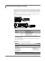
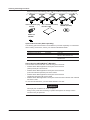
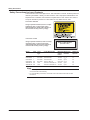

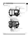
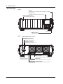
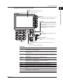
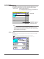
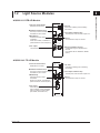
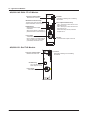
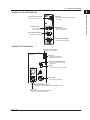
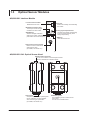
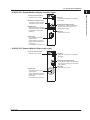
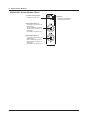
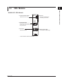
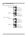
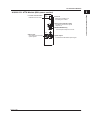
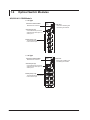
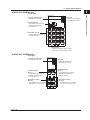
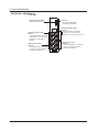

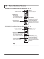
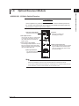

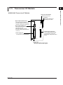
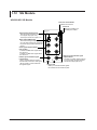

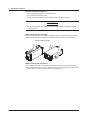
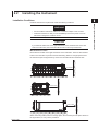
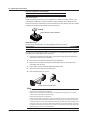
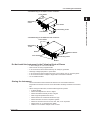
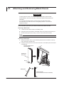
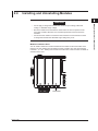
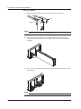
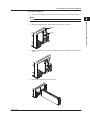
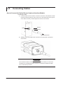
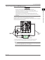
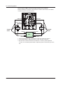
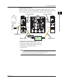
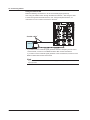
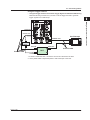
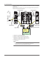
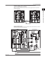
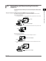
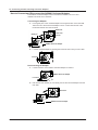
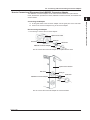
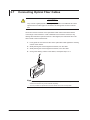
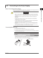
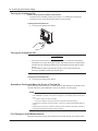


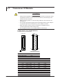

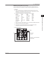
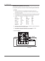
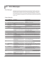
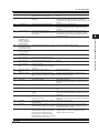


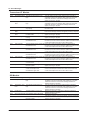
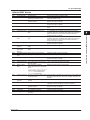
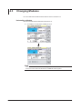
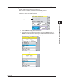
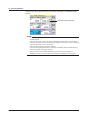
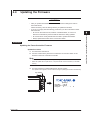
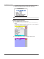
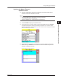
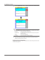
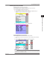
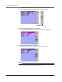
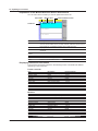
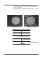
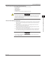
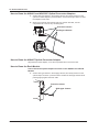
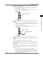


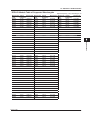
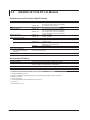
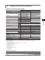
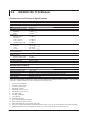


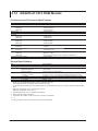
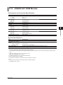
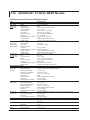
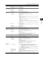

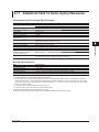
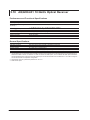
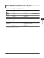
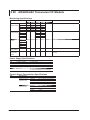
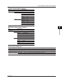
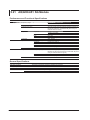
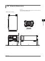
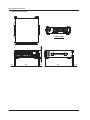
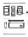
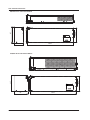

![裏-1 [更新済み]](http://vs1.manualzilla.com/store/data/006552017_2-118e1a571ce96db59df2563cbb57d6e6-150x150.png)