1
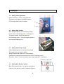
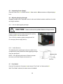
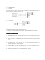
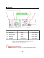
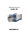
Operating Instructions
Cosmic 60R
1. Dear Customers
Thank you for purchasing Cosmic 60R Rotary Jacket Stripper.
This machine is developed for stripping various types of cables. Cutting diameter
ranges from 3.0 to 11.0mm, and quality processing is as easy as turning the
adjusting knob, with no hustle of changing blades!
Please read through and refer to this OPERATING INSTRUCTIONS as needed,
and get completely familiar with the machine and its functions for proper and safe
use.
□
On receiving the machine, please check the followings.
1)
The machine is the one you ordered.
2)
Any exterior damage done during transportation.
3)
The following accessories.
a)
Power cord with 2 phase socket
b)
Tool kit box
c)
Foot Pedal Switch
-1-
2. Safety Notes
2.1 Symbols
CAUTION
Please follow exactly the work and processes marked
with this symbol.
Failure to do so may result in
death or severe injury.
NOTE
Please follow exactly the work and processes
marked with this symbol. Failure to do so may lead to
minor injuries and to damage the machine.
2.2
Safety Requirements
CAUTION
This machine is designed for use by people over 14 year of age.
It is strictly forbidden to allow people less than 14 year of age to have
access to the machine.
The machine must only be used in dry, dust-free rooms.
Never operate the machine unless the safety cover is in place.
Always disconnect the machine from the main power supply before
carrying out any maintenance work.
Never operate the machine unless it is correctly earthed.
-2-
3. Technical Specifications
Description
Specifications
1) Cross section range
3 ~11mm outer diameter
2) Strip length
20 ~ 90 mm
3) Blade pull-back length
Max. 50mm
4) Diameter setting
Conductor Knob (Digital Display)
5) Cycle time
Max. 5 sec.
6) Blade material
Tool Steel (Carbide /Optional)
7) Controller
Micro Processor
8) Power supply
AC110V or AC230V,
9) Capacity
125VA
0 / 60 Hz
10) Machine dimensions
628 L X 241 W X 230 H
11) Machine weight
20Kg
-3-
4. Machine Overview
1. Main switch
1.
14.
15.
2.
3.
2. Digital display
3. Conductor (for diameter)
4. Adjusting knob (for Blade movement)
5. Safety cover
6. Wire guide (Leveler)
7. Fixing screw (for Leveler)
8. Foot switch connector
17.
9.
9. Bladearm
10. Blade
11. Scale (for semi-strip)
10.
8.
12. Power socket
13. Power cord
14. Centering guide
15. Length adjuster
16.
16. Rear cover
17. Select switch
12.13.
11.
5.
7.
-4-
6.
4.
5. Setting-up
5.1
Setting Cutting Diameter
Rotate Conductor3 to set cutting diameter.
The size in mm appears on Digital display2.
CW for larger and CCW for smaller.
3.
4.
5.2
Setting Strip Length
Slide Length adjuster15 to the stripping length
on the scale of Centering guide14 and tighten it.
To process cables, insert the cable end
14.
15.
into Centering guide14 to touch Length adjuster15
and it starts stripping cycle.
5.3
Setting Semi-strip Length
Rotate Adjusting knob4 to set semi-strip length.
The length in mm is read on Scale11.
Always operate this machine for semi-stripping,
otherwise the stripped-off materials will be left in Centering guide14.
Therefore, Scale11 must read shorter than Length adjuster15 at all times.
The Position to set Leveler
5.4
Setting Wire Guide (Leveler)
Slide Wire guide (leveler)6 so that the processing
cable is in line with the center in between Grippers.
-5-
5.5
Connecting Power Supply
Connect Power cord13 to Power socket12. Main switch1 ON and make sure Digital display2
is on.
5.6
Adjusting Gripping Strength
Gripping strength can be adjusted softer for thin and flexible insulation and firmer for thick
and tough insulation.
5.6.1
How to adjust gripping strength
CAUTION
Power cord must be pulled off before this procedure.
Insert a hexagon wrench (4mm) through the opening
on Rear cover16 into the shaft inside.
Turn it CCW for weaker gripping strength and CW
For stronger (See the right picture).
W
5.6.2
S
Inside Structure
The adjusting bolt is pushing the joint bar, which in turn
compresses a spring inside that makes gripping strength
(See the right figure).
NOTE : If the adjusting bolt came off when loosened
Adjusting Bolt
too much, put it back in place and screw it in.
Joint Bar
5.7
Foot Switch
Connect Foot switch to Connector8 and choose “Foot Pedal” on Select switch17.
With “Foot Pedal” selected, the start sensor is disabled.
-6-
5.8 Changing Blades
CAUTION
Main switch OFF and Power Cord must be pulled off before
this procedure.
NOTE : Read through this instruction first and be sure to understand it well.
5.8.1 Mechanism inside Bladearm
Figure (A)
Figure (B)
See figure (A). Blade and Centralizer are installed on Bladearm with a spacer in between.
Blade and the spacer are fixed-on while Centralizer can slide up and down, being pressed
downward by the lever, which is pushed upward on the other end by a spring.
Figure (B) shows when Blade is cutting into a piece of cable. Centralizer has simultaneously
slid upward, pushing the cable downward to keep it in the center of the rotor blades.
Thus Blades cut in evenly, making precision strip possible.
5.8.2 The shapes and names of each part
(1) Centralizer
(4) Fixing screw
(2) Spacer
(3) Blade
(5) Fixing washer
-7-
5.7.3 Changing Blades
1)
Removal
As shown in the figure below, loosen the fixing screw with a screwdriver and remove the 5
pieces illustrated on the previous page (5.8.2).
2)
Reassembly
Reassemble carefully though the following procedure.
□
Blades are the main wear parts in this section. Other parts seldom need replacing.
Procedure and points to care
(1)
Each Blade has two sides. Put them back in place in accordance with the figure above.
(2)
Mount Centralizer to compose a “V” shape with Blade. (See figure B on previous page,
5.8.1)
(3)
Loosely tighten the screw, and make sure that Blade, Spacer and Centralizer are
properly held inside the width of Bladearm.
(4)
Then push Blade alone with a fingertip all the way up to the end and tighten the screw.
(5)
Make sure Centralizer slides smoothly with the screw tightened.
-8-
6. Interlock
6.1 Safety Cover
With Safety cover5 removed, the circuit interlock is in effect and the machine will not
operate.
<Installation and removal of Safety Cover>
Slide Wire guide (leveler)6 all the way down when installing and removing Safety cover5.
6.2
Overload
If cables out of the specifications were processed the circuit interlock may come at work.
How to release overload interlock
CAUTION
Main switch OFF and power Cord must be pulled off
before this procedure.
Remove Rear cover16, rotate the pulley CCW to open bladearms so that the processing
cable can be taken out of Centering guide14. Connect Power cord13 and main switch1 ON.
Now interlock is released but operate 1 cycle without cable before start processing.
-9-
7. Lubrication
Lubricate the following points periodically.
1.
2.
NEVER oil Brake Plate
Lubrication points
Oil
3.
4.
Period
1.
Spline Shaft
Grease
Every 6 months
2.
Ball Screw Shaft
Grease
Every 6 months
3.
Guide Shaft
Grease
Every 6 months
4.
Slide Shaft
Lubrication oil
Every 3 months
Grease : Lithium soap type grease / viscosity 30 – 140 cst
Lubrication Oil : 32 – 100 / ISO grade
NOTE :
1)
NEVER lubricate the Brake Plates.
2)
If the interval between use is longer than 4 months, lubricate before operation.
- 10 -
8. After-Sales Service
8.1 In case of trouble please contact us or the distributor. The repair work for customers can
be difficult to do and, in many cases result in more damage to the machine. Such cases
cannot be covered by the maker warranty.
8.2 Warranty
The warranty period is 1(one) year after purchase. The followings are the circumstances in
which the warranty is invalid.
1)
Troubles caused by customers’ negligence. (accidental fall, etc.)
2)
Troubles caused by natural disaster or fire.
3)
Troubles caused by usage out of its specifications and/or intended use.
4)
Troubles caused by unauthorized repair works and/or modifications.
5)
Ware parts and replacement cost.
Manufactured by
Tamadaira 6-16-10 Hino-shi, Tokyo191-0062 Japan
Tel: +81 42-582- 7911,
- 11 -
Fax: +81 42-582-7922