1
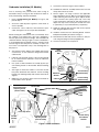
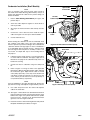
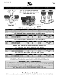
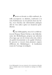
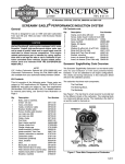
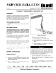
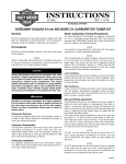
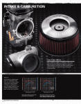
INSTRUCTIONS
®
REV. 6-8-01
-J01837
Kit Number 27454-01
S.E FLATSLIDE CARB KIT FOR SPORTSTER AND BUELL
General
1WARNING
This kit is designed for use on 1995 and later XL 1200’s and
all Twin Cylinder Carbureted Buells.
NOTE
On XL Models, you must use SCREAMIN’ EAGLE Air
Cleaner Kit (Part Number 29041-88B) with this carburetor.
On Buell Models, you must use either AIR CLEANER
RACE KIT (Part Number 91421-99Y) or AIR CLEANER
RACE KIT (Part Number 29460-96Y) with this carburetor.
Gasoline is extremely flammable and highly explosive
under certain conditions. Do not smoke or allow open
flame or sparks anywhere in the area when servicing any
part of the fuel system. Failure to comply could result in
death or serious injury.
3.
Turn fuel valve to OFF position. Disconnect fuel line at
carb and drain any remaining gas into proper container.
4.
On XL Models: Follow instructions in applicable Service
Manual and remove fuel tank.
See Service Parts Page Illustrations for kit contents.
CAUTION
Harley-Davidson motorcycles equipped with some
Screamin’ Eagle high-performance parts may not be
used on public roads and in some cases must be
restricted to closed course competition. This engine
related performance part is intended for racing applications and is not legal for sale or use in California on pollution controlled motor vehicles. Engine related performance parts are intended for the experienced rider only.
Removal of Stock Air Cleaner and
Carburetor (All Models)
NOTE
Refer to the applicable Service Manual for more detailed
instructions when removing the components referenced in
Steps 1 through 6. Service Manuals are available from your
Harley-Davidson Dealer.
1WARNING
To protect against shock and accidental start-up of
vehicle, disconnect the negative battery cable before
proceeding. Inadequate safety precautions could result
in death or serious injury.
1WARNING
Always disconnect the negative battery cable first. If the
positive cable should contact ground with the negative
cable installed, the resulting sparks may cause a battery
explosion which could result in death or serious injury.
1WARNING
Use red fuel storage container only. Storing gas in unapproved container could create a dangerous situation
such as leakage, leading to explosion or fire hazard
which could result in death or serious injury.
5.
Disconnect choke/enrichener cable from mounting
bracket on left side of bike.
6.
Remove carburetor from manifold.
7.
Disconnect throttle (Open and Close) cables at carburetor.
NOTE
This carburetor is designed to work with stock throttle cables,
so complete removal of stock cables is NOT required.
8.
Disconnect Vacuum Operated Electrical Switch (VOES).
9.
Follow instructions in applicable Service Manual and finish removing carburetor.
10. Remove choke/enrichener cable from the carburetor and
discard carburetor.
Choke
The carb in this kit uses stock choke cable and stock black
plastic nut. Obtain the new carburetor from kit. Remove black
plastic nut from kit carburetor and discard it. Remove spring
and plunger from carburetor kit and install them on the stock
choke cable and attach to kit carb. Discard stock choke
spring and plunger. Do not over tighten the plastic nut.
Choke adjustment procedures are covered at the end of
these instructions.
1.
Disconnect negative battery cable first followed by positive cable.
11. On XL models, perform hose modifications described on
the following page.
2.
Remove stock air cleaner assembly including backplate.
NOTE
If your installation is for Buell, proceed to Page 4.
-J01837
1 of 9
XL Models Only
Fuel and Vacuum Hose Modification
NOTE
On XL Models, the Fuel hose and Vacuum Hose must be
modified prior to installing to the new carburetor. Perform the
following procedures.
1.
2.
See Figure 1. Locate and remove the fuel hose from the
fuel petcock. Lay the hose on a flat surface and trim 1/2
inch to 5/8 inch of the hose from the end of the bend.
Obtain one of the Hose Clamps from kit and using
clamp, reinstall end of hose trimmed in previous Step to
fuel petcock. Tighten securely.
i03953
End of Hose To
Fuel Petcock
Trim 1/2 inch to 5/8 inch
from End
To Carburetor
Figure 1. Trim Fuel Hose At Petcock End
i03954
To Fuel Petcock
Short Hose to
V.O.E.S.
3.
See Figure 2. Note that Figure 2 represents the current
Vacuum hose configuration. The heat shield is installed
to Fuel Petcock hose, the short hose routes to V.O.E.S.,
and the long hose routes to carburetor.
Plastic
Manifold
Heat Shield
(Installed on Fuel
Petcock Hose)
To
Carburetor
Vacuum
Fitting
Figure 2. Original Vacuum Hose Configuration
i03955
4.
See Figure 3. This is the Modified Hose Configuration.
Note the following:
Fuel Petcock Hose
Trimmed 2 inches
The heat shield from the petcock hose has been
removed and petcock hose has been shortened by 2
inches.
New 5-1/4 inch
Hose routed
to Carburetor
Vacuum
Fitting
See Figure 3. Obtain heat shield for V.O.E.S. (provided
in kit) and install. The V.O.E.S. hose will route behind
horn on the left side to the V.O.E.S. vacuum fittting.
The Short hose (old V.O.E.S.) has been removed and
replaced by a longer (5-1/4 inch) hose cut from 9 inch
hose supplied with new carb. Heat Shield from kit is then
installed. This hose will route to the vacuum fitting on
carburetor.
Hose to V.O.E.S
Installed behind Horn
on Left Side
Heat Shield
For V.O.E.S
From Kit
Figure 3. Modified Vacuum Hose Configuration
-J01837
2 of 9
Carburetor Installation (XL Models)
9.
NOTE
Prior to installing carb, perform initial cable routing as
described in Step 1 on Page 5. This will allow the cables to
be in position during carburetor installation.
Connect hose shown in Figure 3 to the V.O.E.S.
10. Sandwich the V.O.E.S. assembly between the horn and
the top motor mount as shown.
1.
Refer to Cable Routing (XL Models) on Page 5, and
perform Step 1.
2.
Screw the cable adjusters together to make them as
short as possible.
11. Refer to Figure 4 on Page 3. Refer to the applicable
Harley-Davidson Service Manual and adjust throttle
cables following the instructions given. Adjust throttle
cable so throttle valve (slide) opens fully. Lever stop
screw should touch carb body at wide open throttle. To
adjust lever stop screw, loosen jam nut and turn screw
in (clockwise) or out (counterclockwise), respectively.
3.
Connect the “close” cable first, then install the “open”
cable. See Figure 4 for close-up of cable installation.
12. Adjust the opening cable until the slide can be opened
fully. Snug the adjuster lock nut.
NOTE
Before inserting the carburetor into the stock manifold, check
the condition of the rubber seal. If the seal is damaged, it
must be replaced to prevent air leakage. The fit between the
carburetor and the seal ring is tight. For ease of installation it
is recommended that the mating surfaces, carburetor body
and seal ring be lubricated prior to assembly to reduce surface friction. Use liquid dish soap or tire mounting lube for
this purpose.
13. Install the choke to the horn mounting bracket. Perform
Backplate Installation procedures on Page 6.
14. Reinstall the fuel tank and connect fuel hose to fuel petcock using remaining new clamp supplied in kit.
15. Connect vacuum hose to fuel petcock.
i03915
4.
See Figures 3 and 4. Slip the new V.O.E.S./fuel petcock
vacuum hose on the carburetor fitting below throttle
cable bracket.
5.
Lubricate only the inside surface of the seal ring that will
be in contact with the carburetor. Insert the carburetor
into the manifold.
6.
Use a pick or small screwdriver to carefully pry the special retaining washer off the V.O.E.S. Discard retaining
washer.
7.
See Figure 5. Rotate the V.O.E.S. so that the vacuum
line points downward. Note V.O.E.S. and its mounting
bracket have indexing bumps and notches that must be
aligned.
8.
Obtain the new retention washer from kit and install to
retain V.O.E.S. in this position.
Horn
Mounting
Bolt
Top Motor Mount
Vacuum Fitting
(Old Position)
Retention
Washer
V.O.E.S.
Notch
Vacuum Fitting
(New Position)
Figure 5. V.O.E.S. Installation
i03916
Accelerator Pump
Adjusting Screw
(End of stroke)
Close Cable
Open Cable
Close
Cable
Lever Stop Screw
Jam Nut
(hidden)
Accelerator Pump
Adjusting Screw
(Start of stroke)
Vacuum Fitting
V.O.E.S/Fuel
Petcock
Figure 4. Cable Installation
-J01837
3 of 9
Carburetor Installation (Buell Models)
NOTE
Prior to installing carb, perform initial cable routing as
described under Cable Routing (Buell Models) Step 1 on
Page 5. This will allow the cables to be in position during carburetor installation.
1.
Refer to Cable Routing (Buell Models) on Page 5, and
perform Step 1.
2.
Screw the cable adjusters together to make them as
short as possible.
3.
See Figure 6. Remove throttle cable clamps and discard.
4.
Connect the “close” cable first, then install the “open”
cable. See Figure 4 for close-up of cable installation.
5.
Connect V.O.E.S. hose.
NOTE
Before inserting the carburetor into the stock manifold, check
the condition of the rubber seal. If the seal is damaged, it
must be replaced to prevent air leakage. The fit between the
carburetor and the seal ring is tight. For ease of installation it
is recommended that the mating surfaces, carburetor body
and seal ring be lubricated prior to assembly to reduce surface friction. Use liquid dish soap or tire mounting lube for
this purpose.
6.
Lubricate only the inside surface of seal ring that will be
in contact with the carburetor. Also apply a light coat of
lubricant to the spigot of the carburetor body. Push carburetor into seal ring.
7.
Connect fuel hose to carburetor using new clamp from
kit.
8.
Refer to Figure 4 on Page 3. Refer to the applicable
Buell Service Manual and adjust throttle cables following
the instructions given. Adjust throttle cable so throttle
valve (slide) opens fully. Lever stop screw should touch
carb body at wide open throttle. To adjust lever stop
screw, loosen jam nut and turn screw in (clockwise) or
out (counterclockwise), respectively.
NOTE
Turn the handlebar to the right and adjust the throttle freeplay with the closing cable adjuster to approximately 1/8 inch.
9.
i03956
Open Cable
Close Cable
Screw
Throttle
Cable Clamps
Idle Adjuster
Cable
Figure 6. Throttle Cable Installation (Buell)
i03957
Drain Hose
Figure 7. Routing Drain Hose (Buell)
Use cable strap and secure the remote idle adjuster
cable to the frame tube.
10. See Figure 7. Route drain hose downward from drain fitting and continue towards rear wheel through the space
between the engine rear cylinder and both rear cylinder
push rod covers. Continue route downward between
gearcase cover and engine crankcase.
11. Install the choke to choke mounting bracket and perform
Backplate Installation procedures on Page 6.
-J01837
4 of 9
Cable Routing (XL Models)
Cable Routing (Buell Models)
1WARNING
1WARNING
When installing cables to the new carburetor make certain that cables are well lubricated and do not bind when
handlebars are turned from lock to lock. Improperly
installed throttle cables can affect vehicle operation
which could result in death or serious injury.
When installing cables to the new carburetor make certain that cables are well lubricated and do not bind when
handlebars are turned from lock to lock. Improperly
installed throttle cables can affect vehicle operation
which could result in death or serious injury.
1.
1.
See Figure 8. Route the throttle cables with large radius
curves so that they do not interfere with other components.
i03914
See Figure 9. Route the throttle cables with large radius
curves so that they do not interfere with other components.
i03958
Throttle Cables
Fork
Tube
Route Cables
Between
Cylinder
Head and
Top Motor
Mount
Brake Hose
Route
Cables
Between
Fork Tube
and Brake
Hose
Larger
Radius
Figure 9. Throttle Cable Routing (Buell Models)
Figure 8. Throttle Cable Routing (XL Models)
-J01837
5 of 9
Attaching Adapter To Backplate
(XL Models)
Choke Adjustment
i01746
CAUTION
In the next step, do not use the stock screws from backplate assembly. The screws are too long and will prevent
O-ring sealing interface between adapter and carb.
1.
See Service Parts Illustration on Page 7. Insert the large
diameter O-ring into the adapter. While “sandwiching the
gasket between the adapter and backplate assembly,
attach the adapter to the backplate assembly with the
screws from SCREAMIN’ EAGLE air cleaner kit. Apply 1
or 2 drops of Loctite 243 (blue) on each of the screws.
CAUTION
Before attaching backplate to cylinder heads, check that
carb is fully inserted into the manifold. If the carb is not
fully seated, air leaks might result.
2.
See Service Parts Illustration on Page 7. Refer to
Instruction Sheet covering SCREAMIN’ EAGLE air
cleaner kit and follow instructions given to install air
cleaner assembly.
Attaching Adapter To Backplate
(Buell Models)
CAUTION
Figure 10. Proper Choke Cable Free Play
Starting
Pull choke out fully, leave throttle closed and crank engine
with starter. Push choke knob in as engine warms up and
engine runs smoothly.
RECOMMENDED TUNING PROCEDURES
This carburetor is tuned to run well on a majority of HarleyDavidson/Buell engine configurations however, if fine tuning
is required for a particular engine configuration, follow the
procedures in the tuning instructions supplied with with this
kit.
In the next step, Do NOT use the screws from Race Air
Cleaner Kits (Part Numbers 91421-99Y and 29460-96Y) to
install the adapter. The screws are too long and will prevent O-ring sealing interface between adapter and carb.
CAUTION
Check that carb is fully inserted into the manifold. If the
carb is not fully seated, air leaks might result.
1.
See Service Parts Illustration on Page 7. Insert the large
diameter O-ring into the adapter and install the adapter
onto the front of the carburetor.
2.
Install the Air Cleaner support bracket to the cylinder
heads.
3.
Attach the backplate assembly to the adapter using 1/420x1/4 inch screws or the stock (original) backplate
assembly screws.
4.
See Service Parts Illustration on Page 7. Refer to
Instruction Sheet covering Buell AIR CLEANER RACE
KITS and follow instructions given to install air cleaner
assembly.
-J01837
6 of 9
®
Kit No. 27454-01
Service Parts
Date 6/01
42mm Flatslide Carb Kit
i03918
i03952
1
Buell Fitment
XL Fitment
3
2
NOTE
Gasket Shown
for Illustration
Purposes Only
(Not Included)
NOTE
Gasket Shown
for Illustration
Purposes Only
(Not Included)
Screws From Screamin’
Eagle Air Cleaner Kit
(Part Number 29041-88B)
Kit Number 27454-01
Item Description
1
Carb Assembly
2
Adapter
3
O-ring
4
Main jet #155(not shown)
5
Main jet #165(not shown)
-J01837
Part Number
not sold
27756-98
27754-98
27910-98
27914-98
Item
6
7
8
9
Use 1/4-20x1-1/4 inch or
stock (original) Backplate
Assembly Screws.
Do Not use screws from
Race Air Cleaner Kits
(Part Numbers 91421-99Y
and 29461-96Y)
Description
Part Number
Hose clamp (2) (not shown) not sold
Cable tie (3)(not shown)
27753-98
Washer, retention (not shown) 11192
Hose, vacuum (3/16x5-1/4 inch)
(not shown)
not sold
7 of 9
®
Kit No. 29565-98
Service Parts
Date 6/01
42mm Carb Rebuild Kit
i01749.tiff
1
2
3
4
5
6
13
7
15
17 18
16
19
14
10 9
20
8
11
22
21
37
23
41
12
42
38
20
39
40
43
44
45
53
24
25
48
29
46
47
54
35
32
51
36
55
60
52
56
61
34
65
64
63
33
79
66
80
59.a
67
59
31
62
57
58
27
28
49
50
26
30
69
81
68
82
70
71
72
73
74
75
NOTE
See next page for index identification and
description. Service Parts have a HarleyDavidson Part No. listed.
76
77
78
-J01837
8 of 9
®
Item
1
2
3
4*
5*
6*
7
8
9
10
11
12
13
14
15
16
17
18
19
20
21
22
23
24
25
26
27
28
29
30
31
32
33
34
35
36
37
38
39
40
41
42
43
Service Parts
Description
Screw, top cover (flat head)
Screw, top cover
Top cover
Gasket, top cover
E-ring, jet needle
Washer, needle clip
Jet needle (4 sizes available)
Lever, throttle valve
E-ring
Packing link lever
Pin, link lever
Throttle valve
Screw, needle retaining clip
Clip, needle retainer
Sealing ring, throttle valve
Seal, throttle valve
Pulley, cable bracket
E-ring, cable bracket
Bracket ass’y. cable
Bolt
Spacer
Plate, lock tab
Screw
Guide holder, starter
Spring, starter plunger
Starter plunger
Body ass’y, bearing and spigot (N/A)
Seal, spigot body
Ring (Steel)
Lever, accelerator pump
Pin, throttle lever
Lever, throttle
Spring, accelerator pump adjuster
Screw, accelerator pump adjuster
Spring, accelerator pump return
Mixing body ass’y (N/A)
Packing, shaft (plastic)
Adjusting screw, accelerator pump
O-ring, accelerator pump screw
Plate, lock tab for shaft
Pin, throttle stop lever
Lever, throttle stop
Adjusting screw, throttle
Part No.
27768-98
27761-98
27760-98
Item
44
45
46
47
48
49
50
51
52*
53
54*
55
56
57
58
59
59a
60
61
62
63*
64
65
66
67*
68*
69*
70
71
72
73*
74
75
76*
77
78*
79
80*
81
82
Kit No. 27454-01
Date 6/01
42mm Carb Rebuild kit
Description
Part No.
Nut, throttle stop
Spring, throttle return
Shaft, throttle
Plate, fuel joint retainer
Screw, fuel joint retainer
Screw, pilot air adjusting
Spring, pilot air screw
Washer, pilot air screw
O-ring, pilot air screw
27765-98
Fuel joint
O-ring, fuel joint
27771-98
Packing, idle adjuster
Washer, idle adjuster (Steel)
Spring, idle adjuster
Ring, idle adjuster (Brass)
Idle adjuster ass’y (Long)
Idle adjuster screw (Short)
Air jet (Blank)
Needle jet (723 Series)
Nozzle, accelerator pump
O-ring, accelerator pump
27764-98
Pilot jet
Extender, main jet
Main jet
O-ring, needle valve
27757-98
Screw w/washer, needle valve retainer 27769-98
Needle valve ass’y w/O-ring
27759-98
Float assembly
Pin, float
Screw, float pin
Packing, float bowl
27758-98
Float chamber body
Hose, overflow
O-ring, drain plug
27770-98
Drain plug
Screw, float bowl (4)
27763-98
Rod, accelerator pump
Boot, accelerator pump rod
27766-98
Plunger, accelerator pump
Spring, accelerator pump
NOTE
Items shown in “bold” and with asterisk (*) are included in Carburetor Rebuild Kit P/N 29565-98.
-J01837
9 of 9