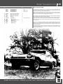
1
42
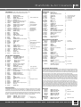
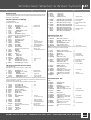
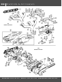
114 Manifolds & Air Cleaners
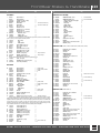
1275
Manifolds & Air Cleaners
1500
Manifolds & Air Cleaners
BRADFORD 01274 735 537 . BRISTOL 0117 923 2523 . DARLINGTON 01325 281 343
Manifolds & Air Cleaners 115
ill. Part Number
No
Description
Qty.
Req.
Details
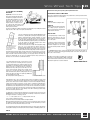
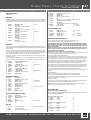
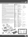
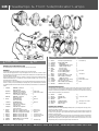
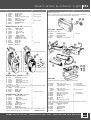
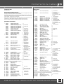
1275 Manifolds (all G-AN4, G-AN5, H-AN9, H-AN10 and A-AN10 models)
See also 'Performance & Tuning' in Accessories for Performance Parts.
1
2
3
4
10
AJM601
GHF261
GHF301
12A1211
12G583
GASKET, manifolds
NUT, brass (manifolds to head)
WASHER, plain
WASHER, manifolds to head
MANIFOLD, inlet*
1
6
2
4
1
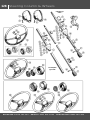
12H1405
1B3664
12G609
SH504051
GHF331
12G1450
ADAPTOR, breather control valve
WASHER, sealing
BRACKET, breather control valve
SCREW, bracket to manifold
WASHER, locking
MANIFOLD, inlet*
(*less tapped boss for closed circuit breather control valve)
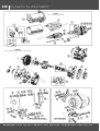
21
22
25
26
27
28
29
30
35
36
37
40
41
42
45
50
51
52
53
54
55
53K1452
2K4954B
AEA635
ADP210
1B3664
CHS2620
GHF202
GHF333
SH504041
GHF331
GHF300
TE504081
GHF200
GHF331
12G297
12G420
12G1581
53K507
GHF261
12A1211
GHF332
SCREW, blanking
WASHER, sealing
CORE PLUG
PLUG, threaded
WASHER, sealing
STUD (carburettor mounting)
NUT
WASHER, locking
SCREW (heater pipe clip to inlet manifold)
WASHER, locking
WASHER, plain
STUD
NUT
WASHER, locking
SLEEVE (inlet manifold to head)
MANIFOLD, exhaust
MANIFOLD, exhaust
STUD (exhaust manifold to down pipe)
NUT, brass
WASHER, plain
WASHER, locking
1
1
1
1
1
1
exhaust manifold to head
{
|
|
|
}
{
|
1 |
1 }
2
1
1
4
4
4
1 {
1 |
1 }
1 {
1 |
1 }
2
1
1
3
3
3
3
all 12CC; to
12CE/Da/H3200;
from 12CE/Da/H3301
to 12CE/Da/H3400.
12CE/Da/H3201 to
12CE/Da/H3300;
12CE/Da/H3400 on;
all 12V units.
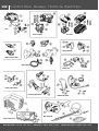
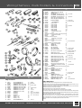
76
77
AHA8419
AHA8420
GFE1004
BH505361
GHF332
GHF301
ACA8014
GHF222
PWZ205
12G485
12G1460
1G2624
AIR CLEANER ASSEMBLY, front
AIR CLEANER ASSEMBLY, rear
ELEMENT, air cleaner
BOLT (air cleaner to carburettor)
WASHER, locking
WASHER, plain
GASKET (air cleaner to carburettor)
NUT, nyloc (air cleaner straps)
WASHER, plain
HEATSHIELD, carburettors
HEATSHIELD, carburettors
GASKET*
1
1
2
4
4
4
2
1
1
1
1
6
heater pipe clip to inlet manifold
12CC/Da/H3629 on;
all 12CE and 12V.
all G-AN4; up to G-AN5-139772
G-AN5-139773 on.
AEA586
AEG557
AEG558
SH604051
GHF200
GHF331
SH604071
GHF200
GHF331
GHF300
BH605151
GHF222
GHF301
INSULATING BLOCK
BRACKET, heatshield, front
BRACKET, heatshield, rear
SCREW, bracket to heatshield
NUT
WASHER, locking
SCREW (front bracket to timing cover)
NUT
WASHER, locking
WASHER, plain
BOLT (rear bracket to engine back plate)
NUT, nyloc
WASHER, plain
2
1
1
2
2
2
1
1
1
1
1
1
1
to Dec approx.1967
from approx. Dec 1967
{
|
|
|
|
|
|
| from approx. Dec 1967
|
|
|
|
}
Under Bonnet Decals
In many sections of this catalogue may be found information on engraved or printed plates and decals applied
to components and cars when they were manufactured. As a delightful finishing touch to a painstaking
restoration they are unsurpassed; much research has been put in by the people who now reproduce these items
to ensure total accuracy. With MG & Austin Healey being amongst the most comprehensively served marques in
the classic car parts market place, just about every decal or plate your car was fitted with has now been
reproduced - for example, the 'Coopers' transfers and decals for 1275 air cleaner assemblies.
CRTR202A
CRTR202B
CRST119
TRANSFER, 'Coopers', front air box
TRANSFER, 'Coopers', rear air box
DECAL, 'Unipart' (both air boxes)
101
102
103
104
105
106
107
108
110
111
112
113
114
120
121
122
123
124
125
126
127
128
AJM681
DS2512
058258
WP20X
100498
137845
WP20X
CHA360
RKC723
122132
WF513
SH505101
GHF332
CHA256
WF8
BH505131
GHF106
GEG742
GHF333
CHA471
ADP212
AEC699
130 TKC1570
RKC4165
131 141648
132 12G2125
133 GFE1063
134 GHF332
135 BH505181
136 623313
626960
137 SH604041
138 GHF331
139 GHF300
140 616014
141 PCR2409
142 BHH1719
143 GHF331
144 GHF300
145 CHA501
146 UKC2992
UKC8372
(*manifold to heatshield and heatshield to insulating block & insulating block to carburettor)
78
80
81
82
83
84
85
86
87
88
89
90
91
Qty.
Req.
Details
GASKET, manifolds
ROLL PIN (locating inlet manifold)
CLAMP, small
WASHER, plain
NUT
CLAMP, large
WASHER, plain
NUT
MANIFOLD, inlet
BLANKING PLUG
WASHER, fibre
SCREW (carb & heat shield to manifold)
WASHER, locking
MANIFOLD, exhaust
WASHER, locking
BOLT (exh manifold to inlet manifold)
BOLT (exh manifold to down pipe)
GASKET (manifold to down pipe)
WASHER, locking
NUT, special
PLUG, exhaust manifold
WASHER, sealing
1
2
4
6
6
2
2
2
1
1
1
4
4
1
2
2
3
1
3
3
1
1
{
}
{
|
}
on upper mounting studs
on upper & lower outer
mounting studs
on lower inner
mounting studs
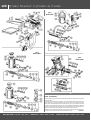
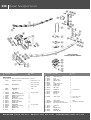
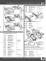
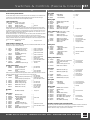
1500 Air Cleaners and Heat Shields
to 12CC/Da/H3628.
1275 Air Cleaners & Heat Shields
60
61
62
63
64
65
66
67
69
Description
1500 Manifolds (all G-AN6 models)
(*with tapped boss for closed circuit breather control valve)
11
12
13
14
15
20
ill. Part Number
No
1 {
1 } to approx. 1971
2
from approx. 1971
AIR BOX ASSEMBLY, 'Rover Triumph'
AIR BOX ASSEMBLY, 'BL Cars'
SEAL, back plate
GASKET
AIR FILTER
WASHER, locking
BOLT (air box to carburettors)
CLIP (Pipe)
CLIP (Pipe)
SCREW
WASHER, locking
WASHER, plain
AIR HOSE (23.5" long)
CLIP, hose to front panel
SCREW (hose clips to front panel platform)
WASHER, locking
WASHER, plain
HEATSHIELD, carburettors
GASKET*
1
1
1
4
2
4
4
1
1
1
1
1
2
2
1
1
1
1
4
to late 1978
from late 1978
for 'Rover Triumph' air box
for 'BL Cars' air box
{
|
| from approx. 1976
|
}
{
| to mid 1977
(*carb to heatshield & heatshield to manifold)
}
HEATSHIELD, carburettors
1 { from mid 1977
(does not require gaskets)
}
Using Sports Air Filters & Exhausts
In the Accessories section you will find K&N Sports air filters & Sports Exhausts that are intended to provide easy,
cost effective improvements to the performance of your car. The accent is on 'intended', because on a large
number of vehicles so fitted, the only positive improvement is to the appearance of the engine bay. In fact, if the
knock on effects of these potentially more efficient parts have not been recognised and the appropriate steps
taken, the result may be a car which doesn't 'go any faster' but uses more fuel and runs badly.
As any engine tuning guru will relate, the majority of modifications are based around the principle of increasing
power by getting better gas flow through the engine; more fuel/air charge enters, while the exhaust gases can
leave more easily, creating a better 'scavenge' effect to help to draw the new charge into the cylinders. Given
better than standard gas flow through the use of (say) K&N air filters and maybe a tubular exhaust manifold, the
carburettors will need tweaking to ensure that the fuel/air ratio of the charge remains correct. Potentially
increased air flow into the system results in a need for a corresponding increase in fuel, otherwise the engine
will run lean (causing poor economy, rough running or more detrimental effects on the pistons & valves).
In order to increase the fuel flow to match the air flow, simply winding down the jet nut on the carburettor by a
few flats is usually not sufficient. A change of carburettor needle to one with a richer profile is required; only
then can the fine adjustment be carried out on the carburettor to find its optimum setting. Suggestions for nonstandard carburettor needles are given here (needles are sold individually, by the way, plus you will need to know
on 1275cc cars whether your carburettors use fixed or biased/sprung needles). If you wish to experiment, the
needle chart booklet (ALT9001), detailing the full range of SU needles and their profiles, would be very useful.
1275 models
AUD1242
CUD1012
AUD1242
CUD1014
CUD1014
ALT9001
NEEDLE, fixed type H6
NEEDLE, biased type AAN
NEEDLE, fixed type H6
NEEDLE, biased type AAQ
NEEDLE, biased type AAQ
BOOKLET, needle chart
2
2
2
2
2
a/r
{ K&N filters
}
{ K&N filters & exhaust
}
NEEDLE, biased, type AAM
BOOKLET, needle chart
2
a/r
K&N filters & exhaust
K&N filters
1500 Models
CUD1011
ALT9001
DERBY 01332 756 056 . LONDON 020 8867 2020 . MANCHESTER 0161 480 6402
44
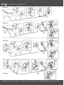
116 Exhaust System
Type 1 Exhaust
Type 2 Exhaust
Type 3 Exhaust
Type 4 Exhaust
BRADFORD 01274 735 537 . BRISTOL 0117 923 2523 . DARLINGTON 01325 281 343
Exhaust System 117
ill. Part Number
No
Description
Qty.
Req.
Details
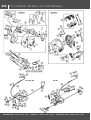
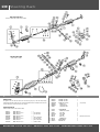
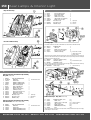
Type 1: 1275 'Single Box' System.
RHD Specification, 1967-69 (G-AN4; H-AN9)
UK cars used a 'single box' system with flared front pipe from 1967 to 1969 inclusive. However, a few cars in
this period had the 'cross box' (Type 2) system, particularly near the end of 1969.
1
2
3
4
5
6
7
8
9
10
11
12
13
14
15
16
17
18
19
20
21
22
GEX1306
GEX3365
GEX7153
GEX7154
HMP815003
GEX7049
GEX7072
GEX7073
GEX7074
GEX7155
GEX7250
GEX7151
GEX7152
SH605071
SH605101
SH605121
SH604071
GHF332
GHF331
PWZ205
GHF201
GHF200
GHF222
FRONT PIPE
SILENCER
BRACKET, gearbox
STRAP, bracket to front pipe
FITTING KIT, type 1 system
CLAMP, manifold to front pipe
CLAMP, front pipe to strap
CLAMP, intermediate mounting
CLAMP, system joint
MOUNTING, intermediate
WASHER, insulation
BUSH, rubber
DISTANCE TUBE
SCREW (5/16" UNF x 7/8")
SCREW (5/16" UNF x 1 1/4")
SCREW (5/16" UNF x 1 1/2")
SCREW (1/4" UNF x 7/8")
WASHER, locking (5/16")
WASHER, locking (1/4")
WASHER, plain (5/16")
NUT (5/16" UNF)
NUT (1/4" UNF)
NUT, nyloc (5/16" UNF)
1
1
1
1
1
1
1
1
1
1
2
2
1
4
1
1
1
5
1
3
3
1
2
Non-North American LHD Specification, 1967-72 (G-AN4; up to G-AN5-139136; H-AN9)
RH Steering Specification, 1970-72 (G-AN5-74886 to 139136; H-AN10; A-AN10).
The 'cross box' system with flared front pipe to manifold joint was used on European cars between '67 and '72
inclusive (only Midgets from '70; Sprite exports ceased in '69). It was used on UK cars from '70 to '72.
36
37
38
39
40
41
42
43
44
45
46
47
48
49
50
51
52
53
54
55
56
GEX1306
GEX3369
GEX7153
GEX7154
GEX7168
GEX7169
GEX7364
GEX7365
SH605051
GHF332
HMP815004
GEX7049
GEX7072
GEX7073
GEX7074
GEX7170
GEX7155
GEX7250
GEX7151
GEX7152
SH605071
SH605101
SH605121
SH604071
GHF332
GHF331
PWZ205
GHF201
GHF200
GHF222
FRONT PIPE
RESONATOR & SILENCER
BRACKET, gearbox
STRAP, bracket to front pipe
BRACKET, LH rear mtg. to boot floor
BRACKET, RH rear mtg. to boot floor
BRACKET, LH rear mtg. to boot floor
BRACKET, RH rear mtg. to boot floor
SCREW, brackets to boot floor
WASHER, locking
FITTING KIT (type 2 system)
CLAMP (manifold to front pipe)
CLAMP
CLAMP (intermediate mounting)
CLAMP (system joint)
CLAMP (pipe to RH rear mounting)
MOUNTING (intermediate/LH rear)
WASHER, insulation
BUSH, rubber
DISTANCE TUBE
SCREW (5/16" UNF x 7/8")
SCREW (5/16" UNF x 1 1/4")
SCREW (5/16" UNF x 1 1/2")
SCREW (1/4" UNF x 7/8")
WASHER, locking (5/16")
WASHER, locking (/4")
WASHER, plain (5/16")
NUT (5/16" UNF)
NUT (1/4" UNF)
NUT, nyloc (5/16" UNF)
1
1
1
1
1
1
1
1
4
4
1
1
2
1
1
1
2
4
2
1
7
1
2
1
9
1
4
7
1
2
{
}
{
}
G-AN4; to G-AN5-138800;
H-AN9; H-AN10; A-AN10.
G-AN5-138801
& future
pipe to strap/LH rear mounting
Type 3: 1275 'Cross Box' System
RHD and Non-North American LHD Specification, 1973-74 (G-AN5-139137 on).
This cross box system, only fitted to Midgets, used a three stud flanged manifold joint on the front pipe. Type 3
is available as a one piece exhaust system as well as components.
GEX142
EXHAUST ASSEMBLY
1
one piece system
61
62
63
64
65
66
67
GEX1307
GEX3369
ARH1806
GEX7153
GEX7154
GEX7364
GEX7365
FRONT PIPE
RESONATOR & SILENCER
FLANGE, front pipe
BRACKET, gearbox
STRAP (bracket to front pipe)
BRACKET, LH
BRACKET, RH
Description
Qty.
Req.
68
69
SCREW, brackets to boot floor
WASHER, locking
FITTING KIT, type 3 system
OLIVE (front pipe to manifold)
CLAMP
CLAMP (intermediate mounting
CLAMP (system joint
CLAMP (pipe to RH rear mounting
MOUNTING (intermediate/LH rear
WASHER, insulation
BUSH, rubber
DISTANCE TUBE
STUD, manifold
SCREW (5/16" UNF x 7/8")
SCREW ( 5/16" UNF x 11/4")
SCREW (5/16" UNF x 11/2")
SCREW (1/4" UNF x 7/8")
WASHER, locking (5/16")
WASHER, locking (1/4")
WASHER, special (manifold stud)
WASHER, plain (5/16")
NUT (5/16" UNF)
NUT (1/4" UNF)
NUT, nyloc (5/16" UNF)
NUT, brass
4
4
1
1
2
1
1
1
2
4
2
1
3
7
1
2
1
12
1
3
4
7
1
2
3
70
71
72
73
74
75
76
77
78
79
80
81
82
83
84
85
86
87
88
89
90
91
SH605051
GHF332
HMP815005
GEX7193
GEX7072
GEX7073
GEX7074
GEX7170
GEX7155
GEX7250
GEX7151
GEX7152
53K507
SH605071
SH605101
SH605121
SH604071
GHF332
GHF331
12A1211
PWZ205
GHF201
GHF200
GHF222
GHF261
Details
pipe to strap/LH rear mounting
Type 4: 1500 'Cross Box' System.
Type 2: 1275 'Cross Box' System.
30
31
32
33
34
35
ill. Part Number
No
1
1
1
1
1
1 { rear mounting
1 } to boot floor
RHD Specification, 1975-79 (G-AN6).
Minor changes occurred on the rear part of the system at G-AN6-200001 and the silencer mounting changed
at G-AN6-169792 (note that there is a choice of fitting kits).
100 GEX1618
101 GEX164
GEX175
102 GEX7364
103 GEX7365
104 SH605051
105 GHF332
HMP815006
HMP815007
106
107
108
109
110
111
112
113
114
115
116
117
118
119
120
121
122
123
124
125
126
127
128
129
130
131
GEG742
GEX7470
GEX7073
GEX7072
GEX7170
GEX7468
GEX7155
GEX7250
GEX7151
GEX7152
GEX7251
CHA364
GHF106
BH605151
SH605071
SH605121
SH604071
GHF333
GHF332
GHF331
PWZ205
CHA471
AHH8382
GHF201
GHF200
GHF222
DOWN PIPE
REAR PIPE (with resonator & silencer)
REAR PIPE (with resonator & silencer)
BRACKET, LH rear mtg. to boot floor
BRACKET, RH rear mtg. to boot floor
SCREW (bracket to boot floor)
WASHER, locking
FITTING KIT, type 4 system
(includes items marked *)
FITTING KIT, type 4 system
1
1
to G-AN6-200000.
1
from G-AN6-200001
1
1
to G-AN6-169791
4/2 { Qty. decreases from
4/2 } G-AN6-169792 on.
1 { to G-AN6-169791
}
1 { from G-AN6-169792
(includes items marked †)
}
GASKET *†, manifold to down pipe
1
OLIVE *†, down pipe to rear pipe
1
CLAMP *†, intermediate mounting
1
CLAMP *†, pipe to LH rear mounting
1
CLAMP *, pipe to RH rear mounting
1
CLAMP †, pipe to RH rear mounting
1
MOUNTING *†, intermediate/LH rear
2
WASHER *†, insulation
3/5
* uses 3; † uses 5.
BUSH *, rubber
2
DISTANCE TUBE *
1
MOUNTING †, RH (clamp to boot floor)
1
SPACER *†
1
BOLT *†, (3/8" UNF x 11/2")
3
BOLT *†, (5/16" UNF x 17/8")
4
SCREW *†, (5/16" UNF x 3/4")
5
SCREW *†, (5/16" UNF x 11/2)"
1
SCREW *†, (1/4" UNF x 7/8")
1
WASHER *†, (locking, 3/8")
3
WASHER *†, (locking, 5/16")
9
WASHER *†, (locking, 1/4")
1
WASHER *†, (plain)
3
NUT *†, (special)
3 { manifold to
NUT *†, (special)
3 } down pipe
NUT *†, (5/16" UNF)
4
NUT *†, (1/4" UNF)
1
NUT *†, nyloc (5/16" UNF)
2
Investing For The Future
If, like most classic car owners, you insist on carefully fitting your own exhaust instead of paying the local
exhaust centre to throw it nonchalantly under the car for you, remember three little details.
Use a dab of exhaust assembly paste on each of the system joints, and smear a little anti-seize compound on
the threads of all nuts and bolts, leaving them all a bit loose until you're sure the system is in exactly the right
place. In fact, the second recommendation is valid for all nuts & bolts fitted on the car: suspension, steering or
whatever (just don't get grease on the brake surfaces, that's all!). You will appreciate it when you're lying on
your back on the cold garage floor trying to undo them, some time in the future.
DERBY 01332 756 056 . LONDON 020 8867 2020 . MANCHESTER 0161 480 6402
46
118 Road Wheels & Tools
ill. Part Number
No
Description
Qty.
Req.
Details
Road Wheels & Tools
See also 'Exterior Trim' in Accessories for Sports Road Wheels.
Steel Road Wheel, Standard Equipment 1967-1969
(G-AN4; H-AN9)
71
72
73
74
75
AHA6455
24A1032
88G322
AHA5660
2A8055
ROAD WHEEL, steel (3.5" x 13")
CLAMP (spare wheel to boot floor)
NUT, wheel
HUB CAP ('embellisher'), plain
HUB CAP ('embellisher'), 'AH' motif
5
1
16
4 G-AN4.
4 H-AN9.
Steel Road Wheel, Standard Equipment 1970 on
(G-AN5; G-AN6; H-AN10; A-AN10)
80
81
82
83
84
85
AHA8892
AHA8914
AHA9881
AHA9940
AHA8785
AHA8785SS
AHA8950
WHEEL, steel, 'Rostyle' (4.5J x 13")
CLAMP, spare wheel to boot floor
WHEEL, steel, 'Rostyle' (4.5J x 13")
CLAMP (spare wheel to boot floor)
NUT, wheel
NUT, wheel
CENTRE CAP, wheel
5
1
5
1
16
16
4
{
}
{
}
to G-AN5-105500;
H-AN10; A-AN10
G-AN5-105501 on;
G-AN6
chrome finish
stainless steel
Wire Road Wheel, Optional Equipment 1967-1976
(All models up to G-AN6-166300 approx.)
90
AHA6377
AHA9524*
WHEEL, wire, 4J x 13" (aluminium)
WHEEL, wire, 4J x 13" (chrome)
5
5
silver painted finish
*This option was only ever offered by the factory in the North American market place, strange though it
may seem. However, chrome wire wheels are now of course widely available.
91 AHA6664
CLAMP (spare wheel to boot floor)
1
92
93
AHA7373*
AHA7374*
88G606*
88G607*
'SPINNER', wire wheel, two eared, RH
'SPINNER', wire wheel, two eared, LH
'SPINNER', wire wheel, octagonal, RH
'SPINNER', wire wheel, octagonal, LH
2
2
2
2
*Octagonal spinners were historically fitted to cars bound for market places where safety regulations
stipulated that eared spinners could not be used. However, from the 1969 model year onwards, UK ('Home
Market') cars were also fitted with them. A number of owners prefer the eared spinner to the octagonal type and
retro-fit them to later cars; if you are thinking of doing the same, it is recommended that you consult your local
legislations first, to ensure approval at the car's next roadworthiness test.
Tools
95
96
97
98
99
100
101
102
103
104
105
106
BHA4964
13H6692
BHA5329
2A5626
11H1686
88G329
C27290
AHH5839
GAC4089
MM385-800
AHA5506
JACK ASSEMBLY
HANDLE, ratchet
JACK ASSEMBLY
WHEEL BRACE
LEVER, hub cap (early wheels only)
HAMMER, lead (alternative)
HAMMER, copper/hide (alternative)
SPANNER (for octagonal spinners)
BRUSH, spoke cleaning
SPANNER (spoke nipple adjusting)
TOOL BAG
TYRE PUMP (original style)
1
1
1
1
1
1
1
1
1
1
1
NCA
{ G-AN4; G-AN5;
} H-AN9; H-AN10; A-AN10
G-AN6
{ steel wheels only
}
{
|
| wire wheels only
|
}
Jacking Up The Car
If there is any doubt concerning the structural rigidity of the bodywork close to the jacking point, do not use the
side jack to raise the car. Apart from the safety aspect, the resultant distortions in the sill panel caused by the
area above the jacking point hole taking the weight of the car will be most unsightly.
An alternative tool to keep in the boot for lifting the car is a scissor jack, which unlike most bottle jacks will fit
under any part of the car you wish to raise.
The best places to use a scissor jack are under one of the front chassis rails, or under the front mounting
bracket of one of the rear springs. It would also help to have a pressed steel wheel chock to hand, as supplied
in the tool kit of most British Leyland and Rover Group cars from the end of the 1970's onwards.
Wire Wheel Splines
If you run a wire wheel fitted car and under heavy acceleration or braking you can hear a sharp knock (rather
like halves of coconut shells being clapped), either a spinner is slightly loose, or the splines holding a wheel to
its hub are dry and need greasing. Before applying grease, inspect both the wheel and the hub; if the splines
are sharp rather than having slightly radiused peaks, then the wheel or hub - preferably both - need replacing.
Note that old wheel splines will quickly wear new hub splines and vice versa.
BRADFORD 01274 735 537 . BRISTOL 0117 923 2523 . DARLINGTON 01325 281 343
Wire Wheel Tech Tips 119
“So
You Think You've Got Wobbly
Wire Wheels”
We show here the advice given to tyre fitters, produced by Motor Wheel Service.
(By Pete Cox) (Yes we know, he's a TR man)
How To Balance Centre Lock Wire Wheels
Back in the good old days when Pete Buckles
and myself were young lads, we were able to
buy virtually direct from Dunlop, so the wire
wheels were inexpensive. These British
made wheels were sold mostly to the TR
Register members at insanely low prices.
4.5" x 60 spoke wire wheels went out at
£4.10.0d!, with no VAT to pay and we still
made a pound on each wheel!
The low prices enabled me to indulge in experiments: if they didn't work (or fit), offending wheels would
always be 'sold on' and a couple of 'bob' profit could still be made.
These notes are intended as a guide in helping to solve problems that are commonly encountered when
balancing wire wheels on a electronic balancer.
Diagram A
is the correct method of locating the wheel.
Diagram B
shows the wrong method and one which gives
false readings, giving the appearance of
untrue or wheels that require large amounts of
weights to balance the wheel.
Points To Check
So my TR2, an attractive beast wearing glistening Midnight Blue paint
work and not so glistening (but by then typical), rusty quarter panels,
finalised it's development with the unusual combination of 6" Cobra
wheels at the front and, 5.5" TR6 wheels at the rear. This was because
the TR2 was always enthusiastically driven and the growing pile of
Lockheed half shafts finally stopped growing the day a second hand TR4
rear axle was installed, its extra width requiring the above wheel
combination to balance its cornering habits.
Now, wire wheels are built to flex (or bend), this was brought shockingly
home to me on one occasion when Pete Buckles visited me in
Bear in mind that the wheel is
Birmingham (remember Clapgate Lane?). We were off to visit a supplier
capable of being flexed by 4"...
it is then supposed to return to
(who incidentally, still stamps out trunnion blanks for Moss). Pete's TR3
the original shape!
followed my TR2 down an interestingly twisty road which I happened to
know particularly well, and after exiting a seriously exciting corner I looked in the mirror to check on the
progress of our illustrious leader, and was horrified to see his car in a lurid slide (he maintained it was
under control) with its outside front wheel keeling over at a crazy angle, almost 60° off vertical. This
memory has remained vivid ever since, and is one explanation why Moss Europe (formerly Cox &
Buckles) do not sell second hand or reconditioned wire wheels.
If it is assumed that both hub & rim of a wire wheel are in good
condition, it may well be worth having the wheel re-spoked 'as
necessary' and then trued up by a competent re-builder. The wheel
will probably need shot blasting and stove enamelling which will
bring the cost to near to (or possibly over) the price of a new wheel.
Remember also that you have got a used, worn wheel, not a nice
new one. Bear in mind then, that the wheel is capable of being
flexed by 4" (i.e., the hub is fixed and the top of the wheel is 4"
further out than the bottom), while it is rotating at speed on the road,
and then, it is supposed to return to the original shape. NOW decide
if you still want the wheel re-built!
We certainly would not want to guarantee one.
• The original high degree of balance may be
affected by wheel damage as well as by
factors related to the tyres uneven tread wear,
cover or tube repairs.
• If roughness or high speed steering troubles
develop, and this cause is not disclosed by
mechanical investigation, then the complete
tyre & wheel assembly should be checked for
balance.
• It is IMPERATIVE that the hubs are located in the balancing machine in exactly the same manner as
located on the car, and the factory truing jigs. Alternatively, balance on the vehicle, this operation can
only be done on the front wheels.
Motor Wheel Services' dedicate considerable time to ensure that
your wheels are of the highest quality & reliability. Following this
guide, and the information contained in our centre-lock brochure
will provide the highest level of customer satisfaction.
Checking vertical runout by spinning
the wheel on a front hub
Slight sideways run-out (or 'out of true') with wire wheels is therefore not significant: a couple of hard
corners will soon re-arrange the wheel spokes anyway. Vertical 'run out' should not be permitted, ever.
By far the most common cause of wire wheel 'wobbles' is an incorrect method employed in balancing.
A simple spirit level balancer is the thing to seek out. Under no circumstances should balancing be
attempted on the now common dynamic machine without the use of the special sprung cones shown in
the illustration, because, although the wheel locates correctly on its inner coned surface, these machines
'try' and locate onto the inside of the wire wheels outer flange, which is NOT a true machined surface.
This incorrect technique appears as terrific sideways run-out and the balancing 'specialist' always
blames the wheel. Now you know the truth.
It is always best to check the wire wheel by clamping it onto a front hub, using the correct knock-on nut
BEFORE fitting the tyre. Spin the wheel on the hub and check sideways or vertical run-out as shown in
the illustration, and observe or measure the run-out:
+ or – 1/16" is not a problem, even +/- 1/8" is barely detectable on the road.
So the conclusion is summarised as follows;
Our new wire wheels are built and assembled to the highest standards.
When your wheel/tyre fitter says they are no good, there is a very, very strong chance that he is not using
the equipment in a fashion which is appropriate for wire wheels. The above tips will allow you to check
the 'truth' of the wire wheel, whether the wheel is new or used.
It's a sad truth that wire wheels have a bad reputation they don't deserve, but the people who give them
a bad reputation actually deserve it themselves. We have total confidence in the Dunlop product we sell.
Pete Cox
DERBY 01332 756 056 . LONDON 020 8867 2020 . MANCHESTER 0161 480 6402
48
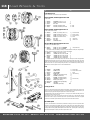
120 Brake Master Cylinder & Pedal
Type 2
Master Cylinder
Type 1
Master Cylinder
3
Type 3
Master Cylinder
ill. Part Number
No
Description
Qty.
Req.
Details
Brakes - An Introduction
Note: The changes wrought on the pedal box and brake master cylinder look complicated, but can reasonably
be defined as follows.
On the previous 948 & 1098cc Sprites and Midgets, a 'dual' cylinder supplied both the single line brake system
and the clutch system. From the start of production of the 1275 cars in 1967, new separate brake and clutch
master cylinders were introduced (the brake master cylinder becomes 'Type 1' here), necessitating a new pedal
box design. A short time later, the North American spec. cars were equipped with dual line brakes (a feature not
to be found on UK and European cars until 1978); at this time they also acquired a mechanical brake light switch
fitted in a hole in the pedal box (UK and European cars used a hydraulic switch in the circuit).
Gradually the factory rationalised the pedal boxes, phasing out the non-pierced item and instead giving the UK
& European cars the American pedal box with the hole blanked off with a plug.
(Continued)
BRADFORD 01274 735 537 . BRISTOL 0117 923 2523 . DARLINGTON 01325 281 343
Brake Master Cylinder & Pedal 121
ill. Part Number
No
Description
Qty.
Req.
Details
(Continued from previous page)
Upon introduction of the Midget 1500 in 1975, the brake system was changed; the master cylinder remained
the same but the hydraulic brake light switch was dropped in favour of the American-type mechanical switch
(so the blanking plug was no longer required).
For a brief period in 1977-1978 a brake master cylinder with a plastic remote reservoir was used ('Type 2'),
necessitating a pedal box with a bracket to hold the reservoir. After this time dual line brakes were fitted to all
Midget 1500's, using a new (in the UK and Europe) master cylinder with integral plastic reservoir ('Type 3'.
Two other details should be mentioned here.
Safety legislations in France and the 'Benelux' countries (Belgium, Netherlands, Luxembourg) required that the
brake fluid level and condition be visible without having to remove the filler cap; for those specific markets a
translucent plastic extension was screwed on to the top of a Type 1 master cylinder throughout sales of Sprites
and Midgets to those countries.
Also take note that while the Type 1 master cylinder was ostensibly the same from 1967 though to mid-1977,
in fact the internal details were changed at G-AN6-169643 approx. in Midget 1500 production; the later type,
only identifiable by circular marks on the cylinder casting, was henceforth supplied as a service replacement for
earlier cars. The moral is that replacing the master cylinder is easy; however if you intend to rebuild your old
cylinder you must clearly establish which one you have before ordering components for it.
Brake Pedal & Pedal Box
AHA8065
PEDAL BOX
1
AHA8408
CHA756
1 {
}
1 {
|
}
1
G-AN4 and H-AN9
to mid-1969
PEDAL BOX
G-AN4 and H-AN9 from
(with brake light switch hole blanked off,
mid-1969; G-AN5; H-AN10;
rubber plug on all models except G-AN6)
A-AN10; to G-AN6-200000
PEDAL BOX
from G-AN6-200001
(with holes for mounting remote M/cyl reservoir bracket)
(no hole for brake light switch)
3
4
5
6
7
8
9
10
11
12
AHA8072
SE604051
SH604051
GHF331
RFR204
AHA8074
AHA8073
AHA8076
WL700101
ZPT1006
GASKET (pedal box to footwell)
SCREW
SCREW
WASHER, locking
PLUG, rubber (brake light switch hole)
COVER PLATE, pedal box
GASKET, pedal box cover plate
SCREW, taptite (cover to pedal box)
WASHER, locking
SCREW
1
2 { pedal box to body
6 }
8
1
not G-AN6.
1
1
3
3
1
14
15
16
17
18
20
53K3157
AHA8145
AHA8146
SH604051
GHF331
AHA9723
WASHER, plain,
BLANKING PLATE (pedal box aperture)
GASKET, blanking plate
SCREW, blanking plate to body
WASHER, locking
PEDAL, brake
1
1
1
4
4
1
21
22
23
24
25
26
27
28
29
30
CHA791
LBS810
AHA8075
GHF304
GHF333
FNZ506
AAA1628
AHA5326
CLZ513
GHF301
GHF502
PEDAL, brake
BUSH, pedal
BOLT, pivot (brake & clutch pedals)
WASHER, plain
WASHER, locking
NUT
RETURN SPRING, brake pedal
PAD, pedal rubber
CLEVIS PIN
WASHER, plain
SPLIT PIN
1
2
1
1
1
1
1
1
1
1
1
(cover & spare ignition key to pedal box)
(for spare ignition key)
{
|
|
}
{
|
}
Passenger side
G-AN4; G-AN5; to
G-AN6-212000; H-AN9;
H-AN10; A-AN10
from G-AN6-212001
ill. Part Number
No
Description
Qty.
Req.
Details
Master Cylinders
Type 1 (G-AN4; G-AN5; to G-AN6-200000; H-AN9; H-AN10; A-AN10.)
41
42
43
GMC113
GRK1026
27H8459
MASTER CYLINDER
REPAIR KIT
PUSH ROD
1 { Plain body
1 | (no circle or groove)
1 }
44
45
46
GMC151
GRK1009
AAU3469
MASTER CYLINDER
REPAIR KIT
PUSH ROD
1 { Circle or groove
1 | on body
1 }
47
48
49
50
51
52
55
56
57
58
60
61
62
17H7560
27H7751
513123A
CLZ513
GHF301
GHF502
SH605071
GHF301
GHF332
FNZ505
BHA4661
BHA4660
BCA4964
CIRCLIP
SPRING
CAP, filler
CLEVIS PIN (push rod to pedal)
WASHER, plain
SPLIT PIN
SCREW (master cylinder to pedal box)
WASHER, plain
WASHER, locking
NUT
EXTENSION (translucent plastic)
CLIP, locking
SEAL
1
1
1
1
1
1
2
2
2
2
1 {
1 | France & Benelux countries
1 }
Type 2 (G-AN6-200001 to 212000)
65
66
67
68
69
70
71
72
73
74
BHA4810
AAU3815
37H2172
CHA793
ADU1169
AAU1711
CHA753
PMZ308
WL700101
NH910010
RESERVOIR
CAP, filler
SEAL, filler cap
HOSE, reservoir to cylinder
CLIP (hose to reservoir)
CLIP (hose to cylinder)
BRACKET, reservoir to pedal box
SCREW, bracket to pedal box
WASHER, locking
NUT
75
76
77
79
80
81
82
83
84
85
86
87
88
89
90
PMZ312
WL700101
GHF306
GMC166
GRK1009
AAU3469
17H7560
AAU8105
CLZ513
GHF301
GHF502
SH605071
GHF301
GHF332
FNZ505
SCREW, clamping (reservoir)
WASHER, locking
WASHER, plain
MASTER CYLINDER
REPAIR KIT
PUSH ROD
CIRCLIP
SPRING
CLEVIS PIN
WASHER, plain
SPLIT PIN
SCREW (master cylinder to pedal box)
WASHER, plain
WASHER, locking
NUT
1
1
1
1
1 { these clips require a
1 } crimping tool to fit them
1
2
2
a/r { use if weld nuts are missing
} from the bracket
1
1
1
1
1
1
1
1
1
1
1
2
2
2
2
Type 3 (G-AN6-212001 on)
pedal to master cyl. push rod
The Incurable Rattle
Many owners of Sprites & Midgets other than post 1976 Midget 1500's will recognise the frustration of the
following;
A light, metallic rattle from somewhere inside the back of the car, every time a manhole cover or ridge in the
road is driven over. Checked the boot lid stay? Yes. Was it loose? No.
Something rolling around in the boot? No. Boot lid lock or striker not quite aligned? No.
Exhaust mounting broken? No.
Fuel or brake pipe come loose? No.
Shock absorber bolt (or any suspension bolt) loose? Definitely not.
The answer lies with the hand brake mechanism.
The cross rods running from the centre of the rear axle out to the hand brake levers on the brakes are held by
clevis pins and split pins. Excessive play is restricted by the use of two felt washers on each clevis pin.
If there's a rattle at the back of the car that's difficult to trace, the odds are on some or all of the felt washers
being missing. When lying under the car shaking the cross rods by hand, they don't make the right sound: a dull
clunk rather than a sharp metallic rattle.
The only way to be sure is to count the felt washers; any less than two per joint and you can be sure that's
where the rattle is coming from.
95
96
97
98
99
100
101
102
103
104
105
106
107
108
109
110
111
112
113
114
115
GMC170
AAU3815
GRK1020
37H2172
27H8445
37H2763
37H2764
27H8453
514151A
27H8456
11D5070
7H7520
GHF321
BHA5132
CLZ513
GHF301
GHF502
SH605071
GHF301
GHF332
FNZ505
MASTER CYLINDER
CAP, filler
REPAIR KIT
SEAL, filler cap
CIRCLIP
SPRING
SPRING, primary
BODY, trap valve
CLIP, trap valve
ADAPTOR, outlet
GASKET, adaptor
SCREW (reservoir to master cylinder)
WASHER, shakeproof
PUSH ROD
CLEVIS PIN
WASHER, plain
SPLIT PIN
SCREW (master cylinder to pedal box)
WASHER, plain
WASHER, locking
NUT
1
1
1
1
2
1
1
2
2
2
2
4
4
1
1
1
1
2
2
2
2
DERBY 01332 756 056 . LONDON 020 8867 2020 . MANCHESTER 0161 480 6402
50
122 Front/Rear Brakes & Handbrake
Front Brakes
Rear Brakes
(Left Hand shown)
(Right Hand shown)
1275 & Early 1500
Late 1500
BRADFORD 01274 735 537 . BRISTOL 0117 923 2523 . DARLINGTON 01325 281 343
Front/Rear Brakes & Handbrake 123
ill. Part Number
No
Description
Qty.
Req.
Details
Front Brakes
1
2
3
5
6
7
10
11
12
14
BTA473
BTA472
SH605031
WE600051
BTA383
BTA469
BTA370
17H9438
17H9438E
17H9439
17H9439E
GRK5008
17H7960
17H7679*
25
26
27
30
17H8250
17H7917
3H2428
234957A
BTA789
BTC114
BTA793
BTA792
C5192A
3H550
233220A
GBP281
BACK PLATE, LH
BACK PLATE, RH
SCREW, back plate securing
WASHER, shakeproof
BRAKE DISC
BRAKE DISC
BOLT, hub to disc
CALIPER, LH, new
CALIPER, LH, recon, exchange
CALIPER, RH, new
CALIPER, RH, recon, exchange
REPAIR KIT, caliper
PISTON, caliper
O' RING, fluid channel
1
1
2
2
2
2
8
1
1
1
1
2
4
2
80
use with steel wheels only
use with wire wheels only
BOLT, bridge
PLUG
BLEED SCREW
DUST COVER, bleed screw
BOLT, caliper to stub axle
LOCK TAB
LOCK PLATE, brake hose (LH)
LOCK PLATE, brake hose (RH)
BANJO BOLT, hose to caliper
WASHER, sealing, large
WASHER, sealing, small
BRAKE PAD SET (asbestos free)
4
2
2
2
4
2
1
1
2
2
2
1
17H2460
17H7963
PS610241
SHIM , anti-squeal
RETAINER, brake pads (spring steel)
SPLIT PIN, pad retaining
4
2
4
banjo to bolt head
banjo to caliper
52
53
54
BTA566
BTA567
37H8804
37H8805
SH605071
GHF222
17H7620
17H7619
17H7618
18G619A
GWC1102
GRK2014
GWC1129
GRK2004
513118A
17H7949*
37H4642
BACK PLATE, RH
BACK PLATE, LH
BACK PLATE, RH
BACK PLATE, LH
SCREW (back plate to axle tube)
NUT, nyloc
ADJUSTER REPAIR KIT
WEDGE, screw
TAPPET (shoe adjusting)
BRAKE ADJUSTING SPANNER
WHEEL CYLINDER
REPAIR KIT
WHEEL CYLINDER
REPAIR KIT
BLEED NIPPLE
CIRCLIP
GASKET
1
1
1
1
8
8
1
2
4
1
2
2
2
2
2
2
2
55
56
57
17H7949T*
17H7613*
17H7622*
CIRCLIP FITTING TOOL (2 piece)
WASHER, 'belleville'
CIRCLIP (wheel cylinder to back plate)
1
2
2
Rear Brakes
40
41
42
45
46
47
50
51
{ G-AN4; G-AN5;
} H-AN9; H-AN10; A-AN10
{ G-AN6
}
{ G-AN4; G-AN5;
} H-AN9; H-AN10; A-AN10
{ G-AN6
}
{ wheel cylinder
} to back plate
alternative to item 53
*Note: Originally a 'Belleville' washer & external circlip were used to secure the wheel cylinder. Later the
wheel cylinder manufacturer (Lockheed) superseded this method to a three toothed circlip; this is the device
supplied with the wheel cylinder today. It's a horror to fit (though, it gets easier with practice), so Lockheed made
a special tool for the job. If you invest in the tool, you'll be glad to know you can lend it out (for a favour,
naturally) to friends with Minis, MGB's, Triumph 2000's etc.- they all use the same circlip. Alternatively, you could
buy the traditional hardware (items. 55 & 56) and banish installation problems altogether.
60
61
65
66
67
70
71
72
73
74
17H2824
17H2825
17H7612
GBS834AF
17H7947
17H7948
17H7621
2A7168
2A7228
SF604051
NH606061
BTA493
LEVER, handbrake, RH
LEVER, handbrake, LH
GAITER, handbrake lever
BRAKE SHOE SET (asbestos free)
SPRING, shoe return (top) (RH)
SPRING, shoe return (top) (LH)
SPRING, shoe return (bottom)
BRAKE DRUM
PLUG, rubber
SCREW, drum securing
NUT
LOCK TAB
82
84
85
86
87
88
89
90
91
92
93
94
95
96
97
98
99
AHA6406
CHA567
AAU2492
7H5948
MPS4304
7H5950
7H5951
17H2093
7H5946
7H5947
17H786
AWZ104
GHF500
GHF323
GHF202
SF605051
2A7291
SH605051
GHF332
Hand Brake Cable
See also 'Performance & Tuning' in Accessories for Uprated Brake Pads.
31
32
33
Description
Qty.
Req.
Details
Hand Brake Lever Assembly
*Warning: You can only get to this O' ring by splitting the caliper halves; under no circumstances should
you do so unless, you are an experienced brake specialist.
15
16
17
18
20
21
22
ill. Part Number
No
1
1
2
1
1
1
2
2
2
4
8 { for wire wheels only
4 }
100
101
102
105
106
107
108
109
115
116
117
118
119
120
121
122
123
125
126
127
130
131
CLZ515
GHF301
GHF502
GVC1019
UHN305
CLZ414
GHF300
GHF501
ATA7320
SH605051
GHF301
GHF332
GHF201
2A7058
2K5820
2A7057
LN30041
CLZ314
6K690
GHF500
BTA498
BTA497
BTA494
BTA495
132 2K6930
133 2K5291
134 GHF500
HANDBRAKE LEVER, chrome
HANDBRAKE LEVER, black
SWITCH, hand brake warning light
PLUNGER, chrome
PIN, plunger
SPRING, plunger
WASHER, rubber
ROD, pawl operating
PAWL
RATCHET
LINK, main spindle
WASHER
SPLIT PIN
WASHER, shakeproof
NUT
SCREW, ratchet to bracket
BRACKET
SCREW, bracket to transmission tunnel
WASHER, locking
1
to G-AN6-166303
1 { from G-AN6-166304
1 }
1
1
1
1
1
1
1
1
1
1
1
1
2
1
2
2
(G-AN4; G-AN5; to G-AN6-182000; H-AN9; H-AN10; A-AN10)
CLEVIS PIN, cable to handbrake
WASHER, plain
SPLIT PIN
HANDBRAKE CABLE
GREASE NIPPLE
CLEVIS PIN, cable to balance lever
WASHER, plain
SPLIT PIN
SUPPORT, balance lever
SCREW, support securing
WASHER, plain
WASHER, locking
NUT
CARRIER, balance lever
WASHER, felt
BALANCE LEVER
GREASE NIPPLE
CLEVIS PIN,
WASHER, felt
SPLIT PIN
CROSS ROD (RH)
CROSS ROD (LH)
CROSS ROD (RH)
CROSS ROD (LH)
CLEVIS PIN (cross rod to brake lever)
WASHER, felt
SPLIT PIN
1
1
1
1
1
1
1
1
1
2
2
2
2
1
1
1
1
2
4
2
1
1
1
1
2
4
2
balance lever to cross rod
{ for steel wheels only
}
{ for wire wheels only
}
Hand Brake Cable (G-AN6-182001 on)
137
138
139
140
141
142
143
144
145
146
150
151
152
153
154
155
156
160
161
162
CLZ515
GHF301
GHF502
GVC1008
CHA634
AHH6752
AHC156
SH604041
GHF300
GHF331
GHF200
CHA637
CHA635
GHF117
GHF331
CHA636
SH605061
GHF332
CLZ411
GHF300
GHF501
CLEVIS PIN, cable to handbrake
WASHER, plain
SPLIT PIN
HANDBRAKE CABLE
HANDBRAKE CABLE
BRACKET (cable to differential)
CLIP, cable to bracket
SCREW
WASHER, plain
WASHER, locking
NUT
STRAP, rubber
PLATE (clamping strap to bracket on axle)
SCREW, plate and strap to bracket
WASHER, locking
PLATE (clamping strap to bracket on cable)
SCREW, plate and strap to cable
WASHER, locking
CLEVIS PIN (cable to brake lever)
WASHER, plain
SPLIT PIN
1
1
1
1
1
1
1
1
1
1
1
1
2
2
2
1
1
1
2
2
2
for steel wheels only
for wire wheels only
DERBY 01332 756 056 . LONDON 020 8867 2020 . MANCHESTER 0161 480 6402
52
124 Brake Pipes, Hoses & Fittings
SINGLE LINE SYSTEMS
1275
Single Line
Brakes
ill. Part Number
No
Description
Qty.
Req.
Details
1275 Single Line Brakes
ill. Part Number
No
Description
Qty.
Req.
Details
Unions, Brake Light Switch and Fittings
(G-AN4; G-AN5; H-AN9; H-AN10; A-AN10)
Brake Pipes
GAC5032
GAC6032
1
GPP28AA
BRAKE PIPE KIT (RHD)
BRAKE PIPE KIT (LHD)
BRAKE PIPE, RHD
master cylinder to 5 way union
2
GPP64AA
BRAKE PIPE, LHD
3
GPP14AC
BRAKE PIPE
4
GPP50AC
BRAKE PIPE
5
GPP72AC
BRAKE PIPE
master cylinder to 5 way union
5 way union to RH front brake hose
5 way union to LH front brake hose
5 way union to rear brake hose
6
GPP20AA
BRAKE PIPE
7
GPP32AA
BRAKE PIPE
3 way union to RH rear brake
3 way union to LH rear brake
1 { copper pipes
1 }
1 {
|
1 |
|
1 | steel pipes
|
1 |
|
1 |
|
1 |
|
1 |
}
Brake Hoses and Fittings
10
11
12
14
15
GBH157
C5192A
3H550
233220A
1G9198
BRAKE HOSE, front
BANJO BOLT (front hose to caliper)
WASHER, copper
WASHER, copper
LOCK PLATE
16
17
20
21
22
23
24
GHF202
GHF323
GBH158
233220A
1G9198
GHF202
GHF323
NUT
WASHER, shakeproof
BRAKE HOSE, rear
WASHER, copper
LOCK PLATE
NUT
WASHER, shakeproof
2
2
2
2
2
bolt head to banjo
banjo to caliper
(front brake hose to front hose to suspension tower)
2
2
1
2
2
2
2
30
31
32
33
34
35
36
37
17H7108
GHF101
GHF331
C16062A
3H2424
BH604101
GHF331
GHF200
UNION, 5 way
BOLT (union to RH inner wing)
WASHER, locking
SWITCH, brake light
UNION, 3 way
BOLT (3 way union to rear axle)
WASHER, locking
NUT
1
1
1
1
1
1
1
1
CLIP, metal,
2 {
}
2 {
}
2
2
2
2
1
1
1
1
1
2 {
2 |
2 |
2 |
1 |
|
1 }
2
(fits on union)
Pipe Clips
40
6K35
(brake pipe to front crossmember)
41
GHF1192
CLIP, plastic,
42
43
44
45
46
47
48
49
50
53
54
55
56
57
PCR307
PMZ308
GHF306
GHF220
PCR309
GHF200
GHF331
GHF300
PCR309
CHR307
PMZ305
WL700101
GHF206
PCR309
CLIP (brake pipe to tunnel & footwell)
SCREW, clip to tunnel & footwell
WASHER, plain
NUT, nyloc
CLIP (brake pipe to footwell side)
NUT, clip to footwell side
WASHER, locking
WASHER, plain
CLIP (brake pipe to pedal box)
CLAMP (brake/clutch pipes to bulkhead)
SCREW, clamp to bulkhead
WASHER, locking
NUT, LH steering only
CLIP brake pipe to screw securing
58
59
AHH6247
ACA5375
SPACER (between clip & blanking plate)
STRAP (brake pipe to rear axle)
(brake pipe to front crossmember)
(pedal box aperture blanking plate)
G-AN4; to G-AN5-114642;
H-AN9; H-AN10; A-AN10
from G-AN5-114643
RHD
LHD
rear hose to 3 way union
BRADFORD 01274 735 537 . BRISTOL 0117 923 2523 . DARLINGTON 01325 281 343
Brake Pipes, Hoses & Fittings 125
SINGLE LINE SYSTEMS
1500
Single Line
Brakes
ill. Part Number
No
Description
Qty.
Req.
Details
1500 Single Circuit Brakes
Brake Pipes
Note: This catalogue does not cover LHD North American vehicles;
if you require components for a LHD Midget 1500, please telephone your local branch for details.
GAC5033
GPP34AC
66
GPP60AA
BRAKE PIPE KIT (RHD)
BRAKE PIPE
master cylinder to RH front brake hose
BRAKE PIPE
master cylinder to 3 way union
67
GPP12AC
BRAKE PIPE
3 way union to LH front brake hose
68
GPP82AC
69
GPP20AA
BRAKE PIPE
3 way union to rear brake hose
BRAKE PIPE
3 way union to RH rear brake
70
GPP32AA
BRAKE PIPE
3 way union to LH rear brake
71
72
73
74
7H7851
90577478
3H550
233220A
BANJO UNION, master cylinder outlet
BANJO BOLT, special
WASHER, copper
WASHER, copper
1
1 {
|
1 |
|
1 |
|
1 |
|
1 |
|
1 |
}
1
1
1
1
copper
GBH157
C5192A
3H550
233220A
GHF202
GHF323
GBH158
233220A
BRAKE HOSE, front
BANJO BOLT (front hose to caliper)
WASHER, copper
WASHER, copper
NUT (front hose to inner wheel arch)
WASHER, shakeproof
BRAKE HOSE, rear
WASHER, copper
88
89
90
1G9198
GHF202
GHF323
LOCK PLATE
NUT
WASHER, shakeproof
Qty.
Req.
Details
2
2
2
2
2
2
1
2 {
}
2
2
2
95
96
3H2424
GHF101
UNION, 3 way
BOLT
97
98
99
100
101
102
GHF331
BH604101
GHF331
GHF200
BHA4675
NT606041
WASHER, locking
BOLT (3 way union to rear axle)
WASHER, locking
NUT
SWITCH, brake light
NUT
2
1 { 3 way union to
} LH inner wing
1
1
1
1
1
(fits on pedal box)
1
CLIP, plastic (alternative)
CLIP, metal (alternative)
CLIP (brake pipe to heel board & footwell)
SCREW (clip to heel board & footwell)
WASHER, locking
WASHER, plain
CLIP (brake pipe to footwell top)
SCREW, clip to footwell top
CLIP (brake pipe to bulkhead)
SCREW, clip to bulkhead
WASHER, locking
WASHER, plain
NUT
CLIP (brake pipe to pedal box screw)
STRAP (original)
STRAP (replacement)
2
2
2
2
2
2
2
2
2
2
2
2
2
1
2
2
Pipe Clips
steel pipes
bolt head to banjo
banjo to master cylinder
Brake Hoses & Fittings
80
81
82
83
84
85
86
87
Description
Unions, Brake Light Switch & Fittings
(to G-AN6-212000)
65
ill. Part Number
No
104
105
106
107
108
109
110
111
112
113
114
115
116
117
118
bolt head to banjo
banjo to caliper
rear hose to
3 way union
GHF1192
6K35
PCR307
PMZ308
WL700101
GHF306
PCR307
GHF426
PCR307
PMZ308
WL700101
GHF306
GHF206
PCR309
ACA5375
ACH8650
{ pipe to floor support channel
}
{ brake pipe
} to rear axle
Brake Pipe Lengths & Fittings
NI
125
126
127
EF125
MPKF125
TM606031
TN606031
BRAKE PIPE, steel
BRAKE PIPE, cupro-nickel
TUBE NUT, male
TUBE NUT, female
a/r
a/r
a/r
a/r
{ 7 metre roll
}
{ (3/8" UNF thread)
}
DERBY 01332 756 056 . LONDON 020 8867 2020 . MANCHESTER 0161 480 6402
54
126 Brake Pipes, Hoses & Fittings
DUAL LINE SYSTEM
Iron Valve
1500
Dual Line
Brakes
Brass Valve
BRADFORD 01274 735 537 . BRISTOL 0117 923 2523 . DARLINGTON 01325 281 343
Brake Pipes, Hoses & Fittings 127
DUAL LINE SYSTEM
ill. Part Number
No
Description
Qty.
Req.
Details
1500 Dual Line Brakes
(G-AN6-212001 on
Brake Pipes
Note: While the Midget 1500 was manufactured (like its predecessors) in both RHD LHD versions, the latter were
exclusively North American specification cars. This catalogue does not cover North American vehicles; if you require
a brake pipe (or any other component) for a LHD Midget 1500, please telephone your nearest branch for details.
1
GAC5061
GPP66AT
BRAKE PIPE KIT, RHD
BRAKE PIPE
2
GPP60AA
BRAKE PIPE
3
GPP42CT
front master cylinder outlet to PDWA valve
rear master cylinder outlet to PDWA valve
BRAKE PIPE
PDWA valve to RH front brake hose
4
GPP10CT
BRAKE PIPE
PDWA valve to LH front brake hose
5
GPP82AC
BRAKE PIPE
PDWA valve to rear brake hose
6
GPP20AA
BRAKE PIPE
7
GPP32AA
BRAKE PIPE
3 way union to RH rear brake
3 way union to LH rear brake
1
copper
1 {
|
1 |
|
1 |
| steel pipes
1 |
|
1 |
|
1 |
|
1 |
}
PDWA Valve
There are two types of 'Brake Pressure Differential Warning Actuator' (PDWA) valves which may be found under
the bonnet of your dual line-braked Midget 1500. They may be easily identified by the material that the main valve
body is made from.
The one you are more likely to find is the cast iron item (AAU2583), which was the factory fitment during the
period in which your car was built. On earlier USA market cars, plus other vehicles from the British Leyland line
up, a brass PDWA valve (13H5905) was fitted; new brass valves have at times been more prevalent in the
classic car spares market, with the result that many are now fitted to late model Midget 1500's.
As assemblies, the cast iron and brass valves are interchangeable; however the actuator switches screwed
into the bodies are not.
The switch to fit the brass valve, RTC826, has a coarse pitch thread of approximately 9mm diameter, whereas the switch for the cast iron valve, AAU1700A, has a fine pitch thread of approximately 15mm diameter.
10
11
12
14
15
20
21
22
23
24
AAU2583
AAU1700A
BAU1775
BH604141
GHF331
13H5905
RTC826
BAU1704A
GHF101
GHF331
VALVE ASSEMBLY, PDWA (cast iron)
SWITCH, actuator
REPAIR KIT, valve
BOLT (valve to LH front inner wing)
WASHER, locking
VALVE ASSEMBLY, PDWA (brass)
SWITCH, actuator
REPAIR KIT, valve
SCREW (valve to LH front inner wing)
WASHER, locking
1
1
1
1
1
1
1
1
1
1
{
|
| original (cast iron)
|
}
{
|
| Replacement (brass)
|
}
Brake Hoses and Fittings
30
31
32
33
34
35
36
37
38
39
40
GBH157
C5192A
3H550
233220A
GHF202
GHF323
GBH158
233220A
1G9198
GHF202
GHF323
BRAKE HOSE, front
BANJO BOLT, front hose to caliper
WASHER, copper
WASHER, copper
NUT (front hose to inner wheel arch)
WASHER, shakeproof
BRAKE HOSE, rear
WASHER, copper
LOCK PLATE
NUT
WASHER, shakeproof
2
2
2
2
2
2
1
2
2
2
2
bolt head to banjo
banjo to caliper
3H2424
BH604101
GHF331
GHF200
BHA4675
NT606041
UNION, 3 way
BOLT, 3 way union to rear axle
WASHER, locking
NUT
SWITCH, brake light
NUT
GHF1192
6K35
PCR307
CLIP, plastic (alternative)
CLIP, metal (alternative)
CLIP (pipe to heel board & footwell)
54
55
56
57
60
PMZ308
WL700101
GHF306
PCR311
AHA8683
SCREW (clip to heel board & footwell)
WASHER, locking
WASHER, plain
CLIP, pipe to steering rack mount
CLIP
61
62
AHH6247
13H9593
SPACER, between clip & blanking plate
CLIP, bulkhead
63
ACA5375
ACH8650
(for brake pipes between master cylinder and PDWA valve)
STRAP (original)
2 { brake pipe
STRAP (alternative)
2 } to rear axle
Qty.
Req.
Details
2
2
2
2
1
(brake pipes to screw securing pedal box aperture blanking plate)
1
5
Brake Pipe Lengths & Nuts
70
71
72
73
EF125
MPKF125
TM606031
TN606031
BHA4706
BRAKE PIPE, steel
BRAKE PIPE, cupro-nickel
TUBE NUT, male
TUBE NUT, female
TUBE NUT, male
a/r
a/r
a/r
a/r
a/r
{ 7 metre roll
}
{ 3/8" UNF thread
}
7/16"
UNF thread
Brake Bleeding and Dual Circuit Brakes
The recommended replacement period for the originally specified brake fluid is 2 years.
Girling, the manufacturers of brake systems fitted on many motor cars, write;
“To enable brake fluid to work, it has to remain incompressible even at the high temperatures which can
be generated within the brake system - up to 170°C. However, brake fluid is hygroscopic, which means
that by its chemical nature it absorbs moisture (water) from the atmosphere through the reservoir
breather & the flexible hoses.
When the moisture builds up there is a major risk that, under heavy braking, the fluid will 'boil'. The
water in the system near the 'hot spots' (calipers & wheel cylinders) turns to vapour and then compresses. The technical term is vapour lock.
The reality is at best a soft, spongy pedal, at worst total brake failure.”
They recommend that the boiling point of brake fluid should be tested periodically to indicate its moisture
content. Such test equipment may not be readily available to the private owner.
Thus the 2 yearly renewal procedure should be adopted.
The brake bleeding operation is clearly detailed in all quality service manuals for all types of car. What is missing
from many publications is how to cope with dual circuit systems fitted with the pressure differential warning
actuator (PDWA) valve. The trick with dual circuit systems incorporating the PDWA valve is to take matters
slowly, bleeding one fully opened screw at a time, unless you can rely on assistants who would otherwise be
required. Do not pump up pressure, nor push the pedal through its full stroke during the bleeding operation.
After bleeding the brakes completely, the brake warning light on the fascia is often illuminated.
This will have been caused during the bleeding operation by a differential in fluid pressure in the system moving
the valve shuttle, actuating the switch and blocking off one fluid circuit (exactly what it is supposed to do in the
event of failure of one of the brake circuits). To re-centralise the shuttle the following steps should be taken.
1. Fit a rubber tube, as used in the bleeding operation, to a bleed screw at the opposite end
of the car to that which has just been bled. Submerge the other end of the tube in a container of appropriate
brake fluid.
2. Open the bleed screw.
3. Switch on the ignition but DO NOT START THE ENGINE (the brake warning light will glow).
4. Exert a steady but light pressure on the brake pedal until the brake light is extinguished.
The moment the light goes out close the bleed screw and stop pressing the pedal (a click may be felt through
the pedal as the shuttle returns to its mid-position).
5. Tighten all bleed screws.
6. When the system is sealed, depress the brake pedal and test for 'feel'. The brake failure warning light should
not glow if the brakes are correctly bled and the PDWA valve shuttle is set centrally.
Note: If the pedal is pushed too hard the shuttle will move to the other side of the valve, thus requiring the
procedure to be repeated on a brake bleed screw at the opposite end of the car.
Clutch & Brake Fluids
When did you last change your Clutch/Brake fluid?
DOT 3 fluid ought to be completely discarded, DOT 4 ('GBF4') should be installed and replaced every 2
years, as recommended by manufacturers.
1
1
1
1
1
1
(fits on pedal box)
Pipe Clips
51
52
53
Description
rear hose to 3 way union
Unions, Brake Light Switch and Fittings
45
46
47
48
49
50
ill. Part Number
No
2 { pipe to floor support channel
2 }
2
Brake/Clutch Fluid (DOT 4 Specification);
NI GBF4102
(500ml)
NI GBF4103
(1 Litre)
NI GBF4104
(5 Litre)
a/r
a/r
a/r
Silicone Brake/Clutch Fluid (DOT 5 Specification);
NI ABF3
(500ml)
NI ABF4
1 Litre)
a/r
a/r
Racing Brake/Clutch Fluid (DOT 5 Specification);
NI GBF5102
(500ml)
NI GBF5103
(1 Litre)
a/r
a/r
DERBY 01332 756 056 . LONDON 020 8867 2020 . MANCHESTER 0161 480 6402
56
128 Steering Column & Wheels
Collapsible type
Column
Non-Collapsible
type Column
BRADFORD 01274 735 537 . BRISTOL 0117 923 2523 . DARLINGTON 01325 281 343
Steering Column & Wheels 129
ill. Part Number
No
Description
Qty.
Req.
Details
Steering Columns, Non-Collapsible
1
2
3
4
5
6
17H9185
17H9184
27H2359
27H2361
27H2358
27H2360
37H4769
37H4766
37H4770
37H4771
37H4772
AHA5893
13H569
13H568
AHA5435
COLUMN, inner RHD/LHD (no lock)
COLUMN, outer RHD/LHD (no lock)
COLUMN, inner RHD (accepts lock)
COLUMN, inner LHD (accepts lock)
COLUMN, outer RHD (accepts lock)
COLUMN, outer LHD (accepts lock)
COLUMN, inner RHD/LHD (no lock)
COLUMN, outer RHD/LHD (no lock)
COLUMN, inner RHD/LHD (accepts lock)
COLUMN, outer RHD (accepts lock)
COLUMN, outer LHD (accepts lock)
BUSH, upper
BUSH, lower
CLIP, lower bush securing
SEAL, draught excluding
1
1
1
1
1
1
1
1
1
1
1
1
1
1
1
{
|
|
| G-AN4; H-AN9
|
}
{
|
| to G-AN5-105500
| H-AN10; A-AN10
|
|
|
|
}
Steering Columns, Collapsible
Note: 1275 Sprites & Midgets were freely available with RHD or LHD specification.
While the Midget 1500 (G-AN6) was manufactured in both RHD and LHD versions, the latter were exclusively
North American market cars. This catalogue does not cover North American vehicles; if you require a steering
column part (or any other component) for a LHD Midget 1500, please contact your local branch for details.
10
AHA9792
AHA9792E
COLUMN ASSEMBLY, RHD, new
COLUMN ASSEMBLY, RHD, *recon'
*(exchange)
CHA558
CHA558E
COLUMN ASSEMBLY, RHD, new
COLUMN ASSEMBLY, RHD, *recon'
*(exchange)
AHA9882
AHA9882E
COLUMN ASSEMBLY, LHD, new
COLUMN ASSEMBLY, LHD, *recon'
*(exchange)
11
12
14
MGP1050B
MPB1002
AHA9801
CHA457
CHA559
BUSH, upper
BUSH, lower
SEAL, draught excluding
SEAL, draught excluding
SEAL, draught excluding
1 {
1 | G-AN5-105501 on;
} to G-AN6-170989
1 {
1 | G-AN6-170990 on.
}
1 {
1 | G-AN5-105501 on.
}
1
1
1
from G-AN5-105501
1
to G-AN6-170989
1
from G-AN6-170990
Steering Column Mountings
20
21
22
23
24
25
26
27
28
29
30
31
32
53K1013
LNZ104
2A6144
2A6132
GHF101
GHF331
GHF300
4B2502
2A6133
SE504091
GHF331
GHF300
BOLT, clamping
NUT, locking
SHIM
BRACKET, column mounting
SCREW, bracket to body
WASHER, locking
WASHER, plain
SEATING, column bracket
CAP, bracket
SCREW, cap to bracket
WASHER, locking
WASHER, plain
STEERING LOCK
1
1
a/r
1
2
2
2
1
1
2
2
2
1
36
37
18G8387
18G8388
18G8713
18G8714
COWLING, top & bottom halves (RHD)
COWLING, top & bottom halves (LHD)
COWLING, top & bottom halves (RHD)
COWLING, top & bottom halves (LHD)
1
1
1
1
RMP214
SCREW, cowling (top to bottom half)
4
see page 157
{
}
{
|
}
G-AN4, H-AN9 (without
(headlamp flash on stalk)
G-AN4, H-AN9 (with headlamp flash on stalk) all G-AN5,
G-AN6, H-AN10, A-AN10
Note: Horn push pads are included here as they are seen to be part of the steering wheel. However, the full range of
horn pushes and their associated components may be found in 'Switches & Controls (Fascia & Column)' on page 157.
AHA9193
BHA4442
BHA4441
BHH111*
31G1039*
BHA4979*
BHA5010*
STEERING WHEEL (wire spokes)
HORN PUSH, 'MG' logo
HORN PUSH, 'Austin' logo
STEERING WHEEL (five hole spokes)
CENTRE PAD
BADGE, centre pad, 'MG' logo
BADGE, centre pad, 'Austin' logo
1
1
1
1
1
1
1
50
BHH291
STEERING WHEEL (five hole spokes)
51
BHH786
STEERING WHEEL (slotted spokes)
52
53
54
BHH1307
BHA5053
BHA5043
STEERING WHEEL (embossed spokes)
HORN PUSH, no logo (for Sprite)
HORN PUSH, black 'MG' logo
BHA5135
HORN PUSH, red 'MG' logo
AAU1161
HORN PUSH, gold 'MG' logo
CHA748
CHA747
BHH1994
BHH2687
ACH6001
6K900
CENTRE PAD, hollow centre
BADGE, black/silver 'MG' logo (original)
BADGE, black 'MG' logo (alternative)
BADGE, red/silver 'MG' logo (alternative)
NUT (steering wheel to column)
WASHER, shakeproof
55
56
57
58
Qty.
Req.
1 {
|
}
1 {
}
1 {
1 }
1 {
}
1 {
}
1 {
}
1 {
1 |
1 |
1 }
1
1
Details
G-AN5-89515 to
G-AN5-123730;
H-AN10-86303 on; A-AN10
G-AN5-123731 to
G-AN5-135881
G-AN5-135882 on; G-AN6
H-AN10-86303 on; A-AN10
G-AN5-89515 to
G-AN5-105500
G-AN5-105501 on;
to G-AN6-200000
used on selected
1975 G-AN6 cars
G-AN6-200001 on.
Removing and Refitting Components
1. The steering lock.
There are several ways of removing steering lock shear bolts, which by security conscious design will have
sheared their heads off during fitting. The methods range from the ham-fisted (ignoring the bolts and simply
hack-sawing the lock off, thereby destroying it ) to a couple of more rational ideas described below.
If there is any of the shear bolt material proud of the steering lock casting, it may be possible to create a slot
across it with careful use of a hacksaw and then undo the bolt with a screwdriver. If this is not possible, the bolt
can be undone by putting the point of a centre punch near the outer edge of the sheared surface of the bolt,
then angling the punch so that when struck by a hammer it knocks the bolt round in an anti-clockwise
direction. Repeating this action will, of course, eventually undo the bolt.
Granted, it's a slow procedure, but it works every time.
Drilling the bolts out is not really recommended if the lock is to be saved; unless you are remarkably skilful (or
lucky) in your aim, the drill will probably drift into the soft metal of the lock casting, leaving rather too much of
the relatively harder bolt complete. In the same vein, using an 'Easyout' (a device for removing broken studs) is
a bit of a gamble; if the Easyout breaks, as it will if you get a little too enthusiastic with it, you will be left
staring at something that's definitely too hard to drill out.
2. The steering wheel.
When trying to ease the steering wheel off the tapered splines on the top of the column without the aid of the
correct wheel pulling tool (i.e. jiggling it from side to side and tugging at the same time, or tapping the back of
the wheel with a soft faced hammer), make sure that the wheel retaining nut is still held on the end of the
column by a thread or two.
You'll have saved face - literally - when the wheel eventually breaks free in a hurry from its splines.
Going back to the start of the task, scratch a mark on the top of the inner column to match another on the wheel
centre, so that later during re-assembly you don't have to go through the hit and miss process of trying to get
the wheel on straight again.
Steering Wheels
40
41
42
43
44
45
46
Description
column to steering rack
Steering Column Cowls
35
ill. Part Number
No
{
| G-AN4; H-AN9
}
{
| to G-AN5-89514;
| to H-AN10-86302
}
*The steering wheel BHH111 introduced for the 1970 model year was the first on non-American Sprites
& Midgets to be devoid of a horn push (the horn was operated from the indicator stalk). This state was not to
last for long, however, because in July 1970 a new (but similar) steering wheel was introduced with a horn push
pad in the centre. If you have an early 1970 car and you're stuck for a BHH111 steering wheel, any of the later
three wheels will do the job (BHH291 is closest to original in style - it has five hole spokes), together with an
appropriate horn push to act as a centre pad.
3. Joining the steering column to the steering rack.
Never attempt to join the column and steering rack together without the rack clamps being loose enough to
allow a little rotation of the rack in its mountings. The movement will allow the splines of the column and rack
to settle properly in line with each other; only then should all the bolts be nipped up tight: the column pinch bolt
first, followed by the rack mountings.
If the rack pinion was not quite in line, so that the column exerted a lateral pressure on it, abnormal wear on
bushes and bearings would result.
The Embarrassing Horn Fault
One sunny afternoon, you find yourself driving along in town with the hood down, generally enjoying life. You
turn a corner slowly into a crowded street in your gleaming pride and joy and....the horn blares out, whereupon
everyone stops and stares/glares at you. But you're sure you didn't touch the horn. Later, you drive over a bump
while following a taxi and the horn goes off again. You hide miserably behind the steering wheel, as much out
of sight of the taxi driver as possible. Once back at the sanctuary of your house, you wreak revenge on the horn
controls, carrying out a thorough inspection and overhaul. A couple of days later, the same embarrassing events
repeat themselves. You can't believe it.
Try this test: hold the steering wheel and try to pull it back towards yourself; then push it forwards, away from
yourself, as far as you can. You will probably be shocked at the amount of longitudinal play (though not as
shocked as when the horn goes off again).
The excessive play - which at its worst point enables the horn circuit to be unintentionally completed - is due
to worn thrust washers on the steering rack pinion.
If you fancy your chances dealing with fine tolerance shims & things, have a go at repairing it.
If you're sensible, exchange your steering rack for a new or reconditioned item.
DERBY 01332 756 056 . LONDON 020 8867 2020 . MANCHESTER 0161 480 6402
58
130 Steering Rack
'Early' Rack 1967-1971
(G-AN4; to G-AN5-114642; H-AN9; H-AN10; A-AN10)
'Late' Rack 1972-1979
(G-AN5-114643 on; G-AN6)
ill. Part Number
No
Description
Qty.
Req.
Details
Steering Racks
Two types of rack were fitted, the Morris Minor sourced item giving way to the later Triumph design
(intermittently) from GAN5-114643. The racks are not interchangeable unless the mounting brackets, track rod
ends and steering arms (on the stub axles) are also changed.
'Early' Rack 1967-71
(G-AN4; to G-AN5-114642; H-AN9; H-AN10; A-AN10)
ACG6010
ACG6010E
ACG6009
ACG6009E
BTA1096
BTA1096E
BTA1097
BTA1097E
RACK, RHD, new
RACK, RHD, exch. recon
RACK, LHD, new
RACK, LHD, exch. recon
RACK, RHD, new
RACK, RHD, exch. recon
RACK, LHD, new
RACK, LHD, exch. recon
1
1
1
1
1
1
1
1
{
|
|
}
{
|
|
}
to G-AN4-61165
to H-AN9-72528
from G-AN4-61166
to G-AN5-114642
from H-AN9-72529
H-AN10; A-AN10
ill. Part Number
No
Description
1
ACA6020
ACA6019
ACA6029K
ACA6029
BMK924A
3H2963
HOUSING, rack, RHD
HOUSING, rack, LHD
GAITER KIT (2 required)
GAITER, rack
STEEL CLIP, large
STEEL CLIP, small
1
1
2
2
2
2
GSJ169
7H3762
7H3565
NL607041
GHF504
GHF224
GHF303
UHN305
ACH6173
TRACK ROD END
GAITER, track rod end
CLIP, gaiter
NUT, slotted
SPLIT PIN
NUT, nyloc
WASHER, plain
GREASE NIPPLE
WASHER, fibre
2
2
2
2
2
2
2
2
2
2
3
4
5
6
7
8
9
10
15
16
Qty.
Req.
Details
(one per end)
(alternative to items 8 & 9)
BRADFORD 01274 735 537 . BRISTOL 0117 923 2523 . DARLINGTON 01325 281 343
Steering Rack 131
ill. Part Number
No
20
21
22
23
24
25
26
30
31
32
33
34
35
36
37
40
41
42
43
44
45
46
47
48
50
55
57
58
59
60
61
62
63
64
Description
Qty.
Req.
ACA6018
ACA6015
ACA5304
ACA5246
ACA6031
ACA6017
ACA5301
ACA5302
ACA5303
ACA5247
TRACK ROD ASSEMBLY
TRACK ROD
BALL HOUSING, outer
SEAT, ball
BALL HOUSING, inner
SHIM, 0.002"
SHIM, 0.003"
SHIM, 0.005"
SHIM, 0.010"
LOCK TAB
2
2
2
2
2
a/r
a/r
a/r
a/r
2
ACA6026
ACA5244
ACA5248
ACA5249
ACA5275
ACA5245
ACA5284
ACA5286
ACA5285
ACA6028
ACA6027
ACA5261
BTA942
BTA941
BTA9008
RACK
PAD, damper
SPRING, pad
SHIM (0.003")
SHIM (0.010")
HOUSING, damper
PAD, secondary damper
SPRING, pad
HOUSING, secondary damper
PINION, RHD
PINION, LHD
SEAL, pinion
PINION, RHD
PINION, LHD
SEAL, pinion
1
1
1
a/r
a/r
1
1
1
1
1
1
1
1
1
1
AHA5496
ACA5307
ACA5259
ACA5260
ACA5320
AJD6155Z
GHF331
ACA5257
ACA5258
UHN305
RETAINER, pinion seal
BEARING, pinion tail
SHIM (0.003")
SHIM (0.005")
SHIM (0.010")
SCREW, bearing to rack housing
WASHER, locking
THRUST WASHER, pinion, upper
THRUST WASHER, pinion, lower
NIPPLE, rack lubrication
1
1
a/r
a/r
a/r
2
2
1
1
1
AHA5391
AHA5392
BH505121
GHF332
2A6128
BRACKET, rack mounting, RH
BRACKET, rack mounting, LH
BOLT, clamping
WASHER, locking
SEATING, rack
AHA8718
2A6129
2A6130
2A6131
SH605061
GHF103
GHF332
GHF301
SHIM, mounting bracket (1/32")
SHIM, mounting bracket (3/32")
SHIM, mounting bracket (5/32")
SHIM, mounting bracket (7/32")
SCREW (bracket to front of crossmember)
SCREW (bracket to top of crossmember)
WASHER, locking
WASHER, plain
Details
Description
Qty.
Req.
85
86
87
88
89
90
91
128024
158732
129963
120953
130031
130032
120957
TRACK ROD ASSEMBLY
TRACK ROD
BALL HOUSING, outer
SEAT, ball
BALL HOUSING, inner
SPRING, seat
SHIM (0.002")
SHIM ( 0.010")
LOCK TAB
2
2
2
2
2
2
a/r
a/r
2
146364
208375
120946
126765
120959
120949
132055
132053
133103
056935
LOCK NUT
RACK
PAD, damper
SPRING, pad
SHIM (0.002")
SHIM (0.004")
SHIM (0.010")
HOUSING, damper
PLUG, grease point
GREASE NIPPLE
2
1
1
1
a/r
a/r
a/r
1
1 { alternatives
1 }
104 37H7339
37H7340
105 128021
106 509537
107 128001
108 128008
109 120941
37H7341
110 127998
PINION, RHD
PINION, LHD
SEAL, pinion
CIRCLIP, retaining pinion
COLLAR
PIN, securing collar
SHIM (0.005")
SHIM (0.010")
BUSH, pinion, upper
1
1
1
1
1
1
a/r
a/r
1
111 127999
112 128000
114 127997
THRUST WASHER, pinion (upper)
THRUST WASHER, pinion (lower)
BUSH, pinion (lower)
1
1
1
120 AHA9959
AHA9960
121 AHA9961
122 SH605061
123 GHF332
124 SH605061
125 GHF103
126 GHF332
127 GHF301
BRACKET, rack mounting, RH
BRACKET, rack mounting, LH
CLAMP, bracket
SCREW, clamp to bracket
WASHER, locking
SCREW (bracket to front of crossmember)
SCREW (bracket to top of crossmember)
WASHER, locking
WASHER, plain
1
1
2
4
4
4
2
6
6
128 AHA8718
2A6129
2A6130
2A6131
129 145108
SHIM, mounting bracket (1/32")
SHIM, mounting bracket (3/32")
SHIM, mounting bracket (5/32")
SHIM, mounting bracket (7/32")
DAMPER PLUG, nylon
92
93
94
95
96
97
98
99
{
|
}
{
|
|
|
}
to G-AN4-61165,
to H-AN9-72528 (groove
around pinion spline)
G-AN4-61166 on,
to G-AN5-114642,
H-AN9-72529 on,
H-AN10, A-AN10 (machined
flat across pinion spline)
1
1
4
4
2
a/r
a/r
a/r
a/r
4
2
6
6
ill. Part Number
No
{
| Passenger side
| mounting only
}
37H7346
a/r
a/r
a/r
a/r
1
Details
{
| passenger side
| mounting only
}
(this plug is in the rack tube, under the passenger's side rack mounting bracket)
Oil or Grease?
Factory manuals proffer the following information on which lubricant to use in each rack:
'Late' Rack 1972-79
(G-AN5-114643 on; G-AN6)
AHA9956
AHA9956E
AHA9955
AHA9955E
RACK, RHD, new
RACK, RHD, exch. recon
RACK, LHD, new
RACK, LHD, exch., recon
1
1
1
1
70
71
72
73
74
GSV1104/5
GSV1105
GSV1104
GHC507
GHC811
EAW4321
GAITER KIT, services both ends
GAITER, driver's side
GAITER, passenger side
CLIP, small
CLIP, large (passenger side)
WIRE TIE, driver's side
1
1
1
2
1
1
75
76
77
78
79
GSJ158
EAW2270
138869
WB110061
GHF223
TRACK ROD END
GAITER, track rod end
CLIP, gaiter
WASHER, plain
NUT, nyloc
2
2
2
2
2
Early Rack (1967-71);
At regular intervals, apply a gun filled with SAE 90 Hypoid oil to the lubrication nipple on the rack housing and
give ten strokes.
Late Rack (1972-79);
Remove the grease point plug and screw in place a grease nipple (part number 056935). Turn the steering wheel
to full right hand lock; then apply a grease gun (filled with multi-purpose grease), to the nipple and give five
strokes only (over greasing may damage the gaiters). Replace the nipple with the plug.
Finally, NEVER assume that a new or reconditioned rack has been pre-filled with lubricant.
DERBY 01332 756 056 . LONDON 020 8867 2020 . MANCHESTER 0161 480 6402
60
132 Front Suspension
BRADFORD 01274 735 537 . BRISTOL 0117 923 2523 . DARLINGTON 01325 281 343
Front Suspension 133
ill. Part Number
No
Description
Qty.
Req.
Details
Shock Absorbers & Springs
1
2
3
4
5
6
7
10
11
12
14
15
16
20
GSA103
GSA103E
GSA102
GSA102E
53K1364
GHF333
GHF302
53K1389
GHF322
2A4082
CHA129
CHA570
AHA6378
21A137
53K1368
GHF301
GHF222
AHA7029*
AHA7029E*
SHOCK ABSORBER, LH, new
SHOCK ABSORBER, LH reconditioned
SHOCK ABSORBER, RH, new
SHOCK ABSORBER, RH, reconditioned
BOLT, shock absorber to frame
WASHER, locking
WASHER, plain
BOLT, fulcrum pin clamping
WASHER, shakeproof
BUFFER, shock absorber arm
ROAD SPRING, front
ROAD SPRING, front
BUMP STOP
SPRING SEAT, lower
BOLT, spring seat to lower wishbone
WASHER, plain
NUT, nyloc
LOWER WISHBONE ASSEMBLY
LOWER WISHBONE ASSEMBLY
1
1
1
1
6
6
6
2
2
2
2 {
|
}
2
2
2
8
8
8
2
2
exchange
exchange
G-AN4; G-AN5;
to G-AN6-171477;
H-AN9; H-AN10; A-AN10
from G-AN6-171478
new
reconditioned, exchange
*Note: Don't be perturbed if you own a pre-1974 car with 'handed' wishbones - i.e.
the piercings & reinforcements for mounting the anti roll bar are only in one side of each wishbone.
Only in 1974 was the anti roll bar made a standard feature (although there can't have been more than a handful of pre-1974 cars, 'Frogeye' Sprites and their ilk excepted, which didn't have one); up to this point the wishbones were indeed handed. Subsequently, wishbones became ambidextrous and that is the way they are still
supplied today.
If you still have a pair of handed wishbones in good condition, they're quite a curio & a desirable commodity to
the Concours d'Elegance aficionados. With the front suspensions propensity to fail the MOT and require complete
overhaul (the wishbones being one of the favourite sacrificial items) there can't be many left around now.
21
22
23
24
25
26
27
28
51K3424
2A4020
8G589
UHN400
2A4272
2A4024
8G621
GHF223
WELCH PLUG
FULCRUM PIN, king pin to wishbone
PLUG, screwed
GREASE NIPPLE
PIN & WASHER, inner wishbone pivot
WASHER, special, bush retaining
BUSH, rubber
NUT, nyloc
2
2
2
2
4
4
8
4
Stub Axle Assembly & King Pin
29
HMP215012*
HMP215011*
STUB AXLE & WISHBONE, LH
STUB AXLE & WISHBONE, RH
1
1
exchange
exchange
*A stub axle & wishbone assembly consists of a new king pin kit fitted to a reconditioned stub axle (with bushes reamed accordingly), attached by a new fulcrum pin to a new wishbone. No tricky assembling to be done all you have to do is attach it to the car!
30
31
BTA745
BTA745E*
BTA744
BTA744E*
STUB AXLE, LH
STUB AXLE, LH
STUB AXLE, RH
STUB AXLE, RH
32
33
35
LN30041
UHN445
GSJ230
QHQP624TCF
2A4206
2A4205
51K1769
WL700101
GHF206
BTA613
BTA607
2A4006
2A4008*
2A4007*
2A4168*
ND607041
GHF503
GHF224
GREASE NIPPLE, stub axle, lower
GREASE NIPPLE, stub axle, upper
KING PIN KIT, for one side
KING PIN KIT, car set
CORK SEAL, large
CORK SEAL, small
COTTER PIN
WASHER, locking
NUT
SEALING RING, lower
SEALING RING, upper
THRUST WASHER
SHIM, 0.012"
SHIM, 0.008"
SHIM, 0.003"
NUT, slotted
SPLIT PIN
NUT, nyloc
1
1
1
1
new
reconditioned, exchange
new
reconditioned, exchange
*A reconditioned stub axle is supplied as a sub-assembly, complete with king pin kit (the king pin bushes are
fitted and reamed to suit)
36
37
38
39
40
41
42
43
44
45
46
2
2
2
1
2
2
2
2
2
2
2
2
a/r
a/r
a/r
2
2
2
alternative to items 45 & 46
*Contrary to the usual outcome of adding shims to an assembly, these shims should be added to loosen the king
pin and taken away to tighten it (a sufficient quantity of shims are supplied in king pin kits and reconditioned
stub axles). The procedure is to fit an 0.008" and a 0.012" shim over the thrust washer, fit the top trunnion and
tighten down the top nut (if you intend to fit a nyloc nut upon assembly on the car, use your old nut now for this
test fitting). Resistance should just be felt when the stub axle is turned on the king pin and there should be no
obvious vertical play. If this isn't the case, add or subtract shims until you are satisfied.
(Continued)
ill. Part Number
No
Description
Qty.
Req.
Details
(Continued from previous column)
Too much play, on the one hand, and you'll fail the MOT. On the other hand, too much resistance and the self
centring effect of the steering will be lost - at the least disconcerting, if not dangerous.
47
50
51
52
53
54
55
56
57
60
61
63
18G1006A
2A4005
2A4028
88G274
ND606041
GHF502
BTA606
6K653
2A4010
BTA649
BTA648
AHA9958
AHA9957
53K1370
ATA4132
2K5377
REAMING TOOL, king pin bushes
TOP TRUNNION
PIN, trunnion link to shock absorber
BUSH, rubber
NUT, slotted
SPLIT PIN
DUST EXCLUDER, lower
SPRING
DUST EXCLUDER, upper
STEERING ARM, LH
STEERING ARM, RH
STEERING ARM, LH
STEERING ARM, RH
BOLT, arm securing, short
BOLT, arm securing, long
LOCK TAB
1
2
2
4
2
2
2
2
2
1
1
1
1
2
2
2
{ G-AN4; to G-AN5-114642;
} H-AN9; H-AN10; A-AN10
{ G-AN5-114643 on; G-AN6
}
Wheel Hubs
65
66
67
68
69
BTA1254
BTA339
88G322
AHA8785
2A4067
HUB ASSEMBLY
STUD
NUT, plain (steel wheels) (not Rostyle)
NUT, chrome plated (Rostyle wheels)
GREASE CAP
2
8
8
8
2
{
|
| for steel wheels only
|
}
75
76
BTA687
BTA686
BTC392
HUB, LH
HUB, RH
GREASE CAP
1 {
1 | for wire wheels only
2 }
81
82
83
84
85
86
87
GHK1142
GHS142
GHB129
GHB128
88G321
2A4003
51K328
GHF504
WHEEL BEARING KIT, front
OIL SEAL
BEARING, inner
BEARING, outer
SPACER
WASHER, special
NUT, hub
SPLIT PIN
2
2
2
2
2
2
2
2
Anti Roll Bar
See also 'Performance & Tuning' in Accessories for Uprated Suspension Kits & Conversions.
90
91
92
93
94
95
96
97
99
100
101
102
103
105
106
107
108
AHA7013
AHA7012A
AHA7011A
GHF334
GHF203
AHA7028
SH605061
GHF332
GHF201
AHH6546K
AHH6546
PMZ307
WL700101
GHF206
AHH6541
BHH2000
SH605051
GHF332
ANTI ROLL BAR, standard size
LINK ASSEMBLY, LH
LINK ASSEMBLY, RH
WASHER, locking
NUT
BRACKET, link to wishbone
SCREW, bracket securing
WASHER, locking
NUT
END STOP KIT
END STOP (limits lateral play of bar)
SCREW
WASHER, locking
NUT
BUSH, rubber
STRAP, bush mounting
SCREW
WASHER, locking
1
1
1
4
4
2
6
6
6
2
4
4
4
4
2
2
4
4
{ bar to wishbone
}
{
|
| use with standard bar
|
}
Removing The Front Suspension
It is considerably easier to dismantle the old suspension unit (consisting of the wishbone, king pin and shock
absorber) and assemble the new one on a workshop bench, rather than working within the confines of a cramped
front wheel arch. Sprites & Midgets are among many car designs where this act of comparative working luxury
may be carried out.
Removal of the suspension unit may be carried out thus:
Undo the brake caliper from the swivel axle, then tie it up under the wheel arch so that it doesn't hang from its
hose. Supporting the wishbone securely with a trolley jack, undo the bolts holding the shock absorber to the car
body. Pull the shock absorber out from under the wheel arch and let the jack down slowly, so that the wishbone
pivots down to a near vertical position. Remove the road spring (no need for spring compressors here) and then
undo the wishbone inner pivot bolts. Remove the suspension unit from the car. It's really that simple.
Refitting is the exact reverse of the above procedure.
DERBY 01332 756 056 . LONDON 020 8867 2020 . MANCHESTER 0161 480 6402
62
134 Rear Suspension
RH Rear Suspension
Assembly/Components Illustrated
ill. Part Number
No
Description
Qty.
Req.
Details
Rear Suspension
See also 'Performance & Tuning' in Accessories for Uprated Suspension & Conversion Kits.
SFK103
FITTING KIT, rear springs
1 { Includes items 21, 24, 30,
} 33, 36 for two springs
1
AHA8093
ROAD SPRING, rear
2 { G-AN4; G-AN5; H-AN9;
} H-AN10; A-AN10
CHA493
AAA629
ROAD SPRING, rear
EYE BUSH
2
2
G-AN6
2
3
4
5
6
7
8
9
10
11
15
16
17
18
19
AHA7174
SH606101
SH606071
GHF333
GHF302
AHA7180
GHF334
AHA7178
AHA7179
AHA7201
SH605071
GHF301
GHF332
GHF201
FRONT BRACKET
SCREW, bracket to floor (rear)
SCREW, bracket to floor (front)
WASHER, locking
WASHER, plain
BOLT (spring to front bracket)
WASHER, locking
WASHER, spacing (metal)
WASHER, nylon
REAR BRACKET
SCREW (bracket to boot floor)
WASHER, plain
WASHER, locking
NUT
2
4
4
8
4
2
2
4
4
2
6
6
6
6
rear spring mounting
ill. Part Number
No
Description
20
21
22
23
24
30
31
32
33
AHA7686
AHA7182
AHA7687
GHF333
GHF202
AHA8097
21G5165
ACA5139
ACA5138
PLATE & PINS, shackle
BUSH
PLATE, shackle
WASHER, locking
NUT
U BOLT, spring to axle
SADDLE, U bolt
PLATE, locating
PAD, seating
2
8
2
4
4
4
2
4
4
34
35
36
AHA7172
AHA7173
GHF302
GHF223
BRACKET, RH
BRACKET, LH
WASHER, plain
NUT, nyloc
1 { shock absorber link
1 }
8
8
40
AHH5081
STRAP, rebound
2 { G-AN4; G-AN5; H-AN9;
} H-AN10; A-AN10
41
42
BHH989
HMP215014
BH606301
STRAP, rebound
PIN (mounting strap to axle)
BOLT (strap to shock absorber bracket)
2
2
2
43
44
45
46
50
2A7306
GHF202
GHF333
PWZ206
AHH9158
TUBE, spacer
NUT
WASHER, locking
WASHER, plain
BUMP STOP, rubber
2
4
4
4
2
Qty.
Req.
Details
G-AN6
weld to axle case (replacement)
rear spring mounting
BRADFORD 01274 735 537 . BRISTOL 0117 923 2523 . DARLINGTON 01325 281 343
Rear Suspension 135
ill. Part Number
No
Description
55
GSA149
GSA149E
GSA150
GSA150E
SHOCK ABSORBER, RH
SHOCK ABSORBER, RH
SHOCK ABSORBER, LH
SHOCK ABSORBER, LH
1
1
1
1
56
57
58
59
SH606121
GHF302
PWZ206
GHF223
BOLT, shock absorber to bracket
WASHER, plain (small diameter)
WASHER, plain (large diameter)
NUT, nyloc
4
4
4
4
60
61
62
63
64
65
AAU1949A
97H222
FNZ507
GHF334
FNZ508
GHF335
LINK ASSEMBLY
BUSH, upper, link
NUT (link to shock absorber arm)
WASHER, locking
NUT, link to bracket
WASHER, locking
2
2
2
2
2
2
Qty.
Req.
Details
Hints for Suspension Assembly
new
recon, exchange
new
recon, exchange
It is suggested that you should always have a tin of copper grease or anti-seize compound around when
carrying out the re-assembly of suspension components. A dab of grease on all threads (and inside any rubber
bushes with steel inserts) will ensure ease of removal in the future.
Whilst on the subject of hardware, new nuts, bolts & washers should be used for re-assembly if possible;
emphasis should be applied to renewing locking or shakeproof washers (spring or star washers). Nyloc nuts
should never, ever be reused, especially in safety related areas like suspension.
shock absorber to spring
Don't over tighten nuts or bolts holding rubber pivot bushes in place; correct torque settings are published in
factory & aftermarket workshop manuals and should be adhered to.
If a bush is clamped down too tightly, it will not be able to insulate against shocks or provide the correct degree
of pliability. Worse than this, it will effectively be half seized, and it won't take long to seize up completely.
The result will be a broken pivot or undue wear on the components the bush is in contact with, possibly weeks
or even only days later.
New lever arm shock absorbers (the type fitted as standard to all Sprites & Midgets) require priming before
offering up to the car. This means holding the shock absorber at the angle it would normally be when on the car,
working the arm from one extreme of its travel to the other until all of the 'dead spots' you feel in the arm's
movement have disappeared.
You may appreciate that working several times from end stop to end stop is not normally encountered by the
shock absorber when fitted to the car; as a consequence, it may take some time to fully prime itself if the task
has not been carried out beforehand.
DERBY 01332 756 056 . LONDON 020 8867 2020 . MANCHESTER 0161 480 6402
64
136 Rear Axle & Propshaft
'Steel' wheels Axle Shaft
'Wire' wheels Axle Shaft
ill. Part Number
No
Description
Qty.
Req.
Details
ill. Part Number
No
BTA551
BTA551E
Rear Axle & Axle Case
1
2
3
4
5
6
7
8
BTA694
BTA695
DAM2483
DAM2484
21H6060
6K499
2A7027
2A7226
GHF201
GHF332
AHH6752
AXLE CASE, for steel wheels
AXLE CASE, for wire wheels
AXLE CASE, for steel wheels
AXLE CASE, for wire wheels
BREATHER
PLUG (filler & drain)
GASKET
STUD
NUT
WASHER, locking
BRACKET (hand brake cable support)
1 { G-AN4; G-AN5; to
1 | G-AN6-182000;
} H-AN9; H-AN10; A-AN10
1 { from G-AN6-182001
1 }
1
2
1 { differential to
8 } axle case
8
8
1
from G-AN6-182001
15
16
17
18
19
20
21
22
23
24
25
Differential
STR520EX
DIFFERENTIAL, 3.55:1
(exchange, reconditioned)
STR520
BTA550
BTA550E
CROWN WHEEL & PINION, 3.55:1
DIFFERENTIAL, 4.22:1 ratio, new
DIFFERENTIAL, 4.22:1 ratio
(exchange, reconditioned)
10
BTA539
BTA1222
BTA1222E
CROWN WHEEL & PINION, 4.22:1
DIFFERENTIAL, 3.9:1 ratio, new
DIFFERENTIAL, 3.9:1 ratio
(exchange, reconditioned)
BTA1223
CROWN WHEEL & PINION, 3.9:1
1 {
|
1 }
1 {
1 |
|
1 }
1 {
1 |
1 |
1 }
as fitted to '64 on
Midgets
(alternative)
26
27
To G-AN4-66225;
to H-AN9-77590
G-AN4-66226 on;
G-AN5; to G-AN6-200000;
H-AN9-77591 on;
H-AN10; A-AN10
28
BTA535
ATA7036
ATA7043
ATA7044
ATA7037
ATA7039
2A7015
2A7062
2A7016
6K631
2K5943
2K7779
ATA7269
2K7778
2A7271
ATA7166A
ATA7123
ATA7124
ATA7125
ATA7126
ATA7127
ATA7128
ATA7129
ATA7130
BTA532
BTA532X
Description
Qty.
Req.
Details
DIFFERENTIAL, 3.7:1 ratio, new
DIFFERENTIAL, 3.7:1 ratio
1 {
1 | from G-AN6-200001
|
(exchange, reconditioned)
CROWN WHEEL & PINION, 3.7:1
1 }
CAGE, differential
1
BOLT (crown wheel to differential cage) 6
LOCK TAB
3
SUN WHEEL
2
THRUST WASHER, sun wheel
2
PLANET GEAR
2
THRUST WASHER, planet gear
2
CROSS PIN, planet gears
1
PEG, locking cross pin
1
BEARING, differential
2
SHIM, bearing (0.002")
a/r
SHIM, bearing (0.003")
a/r
SHIM, bearing (0.004")
a/r
SHIM, bearing (0.010")
a/r
BEARING, pinion, inner
1
THRUST WASHER, pinion (0.130")
1 {
THRUST WASHER, pinion (0.128")
1 |
THRUST WASHER, pinion (0.126")
1 |
THRUST WASHER, pinion (0.124")
1 | alternative sizes
THRUST WASHER, pinion (0.122")
1 | use one only
THRUST WASHER, pinion (0.120")
1 |
THRUST WASHER, pinion (0.118")
1 |
THRUST WASHER, pinion ( 0.116")
1 }
SPACER, collapsible
1
SPACER, non-collapsible (replacement) 1
read technical notes page 137
BRADFORD 01274 735 537 . BRISTOL 0117 923 2523 . DARLINGTON 01325 281 343
Rear Axle & Propshaft 137
ill. Part Number
No
29
30
31
32
33
34
35
36
37
38
39
Description
BTB440
88G320
1G7439
ATA7056
FNN612
WL600121
BTA549
51K886
GHF203
GHF334
GHF303
BEARING, pinion, outer
OIL SEAL
DUST COVER
DRIVE FLANGE, input
NUT, drive flange to pinion
WASHER, locking
CARRIER ASSEMBLY
STUD, bearing cap
NUT
WASHER, locking
WASHER, plain
Qty.
Req.
Details
1
1
1
1
1
1
1
4
4
4
4
Early 1275
Collapsible & Non-Collapsible (Solid) Spacers
Pinion bearing pre-load was originally set by the use of a collapsible spacer between the two bearings.
The correct pinion bearing pre-load is achieved when a rotational torque of between 11 & 13 pound inches (lbs.
ins.) is required to rotate the pinion in the differential housing. This figure should only be checked when the seal
is not fitted. It is attainable only when the pinion nut has been tightened sufficiently to 'nip' or pre-load the two
bearings. It is not acceptable to over tighten the pinion nut and slack it off to obtain the correct bearing pre-load;
if the spacer is over compressed then it must be scrapped, and a new one fitted.
The differential pinion may have had, at some time in its life, a solid spacer and shims fitted instead of the
collapsible spacer; this is not uncommon.
The solid spacer system was utilised on the similar differential fitted to Morris Minor cars up to around 1959;
after that the collapsible spacer system was used. The collapsible spacer is a far quicker (& therefore cheaper)
method of obtaining pinion bearing pre-load and was adopted by many motor manufacturers.
Installing the solid spacer and shim system is time consuming because the entire assembled pinion must be
fitted, tested, stripped and reassembled to adjust the bearing pre-load by the addition or subtraction of shims.
Once set in this way the pinion bearing pre-load is impossible to change.
Conversely, the collapsible spacer system can be adjusted after fitting if the pinion nut is removed and then
refitted at a different torque setting. This means that service replacement of the differential pinion oil seal must
be done with care, especially when refitting and re-torqueing the pinion flange nut.
A solid bearing spacer is offered for those who wish to convert to the more permanent solid spacer system. The
solid spacer is part number BTA532X. Four different thickness adjusting shims are available as listed here.
140790
140791
140792
140793
SHIM (0.030")
SHIM (0.010")
SHIM (0.005")
SHIM (0.003")
Late 1275
1500
a/r
a/r
a/r
a/r
Half Shafts & Hubs
50
51
52
53
54
55
56
57
60
61
62
63
64
70
71
72
74
75
BTA806
BTA807
GHK1143
GHB130
GHS147
GFG110
ATA7225
2A7103
1G3584
2A7250
2A7087
2A7089
88G322
AHA8785
SF604051
BTA490
BTA492
BTA688
BTA689
2K8160
SF604051
DRIVE SHAFT ASSEMBLY
DRIVE SHAFT ASSEMBLY
BEARING KIT, rear hub
BEARING, rear hub
OIL SEAL, rear hub bearing
GASKET, drive shaft flange to hub
O' RING
NUT, hub bearing retaining
NUT, hub bearing retaining
LOCK TAB
HUB ASSEMBLY
STUD, wheel
NUT, plain steel wheels (not Rostyle)
NUT, chrome plated (Rostyle wheels)
SCREW (drive shaft flange to hub)
HUB ASSEMBLY
STUD, wheel
ADAPTOR, wire wheel, RH
ADAPTOR, wire wheel, LH
PLUG, (welch)
SCREW (wire wheel adaptor to hub)
2
2
2
2
2
2
2
1
1
2
2
8
8
8
2
2
8
1
1
2
2
for steel wheels only
for wire wheels only
ill. Part Number
No
Description
Qty.
Req.
Details
1275 Propshaft (G-AN4, G-AN5, H-AN9, H-AN10, A-AN10)
RH thread
LH thread
{
|
| for steel wheels only
|
}
{
|
| for wire wheels only
|
|
}
Different(ial) Noises
A well respected former employee of MG at the Abingdon works always reminisces, when prompted to do so,
about the period in 1973 when workers at the Dunlop tyre factory in Birmingham were indulging in a lengthy
spell of industrial action. As a result, new Midget wheels with tyres, became increasingly scarce at Abingdon.
Finally it got to the point where in order to keep the Midget production line running, wheels were rationed to four
per car - in other words, enough to roll the cars off the end of the line, but without spare tyres.
About the same time, a terrible warranty problem was experienced with Midget rear axles. Almost every new car,
upon returning from the customary scenic test drive around Abingdon, was being sent to the rectification bay
with the observation 'noisy diff'. Just a bad batch of differentials, perhaps? Axles from another production batch
were tried on some of the cars, but to no avail. Axles were quickly stripped and inspected, each providing the
same result: no fault found.
History doesn't record the time it took to link 'lack of spare tyre' and 'noisy diff' together, but at some point the
penny dropped. Without spare tyres fastened to them, the Midget boot floors were reverberating in a manner that
sounded just like a faulty differential.
Just remember this when your differential has, all of a sudden, started to make the kind of noise that scares your
cheque-book witless!
81
82
83
84
85
86
87
88
89
90
2A7272
2A7272E
17H3894
AHA9053
AHA9053E
37H4149
7H3863
GUJ115
GUJ101
144825
144101
BH605101
GHF222
PROPSHAFT, new
PROPSHAFT, recon, exchange
YOKE, front, with sleeve
PROPSHAFT, new
PROPSHAFT, reconditioned
exchange
YOKE, front, plain
YOKE, rear, with drive flange
UNIVERSAL JOINT
UNIVERSAL JOINT
GREASE NIPPLE, for GUJ115
CIRCLIP, universal joint retaining
BOLT
NUT, nyloc
1
1
1
1
1
{
| Early G-AN4 and H-AN9
}
{
| Later G-AN4 and H-AN9;
| G-AN5; H-AN10; A-AN10
1 }
1
2
greasable joint
2
sealed alternative
2
8
4
propshaft to diff input flange
4
1500 Propshaft (G-AN6)
95
96
97
98
99
100
101
102
103
104
105
106
CHA336
CHA336E
37H4973
7H3865
7H3863
GUJ115
GUJ101
144825
144101
BH605101
GHF222
144961A
GHF273
UHN400
PROPSHAFT, new
PROPSHAFT, recon, exchange
YOKE, front (with drive flange)
YOKE, front, sliding
YOKE, rear (with drive flange)
UNIVERSAL JOINT
UNIVERSAL JOINT
GREASE NIPPLE, for GUJ115
CIRCLIP (universal joint retaining)
BOLT (propshaft to diff input flange)
NUT, nyloc
BOLT (propshaft to g/box output flange)
NUT, nyloc
GREASE NIPPLE
1
1
1
1
1
2
2
2
8
4
4
4
4
1
greasable joint
sealed alternative
for sliding yoke
DERBY 01332 756 056 . LONDON 020 8867 2020 . MANCHESTER 0161 480 6402
66
138 Starter Motor
Lucas 25149 Starter Motor
Pressed Steel
End Plate
Lucas 25079 Starter Motor
Die Cast
End Plate
ill. Part Number
No
Description
Qty.
Req.
Details
Starter Motors
Lucas Type M35G (original MG part no. 13H559):
Stamped with Lucas no. 25079, plus suffix between A and H.
Lucas Type M35J (original MG part no. 13H5798):
Stamped with Lucas no. 25149.
The factory has now replaced the early design (which had radial brushes contacting a 'side' commutator) by an
all-variants-encompassing starter motor of the later design (with axial brushes contacting a 'face' commutator).
(Inertia Starter Motor)
GEU9405
GXE4405
STARTER MOTOR, New
Starter Motor, exchange, recon
1 { All Models
1 }
GXE4405X
*Starter Motor (New)
1
All Models
*These brand new (non-exchange) powerful Pre-Engaged (Geared) starter motors are High Torque, meaning they
will not suffer the same fate as the original 'Inertia' type, especially on high compression engines and, they are
a direct replacement. No more costly motor rebuilds or excessive battery drain.
Lucas 25149 Starter Motor
Note: If you wish to repair your own starter motor, you must identify which type is fitted prior to ordering spares
for it. The following is a parts breakdown by Lucas model type.
5
6
7
8
9
519813
7H5045
BAU5781
67H5010
519812
GSB105
519566
37H4672
AAU9326
Qty.
Req.
Details
CLIP, retaining mechanism on shaft
SPRING
PINION BARREL & SCREW (10 tooth)
PINION BARREL & SCREW (9 tooth)
BUSH SET, front & rear
BRUSH SET
SUNDRY PARTS KIT
END PLATE
FIELD COIL SET
20
21
22
23
24
25
26
27
28
29
30
31
508548
519813
7H5045
BAU5781
67H5010
37H7502
501711
47H5346
509819A
47H5340
511141
GSB102
070391
NUT, retaining mechanism on shaft
CLIP, retaining mechanism on shaft
SPRING
PINION, BARREL & SCREW (10 tooth)
PINION, BARREL & SCREW (9 tooth)
FIELD COIL SET
SPRING
BUSH, driving end
SPRING SET
BUSH (for Pressed end plate)
BUSH (for Die cast end plate)
BRUSH SET
SUNDRY PARTS KIT
1
1
1
1
1
1
1
1
1
1
1
1
1
{ alternatives; as fitted
}
{ alternatives
}
{ commutator end
}
Starter Motor Mounting Hardware
(Pre-Engaged Starter Motor)
2
3
4
Description
Lucas 25079 Starter Motor
Sprites and Midgets were all fitted with Lucas starter motors.
Lucas developed the starter throughout the production life of the cars; the net result was two starter motors of
clearly different construction which were, in fact, interchangeable. They may be identified by the following.
1
ill. Part Number
No
32
33
34
35
36
37
38
39
40
BH606131
GHF333
GHF202
BH606181
GHF333
WE600061
GHF202
UKC1770
131570
BOLT (starter & gearbox to engine)
WASHER, locking
NUT
BOLT (starter & gearbox to engine)
WASHER, locking
WASHER, shakeproof
NUT
SHIM, 1/16" (starter bendix position)
MOUNTING SPACER
2
2
2
2
2
2
2
a/r
1
{ G-AN4; G-AN5;
| H-AN9; H-AN10; A-AN10
}
{
|
| G-AN6
|
|
}
1
1
1 { alternatives
1 }
1
1
1
1
1
BRADFORD 01274 735 537 . BRISTOL 0117 923 2523 . DARLINGTON 01325 281 343
Battery 139
ill. Part Number
No
Description
Qty.
Req.
Details
ill. Part Number
No
Description
Stopping Trouble - before the Starter Stops
Battery & Fittings
A starter motor often provides warnings in the form of jamming, slow cranking, or intermittent operation,
before it fails completely. Obviously it is in the owner's interests to confront any problems before they
become terminal.
Having removed the starter from the car, it can be carefully dismantled on a work surface & the possible causes
for impending failure investigated. Resist the temptation to submerge the unit in cleaning fluid; doing so would
probably result in the purchase of a new starter, since fluid will transfer copper dust from inside the motor to
the electrical windings, causing a short circuit. Dust may be removed by compressed air and wiping with a rag
dampened with cleaning fluid.
The starter bendix gear can be cleaned and then inspected both for damage and spring return operation. If faulty,
the sub assembly can be replaced.
The shaft bushes pressed into the front and rear end plates of the motor should be renewed if necessary. These
are 'Oilite' bushes, which should be immersed in light engine oil for 24 hours prior to fitting (the bush material
absorbs the oil, to give prolonged lubrication). 'Old lags' of the starter reconditioning trade have jam jars filled
with oil and bushes awaiting use. Excess oil must be wiped away upon installation of the bushes (which is
achieved by pressing, not hammering!).
Carbon brush replacement, if necessary, can be effected by soldering the replacements to the commutator end
shield brush contacts - not hard, just fiddly.
The copper wire windings and insulation of the armature and commutator assembly should be inspected (the
commutator is the segmented copper collar contacted by the carbon brushes at one end of the armature). The
contact surface must be clean, smooth and concentric to the armature axis. A dirty commutator can be cleaned
by wiping with a petrol moistened cloth, then lightly polished with very fine glass paper. If the commutator is not
true or excessively scored, it will need to be turned at high speed in a lathe and machined with a very sharp
tool. Not everyone has such equipment to hand (!), but most people know of someone who has. The lightest of
possible cuts should be made on the lathe to 'true up' the contact area. A very light polish after turning with very
fine glass paper is recommended. Under no circumstances should the insulation material between the copper
segments of the commutator be undercut.
Re-assembly of the starter is the reverse of disassembly. The factory workshop manual may be consulted for
any further information.
Before refitting to the car, the motor must be tested. Secure the starter motor body carefully in a vice and test
it by connecting it with heavy gauge cables (jump leads are ideal) to a 12 volt battery. Connect one cable to the
starter terminal, the other should be held against the drive end bracket. The starter should run at high speed
under these light load conditions. Upon rotation, the bendix gear should move axially along the armature shaft
towards the motor itself. When the power is removed and the motor stops, the gear should return to its original
position at the outer end of the shaft.
Standard Output Batteries (Original layout)
50
GBY5601W
GBY5601D
GBY015
GBY5601W
GBY5601D
Qty.
Req.
BATTERY, wet (originally layout 1)
BATTERY, dry (originally layout 1)
(+LHF/-RHF, 36amp)
BATTERY, wet (originally layout 2)
(45amp)
BATTERY, wet (originally layout 1)
BATTERY, dry (originally layout 1)
(+LHF/-RHF, 36amp)
1 { to G-AN4-60459;
1 | to H-AN9-72040
} (positive earth)
1 { G-AN4-60460 on; G-AN5;
| H-AN9-72041 on; H-AN10;
} A-AN10 (negative earth)
1 { G-AN6
1 | (negative earth)
}
Classic & Uprated/Heavy Duty Batteries (Alternative layout)
50
GBY137
CLASSIC BATTERY (rubber case)
GBY165
GBY291
CLASSIC BATTERY (rubber case)
CLASSIC BATTERY (rubber case)
1 {
}
1 {
}
1
45amp
1
60amp
CRST191
AHA6305
AHA6934
AHA7769
ACA9673
34G2065
AHA8674
GHF200
132068
WP127
GHF331
37H3743
1B2802
DECAL, 'Lucas'
TRAY (battery acid spillage)
CLAMP BAR, battery fixing
'J' BOLT (clamp to side of battery shelf)
TRAY (battery acid spillage)
CLAMP BAR, battery fixing
'J' BOLT (clamp to side of battery shelf)
NUT, plain
WING NUT
WASHER, plain
WASHER, locking
PACKING, rubber (clamp bar to battery)
CABLE, earth
1
1
1
2
1
1
2
2
2
2
2
1
1
(+RHF, 40amp)
GBY138
CLASSIC BATTERY (rubber case)
(+LHF, 40amp)
51
52
53
54
55
56
57
58
59
60
61
62
65
(positive terminal to bulkhead)
66
BHA4257
CABLE
(negative terminal to starter solenoid)
Important Notes for Battery Lead/Terminal Positions
Sprites and Midgets started life with a positive earth electrical system. This was changed to negative earth in
November 1967 (at G-AN4-60460 and H-AN9-72041), resulting in the battery terminal polarities being switched
(this was achieved by a battery with a different terminal layout).
When the Midget 1500 was introduced at G-AN6-154101, the battery terminal layout again had to be revised.
The car retained a negative earth system but the terminals had to return to their original positions. This was
because the 1500cc Triumph-sourced power unit had the starter motor fitted to the left side of the engine, as
opposed to the BMC 'A' series unit with its starter on the right side.
The body earth point for the battery is always on the left side of the bulkhead on the chrome bumper cars, and
on the right side of the bulkhead on the rubber bumper cars. When the correct battery is fitted, the terminals
should be nearer the bulkhead than the heater.
Sketches of the two possible terminal layouts for batteries are shown on the RH side of this page.
Details
AHA8697
CABLE, earth
(negative terminal to bulkhead)
BHA5062
CABLE,
(positive terminal to starter solenoid)
67
68
69
70
71
72
80
81
82
83
SH605041
GHF332
AHA7776
2K6167
SH606051
GHF333
AHA7776
AHH5452
8G548
PCR807
AHH6690
2K8645
SCREW (earth cable to bulkhead)
WASHER, locking
CABLE (starter solenoid to starter)
CABLE, earth (power unit to body)
SCREW (power unit earth cable to floor)
WASHER, locking
CABLE (starter solenoid to starter)
CABLE, earth (power unit to body)
GAITER, terminal insulating
'P' CLIP, cable to footwell
'P' CLIP (cable & capillary to footwell)
SCREW, battery cable to terminal
{
| Positive earth vehicles
}
{
| Negative earth vehicles
}
{ alternatives
}
{
| Positive earth cars
1 |
}
1 {
| Negative earth cars
1 |
}
1
1
1 {
1 | G-AN4; G-AN5;
1 | H-AN9; H-AN10; A-AN10
1 }
1 { G-AN6
1 }
a/r
a/r { cable from battery
a/r } to starter solenoid
2
original cables only
Note: Clamp & ring terminals are available to replace worn or corroded cable terminals of the original 'lead cap' type:
85
86
87
88
GHF2750
GHF2755
518903
GHF208
LUCWB600
CLAMP TERMINAL, negative
CLAMP TERMINAL, positive
BOLT, clamp terminal
NUT, clamp terminal
RING TERMINAL
a/r
a/r
a/r
a/r
a/r
{
| alternatives | for repair purpose
|
}
Battery Lead/Terminal Positions
Terminal Layout No. 1
Terminal Layout No. 2
DERBY 01332 756 056 . LONDON 020 8867 2020 . MANCHESTER 0161 480 6402
68
140 Dynamo & Alternator
Dynamo
(1275cc - 12CC, 12CE, 12V586 engines)
Alternator
(1275cc - 12V588, 12V778 engines; 1500cc - all FP series engines)
Dynamo/Alternator Mountings
Alternator Mountings
1275cc - 12CC, 12CE and 12V Series Engine Nos.
1500cc - FP Series Engine Nos.
BRADFORD 01274 735 537 . BRISTOL 0117 923 2523 . DARLINGTON 01325 281 343
Dynamo & Alternator 141
ill. Part Number
No
Description
Qty.
Req.
Details
Dynamo
(1275cc - 12CC, 12CE, 12V586 engines)
Original fitment dynamos are identified as follows;
MG No. 13H826
MG No. 13H219
MG No. 13H4813
Stamped with Lucas no. 22742
Stamped with Lucas no. 22700 (plus suffix between A and M)
Stamped with Lucas no. 22775
All of these are now replaced by one type of unit, this being;
1
GXE3101
DYNAMO, exchange, recon
1
Note: When installing a replacement dynamo, remember it must be polarised to suit the electrical system
(Sprites and Midgets with dynamo charging systems can be either positive or negative earth, depending on year
of manufacture). Polarisation may be effected as follows:
Fit the dynamo, without connecting it to the vehicle's electrical system. Connect one end of a length of wire to
either the 'live' (i.e. not earth) terminal of the battery, or the battery lead terminal (not the starter lead) on the
starter solenoid. Hold the other end of the wire against the 'Field' terminal (the smaller of the two) on the back
of the dynamo for three to five seconds. Polarisation is now complete. Remove the temporary wire and connect
the dynamo to the wiring harness.
2
3
4
5
6
7
8
9
10
11
12
14
20
21
22
23
24
RTC220A
47H5419
47H5395
7H5390
47H5394
RTC466A
GGB102
607141A
509311A
27H7647
18G8620
17H5217
12G2102
17D11
37H6836
WKN404
NT607041
GHF334
CONNECTOR (1/4")
CONNECTOR (3/8")
BRACKET, commutator end
BUSH (commutator end bracket)
OILER ASSEMBLY
SPRING, carbon brushes
CARBON BRUSH SET
FIELD COIL SET
ARMATURE ASSEMBLY
BRACKET, driving end
BEARING
BOLT (bracket to bracket)
PULLEY, dynamo driving
FAN, cooling
MOUNTING KIT (pulley & fan)
WOODRUFF KEY
NUT
WASHER, locking
a/r { Lucar type
a/r }
1
1
1
(felt pad and plate)
2
1
1
1
1
1
2
1
1
1
1
1
1
Alternator
37
38
39
40
41
18G8620
GGB504
NKC484A
18G8619
BAU4443A
BAU5264
BAU5063
AEU4152A
607693A
AEU3079A
GEU250
C37222A
AAU3956A
12G1054
BAU1461A
AEU1238
37H2258
BEARING, rear
CARBON BRUSH SET
COVER, rear, plastic
BEARING, front
REGULATOR
REGULATOR
RECTIFIER
RECTIFIER
BRUSH BOX
PROTECTION DEVICE, anti-surge
PLUG KIT, for wiring harness
FAN, cooling
FAN, cooling
PULLEY, alternator driving, 2.75" dia.
PULLEY, alternator driving, 2.5" dia.
PULLEY, alternator driving
SUNDRY PARTS KIT
1
1
1
1
1
1
1
1
1
1
1
1
1
1
1
1
1
GGB503
BHA4789
GEU6609
CARBON BRUSH SET
REGULATOR, type 4TR (4 terminals)
REGULATOR, type 4TR (3 terminals)
1 {
1 | 15AC alternator only
1 }
2 or 3 lead type.
4 lead type.
with 2 connections.
with 3 connections.
If fitted
Dynamo/Alternator Mountings
1275cc - 12CC, 12CE and 12V Series Engine Nos.
51
52
BOLT, dynamo/alternator to bracket
WASHER, plain
NUT, nyloc
PEDESTAL (Dynamo fitment)
PEDESTAL (Alternator fitment)
NUT, pedestal to engine bearer plate
WASHER, locking
LINK (Dynamo fitment)
LINK (Alternator fitment)
NUT, nyloc
WASHER, plain
SCREW* (link to dynamo/alternator)
WASHER, locking
WASHER, plain
NUT*, locking
BOLT (dynamo to water pump)
BOLT (alternator to water pump)
WASHER, plain
WASHER, locking
NUT
57
58
59
60
61
62
63
64
65
66
67
68
69
GHF104
GHF301
GHF272
12G314
12G3037
NT606041
GHF333
12H67
2A497
GHF223
GHF302
SH505091
GHF332
GHF301
JN2158
BH605141
GHF121
GHF301
GHF332
GHF201
1
2
1
1
1
1
1
1
1
1
1
1
1
1
1
1
1
2
1
1
Details
{ adjustment
} link mounting
{ adjustment
}
adjustment link to pedestal
dynamo fitment
alternator fitment
*Factory alternators are now supplied with metric versions of the items asterisked *.
Alternator Mountings
1500cc - FP Series Engine Nos.
75
76
77
78
79
80
81
82
83
84
85
86
87
147899
GHF103
GHF332
BH605401A
147483
WP139
GHF242
156464
GHF163
WP17
JN2158
BH605181
GHF332
BRACKET, mounting
SCREW (bracket to engine block)
WASHER, locking
BOLT, alternator to bracket
DISTANCE TUBE
WASHER, plain
NUT, self locking
LINK, adjustment
SCREW*, link to alternator
WASHER, plain
NUT*, locking
BOLT (link to thermostat housing)
WASHER, locking
1
2
2
1
1
1
1
1
1
2
1
1
1
BRACKET, rear mounting
BRACKET, rear mounting
SCREW, bracket to engine block
SCREW, bracket to engine block
WASHER, locking
1
1
2
2
2
Charging Faults on Dynamo Fitted Cars
All too often the dynamo and the voltage control box are both replaced, when only one needed to be, to cure a
charging fault. It is not impossible to test the dynamo on the car to ascertain whether it or the control box is
unserviceable, thus potentially saving the cost of one replacement unit. This may be done using the following
procedure.
1. Check the fan belt for correct tension and battery condition.
the brown/yellow wire with the larger 'Lucar' (spade) connector runs between the large dynamo terminal and
the control box 'D' terminal. The brown/green wire with the smaller 'Lucar' connector runs to the 'F' terminal
on the control box. Renew any connectors or wires found to be faulty.
The next stages require a 'moving coil' voltmeter with full a scale reading of 0-20 volts.
3. Turn off all auxiliary switches: for example lights, heater, radio etc. Disconnect from the dynamo and
insulate both 'Lucar' connector fitted wires (to prevent a possible short circuit).
4. Connect a length of wire between the two terminals on the dynamo.
5. Start the engine and run at normal idling speed. Connect the voltmeter between a good earth on the dynamo
The other solution to deal with more severely damaged units is to fit the later 17ACR alternator, together with
the plug kit (items 30 and 40, above). A small amount of conversion work is required, so it might be advisable
to entrust the process to your local auto-electrician.
12A526
12G1053
SH605061
SH605071
GHF332
53
54
55
56
Qty.
Req.
2. Wiring continuity and connections between the dynamo and regulator must be checked:
12V588; 12V788 units
all 1500 units
42
to 12V588F3192
12V588F3193 on; 12V778
all 1500 units
43
(inc.. pulley nut and washer)
Note: Owners of earlier Australian cars with 15 AC alternators may have to find local specialists to rebuild them.
However, if you just need a brush set or regulator.
50
Description
*Factory alternators are now supplied with metric versions of the items asterisked.
(1275cc - 12V588, 12V778 engines; 1500cc - all FP series engines)
From 1972 (1969 in Australia) an alternator was fitted.
Originally there were two alternators, with different outputs; only a higher output unit (directly replacing the
others) is now supplied. The pulley diameter was reduced in 1973 (from engine no. 12V588F3193) to increase
the running speed. This improves charging at low engine speeds and is thus a good idea for earlier alternator
fitted cars. A shorter fan belt (GCB10813 instead of GCB10838) is needed for the smaller pulley.
30 GXE8211
ALTERNATOR, exchange, recon
1
17 ACR type.
31
32
33
34
36
ill. Part Number
No
dynamo fitment
alternator fitment
dynamo fitment
alternator fitment
mounting yoke and one of the dynamo terminals. Take care to observe the correct polarity of the voltmeter with
respect to the car or it may be damaged.
6. Carefully and gradually increase the engine speed. Do not race the engine in an attempt to increase
the voltage indication. See that the voltmeter reading does not reach 20 volts; it should rise without fluctuation,
with the engine speed. If this is so, the dynamo is probably not faulty.
If there is no reading, check the dynamo brush gear and wiring connections.
If the reading is low (approximately 1/2 to 1 volt), the dynamo field windings may be faulty.
If the reading is approximately 4 to 5 volts, the dynamo armature windings may be faulty.
7. Stop The engine.
8. If the dynamo is found to be in good order, leave the temporary link wire connected to the dynamo.
Disconnect the 'F' & 'D' terminal wires at the control box. Reconnect the two 'Lucar' terminals to the dynamo.
Connect one probe of the voltmeter to the wire that was connected to the 'D' terminal of the control box, the
other to a good bodywork earth. Repeat step 6.
9. Attach the probes of the voltmeter between the earth (as before) and the end of the wire which was
connected to the control box 'F' terminal. Repeat step 6 once more.
If the results of steps 8 & 9 are not the same as step 6,
suspect faulty wiring between the dynamo and the control box.
10. Stop the engine. Remove the temporary wire connection from the dynamo terminals. Reinstate the
wiring correctly to the dynamo and the voltage control box.
If no faults were found, the problem is likely to be the control box.
DERBY 01332 756 056 . LONDON 020 8867 2020 . MANCHESTER 0161 480 6402
70
142 Control Box, Relays, Horns & Switches
Horns
Fuse Boxes
Starter Solenoids
Voltage Stabilisers
Water & Oil Sender Units
Brake Switches
Flasher Units
Courtesy Light Switches
Reversing Light Switches
Headlamp Dip Switch
Radio Equipment
Voltage Control Boxes
BRADFORD 01274 735 537 . BRISTOL 0117 923 2523 . DARLINGTON 01325 281 343
Control Box, Relays, Horns & Switches 143
ill. Part Number
No
Description
Qty.
Req.
Details
Horns
1
3
4
6
7
8
9
BHA4515
BHA4514
GGE164
GGE165
GGE101
GGE102
AHA6657
AHA6658
607950A
SE604051
GHF331
GHF200
HU706P
16
17
18
19
1
1
1
1
1
1
1
1
2
4
8
4
4
{ Lucas type
}
{ double terminal type
}
{ single terminal type
}
BCA4501
27H5576
BMK1727
STARTER SOLENOID
RUBBER COVER, (manual solenoid)
STARTER SOLENOID
13H5952
STARTER SOLENOID
PMZ308
GHF306
WL700101
GHF206
SCREW, solenoid to body
WASHER, plain
WASHER, locking
NUT
606253A
505158A
PMZ310
WL700101
37H4727
518995A
PMZ316
WL700101
GFS3035
1 { to G-AN4-59607;
1 } to H-AN9-71622
1 { from G-AN4-59608; G-AN5;
| from H-AN9-71623; H-AN10;
} A-AN10
1 { G-AN6; can also be
| used for all previous
} applications
2
2
2 { for battery shelf mounted
2 } solenoids only
FUSE BOX, 2 fuse type (Lucas 4FJ)
LID, fuse box
SCREW, fuse box to body
WASHER, locking
FUSE BOX, 4 fuse type (Lucas 7FJ)
LID, fuse box
SCREW, fuse box to body
WASHER, locking
FUSES, 35 amp
1
1
1
1
1
1
2
2
1
{
| G-AN4; H-AN9
|
}
{
| G-AN5; G-AN6;
| H-AN10; A-AN10
}
(pack of five)
Water & Oil Sender Units
The Midget 1500 from 1978 (G-AN6-200001) had its direct reading oil pressure & water temperature
instruments replaced by a warning light and an electrically sensed gauge respectively.
The sender units (or 'transmitters') to supply these circuits are listed here.
31 GTR108
TEMPERATURE TRANSMITTER, water
1 { from G-AN6-200000 on
32 GPS133
SWITCH (oil pressure warning light)
1 }
Brake Switches
35
C16062A
STOP LIGHT SWITCH, hydraulic
36
37
38
BHA4675
RTC826
AAU1700A
STOP LIGHT SWITCH, mechanical
SWITCH*, brake (for brass body)
SWITCH*, brake (for iron body)
39
*Note: See pages 126/127 for information on brake pressure differential actuator valves.
AAU2492
SWITCH (handbrake warning light)
1
from G-AN6-166304 on
1 {
}
1
1 {
1 }
G-AN4; G-AN5;
H-AN9; H-AN10; A-AN10
G-AN6
*PDWA valve warning light
Voltage Stabilisers
40
41
BHA4602
AB608031
VOLTAGE STABILISER, fuel gauge
SCREW, voltage stabiliser to bulkhead
42
43
148876A
AB604032
VOLTAGE STABILISER, fuel/temp gauge
SCREW (voltage stabiliser to instrument)
1 { G-AN4-60459 on;
1 | G-AN5; to G-AN6-200000;
| H-AN9-72040 on; H-AN10;
} A-AN10
1 { from G-AN6-200001
1 }
Flasher Units
44
45
46
47
48
49
Qty.
Req.
Details
50
51
52
13H391
BHA5058
GHF421
SWITCH, boot lamp
SWITCH, interior lamp
SCREW (switch to 'A' post)
1 { G-AN5-89515 on; G-AN6;
2 | H-AN10-86303 on; A-AN10
2 }
Reversing Light Switches
54
55
13H6425
PCR409
SWITCH, reversing lamps
'P' CLIP (cable securing)
56
57
58
59
GAE191A
GHF302
ULC1178
503213
SWITCH, reversing lamp
WASHER, switch seating
CLIP, cables to gearbox
INSULATING SLEEVE (for clip)
1 { G-AN4-58112 on; G-AN5;
1 | H-AN9-70268 on; H-AN10;
} A-AN10
1 {
1 | G-AN6
2 |
2 }
Fitting Reversing Lights
Fuse Boxes
20
21
22
23
25
26
27
28
29
Description
Courtesy Light Switches
HORN, high note
HORN, low note
HORN, high note
HORN, low note
HORN, high note
HORN, low note
MOUNTING BRACKET, RH
MOUNTING BRACKET, LH
BRACKET, horn to mounting
SCREW (mounting bracket attaching)
WASHER, locking
NUT
SCREW, mounting bracket to body
Starter Solenoids
11
12
14
ill. Part Number
No
Cars built after the chassis numbers above were fitted with reversing lamps, which automatically operated when
reverse gear was engaged. A plunger switch, in a threaded hole in the gearbox remote housing, sensed when
the gear selector mechanism was in the reverse gear position.
Owners wishing to fit reversing lights to cars not originally so fitted would be wise to check whether the
gearbox remote housing in their car has the necessary tapped hole to accept the switch. If it has, the only major
task is to site the reversing lamp(s).
Those without the correct housing will either have to try to obtain one, or fit a manual switch and a warning lamp
in the cockpit of the car (the warning lamp is a legal requirement in the UK for manually operated reversing lights).
Wiring provisions will have to be made to connect the switch, power source and lamps. Before fitting reversing
lamps (or any auxiliary lamp), local regulations should be consulted regarding positioning, quantities, power,
warning lamp requirements, etc.
Headlamp Dip Switch
60
61
62
63
64
65
66
RTC432A
C22276
SE910201
WL700101
AHA5516
SE604041
SE604081
GHF331
SWITCH (headlamp dipping)
RUBBER CAP (for non-slip operation)
SCREW, switch to bracket
WASHER, locking
BRACKET, dip switch mounting
SCREW, bracket to toe board, LHD
SCREW, bracket to toe board, RHD
WASHER, locking
1
1
2
2
1
2
2
2
{
|
|
| G-AN4; H-AN9
|
|
|
}
Voltage Control Boxes
(dynamo fitted cars only)
Two distinctly different designs of voltage control box were used on dynamo-fitted MG Midgets and Austin
Healey Sprites. The chassis number of your vehicle will indicate which type should be fitted (as detailed above).
If in doubt, count how many screws fix the unit to the car, study the method used to retain the cover over the
electrical mechanism, or read the manufacturer's information and terminal coding stamped on the unit.
The earlier unit is the Lucas model RB106. It may be identified by its two screw attachment to the bulkhead, the
spring wire clip securing the cover and its terminals, which are marked 'A1', 'A' 'F', 'D' and 'E'. The later type
is the Lucas model RB340. It is attached to the car with three screws, the cover is retained by two push-in snap
headed fasteners and it bears the terminal identifications 'E', 'D', 'WL', 'F' and 'B'.
The two types of voltage control unit are not easily interchangeable.
It is not correct to say that either unit will always bear the Lucas name and/or the model type number.
This is due to reproductions from non original equipment manufacturers servicing the demands of the marketplace. The quality of such units should not be dismissed, because these alternative manufacturers often supply
product to Lucas.
Within the pages of the factory-produced workshop manual, details may be found for test and adjustment
procedures relevant to each of the two types of control box. Such adjustments are to rectify problems that may
have occurred during service. If components within the voltage control box are found to be damaged, it will
probably be easier to replace the entire unit.
However, simply cleaning the electrical contacts often cures a charging fault.
75
76
77
79
80
81
GEU6603
PMZ320
WL700101
GEU6605
PMZ318
WL700101
VOLTAGE REGULATOR BOX
SCREW (regulator attaching
WASHER, locking
VOLTAGE REGULATOR BOX
SCREW (regulator attaching
WASHER, locking
1
2
2
1
3
3
AERIAL, manual (retractable)
AERIAL, electric (retractable)
AERIAL, roof mounted
EXTENSION LEAD
LOUDSPEAKER, oval
1
1
1
a/r
1
{
| G-AN4; H-AN9
}
{
| G-AN5; H-AN10; A-AN10
}
Radio Equipment
GFU2103
C28520
SE604041
GHF331
GFU2124
GFU2204
FLASHER UNIT, 3 pin type
HAZARD UNIT, 3 pin type (if fitted)
SCREW, flasher unit to bulkhead
WASHER, locking
FLASHER UNIT, 2 pin type
HAZARD UNIT, 2 pin type (if fitted)
BHA4780
AEU1055
GHF425
CLIP, unit retaining
CLIP, unit retaining, alternative
SCREW, clip retaining
1
1
1/2
1/2
1
1
{
}
{
}
{
|
}
1/2 {
1/2 |
1/2 }
to G-AN4-60459;
to H-AN9-72040
quantity increases if
hazard unit fitted
from G-AN4-60460; G-AN5;
G-AN6; H-AN9-72041;
H-AN10; A-AN10
quantity increases if
hazard unit fitted.
85
NI
NI
86
87
AJM1112
AJM1112X
EEP11
ZKC533
DZB5645
radio to aerial cable
fits original radio console
Cars fitted with radios may experience interference from other electrical equipment on the car.
To lessen interference, which is heard as a crackle or buzz, suppressors may be fitted to the possible sources.
If in doubt consult your radio equipment supplier.
88 DZB5567
SUPPRESSOR (radio interference)
a/r
coil or fuel pump fitment.
579356A
SUPPRESSOR (radio interference)
a/r
alternator fitment.
DERBY 01332 756 056 . LONDON 020 8867 2020 . MANCHESTER 0161 480 6402
72
144 Distributor & Ignition System
1275 Distributors
1500 Distributor
BRADFORD 01274 735 537 . BRISTOL 0117 923 2523 . DARLINGTON 01325 281 343
Distributor & Ignition System 145
ill. Part Number
No
Description
Qty.
Req.
Details
Distributors
Lucas distributors were used exclusively on Sprite & Midget models throughout production.
They can be identified by both type and specification number (both may be found stamped on the casing). These
numbers are listed below to assist in identifying the unit you have fitted to your car. Note that a similar model
type distributor found on another type of car will seemingly fit and run in your car.
However, it may have a detrimental effect on your car's overall performance as the ignition advance/retard
characteristics are unlikely to be matched to your engine's requirements.
1275 Distributors
(12CC, 12CE and 12V engine nos.)
1
12G815E
DISTRIBUTOR, exchange, reconditioned
2
12G2055E
3
4
5
GDC102
262703A
GCS101
GCS111
GSC111
GRA101
37H2981
GCS1001S
GSC1001S
TT1903
511851
27H7645*
6
7
8
9
10
11
12
14
513682A
606895
8G726
12G335
12G337
V242
3H2138
SH604041
GHF331
245015
O' RING, sealing distributor to block
BUSH, distributor spindle
COVER, waterproof
SUPPRESSION SCREEN, distributor
COVER, suppression screen
WING NUT, cover securing
PLATE (clamping distributor to block)
SCREW, clamp plate to block
WASHER, locking
SUNDRY PARTS KIT
to 12CC/Da/H11638
12CC/Da/H11639 on;
12CE; 12V
for screw-fitting leads
standard fitment
fast road/competition
selective fitment kit
1
1
cut to correct length
1
1 { French markets
1 | (if fitted)
2 }
1
2
2
1
1500 Distributor (FP engine nos.)
35
RKC5044
DISTRIBUTOR, new
Description
Qty.
Req.
65
66
67
68
SUPPRESSOR CAP, 90º angled
SUPPRESSOR CAP, 60º angled
SUPPRESSOR CAP, straight
END KIT
4 {
4 | 'After market' items
4 }
a/r
NLB5
NYB5
NSB5
GCL1110
Details
(for copper stranded leads to 'push-fitting' coil & distributor cap)
69
70
12G1040
12G1476
COVER
TERMINAL
a/r
a/r
Spark Plugs & Coil
1 {
(without vac' advance: Lucas 23D4, no 40819) }
DISTRIBUTOR, exchange, reconditioned
1 {
(with vac' advance: Lucas 25D4, no 41270)
}
CAP, distributor
1
BRUSH & SPRING, high tension
1
CONTACT SET ('points')
1
CONTACT SET ('points')
1
CONDENSER
1
ROTOR ARM
1
LOW TENSION LEAD & INSULATOR BLOCK 1
SCREW (for points)
1
SCREW (for condenser)
1
SPRING SET, auto advance
1
FELT PAD (cam spindle lubrication)
1
VACUUM ADVANCE UNIT
1 {
}
(replacement - with push fit pipe union)
12CC/Da/H11639 on;
12CE; 12V
*Originally the advance unit had a threaded union to a metal vacuum pipe. Later this was changed to a push fit
union to a plastic pipe; it is the latter which is available as a service part today. If you replace the advance unit
on a metal pipe fitted car, also replace the metal pipe with the plastic version and its relevant connectors - or
squeeze a rubber connector over the end of the metal pipe to adapt it.
20
21
22
23
24
25
26
27
28
29
ill. Part Number
No
1
75
76
77
78
79
80
81
82
83
84
85
86
N9YCC
BP6ES
N12YCC
BP5ES
BHA4611
105036
214279A
8G728
GCL110
GCL111
8G727
GHF117
PWZ204
GHF331
GHF200
CRST156
SPARK PLUG, 'Champion' original
SPARK PLUG (alternative)
SPARK PLUG, 'Champion', original
SPARK PLUG (alternative)
COIL, 12 volt ('screw-fitting' HT lead)
ACORN NUT (HT lead clamping)
WASHER, locking
COVER, waterproof (acorn nut)
COIL, 12 volt ('push-fitting' HT lead)
COIL, ballasted ('push-fitting' HT lead)
COVER, waterproof (for coil)
SCREW, coil attaching
WASHER, plain
WASHER, locking
NUT
DECAL, 'Lucas' (for coil)
4
4
4
4
1
1
1
1
1
1
1
2
4
2
2
1
1
1
1
1
1
1
a/r
a/r
{ 12CC, 12CE and 12V
}
{ FP series (1500)
}
{
| 12CC
|
}
12CE; 12V. FP series (1500)
wet climate fitment
Vacuum Pipes
90
91
92
93
94
95
96
97
AEA579
6K650
6K649
ACH9009
ACH9041
37H4229M
12B2095
12B2062
VACUUM PIPE, metal
NUT (pipe to distributor)
OLIVE (sealing pipe to advance unit)
CLIP, pipe to cylinder head
CONNECTOR, straight (rubber)
VACUUM PIPE, plastic (per metre length)
CONNECTOR, straight, rubber
CONNECTOR, right angled, rubber
98
138892
CLIP, plastic pipe to fuel line
3
{
|
|
|
}
{
|
|
}
for 12CC, 12CE and
12V with
'threaded union'
advance unit
for 12CC, 12CE and 12V
with 'push fit union'
advance unit;
for FP series (1500)
FP series (1500)
Ignition; Timing Terms & Details
The dwell angle is the angle passed through (in degrees) during which the distributor points remain closed for
each ignition cycle. The total number of degrees in each cycle is 360° divided by the number of cylinders (i.e.
90° in the case of a four cylinder engine). The correct dwell angle setting for each of the two Sprite & Midget
engines dealt with in this catalogue is as follows:
(with vacuum advance: Lucas type 45D4, no 41449)
RKC5044E
DISTRIBUTOR, exchange, recon
1
(with vacuum advance: Lucas 45D4, no 41449)
36
37
38
39
40
41
42
43
44
45
46
47
48
49
50
51
GDC136
RTC315A
GCS118
GSC118
GRA114
GSC1001S
GSC1001S
TT1903
RTC1190
511851
RTC1775
513682A
RTC1773
BH605161
GHF332
GHF201
CAP, distributor
BRUSH & SPRING, high tension
CONTACT SET ('points')
CONDENSER & LOW TENSION LEAD
ROTOR ARM
SCREW, for points
SCREW, for condenser
SPRING SET, auto advance
BASE PLATE
FELT PAD (cam spindle lubrication)
VACUUM ADVANCE UNIT
O' RING (sealing distributor to block)
PLATE (clamping distributor to block)
BOLT (clamp plate to block)
WASHER, locking
NUT
1
1
1
1
1
1
1
1
1
1
1
1
1
1
1
1
for push-fitting leads
61
62
GHT102
GHT152
CRST255
13H6107
HIGH TENSION LEAD SET
HIGH TENSION LEAD SET
LABEL SET (for lead numbering)
CABLE TIE, 'fir tree' type
1
1
1
a/r
selective fitment kit
AAA5981M
HIGH TENSION LEAD
12CC; 12CE; 12V
FP series (1500)
a/r { sold per 1 metre length
}
HIGH TENSION LEAD
a/r {
copper stranded with black & yellow
| sold per 2 metre length
}
PVC insulation (period competition fitment)
SUPPRESSOR CAP, 90º angled
4
'Lucas' period style
copper stranded with black PVC insulation
C-AHT266
64
3H1422
Dwell Angle
60º +/- 3º
55º +/- 5º
'Ignition timing' is the angle, in degrees, when the ignition spark occurs relative to the engine crankshaft's
rotation. The position used as a datum is top dead centre (TDC) of the firing stroke for each cylinder.
If an engine requires timing to 4° (degrees) BTDC (Before Top Dead Centre), the spark should occur when the
rotating crankshaft reaches this angle Before Top Dead Centre.
If the ignition timing is said to be 'advanced', the spark is occurring before the specified point in the cycle.
Retarded ignition, of course, means the opposite. The high pitched engine knock known as 'pinking' is usually
associated with an ignition that is too advanced. Retarded ignition manifests itself by overheating and loss of
engine power (a 'popping' sound may also be heard in the exhaust note when the engine is over-running, for
instance running down hill without use of the accelerator). These sounds are of course not sure-fire diagnoses, as
the fuel used and general engine condition are also contributory factors. Heavy carbon deposits in the combustion
head will induce pinking in an engine with perfect ignition timing, under certain conditions and loads.
For those who wish to make their own lead set we can offer the following,
63
Distributor Model
Lucas 23D4 or 25D4
Lucas 45D4
The dwell angle can be checked with a suitable meter at all engine speeds. If the needle of the meter vibrates
during the test, then there is an appreciable amount of wear between the distributor shaft and its bearing.
If the dwell angle is too low, the points gap is too wide (and vice versa).
High Tension Leads
60
Engine Capacity
1275 cc
1500 cc
All standard distributors on Sprites & Midgets have a centrifugal advance mechanism.
The faster the engine (and thus distributor) rotates, the further the timing advances to improve performance and
economy. The centrifugal system is critical to the correct operation of the engine.
A vacuum advance system was also fitted to all 1500cc engine cars and post-1967 1275cc models. Similar in
function to the centrifugal system, it uses vacuum from the induction system to apply the advance.
Poor cruising speed economy can result from a failed vacuum advance unit.
Spark plugs should always be checked for the correct electrode gap before installation.
As a rule plugs are supplied with the correct gap: between 0.024" and 0.026" (0.610 to 0.660 mm). If one
new plug in a set of four has far too tight a gap, it may have been dropped at some point. A faulty new spark
plug is frustrating to diagnose. It is best to buy well known brands of plugs (beware of auto-jumble '95% off
retail price' sold-from-a-bucket plugs - you get what you pay for).
DERBY 01332 756 056 . LONDON 020 8867 2020 . MANCHESTER 0161 480 6402
74
146 Windscreen Washer & Wiper System
Early 1275 Wiper Motor System
Later 1275 and all 1500
Wiper Motor System
BRADFORD 01274 735 537 . BRISTOL 0117 923 2523 . DARLINGTON 01325 281 343
Windscreen Washer & Wiper System 147
ill. Part Number
No
ill. Part Number
No
Description
Two different wiper systems were fitted; the early square body motor was replaced by the round type when the
change from positive to negative earth was made. The change also involved complete replacement of all wiper
parts (they are not interchangeable).
63
64
65
66
ADB826
AHH5414
AHH5413
37H7738FK
BEZEL, chrome
SPACER, rubber
GASKET, rubber
FITTING KIT (wheel box)
2
2
2
2
Early 1275 models with Lucas DR3A type
67
'Square Body' Wiper Motor
(to G-AN4-60459; to H-AN9-72040)
68
BHA4894
BHA4893
GWB145
WIPER ARM, bright ('spoon' fitting) RHD
WIPER ARM, bright ('spoon' fitting) LHD
WIPER BLADE, bright ('spoon' fitting)
BHA5208
BHA5207
GWB164
BAU5331
BAU5330
GWB266
WIPER ARM, bright (straight fitting) RHD
WIPER ARM, bright (straight fitting) LHD
WIPER BLADE, bright (straight fitting)
WIPER ARM, black (straight fitting) RHD
WIPER ARM, black (straight fitting) LHD
WIPER BLADE, black (straight fitting)
2 { from G-AN4-60460 to
2 | G-AN5-123750;
2 | from H-AN9-72041; H-AN10;
} A-AN10.
2 {
2 | from G-AN5-123751; G-AN6.
2 }
2 { alternatives to above
2 | use in sets
2 }
Description
Qty.
Req.
Details
Wiper Motor System
1
2
3
4
5
6
7
27H3542
GXE7714
511003
17H5396
508170
511007
511096
17H5431
WIPER MOTOR, new
WIPER MOTOR, recon, exchange
ARMATURE
BRUSH GEAR
CARBON BRUSHES (one pair)
SHAFT & GEAR
LINK
MOUNTING KIT, wiper motor
1 { supplied without
1 } shaft, gear & link
1
1
1
1
1
3
AHA8154
GHF331
GHF200
RTC202A
37H5282
14A4801
14A4802
575047A
AAU1909A
20
21
22
23
24
25
26
27
28
C5574A
37H6316
ANK3459
BAU1465
ADB826
AHH5414
AHH5413
37H6316FK
13H66
13H68
GWB145
BRACKET, motor mounting
WASHER, locking
NUT (bracket to footwell)
CROSS HEAD & RACK
FERRULE,
RACK TUBING
RACK TUBING
RACK TUBING
RACK TUBE & NUT
(tubing must be cut to length & flared)
30
GROMMET
WHEELBOX
NUT, 6 sided
BEZEL KIT
BEZEL, chrome
SPACER, rubber
GASKET, rubber
FITTING KIT, wheelbox
WIPER ARM, bright, 'spoon' type
WIPER ARM, bright, 'spoon' type
WIPER BLADE, bright, 'spoon' type
1
3
3
1
1
1
1
1
a/r {
}
1
2
2
2
2
2
2
2
2
2
2
cut to 33"
rack outer tube to motor
motor to first wheelbox
wheelbox to wheelbox
second wheelbox extension
'bulk' alternative to
items 17, 18, 19
rack tubing through bulkhead
Includes 22, 24, 26
RHD
LHD
'Round Body' Wiper Motor
(G-AN4-60460 on; G-AN5; G-AN6; H-AN9-72041 on; H-AN10; A-AN10)
36
37
38
37H8221
GXE7708
37H8222
RTC198A
517645A
520160A
WIPER MOTOR, new
WIPER MOTOR, recon, exchange
ARMATURE
BRUSH GEAR & PLATE
PARKING SWITCH* ('screw on')
PARKING SWITCH* ('clip on')
1 { supplied without
1 } shaft, gear and link
1
1
includes wires
1
A/B spec. wiper motor
1
D spec. wiper motor
*Note: The type of parking switch required for your wiper motor can be identified by the letter suffix after the
Lucas part number (which is a five digit number starting with a 7) stamped on the raised round section of the
gearbox lid. These letters can be A/B, or D.
The switches are not interchangeable due to casting differences of the motor bodies.
40
37H3796
608092A
150844A
BHA4790
AHH8766
GHF102
GHF314
GHF331
GHF200
RTC202A
37H3694
SHAFT, GEAR & LINK
SHAFT, GEAR & LINK
PAD (wiper motor mounting)
STRAP & RUBBER, motor retaining
BLOCK, motor mounting
BOLT (wiper motor attaching)
WASHER, plain
WASHER, locking
NUT
CROSS HEAD & RACK
FERRULE,
52
53
54
BHA4618
AHA8696
575047A
AAU1909A
RACK TUBING
RACK TUBING
RACK TUBING
RACK TUBE & NUT
55
60
61
62
C5574A
37H7738
17H8769
BAU1465
41
42
43
44
45
46
47
50
51
(tube must be cut to length and flared)
GROMMET
WHEELBOX
NUT (8 sided)
BEZEL KIT
Includes 61, 63, 65
(G-AN4; G-AN5; H-AN9; H-AN10; A-AN10
Later 1275 & all 1500 models with Lucas 14W type
35
70
Details
Screen Washer System - 1275
(Kit includes one stud, one nut, two washers & one grommet)
8
9
10
15
16
17
18
19
69
Qty.
Req.
1
1
1
1
1
2
2
2
2
1
1
1
1
1
a/r {
}
1
2
2
2
RHD
LHD
cut to 38.5"
rack outer tube to motor
motor to first wheelbox
wheelbox to wheelbox
second wheelbox extension
'bulk' alternative to
items 52, 53, 54
rack tubing through bulkhead
75
76
77
78
79
80
GWW918K
GWW918
AHH6848
GWW506
CRST124
GWW202M
BOTTLE & LID*, replacement
CONTAINER*, washer liquid, original
LID*, original
NON-RETURN VALVE ('foot valve')
LABEL, self adhesive, 'Tudor'
TUBING, in bottle (sold per metre)
1
1
1
1
3
1
81
82
83
84
85
86
13H232
PMZ306
PWZ103
WL700101
GHF206
GWW202M
BRACKET (container mounting)
SCREW (bracket to radiator splash shield)
WASHER, plain
WASHER, locking
NUT
TUBING, bottle to pump
1
2
2
2
2
2
87
88
AHA8729
GHF425
GWW202M
cut to 6" length
*Note: The replacement bottle assembly includes bottle, lid, valve and 'Tudor' labels; note that in this instance,
'replacement' and 'original' parts cannot be interchanged.
(sold per metre, cut to 30" length)
{
|
|
|
|
|
}
1 {
2 |
2 |
}
GROMMET, bulkhead
PUMP, manually operated
NUT, pump securing
TUBING, pump to 'T' (sold per metre)
T PIECE (4mm inlet, 3mm outlets)
T PIECE (4mm inlet, 3mm outlets)
TUBING, 'T' to jets (sold per metre)
JET
1
1
1
1
1
1
1
2
(sold per metre, cut to 63" length)
95
96
97
98
99
RFR1303
GWW102
17H2669
GWW202M
GWW404
13H6472
100 GWW201M
101 GWW802
BRACKET (container mounting)
SCREW (bracket to footwell top)
TUBING, bottle to pump,
to G-AN4-66225;
to H-AN9-77590;
(vertical flow radiator)
G-AN4-66226 on; G-AN5;
H-AN9-77591 on;
H-AN10; A-AN10;
(cross flow radiator)
cut to 6" length
alternative
cut to two 6" lengths
Screen Washer System - 1500
(G-AN6)
105
106
107
108
109
115
116
GWW902
GWW952
GWW951
GWW506
CHA458
GWW202M
RFR1303
TANK, washer liquid
SCREWED CAP
FILLER PLUG
NON-RETURN VALVE ('foot valve')
STRAP, tank retaining
TUBING, tank to pump (sold per metre)
GROMMET
1
1
1
1
1
2
1
117
118
119
120
121
GWW102
17H2669
GWW202M
GWW408
GWW201M
PUMP (manual)
NUT, pump securing
TUBING, pump to 'T' (sold per metre)
'T' PIECE (4mm inlet, 3mm outlets)
TUBING, 'T' to jets
1
1
1
cut to 6" length
1 {
1 | to G-AN6-200000
|
2 }
1 {
1 | from G-AN6-20000
|
2 }
(sold per metre, cut to two 6" lengths)
122 GWW802
123 GWW401
124 GWW202M
JET
T PIECE (4mm inlet, 4mm outlets)
TUBING ('T' piece to jets)
(sold per metre, cut to two 6" lengths)
125 GWW829
JET
cut to 40" length
tube through bulkhead
DERBY 01332 756 056 . LONDON 020 8867 2020 . MANCHESTER 0161 480 6402
76
148 Headlamps & Front Side/Indicator Lamps
ill. Part Number
No
Description
Qty.
Req.
Details
Headlamps & Front Side/Indicator Lamps
For Halogen Headlamp Conversions & High Output Bulbs, please refer to Accessories
Headlamps
The headlamps fitted to Sprite & Midget cars break down very simply into four types.
These are left hand dipping for RHD cars & right hand dipping for LHD cars, each with, or without an integral
side lamp (pilot lamp). French markets required a cadmium yellow headlamp bulb to be fitted whereas the rest
of the world called for a clear bulb.
Many local regulations exist where lamps are concerned; if in any doubt consult your local authority about their
requirements. Remember that it is possible that what was originally specified for your car when it was
constructed may not be valid today.
Only the RHD version is shown for Midget 1500's, since apart from North American specification, there were no
LHD cars. If, however, you require LHD headlamps for a Midget 1500 (say, for mainland European) the 'Germany
only' headlamp intended for earlier models will suffice. This headlamp is not allowed for use in North American
markets.
1
27H8499
HEADLAMP, sealed beam
(RHD, no pilot lamp)
AEU1061A
HEADLAMP, P45T asymmetric
(LHD, no pilot lamp; not Germany)
BAU1177A
HEADLAMP, P45T asymmetric
(LHD, with pilot lamp; Germany only)
BHM7199
HEADLAMP, sealed beam
GLU101
SEALED BEAM UNIT
(RHD, with pilot lamp)
2
(RHD, no pilot window)
13H3471A
SEALED BEAM UNIT
(RHD, with pilot window)
3
27H4146A
LIGHT UNIT, P45T asymmetric
2 {
|
2 |
|
2 |
}
2 {
}
2 {
}
2 {
}
2
G-AN4; G-AN5;
H-AN9; H-AN10; A-AN10
G-AN6
60/45 watt
60/45 watt
(LHD, no pilot hole)
27H5981A
LIGHT UNIT, P45T asymmetric
6
7
8
9
10
GLB410
GLB411
GLB2983
BAU2110
BAU2111
27H5976
600226A
GLB6501
BULB, P45T, clear glass (tungsten)
BULB, P45T, cadmium yellow (tungsten)
BULB, P45T, clear glass (quartz halogen)
ADAPTOR, Lucar type (with cable)
ADAPTOR, Lucar type (with cable)
ADAPTOR, Lucar type (with cable)
ADAPTOR ONLY (for Lucar terminals)
BULB, pilot, capless type
Description
11
15
16
17
18
19
BULB, pilot, bayonet fitment type
BUCKET, BOWL & RIM
ADJUSTER KIT
OUTER MOUNTING RIM, chrome
SCREW, retaining outer rim
Bowl, inner (steel)
Bowl, inner (plastic)
Bucket, headlamp (Original)
Bucket, headlamp (plastic)
Bucket, headlamp
GASKET, rubber (bucket to body)
RIM, headlamp (screw fitting)
SCREW, rim retaining
WASHER, rubber (screw retaining)
CLIP, rim screw securing
RIM, headlamp (spring clip fitting)
SPRING CLIP, rim securing
20
21
22
23
24
25
26
27
GLB233
27H8263X
BHM7058
515218A
AB606021
SML4
27H6481
SML3
SML3P
SML3Z
009403
500929
RTC465
21G9057
37H7421A
57H5455
BAU1460
Qty.
Req.
2
2
2
2
6
2
2
2
2
2
2
2
2
2
2
2
2
Details
fits 27H5976 only
{ with adjuster
}
Less adjusters
{
| G-AN4; G-AN5;
| H-AN9; H-AN10; A-AN10
}
{ G-AN6
}
Headlamp Fitment Hardware
The headlamp units were attached to the front wings by more than one method. The most common method used
was screws and nuts; this was replaced at a late date by the use of either self tapping screws or pop rivets.
The latter was preferred by the production line for speed of assembly (this was in keeping with construction
methods utilised by contemporary car manufacturers).
30
31
32
33
34
35
36
PMZ314
GHF306
WL700101
GHF206
AB610051
WE702101
569313
SCREW
WASHER, plain
WASHER, locking
NUT
SCREW, self tapping
WASHER, shakeproof
RIVET, pop type
8
16
8
8
8
8
8
{
| 'Screw & nut' method
|
}
{ 'Self tapping screw' method
}
'Pop Rivet' method
2
Upgrading Your Headlamps
2 { 45/50 watt, see
2 } also Accessories
2
60/55 watt
2
no provision for pilot
2
for sealed beam with pilot
2
for P45T with pilot
2
2
fits BAU2111 only
The simple replacement of standard Sprite/Midget headlamps with a pair of halogen units will bring your car's
light output up to today's standards.
Halogen headlamps offer significant improvements to lens design, ensuring all the light output is directed into
the correct area to guide you. A range of replacement halogen headlamps suitable for Sprites & Midgets are
detailed In the accessory section.
It may be noticed that ordinary halogen bulbs do not have a much greater power rating than the older designs
of headlamp. Yes, there are radically more powerful bulbs available in the marketplace, but you need to check
legislation before using them on a public highway; also be aware that the wiring & switches in the car were
designed many years ago to cope with lamp power ratings used at that time.
(LHD, with pilot hole)
4
ill. Part Number
No
BRADFORD 01274 735 537 . BRISTOL 0117 923 2523 . DARLINGTON 01325 281 343
Headlamps & Front Side/Indicator Lamps 149
ill. Part Number
No
Description
80
81
82
83
84
85
86
87
88
RIM, chrome, lens retaining
SCREW, rim & lens retaining
WASHER, rubber (screw retaining)
LENS, clear glass
GASKET, lens & lamp seating
NUT (lamp securing)
WASHER, plain
WASHER, locking
NUT (lamp securing)
57H5155
17H5400
21G9057
57H5307
57H5157
BHA4242
GHF306
WL700101
GHF206
Qty.
Req.
2
4
4
2
2
4
4
4
4
Details
| (Continued)
|
| side lamp (Italy)
| white indicator & side lamp
}
(with integral washer)
{
| alternative to item 85
}
Front Indicator Lamp Assembly - 1500 Models (G-AN6)
95
96
97
98
99
100
101
102
103
ill. Part Number
No
Description
Qty.
Req.
BHA5318
17H5216
37H5452
GLB382
37H8759
37H8759G
518868
GHF426
BHA5323
INDICATOR LAMP
SLEEVE, rubber
CONTACT & SPRING
BULB (21 Watt)
LENS, orange (plastic)
GASKET, lens to lamp
SCREW, lens securing
SCREW, self tapping
SPIRE NUT
2
2
2
2
2
2
4
4
4
lamp to bumper
retains self tapping screw
Details
Front Side & Indicator Lamp Assemblies - 1275 Models
(G-AN4; G-AN5; H-AN9; H-AN10; A-AN10)
40
43
44
45
46
47
48
49
50
51
52
53
54
56
57
60
61
62
63
64
65
66
67
68
69
75
76
77
78
79
13H429
13H428
SML101
SML1
17H5216
37H5294
37H5452
244700A
GLB382
GLB989
57H5308
57H5155
57H5569
21G9057
57H5158
57H5159
57H5157
57H5156
BHA4487
17H5216
37H5452
GLB382
57H5308
57H5155
17H5400
21G9057
27H6243
57H5157
BHA4204
17H5216
37H5459
GLB380
57H5308
SIDE & INDICATOR LAMP, RH
SIDE & INDICATOR LAMP, LH
BACK PLATE (bulb holders & wires)
BACK PLATE, (bare)
SLEEVE, rubber, for indicator
SLEEVE, rubber, for side lamp
CONTACT & SPRING, indicator
CONTACT & SPRING, side lamp
BULB, 21 Watt (indicator)
BULB, 5 Watt (side lamp)
RIM, chrome (with screws)
RIM, chrome (lens retaining
SCREW, rim & lens retaining
WASHER, rubber (screw retaining)
LENS, RH, clear glass
LENS, LH, clear glass
GASKET, lens & lamp seating
FILTER, orange (for indicator bulb)
INDICATOR LAMP
SLEEVE, rubber
CONTACT & SPRING
BULB, 21 Watt
RIM, chrome (with screws)
RIM, chrome, lens retaining
SCREW, rim & lens retaining
WASHER, rubber (screw retaining)
LENS, orange glass
GASKET, lens & lamp seating
SIDE & INDICATOR LAMP
SLEEVE, rubber
CONTACT & SPRING
BULB, 21/5 Watt
RIM, chrome (with screws)
1
1
2
2
2
2
2
2
2
2
2
2
4
4
1
1
2
2
2
2
2
2
2
2
4
4
2
2
2
2
2
2
2
{
|
|
|
|
|
|
|
|
|
|
|
|
|
|
|
|
}
{
|
|
|
|
|
|
|
|
}
{
|
|
|
|
white side lamp with
orange indicator
(all markets except
Germany and Italy)
Front Fog &
Spot Lamps
(Period Style).
Orange indicator
no side lamp (Germany)
side lamp (Italy)
white indicator & side lamp
(Continued in next column)
Best suited to G-AN4
and H-AN9 models, these fog
and spot lamps were offered as optional extras for several years to
proud owners of new Sprites and Midgets. Due to mounting and
aesthetic difficulties it is not advisable to attempt fitment to the later
rubber bumper fitted cars! The common denominators in the rules of maintenance
on headlamps or driving lamps of any type are that the lenses are kept clean and that the beams of light are
correctly aligned & directed to give maximum benefit without dazzling other road users. These are admittedly
obvious points of advice, but they can make a significant difference to lighting efficiency. Spending good money
on uprated and additional lamps will provide little or no improvement if the advice is not followed.
110
111
112
113
114
115
116
117
118
57H5314
ACG5179
GLB323
57H5313
57H5015
GLB185
AHA6368
AHA6369
GAC3002X
FOG LAMP, base mounted
LENS & REFLECTOR
BULB, transverse filament
SPOT LAMP, base mounted
LENS & REFLECTOR
BULB (axial filament)
BRACKET, lamp mounting (RH)
BRACKET, lamp mounting (LH)
BRACKET (mounts two lamps)
a/r
a/r
a/r
a/r
a/r
a/r
a/r { original mountings
a/r }
a/r
alternative
DERBY 01332 756 056 . LONDON 020 8867 2020 . MANCHESTER 0161 480 6402
78
150 Rear Lamps & Interior Light
Early 1275 Rear Lamp
Late 1275 & 1500 Rear Lamp
ill. Part Number
No
Description
25
26
27
28
29
30
31
32
33
BULB, 21/5 Watt (stop/tail)
BULB, 21 Watt (indicator)
GASKET, lamp to body
SCREW, lens to back plate
LENS (stop/tail, reflex & indicator)
GASKET, lens to back plate
NUT (lamp to body)
NUT (lamp to body)
WASHER, locking
GLB380
GLB382
37H4679
518868
37H4737
37H4737A
BHA4242
NH910011
WE702101
Qty.
Req.
Details
2
2
2
4
2
2
6
original type
6 { alternative
6 } to item 31
Reversing Lamps
1275 Models (G-AN4-58112 on; G-AN5; H-AN9-70268 on; H-AN10; A-AN10) 1500 Models (G-AN6)
40
41
42
43
44
AAU5510
37H7512
37H1759
GLB273
27H8811*
REVERSING LAMP
LENS, clear
GASKET, lens & lamp mounting
BULB, festoon type, 21 Watt
SCREW (lens attaching)
2
2
4
2
4 { G-AN4; G-AN5; to G-AN6| 190000 approx. H-AN9;
} H-AN10; A-AN10
*Note: The lamps were originally attached to the body by the screws which hold the lens in place, driving into
caged nuts on the inside of the rear panel. If these caged nuts are missing or damaged, the later 1500 Midget
fasteners can be used to attach the lamps.
45
46
47
AB606082
PFS316
AHH7449
SCREW, lens and lamp mounting
SPIRE NUT, retaining
PROTECTOR, screw tip
4 {
4 | G-AN6-190000 on approx.
4 }
The French market required the reversing lamps to show amber light, instead of white. This was achieved by
inserting an amber filter between the bulb and the lens:
48 HMP240009
FILTER, orange
2
French markets only
ill. Part Number
No
Description
Qty.
Req.
Details
Rear Stop, Tail, Reflex and Indicator Lamp Assembly
Early 1275 (G-AN4; H-AN9)
1
2
3
4
5
6
7
8
9
10
11
12
14
15
16
17
BHA4175
LU54572303
17H5216
37H5459
37H5452
GLB380
GLB382
57H5358
57H5355
RMP308
57H5357
57H5354
57H5356
BHA4242
NH910011
WE702101
STOP, TAIL & INDICATOR LAMP
BACK PLATE
SLEEVE, rubber
CONTACT & SPRING (stop/tail)
CONTACT & SPRING (indicator)
BULB, 21/5 Watt (stop/tail)
BULB, 21 Watt (indicator)
GASKET, lamp to body
RIM, lens to lamp retaining
SCREW (rim securing)
LENS, stop/tail and reflex (red)
LENS, indicator (orange)
GASKET, lens to back plate
NUT (lamp to body)
NUT (lamp to body)
WASHER, locking
2
2
with bulb holders & wires
4
2
2
2
2
2
2
2
2
2
2
6
original type
6 { alternative to
6 } item 15
Rear Stop, Tail, Reflex and Indicator Lamp Assembly
Late 1275 & 1500 (G-AN5; H-AN10; A-AN10); (G-AN6)
20
21
22
23
24
BHA4973
BHA4973Q
17H5216
37H5459
37H5452
STOP, TAIL & INDICATOR LAMP
BACK PLATE,
SLEEVE, rubber
CONTACT AND SPRING (stop/tail)
CONTACT AND SPRING (indicator)
2
2
4
2
2
with bulb holders & wires
Number Plate Lamps - Early 1275 (G-AN4; H-AN9)
50
51
52
53
54
55
56
127916
502264
17H5385
601721A
57H5368
27H6713
GLB989*
NUMBER PLATE LAMP, chrome
COVER, chrome
SCREW (cover/lens to back plate)
LENS, clear glass
GASKET, lamp to plinth
CONNECTOR (bullet terminal)
BULB
1/2
1/2
1/2
1/2
1/2
2/4
a/r
{
|
| quantity increased for
| German market
|
|
}
*Note: A single bulb was used originally in this lamp. However, all lamps offered more recently are of a slightly
modified design & contain two bulbs.
BRADFORD 01274 735 537 . BRISTOL 0117 923 2523 . DARLINGTON 01325 281 343
Rear Lamps & Interior Light 151
ill. Part Number
No
Description
57
58
59
60
61
62
63
64
65
NUT (lamp to plinth)
WASHER, locking
WASHER, plain
NUT (lamp to number plate support)
NUT, domed
PLINTH, number plate lamp
GASKET (plinth to body)
PACKING PIECE, angled
NUT, nyloc
AJD8012Z
WL700101
GHF306
AJD8052C
6K9777
AHA5809
AHA5806
AHA5805
GHF271
Qty.
Req.
2
2
2
4
4
1
1
2
2
Details
{
| not German market.
}
{ German market only
}
{
| not German market
|
}
ill. Part Number
No
Description
Qty.
Req.
Details
(Continued from previous column)
Be warned - replacement lamps may not be repaired by the above components. The simple identification test
is the cover material: metal almost certainly means original, plastic means replacement.
Number Plate Lamps - Late 1275 (G-AN5; H-AN10; A-AN10)
66
67
68
69
70
71
72
73
74
75
76
77
2A9119
37H5426
606078A
17H5302
GLB989
244700A
17H8046
27H6713
RMZ314
GHF306
GHF220
AHA9459BKT
AHA9458BKT
NUMBER PLATE LAMP
COVER, chrome
LENS, clear glass
GASKET, lens seating
BULB
CONTACT & SPRING
SCREW (cover attaching)
CONNECTOR, bullet terminal
SCREW (lamp base to bracket)
WASHER, plain
NUT, self locking
BRACKET, LH
BRACKET, RH
2
2
2
2
2
2
4
2
4
4
4
1 { lamp to bumper
1 }
Rear Fog Guard - 1500 models
(optional fitting after approx. 1978)
105 ADU3645
ADU3392
107 GLB382
108 5L62
REAR FOG LAMP (Cibie)
REAR FOG LAMP (Wipac)
BULB, 21Watt
GROMMET (cables through boot floor)
1 { alternatives
1 }
1
2
Number Plate Lamps - Early 1500 (to G-AN6-169643)
80
81
82
83
84
85
127916
502264
17H5385
601721A
57H5368
GLB989*
NUMBER PLATE LAMP, chrome
COVER, chrome
SCREW (cover/lens to back plate)
LENS, clear glass
GASKET (lamp to number plate)
BULB
2
2
2
2
2
a/r
Interior Lights
1275 models (G-AN5-89515 on; H-AN10-86303 on; A-AN10); 1500 models (G-AN6)
*Note: A single bulb was used originally in this lamp. However, all lamps offered more recently are of a slightly
modified design & contain two bulbs.
86
87
88
89
AJD8012Z
WL700101
GHF306
27H6713
NUT (lamp to number plate)
WASHER, locking
WASHER, plain
CONNECTOR
4
4
4
4
electrical bullet terminal
Number Plate Lamps - Late 1500 (G-AN6-169644 on)
95
96
97
98
99
100
101
102
103
104
83H335
7H5120
601721A
57H5368
GLB989
7H5123
AJD8012Z
WL700101
GHF306
27H6713
NUMBER PLATE LAMP, black
COVER, black
LENS, clear glass
GASKET (lamp to number plate)
BULB
SUNDRIES KIT
NUT, lamp to number plate
WASHER, locking
WASHER, plain
CONNECTOR (bullet terminal)
2
2
2
2
4
2
4
4
4
4
Original black number plate lamps were as described above. Spurious replacement lamps of similar
appearance have also worked their way onto cars over the years.
(Continued in next column)
115 BHA5138
116 27H3590
117 GLB239
121
122
123
124
125
126
127
ADU1003
27H3590B
GLB239
AHA9769
AHA9767
PMZ208
PWZ202
LWZ202
ANZ102
RA608176
LAMP, courtesy, chrome
LENS, courtesy lamp (chrome cover)
BULB, festoon type
1 { from G-AN5-89515
1 | to G-AN6-200000;
1 } from H-AN10-86303; A-AN10
LAMP, courtesy, black
LENS, courtesy lamp (black cover)
BULB, festoon type
PLINTH (interior lamp mounting)
PLINTH (interior lamp mounting)
SCREW, lamp to plinth
WASHER, plain
WASHER, locking
NUT
RIVET*, plinth to fascia or console
1 {
1 | from G-AN6-200001
1 }
1
to G-AN6-212000.
1
from G-AN6-212001
2
2
2
2
3
*Note: the earlier lamp plinth (AHA9769), should be riveted to the underside of the fascia. The later plinth,
AHA9767, should be riveted to the top of the radio console.
128
129
130
131
132
133
BHA5040
37H5923
GLB239
GHF422
PWZ202
GHF700
LAMP (luggage compartment)
LENS
BULB, festoon type
SCREW (self tapping)
WASHER, plain
SPIRE NUT (for screw)
1
1
1
2
2
2
DERBY 01332 756 056 . LONDON 020 8867 2020 . MANCHESTER 0161 480 6402
80
152 Wiring Harness, Bulb Holders & Connectors
1275 Harnesses
(G-AN4; G-AN5; H-AN9; H-AN10; A-AN10)
1500 Harnesses
(G-AN6)
ill. Part Number
No
Description
Qty.
Req.
Details
AHA8156
MAIN HARNESS, cloth bound
(dynamo, positive earth, no reversing lights)
AHA8422
MAIN HARNESS, cloth bound
(dynamo, positive earth, with reversing lights)
AHA8694
MAIN HARNESS, cloth bound
(dynamo, negative earth, with rev. lights & oil filter light)
HMP215023
MAIN HARNESS, cloth bound
(dynamo, negative earth, headlamp flash, no oil filter light)
AHA9612
MAIN HARNESS, PVC taped
(dynamo, toggle switches and
headlamp dip & horn on stalk, no interior lamps)
1 { to G-AN4-58111;
} to H-AN9-70267
3
CHA455
MAIN HARNESS, PVC taped
(dynamo, toggle switches, interior lamps and
headlamp dip on stalk, horn in centre of steering wheel)
MAIN HARNESS, PVC taped
(no oil warning light, single speed wipers)
MAIN HARNESS, PVC taped
(dynamo, rocker switches, accessory fuse)
CHA46
MAIN HARNESS, PVC taped
(alternator, rocker switches, no hazard warning lights)
CHA767
MAIN HARNESS, PVC taped
MAIN HARNESS, PVC taped
(alternator, rocker switches, with hazard warning lights)
2
AHA7637
BODY HARNESS, cloth bound
(no reversing lights, central number plate lamp)
AHA8421
BODY HARNESS, cloth bound
(with reversing lights, central number plate lamp)
AHA9614
BODY HARNESS, PVC taped
(no interior lamps, two number plate lamps)
BODY HARNESS, PVC taped
(with interior lamps, two number plate lamps)
1 { G-AN6-200001 to 212000
}
(with two speed wipers)
1 { from G-AN6-212001
}
CHA432
1
CHA799
1 { from G-AN4-66226;
} from H-AN9-77591
4
1 { to G-AN5-89514;
| to H-AN10-86302
}
5
MAIN HARNESS, PVC taped
BODY HARNESS, PVC taped
(no electric fuel pump)
CHA429
FASCIA HARNESS, PVC taped
(no oil waning light, single speed wipers)
1 {
| G-AN5-89515 to 105500;
} H-AN10-86303 on; A-AN10
FASCIA HARNESS, PVC taped
(with oil warning light, single speed wipers)
CHA802
FASCIA HARNESS, PVC taped
1 { G-AN5-105501 to 128262
}
1 { G-AN5-128263 to 138800
}
8
AHA7771
1 { G-AN5-138801 on
}
1 { to G-AN4-58111;
} to H-AN9-70267
1 { G-AN6-200001 to 212000
}
1 { from G-AN6-212001
}
CABLE (RHD)
(dip switch to Main harness)
CABLE (LHD)
(dip switch to Main harness)
1 {
| G-AN4; H-AN9
1 |
}
10
2K6167
CABLE, earth (power unit to body)
1 { G-AN4; G-AN5;
11
12
SH606051
GHF333
SCREW (power unit earth cable to floor)
WASHER, locking
1 | H-AN9; H-AN10; A-AN10
1 }
14
AHH5452
AHA7895
CABLE, earth (power unit to body)
CABLE
15
AHA9199
1 { G-AN4-58112 on;
} H-AN9-70268 on
1 { to G-AN5-89514;
} to H-AN10-86302
1 { to G-AN6-200000
}
Supplementary Cables (All Models)
(number plate lamps to body harness)
CABLE
(cigar lighter to main harness)
AHA9765
1 { to G-AN6-200000
}
1 { G-AN4-60460 to 66225;
} H-AN9-72041 to 77590
AHA7772
CHA214
Details
(with oil warning light, single speed wipers)
(with two speed wipers)
AHA9923
Qty.
Req.
1 { G-AN4-58112 to 60459;
} H-AN9-70268 to 72040
CHA746
AHA9763
Description
1500 Harnesses (G-AN6)
1275 Harnesses (G-AN4; G-AN5; H-AN9; H-AN10; A-AN10)
1
ill. Part Number
No
1
a/r {
}
a/r {
}
G-AN6
G-AN4 and H-AN9
Germany only
optional extra
fitment only
1 { G-AN5-89515 on;
} H-AN10-86303 on; A-AN10
BRADFORD 01274 735 537 . BRISTOL 0117 923 2523 . DARLINGTON 01325 281 343
Wiring Harness, Bulb Holders & Connectors 153
ill. Part Number
No
Description
Qty.
Req.
35
36
37
38
39
40
41
42
SE604061
GHF331
AEU1313A
507799
UKC4187
GLB987
GLB281
UKC4446
SCREW, harness (arth to bulkhead)
WASHER, locking
BULB HOLDER, claw fitting (MES type)
BULB HOLDER, sleeve fitting (MES type)
BULB HOLDER, sleeve fitting (BA7 type)
BULB, 2.2W, (screw fitting) (MES type)
BULB, 2.0W, (bayonet fitting) (BA7 type)
IN-LINE FUSE HOLDER
43
44
27H3588
GFS3005
GFS3010
GFS3015
GFS3020
GFS3025
GFS3035
GFS3050
PCR709
PCR607
FUSE HOLDER ONLY
FUSES, (5 Amp)
FUSES, (10 Amp)
FUSES, (15 Amp)
FUSES, (20 Amp)
FUSES, (25 Amp)
FUSES, (35 Amp)
FUSES, (50 Amp)
'P' CLIP (fuse holder attaching)
'P' CLIP
1
1
a/r { screw in bulb
a/r }
a/r
bayonet bulb
a/r
a/r
a/r { Includes wires,
} terminals & spring
a/r
a/r {
a/r |
a/r | pack of five
a/r |
a/r |
a/r |
a/r }
a/r
3
50
Details
(main harness to wheel arch, headlamps and side lamps harnesses)
PCR1009
'P' CLIP (harness to footwell)
1
PCR507
'P' CLIP
(body harness to tail lamp fixing stud)
PCR807
'P' CLIP (battery cable to footwell)
PCR411
'P' CLIP
2
1
a/r
(fuel pump/sender unit cables to fuel tank and floor)
PCR311
51
52
53
54
55
57
GHF306
WL700101
GHF206
BHA4232
BHA4233
AHH7108
60
61
13H6107
BHA4225
62
GHF1265
GHF1266
GHF1267
GHF1268
CHR405
AB606031
BMK385
AHH6690
RFR305
63
64
65
66
67
'P' CLIP
1 {
}
a/r
WASHER, plain
a/r
WASHER, locking
a/r
NUT, clip attaching
a/r
CLIP, locking platform
1 {
CLIP, harness to bonnet
2 }
CLIP, cables to steering column
1/2 {
}
CABLE TIE, 'fir tree' type
a/r
CABLE TIE (number plate lamp harness) 2 {
}
CABLE TIE, ratchet type (3.5" long)
a/r {
CABLE TIE, ratchet type (5.25" long)
a/r |
CABLE TIE, ratchet type (8.75" long)
a/r |
CABLE TIE, ratchet type (12.25" long)
a/r }
CLIP, body harness to sill
2
SCREW, self tapping
2
CLIP (fuel pump & sender cables to tank)
4
'P' CLIP (battery cable/capillary to footwell) 1
GROMMET
3
from G-AN6-200001
(temperature sender wire to thermostat housing)
PMZ308
SCREW ('P' clip attachment)
harness to bonnet
locking platform
quantity increased when
steering lock fitted
G-AN4 and H-AN9
Germany only
can be used to
replace items 57, 60, 61
clip to sill
to G-AN6-200000
(harness through bulkhead, footwell & wiper motor cable through bulkhead)
RFR303
GROMMET
3
(harness to number plate lamps and tank sender unit)
68
2H2065
RFR110
RFR104
GROMMET, main harness
GROMMET, front lamp wires
GROMMET
(harness to number plate lamps)
ill. Part Number
No
Description
Qty.
Req.
Details
Fittings & Connectors
20
21
22
23
24
25
26
27
28
29
30
31
32
33
34
003632
GHF2200
2H3406
RTC603A
BHA4460
2H4992
13H2050
RTC220A
47H5419
BMK449
511269
515399
17H5287
2H4528
13H625
27H6713
BULLET CONNECTOR, male
BULLET CONNECTOR, male
CONNECTOR, female, single (2 way)
CONNECTOR, female, double (4 way)
CONNECTOR, female, triple (6 way)
CONNECTOR, female, triple (6 way)
CONNECTOR, Lucar (3/16" wide)
CONNECTOR, Lucar (/4" wide)
CONNECTOR, Lucar (3/8" wide)
INSULATOR
INSULATOR
INSULATOR
EYELET, 3/16 hole
EYELET, 1/4 hole
EYELET, 5/16 hole
BULLET CONNECTOR, male
a/r
a/r
a/r
a/r
a/r
a/r
a/r
a/r
a/r
a/r
a/r
a/r
a/r
a/r
a/r
a/r
{ soldered
} (alternatives)
{
| common contacts
}
Insulated contacts
6 amp
17.5 amp
35 amp
(for 3/16" Lucar connector)
(for 1/4" Lucar connector)
(for 3/8" Lucar connector)
(push-on)
69
70
71
72
5L489
603559
ULC1178
503213
AAU5034A
GROMMET, main harness
HARNESS TAG, welded to bodywork
HARNESS TAG, bolted to gearbox
INSULATING SLEEVE (on loom tag)
DIODE, brake warning circuit
a/r
3
2 {
}
a/r
a/r
1
a/r
1/2
G-AN4 and H-AN9
Germany only
G-AN6
from G-AN6-212001
Fitting a Wiring Harness
Obtain your new harness before removing the old one. This is not really stating the obvious;
A number of owners in the past have enthusiastically disembowelled the electrical systems of their cars, only
to discover that there was no 'off the shelf' replacement part currently available.
Secondly, get a copy of the wiring diagram specific to the year & build condition of your car. These are usually
reproduced in the factory service manual or handbook.
Remove the battery from the car before starting harness replacement.
This ensures that you will not be tempted to have a trial run before the job is completed.
If the fasteners securing the old harness to the body are not to be replaced, they should be carefully removed
and their positions noted. Make a sketch of the less memorable routing details of the harness; under-bonnet,
boot and floor photographs would also be most helpful.
When disconnecting the old harness from switches & instruments, it would be advisable to cut the old wiring
from each item so that an 'inch or so' is still attached to it. By so doing, the quandary of matching a clump of
wires to the terminals on a switch may be easily resolved; simply remove the old stump of wire from the
terminal and replace with the corresponding coloured wire from the new harness
Too easy!
DERBY 01332 756 056 . LONDON 020 8867 2020 . MANCHESTER 0161 480 6402
82
154 Instruments & Cables
BRADFORD 01274 735 537 . BRISTOL 0117 923 2523 . DARLINGTON 01325 281 343
Instruments & Cables 155
ill. Part Number
No
Description
Qty.
Req.
Details
Instruments & Cables
ill. Part Number
No
Description
Qty.
Req.
Details
1 {
}
1 {
|
|
}
1
1 {
1 }
1
1
1 {
|
|
}
1
1 {
1 |
1 |
1 |
2 |
1 |
1 |
1 |
1 }
1 {
1 |
1 |
2 |
1 |
1 |
1 }
1 {
1 |
a/r |
a/r |
a/r |
a/r |
a/r }
1
1
1
1 {
1 |
1 |
}
2/4 {
|
}
2 {
}
4 {
4 |
4 |
4 |
1 |
1 |
1 }
1 {
1 }
2 {
}
2 {
|
}
*a/r {
*a/r |
}
to G-AN4-60459;
to H-AN9-72040
G-AN4-60460 on; G-AN5;
to G-AN6-200000;
from H-AN9-72041; H-AN10;
A-AN10
from G-AN6-200001
to G-AN4-60459;
to H-AN9-72040
G-AN4-60460 to 65928;
H-AN9-72041 to 76708
from G-AN4-65929; G-AN5;
to G-AN6-200000;
from H-AN9-76709; H-AN10;
A-AN10
from G-AN6-200001
Auxiliary Gauges
See also Accessories.
40
BHA4381
FUEL, externally lit (FG2530/70)
Note that the easiest instrument identifier is the 'Smiths number' on the face of the gauge (shown in brackets
on this page). The part numbers listed here are for new instruments.
Reconditioned exchange instruments are also available and may be ordered by adding an 'E' suffix to the part
number of the corresponding new instrument (exchange instrument part numbers are not shown here because
of space constraints - they are, however, all in the price list).
When purchasing a reconditioned exchange unit, please note that your old unit must be returned to us (fully
assembled and in a condition judged by the vendor to be repairable) at the time of purchase;
otherwise a surcharge will be levied, to be refunded at the time when the old unit is returned.
41
BHA4736
FUEL, internally lit (BF2226/00)
42
43
Speedometers and Tachometers
45
159604
BHA4586
BHA4587
BHA4737
BHA4764
BHA4900
FUEL, (BF2232/00)
WATER/OIL, ext. lit, 'F' (GD1501/14A)
WATER/OIL, ext. lit, 'C' (GD1501/15A)
WATER/OIL, int. lit, 'F' (GD1301/19)
WATER/OIL, int. lit, 'C' (GD1301/20)
WATER/OIL, int. 'C-N-H' (GD1301/21)
159606
2A5635
11B2037
RFR102
CHA600
88G308
AHA6392
ACA5421
CAM6431
6K464B
BHH1281
RFR102
CHA600
88G308
AHA6392
ACA5421
143943
27H7877
2K4936
PCR207
PMZ306
GHF306
WL700101
GHF206
PCR809
SH604041
GHF331
11K2846
12A1768
AED172
WATER TEMP' (BT2230/00)
PIPE, oil gauge to flexible hose
NUT, connecting pipe to gauge
GROMMET (pipe through bulkhead)
HOSE, flexible
CLIP, hose clamping
PIPE (engine adaptor to hose)
NUT (connecting pipe to adaptor)
ADAPTOR, pipe to engine block
WASHER, adaptor sealing
PIPE, oil gauge to flexible hose
GROMMET (pipe through bulkhead)
HOSE, flexible
CLIP, hose clamping
PIPE (engine adaptor to hose)
NUT, connecting pipe to adaptor
ADAPTOR, pipe to engine block
RESTRICTOR, pipe to oil gauge (if fitted)
WASHER, leather (pipe to oil gauge)
P CLIP, pipe to footwell
SCREW, clip to footwell
WASHER, plain
WASHER, locking
NUT
'P' CLIP, flexible hose to body
SCREW, clip to body
WASHER, locking
ADAPTOR (temperature bulb to engine)
WASHER, adaptor to cylinder head
WASHER, copper, (alternative)
82
PCR307
CLIP (capillary to bodywork)
83
AHA8683
CLIP (capillary & air valve cable to body)
84
85
86
87
88
89
90
95
96
100
PMZ310
PWZ103
WL700101
GHF206
11G2013
BMK385
C5574A
PCR311
GTR108
AJH5185
SCREW, clip to bodywork
WASHER, plain
WASHER, locking
NUT
CLIP (capillary to retainer)
CLIP (capillary to vacuum pipe)
GROMMET (capillary through bulkhead)
P CLIP (temp. sender wire to thermostat)
SENDER UNIT, temperature
STRAP, instrument
Please Read Before Ordering Instruments
1
BHA4436
BHA4437
BHA4652
BHA4634
BHA4653
BHA4635
BHA4844
BHA4845
BHA4846
SPEEDO', 'MPH' (SN6142/00)
SPEEDO', 'KPH' (SN6142/01)
SPEEDO', 'MPH', Germany (SN6142/04)
SPEEDO', 'KPH', Germany (SN6142/02)
SPEEDO', 'MPH', Germany (SN6142/05)
SPEEDO', 'KPH', Germany (SN6142/03)
SPEEDO', 'MPH' (SN6142/06)
SPEEDO', 'KPH' (SN6142/07)
SPEEDO', 'KPH' Germany (SN6142/08)
1
1
1
1
1
1
1
1
1
BHA5277
BHA5341
PKC643
BHA4639
SPEEDO', 'MPH' (SN6142/06BS)
SPEEDO', 'MPH' (SN6142/09S)
SPEEDO', 'MPH' (SN6211/14SA)
TACHO', (RVI.2401/01)
37H4321
BHA4710
TACHO', (RVI.2418/01)
TACHO', (RVI.2430/01)
{
|
|
|
|
}
{
|
|
}
BHA5222
BHA5220
TACHO', (RVC.2415/01AR)
TACHO', (RVC2415/00AF)
4
5
6
TKC1706
37H613
17H3745
TACHO', (RVC2414/01F)
KNOB, trip meter reset, speedometer
PIN, knob to speedometer
7
8
9
159737A
BHA4602
AB608031
CABLE, trip meter reset (speedometer)
VOLTAGE STABILISER
SCREW (voltage stabiliser to bulkhead)
10
11
15
148876A
AB604032
GSD114
GSD104
GSD288
AAU3499*
BHA4794
GSD337
GSD338*
VOLTAGE STABILISER
SCREW (voltage stabiliser to speedometer)
CABLE, speedo' drive, 66" (RHD)
CABLE, speedo' drive, 54" (LHD)
CABLE, speedo' drive, 78" (RHD)
CABLE, speedo' drive, 75" (LHD)
ANGLE DRIVE, speedo' to cable
CABLE, speedo' drive, 51" (RHD)
CABLE, speedo' drive, 63" (LHD)
1
1
1
1 {
}
1 {
1 |
|
|
}
1 {
1 |
}
1
1 {
1 |
}
1
1 {
1 |
|
}
1 {
1 }
1 {
1 }
1 {
1 |
1 }
1 {
1 }
PCR709
ACH8529
GHF331
GHF200
RFR305
1B9132
27H8215
13H784
27H8213
27H8214
17H3744
17H1339
WF704061
17H1304
17H1304
17H2105
AJH5177
CLIP, cable to bulkhead
FERRULE, rubber
WASHER, locking
NUT, clip to bulkhead
GROMMET (cable through bulkhead)
CLIP (cable to clutch housing)
CORE, metal (tachometer)
LOOP, nylon
NUT, thumb
WASHER, locking
STRAP (speedo/tacho retaining)
STRAP (speedo/tacho retaining)
WASHER, locking
NUT, thumb (instrument retaining)
NUT, thumb (instrument retaining)
O' RING (speedo/tachometer to fascia)
GLASS (4 inch diameter)
1
1
1
1
1
1
1
1
1
1
4
4
4
4
4
2
2
2
3
16
17
18
to G-AN4-66225;
to H-AN9-77590
G-AN4-66226 on;
to G-AN5-141411;
H-AN9-77591 on;
H-AN10; A-AN10
G-AN5-141412 on
To G-AN6-200000
G-AN6-200001 on
To G-AN4-60459;
to H-AN9-72040
alternatives:
G-AN4-60460 on;
to G-AN5-128262;
H-AN9-72041 on;
H-AN10; A-AN10
alternatives:
G-AN5-128263 on;
to G-AN6-200000
G-AN6-200001 on
G-AN4; G-AN5;
to G-AN6-200000;
H-AN9; H-AN10; A-AN10
G-AN6-200001 on
G-AN4-60460 on; G-AN5;
to G-AN6-200000;
H-AN9-72041 on; H-AN10;
A-AN10
GAN6-200001 on
G-AN4; G-AN5;
H-AN9; H-AN10; A-AN10
to G-AN6-200000
G-AN6-200001 on
*Note: LHD 1500 Midgets were North American specification only; the cables included here service those cars
now in Europe. The (redundant) service interval counter is bypassed.
20
21
22
23
24
25
26
27
28
29
30
31
32
33
34
35
36
G-AN4; H-AN9
{
| G-AN4; to G-AN5-128262;
| H-AN9; H-AN10; A-AN10
}
to G-AN6-200000
G-AN6-200001 on
to G-AN6-200000
G-AN6-200001 on
44
46
50
51
53
54
55
56
57
58
59
69
70
71
72
73
74
75
76
77
78
80
81
G-AN4; G-AN5;
H-AN9; H-AN10;
A-AN10
to G-AN6-200000
G-AN4; G-AN5;
to G-AN6-200000;
H-AN9; H-AN10;
A-AN10
from G-AN4-66226; G-AN5;
to G-AN6-200000;
from H-AN9-77591; H-AN10;
A-AN10
lower quantity to
G-AN4-58853 and to
H-AN9-71120
to G-AN4-58853;
to H-AN9-71120
G-AN4; G-AN5;
to G-AN6-200000;
H-AN9; H-AN10; A-AN10
from G-AN6-200001
to G-AN4-60459;
to H-AN9-72040
(for external illumination)
101 AJH5187
STRAP, instrument
from G-AN4-60460; G-AN5;
from G-AN6. H-AN9-72041
(for internal illumination)
H-AN10; A-AN10
102 WL700061
WASHER, locking
G-AN4; G-AN5;
103 17H932
NUT, thumb (instrument retaining)
to G-AN6-200000;
H-AN9; H-AN10; A-AN10
*Note: Quantities are; two of each for an internally lit water/oil gauge, one of each for an externally lit water/oil
gauge and one of each for either an internally or externally lit fuel gauge.
104 WL700061
WASHER, locking
2 { from G-AN6-200001
105 17H1304
NUT, thumb (instrument retaining)
2 }
106 17H1642
107 17H1068
O' RING, instrument to dash seating
GLASS, 2 inch diameter
2
2
DERBY 01332 756 056 . LONDON 020 8867 2020 . MANCHESTER 0161 480 6402
84
156 Switches & Controls (Fascia & Column)
'Toggle' Switch Fascia - Early 1275
(G-AN4; to G-AN5-105500; H-AN9; H-AN10; A-AN10)
'Rocker' Switch Fascias - Late 1275 & 1500
(G-AN5-105501 on; G-AN6)
BRADFORD 01274 735 537 . BRISTOL 0117 923 2523 . DARLINGTON 01325 281 343
Switches & Controls (Fascia & Column) 157
ill. Part Number
No
Description
Qty.
Req.
Details
Fascia & Steering Column Switches
ill. Part Number
No
Description
Qty.
Req.
Details
Cigar Lighter
The most obvious change in switches occurred at the start of the 1972 model year (i.e. the introduction of the
'round wheel arch' 1275 model) when the traditional toggle switches gave way to the safer rocker type.
Rocker switches were then used up to the end of Midget 1500 production.
40
41
42
ZKC1152
AJM1253
GLB643
CIGAR LIGHTER
POP-OUT UNIT
BULB, illuminating
1 { optional
1 | fitment
1 }
BRACKET (indicator bulb holder)
WASHER, locking
NUT
SHIELD
WINDOW (indicator warning light)
TUBE (indicator warning light)
BODY, oil filter warning light
1
2
2
2
2
2
1
to approx. 1968
from G-AN5-105501;
to G-AN6-212000.
from G-AN6-212001
from G-AN5-138801; G-AN6.
G-AN6 (as fitted)
see pages 158 to 163
Warning Lights
'Toggle' Switch Fascias
(G-AN4; to G-AN5-105500; H-AN9; H-AN10; A-AN10)
1
2
3
BCA4294
149011A
149011A
SWITCH, side/headlamps
SWITCH, panel lights
SWITCH, windscreen wipers
1 {
1 | toggle type
1 }
Additional toggle switches of either type can be used to operate electrical accessories that may be installed.
A toggle switch is held in place by a threaded chrome ring, which may be tightened using a tubular tool with
two protruding drive lugs which locate in corresponding slots in the ring. A simple replica of this tool can be
made from a 4" length of metal tube with an internal diameter greater than 9/16" and less than 5/8" (19/32" is
ideal). The external diameter should be greater than 3/4".
With the tube held vertically in a vice, one end of the tube can be filed to produce two diametrically opposed
lugs which are both long enough - and wide enough, to fit the slots in the face of the chrome ring.
For the sake of a few minute's work, you will have created the right tool for the job - infinitely preferable to
employing screwdrivers and pliers, which would almost inevitably result in some form of damage to the chrome
ring, the switch itself or the paint finish on the fascia!
4
SWITCH, heater
1
see pages 159 to 163.
45
46
47
48
49
50
51
AHA7742
WL700101
GHF206
AHH6332
AHH6334
AHH6333
BCA4780A
'Rocker' Switch Fascias (G-AN5-105501 on; G-AN6)
55
56
57
58
59
60
BHA5111
BHA5112
BHA5109
SWITCH, side/headlamps
SWITCH, panel lights
SWITCH, single speed wipers
BHA5110
BHA5267
ACU1983
SWITCH, two speed wipers
SWITCH, hazard warning lights
SWITCH, rear fog lamp
SWITCH, heater
1
1
1 {
}
1
1
1
1
STEERING LOCK
SWITCH, ignition & starter
SHEAR BOLT
STEERING LOCK
SWITCH, ignition & starter
SHEAR BOLT
STEERING LOCK
1
1
1
1
1
1
1
Ignition Switches & Steering Locks
Steering locks became a standard feature in December 1970 (at G-AN5-96272/H-AN10-86765). Prior to this
date they were an option in selected markets only.
5
6
13H337
24G1345
13H926
SWITCH, ign/starter (less barrel)
LOCK BARREL (with two keys)
SWITCH, ign/starter/accessories
(less barrel)
7
8
9
10
11
12
24G1345
37H5933
27H6237
27H9394
BMK2259
37H5934
37H5935
BMK2259X
LOCK BARREL, with two keys
STEERING LOCK
SWITCH, ignition & starter
SHEAR BOLT
STEERING LOCK
SWITCH, ignition & starter
SHEAR BOLT
STEERING LOCK (replacement type)
1 { G-AN4; to G-AN5-89514;
1 } H-AN9; to H-AN10-86302
1 { G-AN5-89515 to 96272;
| H-AN10- 86303 to 86765.
1 }
1 { G-AN4; to G-AN5-96272;
1 | H-AN9; to H-AN10-86765
1 } (optional fitment)
1 { G-AN5-96273 to 105500;
1 | from H-AN10-86766; A-AN10
1 } (standard fitment)
1
alternative
Steering Locks
65
66
67
BMK2259
37H5934
51K4001
BHA5215
37H7708
51K4001
BMK2259X
(replacement type)
Steering Column Switches
70
37H8050
SWITCH
(indicator headlamp dip & headlamp flash)
71
72
37H8051
ADU1021
CLAMP, switch, (with contact)
SWITCH
73
BHH1301
CANCEL CLIP, for indicators
(indicator headlamp dip-flash & horn)
Steering Column Switches
15
BHA4627
BHA4628*
SWITCH (standard fit), indicator
SWITCH (optional fitment)
(indicator & headlamp flash)
BHA4628
SWITCH
1 { to G-AN4-66225;
1 | to H-AN9-77590
}
1 { from G-AN4-66226;
} from H-AN9-77591
(indicator & headlamp flash)
*Note: On early cars, the headlamp flash will only operate if wired in correctly. There must also be sufficient
longitudinal movement allowed for the switch within the column cowl (see page 129).
16 BHA4948
SWITCH
1 { to G-AN5-89514;
(indicator headlamp dip, headlamp flash & horn) } to H-AN10-86302
17 37H8050
SWITCH,
1 { G-AN5-89515 to 105500;
| from H-AN10-86303; A-AN10
(indicator, headlamp dip & headlamp flash)
18
19
20
21
37H8051
AHH7522
BHA4540
AHA8752
CLAMP, switch, (with contact)
CANCEL STUD (for indicators)
WASHER, locking, crinkle type
CANCEL CLIP (for indicators)
BHH1301
CANCEL CLIP (for indicators)
1
1
1
1
}
{
}
{
}
1 {
}
to G-AN4-61165;
to H-AN9-72528.
from G-AN4-61166;
from H-AN9-72529
to G-AN5-105500;
H-AN10; A-AN10
DIP SWITCH, headlamps
1
see page 143
HORN PUSH ('MG')
HORN PUSH ('Austin Healey')
CUP, horn push retaining
SLIP RING & ROTOR
ROTOR, with cable
SLIP RING
HORN PUSH, Black 'MG' logo
HORN PUSH, no logo (for Sprite)
SLIP RING
SCREW (slip ring to steering wheel boss)
CONTACT BRUSH ('horn pencil')
1
1
1
1
1
1
1
1
1
2
1
Dip Switch
22
Horn Pushes
25
26
27
28
29
30
31
32
33
34
35
BHA4442
BHA4441
HMP240011
BHA4443
27H3387
27H5401
BHA5043
BHA5053
BHA5042
GHF422
BHA5041
{
|
| G-AN4; H-AN9
|
|
}
{
| G-AN5-89515 to 105500;
| from H-AN10-86303; A-AN10
|
}
{
| alternative to BHA5215
}
{
| alternative to BMK2259
}
{ alternative
}
1 {
| from G-AN5-105501;
1 } to G-AN6-200000
1 { from G-AN6-200001
}
1
Horn Pushes
75
76
77
78
BHA5135
HORN PUSH, red ('MG' logo)
AAU1161
HORN PUSH, gold ('MG' logo)
BHA5042
GHF422
BHA5041
SLIP RING
SCREW (slip ring to wheel boss)
CONTACT BRUSH ('horn pencil')
1 {
}
1 {
}
1 {
2 |
1 }
from G-AN5-105501;
to G-AN6-200000
used on selected
1975 G-AN6 cars
from G-AN5-105501
to G-AN6-200000
Cigar Lighter
80
81
82
ZKC1152
AJM1253
GLB643
CIGAR LIGHTER
POP-OUT UNIT
BULB, illuminating
1 { from G-AN5-105501 to
1 | G-AN6-212000 (optional)
1 | from G-AN6-212001
} (standard)
BRACKET (indicator bulb holder)
WASHER, locking
NUT
SHIELD
WINDOW, indicator warning
TUBE, indicator warning
LENS & BODY, indicator (chrome rim)
LENS & BODY, indicator (black rim)
WASHER, retaining
LENS & BODY, brake warning
1
2
2
2
2
2
1
1
2
1
Warning Lights
85
86
87
88
89
90
91
92
93
94
AHA7742
WL700101
GHF206
AHH6332
AHH6334
AHH6333
BHA5124
AAU4824
BHA5125
UKC5812
{
|
| from G-AN5-105501
|
|
}
to G-AN6-200000
from G-AN6-200001
G-AN6
from G-AN6-212001
Information for Warning Lights & Instrument Bulbs
The power rating of the bulbs used to illuminate warning lights and instruments should not be increased from
the original specification: the extra heat from an uprated bulb may distort plastic components nearby.
Please see 'Harnesses & Fittings' on pages 152/153 for suitable bulbs.
DERBY 01332 756 056 . LONDON 020 8867 2020 . MANCHESTER 0161 480 6402