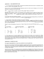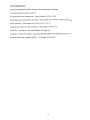
1
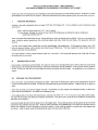
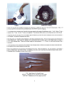
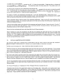
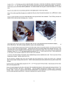
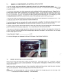
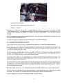
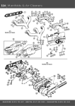
INSTALLATION INSTRUCTIONS - SPRITEIMIDGET FIVE SPEED OVERDRIVE TRANSMISSION CONVERSION KIT, MARK V Perform the shop work required to do this installation using good shop safety and workmanship practices. Reference to a quali ty SpritelMidget service manual will be required. Read these instructions fully before beginning work, then refer back as you work. I. PURCHASE MATERIALS Purchase a five-speed transmission from an August 1979 thru 1982 Datsun 210. You can identify a correct transmission using these factors : Both the input and output shafts are 25/32" with 18 splines. The serial number, stamped on a pad at the top, front of the bellhousing, just behind the engine cylinder head, should start with the letter "F ' . When you purchase the transmission also get: the gearshift lever, throw out bearing carrier and fork. If the car is to be used on the street, without the optional speedometer ratio correcting adapter and cable, obtain the stock Datsun 210 speedometer cable and housing. You may use the original slave cylinder that is on the SpritelMidget, with modification. Or Rivergate can furnish a new, CNC billet cut aluminum cylinder, with a stainless steel braid covered Teflon hose. This hose connects the master cylinder and slave cylinder without any extra connections. The original Datsun 210 slave cylinder cannot be used , as it is too small. It will cause pedal pressure to be too high and will cause the pressure plate to over-travel. II. PREPARATION OF CAR Remove engine, transmission and driveshaft. Be certain the center screw attaching the heater to the body above the center of the bellhousing does not protrude downward where it will hit the transmission during installation. If the car's frame is bent upward in the front, as many are, this will be an even tighter fit and the rear mount may also be tight. No modifications to the car body are required. ID. PREPARE THE TRANSMISSION Remove the starter, clutch, flywheel and engine rear plate. Inspect the two locator pins in the rear of the engine blOCK, one at the top center and one below the oil pump. Be sure they are present and in good, straight condition. Straighten and file or replace as needed . Remove the oil pump cover from the engine rear plate . Occasionally, on early engines, this may require heating, as these early engines had the cup soldered in . Be careful not to damage the cup. Bolt the adapter plate to the front ofthe transmission, using only one of the 5/16" x 2-114" cap screws at each side to hold in place. . The side with the counter sunk holes fits toward the transmission. This allows you to mark the spots to modify for oil pump cover and starter drive clearance. . Look back through the hole for the oil pump cover in the adapter plate. Using a felt tip marker, mark the portion of the front ofthe transmission that protrudes into this circle. Mark the starter protrusion on the bellhousing to cut a starter drive clearance hole as follows (not needed if you have converted to a gear drive starter). Center a felt tip marker in the starter hole in the adapter plate (See Photo). Mark the point inside the bellhousing that aligns with the center of this hole . 1 .... ~_.a.~v . _ _ ......, .,........_ , .... ~ -... .....OJ..,............ -- _ . • -- - - - - - - - - - -- - - - - - 0- --- --- - - 0 - - - - -- -- - ." .I . _ . _ _ Marking Modifications Completed Grind or file away the area marked for oil pump cover clearance to a depth of at least 5/16 " back into the transmission. (Hint If you use a rotary file in an electric drill, periodically spray with WD40 to prevent clogging.) To cut the starter drive clearance hole , first drill at the spot marked on the inside ofthe beIIhousing with a W' drill. Make a 2" hole centered on the W' hole. Use of a 2" hole saw is suggested. The aluminum drills easily, so even a cheap hole saw will do the job. Temporarily place the oil pump cover in the adapter plate and hold it up on the front of the transmission to be sure the clearance . cut is adequate. See photo of completed work above. Drill through the two, threaded, bottom boltholes in the Datsun transmission with a 3/8" bit to make clearance for the bolts that will be installed later. Clean up the five boltholes in the transmission that are used to attach it to the adapter plate by running a 11132" drill bit through them. These are the holes roughly at clock positions I , 2, 3, 10 and II , as view from the front of the transmission. A rib on the bottom of the transmission will interfere with the heads of the two bolts to be installed in the holes mentioned above . File or grind the rib to make clearance for these bolts. Remove the gearshift lever and check the pivot bushing for the lever. Most are found bad. You can purchase a new bushing from your Nissan dealer- Part #32855-HIOI0. The bushing at the lower end is rarely bad, but if needed is Nissan #32861-H7301. The gearshift lever is available as Nissan #3284 I-H85 10. TOP - Stock Datsun 210 Gearshift Lever MIDDLE - Modified Lever by Cut-down and Tap Threads BOTTOM - Modified Lever by Cut, Spacer and Weld 2 To modify lever as in the middle photo , cut the lever off 7-1/2" above the pivot bolthole. Grind the top down to a diameter of 5/16" for a length of I". Thread it to 5/16" NC and the original type knob or the Datsun knob will fit. This method works for all later Spridgets that have the soft gearshift boot. The bottom photo illustrates the lever modification that best fits the earlier cars that had the sheet metal cup around the gearshift lever. Saw the lever off 1-1/2" above the center of the pivot bolthole. Then saw off the lever 7" from the top end . Weld the W' x %" x I" spacer furnished with kits identified as the early cars between the two parts of the lever as illustrated. The I" dimension is between the two parts of the lever. Grind the comers rounded as shown . We suggest you install a new transmission rear housing seal. A new seal is furnished in the kit. It does not have the protective shield, which is not needed inside the Spridget transmission tunnel. It also eases installation of tile transmission into the chassis. This is the same seal as used at the front of the transmission, Nissan Part #32114-Y4000 . Find the protrusion along the back top slope of the transmission bellhousing. Grind or cut this off to ease installation of the engine/transmission assembly. We recommend sanding down the rib that runs down the top of the beIlhousing, for appearance and a little extra installation clearance. Locate the back-up light switch on the right side ofthe transmission just forward of the mount. Remove the switch. Coat the W' pipe plug in the kit with sealant and install here . Screw in only flush , not fully to the bottom of the hole. Back up lights will not be operational unless you wish to install a manual switch . Remove the throw-out bearing and carrier and release forks from the Datsun transmission. • Before installation, be certain the transmission will shift into all six positions. The input shaft may have to be turned while shifting. Occasionally installers have found transmissions which have been handled roughly which will not allow the shifter out of the gate it is in. This is caused by a shift rail sliding out of the neutral position due to an impact on the front or rear. If you find this problem, it can normally be solved by dropping the transmission several inches (on to a wood block please) . Try one end, then the other until gearshift locking is cleared. IV. INSTALL ADAPTER PLATE ON ENGINE .·TQe .aluminum adapter plate is furnished with a brushed finish on the edges, which is about all that shows after installation. I.liecause the adapter is machined from 6061 Aluminum, you can polish the edges to a high shine if you prefer. "" ." :: .' ~ : Carefully clean the oil pump cover . Sand or buff off any solder that might be on the rim . ., . . Install the oil pump cover into the aluminum adapter plate from the front side, just as it was in the original plate. If your oil pump cover is the type that solders on the backside of the engine plate, it may be too thin to clear the oil pump. This is especially likely if your engine is fitted with the later model oil pump. If there is inadequate clearance or if the cover is in bad condition, purchase a :.,,;.Rover # AEG553 oil pump cover. Mini Mania stocks these . :: ,' Put silicone gasket sealant around the inside of the oil pump hole in the adapter plate and around the edge of the oil pump cover. .·.,"P lace the cover into the plate from the front (opposite the countersunk bolt holes) . If time permits, place the plate on blocks, front ;';.:side up and place a weight in the cover to hold it firmly in place. Let the silicone harden overnight if possible . Wipe off excess , silicone on the front of the plate and cover, so that the adapter plate can lay completely flat on the back of the engine block. The new seal arrangement requires very precise placement of the seal, fore and aft. To get this precision requires that the adapter plate be installed onto the engine block using no gasket (they are too thick and vary in thickness too much) . Use the sealant furnished instead. For 948 and 1098 engines, see "Addendum for 948 & 1098 Engines With Rear Crankshaft Seal Kit" . Thoroughly clean the back of the engine block and the front of the adapter plate . Work quickly, so the sealant doesn 't begin • hardening before adapter plate is tightened down. With your finger, put a thin smear of sealant everywhere the gasket covered on the back of the block. Be especially careful to get full coverage around the oil pump cover. Quickly bolt on and torque down the adapter plate . Torque each bolt a second time to assure even tightening. Use the 5/16" x 1-1/4" flat head cap screws to attach the plate to the engine . In the hole at the left side, at about the 9:30 position, use the 5/16" x 1-3/4" cap screw so that the end of it can be used for the brace for the carburetor heat shield. Re-tighten the 9 screws twice to be sure all excess sealant is pushed out. Put silicone sealant into the groove around the backside of the oil pump cover. Clean the area around the rear main bearing and hole in the adapter plate to remove any oiliness . If any of the sealant around the oil pump cover extends into the area where the seal plate attaches, trim it blade. off flush with a sharp Using the sealant furnished , fill the area around the bolts to the right and left of the crankshaft. Then fill the gap between the bottom of the rear main cap and the adapter plate. See photo. Inject enough sealant into the gap to force it through so that a bit of it can be seen between the front edge of the adapter plate and the rear of the oil pan . Don 't put in enough sealant that it gets on the crankshaft flange . Place a 118" bead of sealant around each of the four bolt holes under where the seal plate attaches, fully circling each bolt hole. Then connect these with a 118" bead of sealant. Lubricate the lip of the seal and the outside of the crankshaft with grease. Slip the seal/seal plate over the crankshaft with the closed side of the seal toward the outside. Run in the four bolts, with washers and lockwashers - three 5116" x 1-1/2" fine thread around the top and one 5/16" xl " course thread at the bottom. Before tightening be sure the tension in the seal itself is allowed to center the seal on the crankshaft. The threads of the bolts holding the flywheel to the crankshaft flange must be installed with a sealer. This is to prevent oil from leaking past the threads . Locktite works fine for this. After the flywheel is installed, check to be sure the engine side of the flywheel isn 't in hard contact with the seal. Small spot contact with the rubber covering of the seal is OK. If there is hard contact between the flywheel and the seal, please contact Bill at Rivergate. Install the starter in the adapter plate using the two 3/8" x 1-1/4" NC cap screws with lock washers . Check clearance for the starter drive to the transmission case. Remove the pilot bushing from the hole in the back of the crankshaft and replace it with the special pilot bushing furnished. The kit is furnished with both a 5/8" and a W' pilot bushing. Very late engines will require the %" bushing. Drive it in up to the shoulder. (Hint A long 7/16" cap screw can be used as a bushing driver : run a nut all the way up on the threads , place bushing over the threads and tap the head of bolt.) Lubricate the bushing and re-install the flywheel. 4 V. MODIFY CLUTCH PRESSURE PLATE & INSTALL 1275cc CLUTCH The stock Spridget clutch pressure plate has a contact pad on the rear for the carbon throw out bearing originally fitted to these cars. It is no longer needed, as you will be installing a ball-type throw out bearing. The contact pads frequently rattles also, so it should be removed. To remove the contact pad, lay the clutch pressure plate on the workbench with the contact pad downward . Support the clutch pressure plate on boards , so that the contact pad is not contacting the surface. You will see that the contact pad is flared out over the clutch spring plate . With a cold chisel , knock the edges of the flange toward the center hole in the contact pad . Do this between each leaf of the spring plate. You should now be able to push the pad out of the spring plate. As an alternate, you can use a high-speed grinder (Dremell Tool) to grind away the comer of the contact pad inside, so that the pad drops off. This leaves the leafs of the clutch spring plate exposed for direct contact by the ball bearing throw out bearing you will use. This modification makes the 1275 's clutch match that of nearly all modem cars . Install and align the clutch disc furnished., with the stock pressure plate, as modified. Use the plastic alignment tool to assure proper disc alignment. The protruding hub of the clutch disc should be installed to the side away from the flywheel. Carefully measure the distance from the back side of the inner ends of the leafs of the clutch spring plate on the clutch pressure plate to the backside of the aluminum adapter plate . Use a straight edge across the clutch pressure plate . The clutch cover will hold the straight edge off the contact point on the ends of the leafs of the spring plate, so measure this distance and subtract it from the distance from the straight edge to the back of the adapter. (See Photo Below) Note this Spring Plate-to-Adapter figure for use later Spring Plate Leafs-to-Adapter: _ inches For 948 and 1098 engines, see Addendum for 948 and 1098 Engines: Clutch Release Modification. ., VI. MODIFY & MEASURE CLUTCH CLEARANCE Remove the old throw out bearing from the throw out bearing carrier. Stock length is about 1.65". Sometimes we find an incorrect throw-out bearing carrier in these transmissions. If a longer carrier is found, replace it with the correct 210 carrier, Nissan #3050I-H7500. Install the new throw out bearing on the carrier. (The curved surface installs away from the carrier.) Install the carrier and release forks onto the transmission. Hook the retracting spring in front of the ears on the carrier. With the throw out bearing pushed fully to the rear, measure the distance from a straight edge across the front edge of the bellhousing to the front face of the throw out bearing. (See Photo Below) 5 Bearing to front of bellhousing Spring Plate Leafs-to-Adapter distance (from Section V) Difference (Subtract) This difference must equal 118" (.125")or more . A preferable difference is about 3/16" (.187") - more is OK. This is a minimum on high revving or race cars . If this difference is not sufficient, the clutch can begin slipping before it is worn all the way to the rivet heads on the clutch facing. On standard 1275cc engines, this clearance will be adequate. If it is not more than 118" contact Rivergate. Before final installation, grease the throw out bearing slide tube . Also pack the groove inside the throw out bearing carrier, and lube the pivot ball for the clutch release fork. For 948 & 1098 engines, see Addendum for 948 and 1098 Engines: Clutch Release Modification. VII. ASSEMBLE TRANSMISSION TO ENGINE Look closely at how the rear mount in the kit is assembled (washer positions, etc.) Be sure final assembly matches this. Remove the top plate of the transmission rear mount and fasten it to the transmission with the countersunk screws furnished. The "U" shaped cutout mounts to the front. Leave off the bottom of the mount until the engine/transmission is in place in the car. This gives extra clearance for getting them in place. Bolt the transmission to the adapter plate on the rear of the engine. Use (5) 5/16" x 2-1/4 " caps crews with lock washers at the top and sides . At the bottom use (2) 5/16" x 1-112" cap screws with lock washers and flat washers. If an exhaust pipe brace or a ground strap are attached by these bolts, the flat washers should be omitted. Next install the slave cylinder. Use the original Spridget slave cylinder or the billet 7/8" cylinder available from Rivergate. Ifthe . original cylinder is used , bolt the slave cylinder adapter to the transmission using the Allen head metric cap screws furnished. The flat part of the adapter installs toward the rear. Note whether the front end of the cylinder interferes with the edge of the transmission (it generally will) . If so, grind clearance in the transmission. Lay the stock cylinder in place on the slave cylinder adapter, with the bleed screw upward. Grind the edge of the transmission so that when the cylinder lays flat on the adapter it will firml y contact the edge of the transmission. This is to provide extra bracing for the cylinder. Bolt on the cylinder with the 3/8" x 1-1/4" Button head cap screws and washers furnished in the kit with the pushrod furnished. The slave cylinder, at its top edge, will be very close to the car frame. To increase the clearance grind or file the top comer outside the bolt head . Cut it at about a 45° angle back enough that cutting just touches the head of the button head bolt. Install the modified yoke on the front of the Spridget driveshaft, Lube after installation 6 Before the engine/transmission assembly is installed in the car, inspect the clutch release linkage. Insure that the clutch release fork 's operating range is within the extreme ends of the hole where it passes thru the bellhousing. ,If it needs adjustment do this by adding or removing washers under the ball pivot for the clutch release fork. vrn. SPEEDOMETER (Skip this if you purchased Speedometer Adapter and Cable Kit.) If the Spridget is a street car and you didn't purchase the optional speedometer adapter and cable kit, you may wish to use the Datsun and the Spridget speedometer cable and housing to build a cable that will fit. Remove the connector from the top (speedometer) end of the Datsun and the Spridget cable housings. To reform the Spridget connector so that it will slide over the housing, carefully drive a round tapered punch into it from the housing end. Install the connector from the Spridget onto the top of the Datsun housing . With the bottom of the housing tightened into place on the transmission the cable should extend 3/8" beyond the end of the top connector. If not, remove the connector and shorten the housing to get the 3/8" . Crimp the connector into place. If you aren't certain your crimp is durable you may wish to reinforce it with a wrap of duct tape overlapping the connector and the end of the housing. Although the speedometer cable housing can be attached to the transmission working through the gearshift lever hole after the engine is installed, it is easier to use the following method. Attach the cable and housing to the transmission before installing in chassis . Form a loop extending about 8" to the rear of the transmission. Tape this loop to the rear seal area of the transmission to hold it in place during engine/transmission installation. Remove the tape after installation. After attaching the cable to the speedometer assure that the loop of cable in the driveshaft housing is far enough back to prevent the cable from contacting the exhaust at its front end. Fasten the cable into place to the body to the left of the transmission. Should the speedometer fail to operate, disconnect the cable and housing from the speedometer. Apply a coating of brazing (or solder) to the squared end of the speedometer chain, extending back about 114" from the tip . Grind or file this added material into a square shape approximately .124" across. Reinstall onto speedometer. .As a more acceptable alternative, Rivergate Restoration Products (RRP) offers a new custom speedometer cable and a ninety degree speedometer ratio adapter, that both connects the speedometer more easily, and corrects the speedometer reading for the size tires and differential ratio used. This optional speedometer cable and adapter kit can be installed after the engine and transmission have been installed. See order blank . IX. INSTALLATION IN CHASSIS Install the engine/transmission into the chassis as described in your workshop manual. Loosely install the front engine mounts. With the transmission in place in the tunnel, raise the transmission up off the rear crossmember. Now install the lower portion of the mount, just as it was furnished. Be sure the washers are in the same position as originally assembled . Leave the bolts that go up through the pad mounts a bit loose for now. Two defects are found on many Spridgets that can make installing the lower part of the mount a tight fit. The frame of a majority . of Spridgets is bent upward at the front, more frequently on the right side front frame . The area at the rear of the gearshift hole is often found bent downward (probably from people stepping on this area while climbing in over closed doors). If one of these conditions makes installation of the lower part of the mount too tight, remove the front mount bolts. Move the engine forward as much as possible. Put the rear mount into place, then put the engine back in the normal position. Install the original bolts up through the crossmember into the rear transmission mount and tighten. Next tighten the front engine mounts . Now center the transmission in the rear mount being certain the transmission isn 't touching the chassis anywhere. Tighten the transmission pad mount bolts. Install the furnished bolts in the sides of the rear mounts from inside the car with the self-locking nuts inside the tunnel. In some cars you may need to pry the side plates on the mount outwards a bit to allow the bolts to fit through them. (Hint: Tape the nuts in the wrench to make starting the threads easier.) 7 --n"-- . . . . ---------- ---- - - r -- - , - _ . - - ---- - - Install the driveshaft with the modified front yoke fitted . Grease the splines and seal surface of the yoke before installing. Install the gearshift lever in the transmission. Fill the transmission with gear lube. Valvoline Synthetic gearlube or some comparable top quality synthetic gearlube is strongly suggested for excellent shifting feel. Two and one quarter pints are required. Fill to the bottom of the fill hole on the left side of the transmission. X. PLUMBING CLUTCH HYDRAULICS If the original slave cylinder is to be re-used, re-route the clutch hydraulics original hydraulic tube to the left of the transmission and shorten as needed . It is suggested the tube be cut to length required and reflared. If a flaring tool is unavailable, the tube may be shortened by making a coil in it by wrapping it around a round object (a food can works) . If this method is used , you may choose to leave the hydraulics intact when the old transmission is removed, avoiding the need for bleeding the air out, as below. If the original slave cylinder is re-used, use the original tube nut. Fasten steel tubing to the frame and keep it away from exhaust piping. Bleed the clutch hydraulics. Use of a hydraulic bleeder pump is desirable for clutch bleeding. (Hint: In the absence of a power bleeder, several owners have improvised very successfully. Any source of low air pressure into the master cylinder reservoir will suffice. Some have used a manual air pump with a ball inflation needle inserted into the reservoir filler cap to provide the needed pressure, for example.) Adjust pushrod length to give some free travel at the clutch pedal. Assure clutch is releasing fully while the vehicle is still up on jack stands. Because of the possibility that wear in the pedal linkage can mimic clutch clearance, you should confirm freeplay by assuring that you can move the clutch operating lever away from the clutch cylinder pushrod. Finger pressure against the lever should be able to move it against the pressure of the spring inside the bellhousing. Generally W' to \12" of freeplay measured at this fork will be adequate. Be aware that the clutch pressure plate can be overtraveled . If the clutch releases when the pedal is part way down but then seems to re-engage at full pedal down, it is being overtraveled. Add freeplay until this condition disappears. To add more freeplav. the nuts on the pushrod will be moved toward the front of the car. Install gearshift boot and liner being certain it doesn 't put pressure on the gearshift lever in any position. If the gearshift linkage interferes at the left side, loosen the chassis-to-transmission mount bolts and the bolts through the transmission mount pads . Force the transmission fully to the right side and retighten. It may be difficult to prevent the early Sprite metal shifter cover from interfering with the shift lever. It so, use of the later model shift boot is suggested. XL ROAD TEST You are now ready to road test the installation. Note that clutch feel may be different than stock. If speedometer is used , check it for correct reading. If the speedometer error is unacceptably high, consider use of the speedometer angle ratio adapter and cable kit available from Rivergate to correct the reading. After a break-in period for the clutch disc, the clutch slave cylinder pushrod may require a re-adjustment to maintain free travel at the clutch pedal. With proper maintenance of free travel the clutch can be expected to last much longer than the stock setup, due to the synchronized low gear and improved clutch disc quality. XII. ASSISTANCE AVAILABLE Rivergate offers products and services to make your installation of the 5-speed conversion kit easier and better. See the order blank. 1. Speedometer angle ratio adapter and cable kit. Custom geared to correct the speedometer reading to be accurate with the tires and differential ratio you use. Includes a new custom cable . Makes installation easy and neat. ($125 .00) 2. Labor to shorten and re-thread your gearshift lever as required for installation. ($14.00) If you need assistance in installation of the kit, call Bill or Will at 423-332-2030, 9 AM to 5 PM Eastern time . Please call only after having carefully read the instructions and studying the parts involved. This way, we can have an informed discussion ofyour problem. NOTE: Cars with Datsun transmissions installed should not be flat-towed without disconnecting the driveshaft. 8 ADDEND.UM 1: FOR COMPETITION CARS: I. For car fitted with Tilton racing type clutch : The clutch disc that should be used with the Datsun 210 transmission and the Tilton 7-114" clutch is Tilton part number 364185-Q-A-18.. Because there are a variety of flywheels and release mechanisms used with the Tilton clutch on Spridgets, you will not use the instructions on modifying the clutch release linkage . After the flywheel and clutch are installed , measure the "Pad-to-Adapter" distance as in Section IV. With clutch release mechanism mounted in the transmission, and fully retracted (to the rear), measure the "Bearing to front of bellhousing" as detailed in Section VI. Assure that the "Bearing to front of bellhousing" exceeds the "Spring Plate Leafs-toAdapter" distance by about .1" to assure adequate clutch clearance . Modify as required to get this clearance if it doesn 't have .1" or above. If stock Datsun clutch release mechanism is retained, check to see if the tube that the throwout bearing slides on will interfere with the clutch hub. If it will, shorten it as required as in instructions at the end of Section V. II. When the Datsun 5 speed overdrive transmission is to be used in competition, we suggest the car be fitted with one step lower ratio differential than was used with the non-overdrive transmission. For example, it if previously used a 4.22:1 ratio, change to the 4.55:1 ratio. This allows use ofthe top three gears only on most race tracks . This is advantageous because these are the closest ratios in the Datsun transmission. Column #1 under each transmission is the gear ratio. Column #2 under each is the percent RPM reduction upon upshift to that gear . Stock Sprite Ribcase .Gear 1 2 Levland Close Ratio Ribcase 1 2 Gear 1 2 3 4 1 2 3 4 3.2 1.916 1.357 1.0 40.1% 29.2% 26.3% 2.573 1.722 1.255 1.0 Datsun 210 5-Speed Gear 1 2 1 2 3 4 5 33.1% 27.1% 20.3% 3.513 2.17 1.378 1.0 .821 38.2% 36.5% 27.4% 18.9% III. If the 5-speed race car is ever used in competition where rules require only a four speed, it can be converted easily. Shifting this transmission into low gear slides the shift: rail into a pocket at the right, top of the extension case. Drill and tap this pocket from the rear end. Run in a screw, with a jam nut, that will block travel into low gear . To convert back to five speeds, back out the screw enough to allow engagement of low gear, and retighten the jam nut. Changing between 4 and 5 speeds can be done with the transmission in the car. ADDENDUM 2: ENGINE OIL LEAKS H the engine is disassembled here are some extra precautions you can take against leaks. If the engine is an early model with the felt front crankshaft seal, replace the timing chain cover with the later model with the more effective seal. The cover from a 1275, with the crankshaft ventilation system is best as it helps relieve crankcase pressure . If crankcase pressure is high a leak somewhere is almost inevitable. Be certain crankshaft ventilation, including a valve cover vent, is as open as you can make it. Inspect the oil pan carefully. If the attaching screws have previously been overtightened, the bolt flange will be bent upward around the bolt holes. Carefully tap them back down level using the round end ofa ballpeen hammer. Inspect the retainers for the seals on the front and rear of the oil pan. These are sometimes found to be cracked or partially detached from the pan . Braze to repair or replace the pan if they are faulty. 9 The labyrinth seal at the back of the rear main bearing is a source of leaks. Before the rear main bearing cap is installed, put a light smear of gasket sealant on the portion of the cap which extends past the back of the block to prevent leak through this unsealed surface. Be sure the top half of the seal (attached with three bolts) is pushed down close to the crankshaft before tightening. When installing the oil pan, use generous amounts of sealant, especially at the comers where the main bearing caps adjoin the block. The oil pump cavity is a frequent source of oil leaks, often blamed on the crankshaft. The cavity is fully exposed to the crankcase. The leaks result because the original engine rear plate is too thin in the area between the oil pump and the crankshaft to properly compress a gasket. The iron plate on the 1275cc engines is frequentl y cracked in this area, adding to the leaking problem. The Rivergate adapter plate is strong enough to eliminate the possible leaks there, if the oil pump cover is carefully sealed into the adapter plate. (Revised and Printed July 2003) 10 PARTS REFERENCES: Retain these instructions for future references when maintaining your Spridget. For replacement parts use parts as follows : Universal joint for new Rivergate yoke - Neapco Numbers 1-0300 & 1-0248 Rear transmission seal (front seal is the same) - Nissan number 32114-Y4000, or 30x45x1O metric seal Throw out bearing - NSK number TK40-14AU3, BCA # TOI7l0 Clutch disc for Tilton race clutch installation - Tilton number 364185-Q-A-18 Clutch disc - 1098 engines - use standard Datsun 210 clutch disc. Clutch disc - 948 and 1275 engines - special disc RRP part number 30303 for 948 and 30301 for 1275 Seal for Rivergate Rear Crankshaft Seal Kit - TCM number 78xl00xl0TC 11 ORDER FORM Name -'- Phone _ Address _ Car used for: Street __ Competition __ Show __ Car Make Model FIVE SPEED OPTIONS: Year AMOUNT : Labor to shorten and re-thread your gearshift lever as required for installation (#30420)------------- $ 14.00 Slave Cylinder and Hose -7/8" (#30447) ------------- ---------------------------------------------Includes Stainless Steel Braid Hose and fittings. $ 89.00 Clutch Disc - To change sizes of engine (948, 1098 or 1275) only a change of clutch disc is required. $ 89.00 For 948 engines order #30303 ---------------- --------------------------------------------------$ 89.00 For 1098 engines order #30302 ---------------------------------------------------------------For 1275 engines order #3030 1 ------------------------------------------------- -----------$ 89.00 Speedometer Adapter Kit (#30040) ------------------------------------------------------------------ $125.00 Includes 90 degree speedometer ratio adapter for transmission and custom made speedometer cable. Corrects reading and connects to original speedometer . (Optional Item. Information on adapting a Datsun cable is included in 5-speed kit instructions, but speedometer reading may differ from actual speed.) To order we need: Tire Size Differential Ratio: Rolling circumference of rear tires ** :1 inches **To measure : (1) Make a chalk mark on the side of tire at the exact bottom . (2) Mark the pavement in line with this mark on the tire. (3) Roll vehicle until tire turns one revolution and mark on tire is at bottom again, (4) Mark pavement exactly in line with mark on tire (5) Measure the distance between marks on pavement. MERCHAND ISE TOTAL -------------------------------------------------------------~-------------------------------- In Tennessee add 7.750/0 Sales Tax ------------- ------------------------------------------------------------------------SHIPPING CHARGES -------------------------------------------------------------------------------------------------TOTAL ENCLOSED Rivergate Restoration Products 233-A Industrial Park Drive Soddy-Daisy, TN 37379 423-332-2030 423-332-6 914 - Fax E-Mail: [email protected] \vww.rivergate5speed .com 12 8.00