1
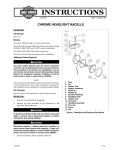
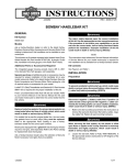
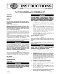
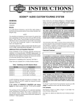
-J05522
REV. 2015-05-12
BOOM! AUDIO CRUISER AMP AND SPEAKER KITS - HANDLEBAR
MOUNT
Electrical Contact Lubricant (Part No. 99861-02) or equivalent
is required after battery cable disconnection. This item is
available from a Harley-Davidson dealer.
GENERAL
Kit Numbers
76262-08A, 76320-08A
Models
For model fitment information, see the P&A retail catalog or
the Parts and Accessories section of www.harley-davidson.com
(English only).
Installation Requirements
The following models require separate purchase of an Electrical
Connection Kit (Part No. 72673-11):
•
2011 and later Softail® models
•
2012 and later Dyna® FLD Switchback models
•
2014 Sportster models
The following models require separate purchase of a Speaker
and Amplifier Relay Kit (Part No. 69200397):
•
2000-2010 Softail models
•
2010-2011 FXDWG (Dyna Wide Glide®) models
•
2004-2013 XL Sportster® models
•
1999-2013 Road King® models
The following models require separate purchase of Kit (Part
No. 69200722):
•
2014 and later Road King models
Connection to a portable audio player (purchased separately)
with a 1/8-inch (3.5 mm) stereo output (headphone jack or
audio line out) is required.
NOTES
A Boom! Audio Tank Pouch (Part No. 91003-10) can be used
to secure a solid-state portable audio player.
DO NOT secure a portable audio player with a hard drive
memory on or to the vehicle.
For best sound quality, an installed windshield is recommended.
An UltraTorch UT-100 (Part No. HD-39969), Robinair Heat
Gun (Part No. HD-25070) with Heatshrink Attachment (Part
No. HD-41183), or other suitable radiant heating device is
required for the proper installation of this kit.
-J05522
The rider's safety depends upon the correct installation
of this kit. Use the appropriate service manual procedures.
If the procedure is not within your capabilities or you do
not have the correct tools, have a Harley-Davidson dealer
perform the installation. Improper installation of this kit
could result in death or serious injury. (00333a)
NOTE
This instruction sheet refers to service manual information. A
service manual for this year/model motorcycle is required for
this installation and is available from a Harley-Davidson dealer.
Electrical Overload
It is possible to overload your vehicle's charging system
by adding too many electrical accessories. If the combined
electrical accessories operating at any one time consume
more electrical current than the vehicle's charging system
can produce, the electrical consumption can discharge
the battery and cause damage to the vehicle's electrical
system. See an authorized Harley-Davidson dealer for
advice about the amount of current consumed by additional electrical accessories or for necessary wiring
changes. (00211c)
When installing any electrical accessory, be certain not
to exceed the maximum amperage rating of the fuse or
circuit breaker protecting the affected circuit being modified. Exceeding the maximum amperage can lead to electrical failures, which could result in death or serious injury.
(00310a)
The Amp and Speaker Kit requires up to 4.0 A additional current from the electrical system.
Kit Contents
See Figure 7 and Table 1.
Many Harley-Davidson® Parts & Accessories are made of plastics and metals which can be recycled.
Please dispose of materials responsibly.
1 of 10
4.
PREPARATION
NOTE
For 2007 and later vehicles equipped with security siren:
•
Verify that the Hands-Free Fob is present.
•
Turn the ignition key switch to IGNITION.
For EFI Models:
Turn the fuel supply valve OFF. Remove the fuel line from
the valve.
For ALL models:
When servicing the fuel system, do not smoke or allow
open flame or sparks in the vicinity. Gasoline is extremely
flammable and highly explosive, which could result in
death or serious injury. (00330a)
5.
To prevent spray of fuel, purge system of high-pressure
fuel before supply line is disconnected. Gasoline is
extremely flammable and highly explosive, which could
result in death or serious injury. (00275a)
See the service manual. Remove the instrument console
(if equipped) from the fuel tank.
6.
See the correct section (Carbureted or EFI Engine) of the
service manual for fuel tank removal instructions.
See the service manual. Purge and disconnect fuel supply line.
7.
For Road King models only: Remove the handlebar
cover from the vehicle. Separate the left and right nacelle
halves. Remove the headlamp assembly per service
manual instructions.
For ALL Vehicles With Main Fuse:
INSTALLATION
To prevent accidental vehicle start-up, which could cause
death or serious injury, remove main fuse before proceeding. (00251b)
1.
See the service manual. Remove the main fuse and the
seat. Retain the seat and all mounting hardware.
Amplifier and Bracket Installation
1.
See Figure 7. Select two screws (6) and the correct amplifier mounting bracket (item 7 or 8) from the kit.
•
For Road King and XL Sportster models: select bracket
(7).
•
For Dyna and Softail models: select bracket (8).
For ALL Vehicles With Main Circuit Breaker:
NOTE
To prevent accidental vehicle start-up, which could cause
death or serious injury, disconnect negative (-) battery
cable before proceeding. (00048a)
The wire exiting the amplifier must face downward.
2.
See Figure 1. Install the amplifier (5, part of the wire harness assembly) to the bracket with the screws (6), and
tighten to 65 in-lbs (7.4 Nm).
3.
If this kit is being installed on a vehicle with an engine
guard (except for Road King models), use the engine
guard hardware to secure the amplifier bracket.
NOTE
For 2004 and later XL Sportster models, the negative battery
cable is most easily disconnected at the engine crankcase.
1.
2.
3.
See the service manual. Remove the seat and disconnect
the negative (black) battery cable from the negative (-)
battery terminal. Retain all seat mounting hardware.
For ALL models: Turn the ignition key switch OFF if not
already done.
See the service manual or instructions in the accessory
kit. Remove windshield. Make sure to protect the windshield from scratches during removal and installation, and
while off the vehicle.
If NOT being installed with an engine guard, use hardware from the kit to secure the amplifier bracket. See
Figure 7.
•
For XL Sportster models: Select two screws (9) from
the kit.
•
For Dyna models: Select one screw (9) and one locknut
(10) from the kit.
•
For Softail models: Select screw (11) and locknut (12)
from the kit.
•
For Road King models: Select two screws (15), two
washers (13) and two locknuts (14) from the kit.
For Carbureted Models:
Gasoline can drain from the carburetor fuel line when
disconnected from fuel valve fitting. Gasoline is extremely
flammable and highly explosive, which could result in
death or serious injury. Wipe up spilled fuel immediately
and dispose of rags in a suitable manner. (00256a)
-J05522
2 of 10
is06077
9
7
8
9
10
5
5
6
XL 1
FLHR
13
2
FLD/FXDWG
3 FLST/C/F/FB/N
FXST/B/C/D
4
7
14
6
15
6
6
12
8
5
8
6
11
5
12
FXCW/C, FXS
1. Sportster (XL) installation
2. Dyna (FLD/FXDWG) installation
3. Softail (FLST/C/F/FB/N, FXST/B/C/D) and Rocker
(FXCW/C) installation
4. Road King (FLHR) installation
5. Amplifier
6. TORX button head screw, 1/4-20 x 0.62 inch (16
mm) (2)
7. Amplifier mounting bracket (XL Sportster/FLHR)
8. Amplifier mounting bracket (Dyna/Softail)
9.
10.
11.
12.
13.
14.
15.
11
Hex head screw, 3/8-16 x 0.75 inch (19 mm) (2)
Hex locknut, 3/8-16 (2)
Hex head screw, 5/16-18 x 0.75 inch (19 mm)
Hex locknut, 5/16-18
Fender washer (2)
Hex locknut, 1/4-20 (2) (2013 and earlier models)
TORX button head screw, 1/4-20 x 0.75 inch (19
mm) (2)
Figure 1. Amplifier and Bracket Installation
4.
See Figure 1. Install the amplifier and bracket to the frame
crossmember between the front down tubes as shown.
2.
Obtain the hand control bracket (3), two spacers (2), two
screws (6) and:
•
For XL Sportster models: Tighten the fasteners to 3033 ft-lbs (40.7-44.8 Nm).
•
for 2004 and later XL Sportster models: two screws (4)
from the kit.
•
For Dyna models: Tighten the fasteners to 30-33 ft-lbs
(40.7-44.8 Nm).
•
for ALL OTHER models: two screws (4) from the kit.
3.
•
For Softail models (except Rocker™): The amplifier
bracket installs behind the crossbar. Tighten the fasteners
to 19 ft-lbs (25.8 Nm).
Route the hand control (5) wire harness through the center
of the hand control bracket (3) as shown.
4.
Position the spacers into the clamp mounting cutouts.
Place the hand control bracket onto the spacers. Install
the clamp, spacers and bracket to the brake master cylinder with the two screws. Tighten the screws to:
•
for 2004 and later XL Sportster models: 108-132 in-lbs
(12.2-14.9 Nm).
•
for ALL OTHER models: 60-80 in-lbs (6.8-9.1 Nm).
5.
Install the hand control (5, part of the wire harness
assembly) to the bracket with screws (6). Tighten securely.
6.
Use cable straps from the electrical hardware pack to
secure the wiring to the existing hand control wiring.
•
For Rocker models: The amplifier bracket installs in front
of the crossbar. Tighten the fasteners to 19 ft-lbs (25.8
Nm).
•
For Road King models: Tighten the fasteners to 65 inlbs (7.4 Nm).
Hand Control and Bracket Installation
1.
See Figure 2. Remove the front brake lever clamp screws
from the vehicle. Remove and retain the clamp (1). The
screws can be discarded.
-J05522
3 of 10
is06076
2
4
1
1.
2.
3.
4.
5.
6.
See Figure 3. Obtain the following items from the kit:
•
speaker pod assembly (1)
•
two upper handlebar clamps (2)
•
two lower handlebar clamps (3)
•
four spacers (4)
•
four screws (5)
•
two screws (6)
If mounting to 1-1/4 inch (31.8 mm) diameter handlebars, the
spacers can be discarded.
3
6
1.
5
Front brake lever clamp
Spacer (2)
Hand control bracket
Hex socket button head screw (2)
Speaker/amplifier hand control
#10-24 Phillips screw (2)
Figure 2. Hand Control and Bracket Installation
Speaker Installation
NOTE
Insert the spacers inside the clamps for vehicles with 1.0 inch
(25.4 mm) diameter handlebars. Make sure the spacers seat
in the recesses (7) inside the clamps.
2.
Secure each speaker clamp pair to the handlebar with two
screws (5), and tighten to 60 in-lbs (6.8 Nm)
3.
Position a speaker pod, oriented with the speaker grille
facing the rider as directly as possible, onto each upper
clamp. Secure each speaker pod to the upper clamp with
a hex head screw (6). Tighten the screw to 12-14 ft-lbs
(16.3-19.0 Nm).
NOTES
Test-fit to determine the desired location for the speakers on
the handlebar.
is06078
1
Both speaker pods are wired together with a single electrical
connector. Do not separate for test-fit or installation.
•
The speaker clamps shall be positioned so the speakers
are above the bar. The speakers should appear symmetrical to the left and right of the handlebar clamp, and
should be placed as close to the center of the motorcycle
as possible.
•
The upper clamps can be positioned so the speaker
mounts are in front of or behind the bar.
•
If the vehicle is normally equipped with a windshield, locate
the clamps on the middle straight section of the bar so the
speaker housings will clear the windshield.
•
•
The Bar & Shield trim badges on the speaker faces can
be rotated to the desired orientation after installation by
pushing with two fingers and turning.
Check to be sure speaker and clamp positioning will not
interfere with steering function, control operation or visibility
of instruments.
7
6
2
7
4
4
3
1.
2.
3.
4.
5.
6.
7.
5
Speaker pod (2)
Upper handlebar clamp (2)
Lower handlebar clamp (2)
Spacer (4)
TORX screw (4)
Hex head screw (2)
Recess inside clamp (4)
Figure 3. Handlebar-Mounted Speaker Installation
-J05522
4 of 10
1.
WIRE HARNESS CONNECTION
Install the Electrical Connection Harness:
a.
See Figure 4. Locate the Digital Technician connector
[91A] (Item 1, a gray six-way Deutsch connector with
a rubber boot) under the seat. Place the Electrical
Connection Harness (2) at the Digital Technician
connector, but DO NOT connect them now.
b.
Route the speaker and amplifier harness (3) wires
over to the Electrical Connection Harness. Cut the
speaker and amplifier wires to a suitable length to
easily reach the sealed splice connectors (4 and 5)
on the Electrical Connection Harness.
c.
Avoid directing heat toward any fuel system component.
Extreme heat can cause fuel ignition/explosion resulting
in death or serious injury.
Splice both the red and the orange/white speaker and
amplifier wires to the red/yellow wire sealed splice
connector (4) in the Electrical Connection Harness.
d.
Avoid directing heat toward any electrical system component other than the connectors on which heat shrink
work is being performed.
Splice the black speaker and amplifier wire to the
black wire sealed splice connector (5) in the Electrical
Connection Harness.
e.
Use a heat gun or suitable radiant-heating device to
shrink the connector to the wires.
Always keep hands away from tool tip area and heat shrink
attachment.
f.
Use the heat gun or heating device to seal the open
end of the sealed splice connector (6) on the red/blue
wires in the Electrical Connection Harness.
g.
Pull the rubber boot out from the gray Digital Technician pin connector [91A]. Cut the boot off the wires.
For 2011 and later Softail models: Proceed to the next section.
h.
Connect the socket housing of the Electrical Connection Harness to connector [91A].
For 2014 and later Touring models: Proceed to THAT section.
i.
Insert the rubber boot into the open pin connector of
the Electrical Connection Harness.
For ALL OTHER models: Proceed to THAT section.
j.
Proceed to WIRE ROUTING.
General
Splicing of wire leads is necessary in the installation of the
speaker and amplifier kit to the motorcycle. Find the instructions
for a specific model in the sections that follow, and refer to the
service manual appendix for proper wire splicing procedures.
Be sure to follow manufacturer's instructions when using
the UltraTorch UT-100 or any other radiant heating device.
Failure to follow manufacturer's instructions can cause a
fire, which could result in death or serious injury. (00335a)
•
•
•
For 2014 and later Sportster models: Proceed to the next
section.
For 2012 and later Dyna models: Proceed to the next section.
For 2012 and Later Dyna, 2011 and Later Softail, and
2014 and Later Sportster Models
For 2014 and later Road King Models
Electrical connectors are identified in the service manual by
the number and letter shown here within brackets.
NOTE
Requires separate purchase of Electrical Connection Kit (Part
No. 72673-11).
BK
is07122
R
O/W
O/W
3
6
5
Use Y-connector 70264-94A for additional 4-way connectors.
If accessory wires have already been spliced to 69200722 in
a prior install, it is possible to splice in up to three accessories.
BK
4
1
2
R/Y
R/BE
BK
[91A]
6
5
4
3
2
1
1.
2.
3.
4.
5.
6.
R
6
5
4
3
2
1
R/BE
R/Y
BE/R
R/BE
R/Y
BE/R
W/BK
W/BK
BK
W/R
BK
W/R
1.
Locate the gray 8-way pin-side Molex connector [4A] under
the left side cover. It is located in the electrical caddy, directly over the Digital Tech Connector [91A]. If wire harness
(part no. 69200722) is already connected to connector [4]
from a prior install, then disconnect it.
2.
Route the harness from the Electrical Connection Kit
according to the instructions in that kit.
6
5
4
3
2
1
Digital Technician connector [91A]
Electrical connection harness
Speaker and amplifier harness
Red/yellow wire sealed splice connector
Black wire sealed splice connector
Red/blue wire sealed splice connector
Figure 4. Wiring Diagram, Speaker/Amplifier Harness to
Electrical Connection Harness
-J05522
NOTE
Wire harness (part no. 69200722) may have been previously
installed during the installation of another accessory. If it is
already installed, it is not necessary to replace it.
NOTE
Do not connect the 8-way connectors now.
3.
The electrical connections will be made to 2 (or 3) of the
sealed cap ends of the Electrical Connection kit.
4.
See the service manual for detailed instructions on sealed
splice connections.
5 of 10
If wire harness (part no. 69200722) was previously spliced,
cut off existing splices. See Figure 4 for multiple splice
configuration.
is07117a
Clip the cap off the black wire, strip back, crimp &
seal to BLACK wire of the wire harness of (this kit).
b.
Clip the cap off the violet/blue wire of 69200723, strip
back, crimp & seal to orange/white and the RED wire
of the wire harness of (this kit).
c.
O/W
10
R
If wire harness (part no. 69200722) was spliced in a prior
install, make sure the 8-way Molex connector is disconnected from vehicle connector [4].
a.
[B+]
9
5
BK
R
O/W
[7A]
8
R
[7B]
3
5A
R
7
R
[87]
2
O/W
6
R
DO NOT REMOVE the sealed cap from the RED wireit is not used.
GRND
4
[85]
5
[86]
BK
O/W
2
[30]
1
1
3
R
5.
Remove the weather cap from connector [4A] and connect
the 8-way connectors together.
1.
2.
3.
4.
5.
6.
7.
8.
9.
10.
For ALL OTHER Models
NOTE
Requires separate purchase of Speaker and Amplifier Relay
Service Kit (Part No. 69200397).
1.
Route the speaker and amplifier harness to the area under
the seat.
2.
See Figure 7. Get the electrical hardware pack (22) from
THIS kit.
3.
Select the in-line fuse holder (23) and one blue sealed
splice connector (28) from the hardware pack.
4.
Get the relay kit (Part No. 69200397), purchased separately. Refer to the instructions that follow BELOW for
relay installation.
5.
See Figure 5. Find a suitable location under the seat for
the relay (1), so that the terminals face down or horizontally. The terminals should not face upward.
6.
Cut the orange/white wire (2) in the main electrical
harness near the rear lighting connector [7].
7.
See the service manual appendix. Use a suitable radiantheating device to splice and seal the two cut orange/white
wires to the sealed splice connector (4) on the
orange/white wire (3) from relay terminal 2.
Relay
Orange/white wire in main electrical harness
Orange/white wire from relay terminal 2
Sealed splice connector on terminal 2 wire
Speaker/amplifier harness
Sealed splice connector on terminal 3 wire
Sealed splice connector on terminal 5 wire
In-line fuse holder
12V adapter wire (B+ connector)
Sealed splice connector from kit
Figure 5. Wiring Diagram, Speaker/Amplifier Harness to
Relay
8.
Cut the speaker and amplifier harness (5) red and
orange/white wires to a suitable length to easily reach the
sealed splice connectors on the relay. Splice and seal the
red and orange/white wires to the sealed splice connector
(6) on the red wire of relay terminal 3.
9.
Select the sealed splice connector (7) on the free end of
the red wire coming from relay terminal 5. Splice the red
wire on one end of the in-line fuse holder (8) to the red
wire of relay terminal 5.
10. Splice the opposite end of the in-line fuse holder to the
12V adapter wire (9) with the blue sealed splice connector
(10) from the hardware pack.
11. See Figure 6. Locate the B+ (battery positive) connector
(1) on the main electrical harness under the seat (a red
wire with an unused gray connector). Remove the cover
(2) from the B+ connector.
12. Connect the red 12V adapter wire connector on the wire
harness assembly to the B+ connector.
is03793
1
2
1. B+ connector
2. Cover
Figure 6. B+ Connector
-J05522
6 of 10
13. See Figure 7. Select a ring terminal from the electrical
hardware pack.
7.
Clean with a mixture of 50 percent isopropyl alcohol and
50 percent distilled water. Allow to dry completely.
•
Dyna Wide Glide models: use the 5/16 inch (7.9 mm) ID
terminal (27).
8.
•
All models EXCEPT Dyna Wide Glide: use the 1/4 inch
(6.4 mm) ID terminal (26).
Remove the liner from the adhesive backing of the clip.
Carefully position the clip to the upper triple clamp or
nacelle, and press firmly into place. Hold the clip in position
with steady pressure for a few seconds.
9.
Secure the 3.5 mm connector from the hand control to the
clip.
14. Select the free end of the black wire in the speaker and
amplifier harness assembly. Cut the black wire to easily
reach the location of the vehicle ground. Crimp the ring
terminal to the black wire per the instructions in the service
manual.
RETURN TO SERVICE
1.
15. Select the black wire from relay terminal 1. Attach both
black wire ring terminals to the vehicle ground stud.
For 2011 and later Softail models only: Install the split
conduit (30) over the brake line where it passes closest
to the amplifier.
WIRE ROUTING
1.
For Road King models only: See the service manual
and assemble the left and right nacelle halves. Assemble
the handlebar cover to the vehicle.
Use cable straps (29) from the electrical hardware pack
to secure the amplifier wiring to the frame downtube.
2.
For Road King models: Use the existing P-clamp on the
left side of the frame near the steering head to secure the
amplifier wiring.
ALL models: See the correct section (Carbureted or EFI
Engine) of the service manual for fuel tank installation
instructions.
3.
Install the windshield (if equipped) to the vehicle per the
instructions in the service manual or accessory kit. Make
sure to protect the windshield and speaker pods from
scratches during installation.
Be sure that steering is smooth and free without interference. Interference with steering could result in loss of
vehicle control and death or serious injury. (00371a)
•
Make sure the wires do not restrict steering movement.
•
Route the wires along the frame backbone under the tank.
Tie to existing wire bundles with cable straps, especially
at any change in direction.
2.
Coil excess wire under the fuel tank, inside the nacelle or
under the handlebar clamp where it does not interfere with
steering function. Install the 5A fuse (24) in the in-line fuse
holder on the red wire.
3.
Lay the harness along the frame backbone, under the fuel
tank and seat, with the four-way connector positioned near
the steering head.
Be sure that steering is smooth and free without interference. Interference with steering could result in loss of
vehicle control and death or serious injury. (00371a)
4.
NOTE
Verify that the ignition switch is in the OFF position before
installing the main fuse or attaching the battery cable.
5.
Connect the four-way connector from the speaker pods
to the four way connector on the wire harness assembly.
5.
See Figure 7.The 3.5 mm connector from the hand control
can be secured to the handlebar with cable straps or
secured to the upper triple clamp or nacelle with the
adhesive-backed clip (21) from the kit. If using the clip:
•
•
NOTES
Ambient temperature should be at least 60 °F (16 °C) for
proper adhesion of the clip to the vehicle.
Allow AT LEAST 24 hours after applying the clip before
exposing the area to vigorous washing, strong water spray
or extreme weather.
Models with main fuse: See the service manual and
install the main fuse.
Models with main circuit breaker:
The connector may be placed inside the nacelle (Road
King models) or handlebar clamp.
4.
Make sure the speaker pods do not interfere with steering
function, controls operation or visibility of instruments.
a.
For ALL models except XL Sportster: See the
service manual and attach the negative battery cable.
Apply a light coat of petroleum jelly or corrosion
retardant material to battery terminals.
b.
For XL Sportster models only: See the service
manual, and connect the negative battery cable at
the engine crankcase.
After installing seat, pull upward on seat to be sure it is
locked in position. While riding, a loose seat can shift
causing loss of control, which could result in death or
serious injury. (00070b)
6.
See the service manual and install the seat.
•
The adhesive bond will increase to maximum strength
after about 72 hours at normal room temperature.
7.
Turn the ignition switch to IGNITION, but do not start the
motorcycle.
6.
Test-fit the clip to the upper triple clamp or nacelle before
installation. Do not remove the liner until ready to apply
the clip.
8.
Connect the audio input cable (20) from the kit to the
female 3.5 mm stereo connector from the hand control.
-J05522
7 of 10
9.
Connect the free end of the audio input cable to the
headphone jack (or line out) of the portable audio player
(purchased separately).
a.
Turn on the audio player. Set the player volume output
at 75-80 percent of maximum.
b.
Turn on the amp using the hand control on/off pushbutton switch. The switch illuminates when power is
on.
c.
Use the handlebar control to adjust the volume level.
VOL+ increases the volume. VOL- decreases the
-J05522
volume.
d.
The amp and speakers can be operated with the
ignition switch in either the "ACC" or "IGNITION"
position.
NOTE
DO NOT secure an audio player with a hard drive memory
on or to the vehicle. Vehicle vibration can permanently damage
the device.
Refer to the audio player instructions to determine if the device
to be used has a hard drive memory.
8 of 10
SERVICE PARTS
17
is06088a
16
31
18
31
1
19
32
9
5
32
14
7
2
13
15
5
4
22
3
6
15
9
12
23
24
25
10
29
27
8
26
20
28
9
11
30
5
21
Figure 7. Service Parts, Handlebar-Mounted Speaker and Amplifier Kits
Table 1. Service Parts
Kit
Item
Kit 76262-08A
Handlebar-Mounted
Speaker/Amplifier
Kit (Chrome)
1
Speaker pod assembly (chrome)(includes two of item 31, connected)
Not sold separately
2
Speaker clamp, handlebar (lower, chrome)(2)
76558-08
3
Speaker clamp, handlebar (upper, chrome)(2)
76559-08
Kit 76320-08A
Handlebar-Mounted
Speaker/Amplifier
Kit (Black)
1
Speaker pod assembly (black)(includes two of item 31, connected)
Not sold separately
2
Speaker clamp, handlebar (lower, black)(2)
76090-08
3
Speaker clamp, handlebar (upper, black)(2)
76089-08
-J05522
Description (Quantity)
Part Number
9 of 10
Table 1. Service Parts
Kit
Items common
to BOTH kits
Item
Description (Quantity)
Part Number
4
Spacer, handlebar speaker housing (4)
Not sold separately
5
Amplifier/hand control/wire harness assembly
70220-08
6
Screw, button head, TORX, 1/4-20 x 0.62 inch (16 mm) long (2)
924
7
Bracket, amplifier mounting (Sportster and Road King models)
76551-08A
8
Bracket, amplifier mounting (Dyna and Softail models)
Not sold separately
9
Cap screw, hex head, 3/8-16 x 0.75 inch (19 mm) long (4)
4713W
10
Hex locknut, 3/8-16 Nylock
7778
11
Cap screw, hex head, 5/16-18 x 0.75 inch (19 mm) long
3987
12
Hex locknut, 5/16-18 Nylock
7739
13
Fender washer, M6 (2)
Not sold separately
14
Hex locknut, 1/4-20 Nylock (2)
7686
15
Screw, button head, TORX, 1/4-20 x 0.75 inch (19 mm) long (6)
923
16
Bracket, hand control
Not sold separately
17
Spacer, hand control mounting (2)
Not sold separately
18
Cap screw, hex socket button head, M6 x 45 mm long (2) (Sportster)
Not sold separately
Cap screw, hex socket button head,
1/4-20 x 1.75 inch (44.4 mm) long (2) (except Sportster)
3129
19
Cap screw, button head, Phillips, #10-24 x 0.5 inch (13 mm) long (2)
Not sold separately
20
Audio input cable
92383-09
21
Clip, adhesive backed
Not sold separately
22
Electrical hardware pack (includes items 23 through 29)
Not sold separately
23
•
In-line fuse holder
70306-02
24
•
Fuse, blade type, 5A (light tan)
72331-95
25
•
Adapter wire, 12 V positive
76204-03
26
•
Ring terminal, #18-22 AWG (1/4 inch (6.4 mm) stud)
9858
27
•
Ring terminal, #18-22 AWG (5/16 inch (7.9 mm) stud)
9859
28
•
Sealed splice connector, #14-16 AWG (blue) (3)
70586-93
29
•
Cable strap (10)
10006
30
Conduit, split loom, convoluted 0.25 inch x 5 inch (6.4 mm x 127 mm) long 62519-03
Service parts for speaker pod assembly:
-J05522
31
Speaker pod, chrome (2) (includes item 32)
Speaker pod, black (2) (includes item 32)
76223-08
76225-08
32
Speaker grille, with trim ring and logo badge (2)
76215-08
10 of 10