1
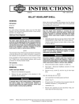
-J04106
REV. 2006-09-07
MINI-TACH WITH SHIFT LIGHT
GENERAL
Kit Numbers
69827-06 matches Nostalgic Face gauges.
69828-06 matches Spun Aluminum Face gauges.
69829-06 matches black face gauges.
Models
When installing any electrical accessory, be certain not
to exceed the maximum amperage rating of the fuse or
circuit breaker protecting the affected circuit being modified. Exceeding the maximum amperage can lead to electrical failures, which could result in death or serious injury.
(00310a)
For model fitment information, please see the P&A Retail Catalog or the Parts and Accessories section of www.harleydavidson.com (English only).
The mini-tach with shift light requires up to 315 milliamps
additional current from the electrical system.
Additional Parts Required
See Figure 7 and Table 1.
A gauge housing kit, and a mini-tach bracket kit that fits the
specific year and model motorcycle are required for proper
installation of this kit.
INSTALLATION
Kit Contents
Preparation
For EFI models:
The rider's safety depends upon the correct installation
of this kit. Use the appropriate service manual procedures.
If the procedure is not within your capabilities or you do
not have the correct tools, have a Harley-Davidson dealer
perform the installation. Improper installation of this kit
could result in death or serious injury. (00333a)
NOTES
This instruction sheet references Service Manual information.
A Service Manual for your model motorcycle is required for
this installation, and is available from a Harley-Davidson Dealer.
Special tools, and additional parts or supplies will also be
needed. See a Harley-Davidson Dealer for further information.
Electrical Overload
To prevent spray of fuel, purge system of high-pressure
fuel before supply line is disconnected. Gasoline is
extremely flammable and highly explosive, which could
result in death or serious injury. (00275a)
Follow the instructions found in the Service Manual to purge
the fuel supply of high pressure gasoline and remove the fuel
supply line.
For ALL models, WITH Maxi-Fuse:
To prevent accidental vehicle start-up, which could cause
death or serious injury, remove maxi-fuse before proceeding. (00251a)
1.
It is possible to overload your motorcycle's charging
system by adding too many electrical accessories. If your
combined electrical accessories operating at any one time
consume more electrical current than your vehicle's
charging system can produce, the electrical consumption
can discharge the battery and cause vehicle electrical
system damage. See a Harley-Davidson dealer for advice
about the amount of current consumed by additional
electrical accessories, or for necessary wiring changes.
(00211b)
-J04106
Refer to the Service Manual and follow the instructions
given to remove the Maxi-Fuse.
For ALL models, WITHOUT Maxi-Fuse:
To prevent accidental vehicle start-up, which could cause
death or serious injury, disconnect negative (-) battery
cable before proceeding. (00048a)
1.
Refer to the Service Manual and follow the instructions
given to remove the seat and disconnect the negative
(black) battery cable from the negative (-) battery terminal.
Retain all seat mounting hardware.
1 of 9
1.
Gasoline can drain from the carburetor fuel line when
disconnected from fuel valve fitting. Gasoline is extremely
flammable and highly explosive, which could result in
death or serious injury. Wipe up spilled fuel immediately
and dispose of rags in a suitable manner. (00256a)
2.
Obtain the mini-tach wire harness (2) from the kit, and
route as follows:
a.
Route the three unterminated leads (B) of the minitach wire harness through the front forks and upper
fork bracket (triple clamp) toward the mini-tach
bracket.
b.
Route the terminated end (C) of the harness back
along the frame backbone toward the seat. Follow
existing wiring where practical.
For carbureted models: Turn the fuel supply valve to
OFF. Remove the fuel line from the valve.
Connect the Black Lead to the Vehicle Ground
When servicing the fuel system, do not smoke or allow
open flame or sparks in the vicinity. Gasoline is extremely
flammable and highly explosive, which could result in
death or serious injury. (00330a)
3.
For ALL models: Follow the instructions in the Service
Manual to remove the instrument console from the fuel
tank.
4.
See FUEL TANK: REMOVAL in the appropriate section
(Carbureted or EFI Engine) of the Service Manual for
instructions to remove the tank.
5.
For all models EXCEPT FLHR or 1986 and later FL
Softail models with Chrome Headlight Nacelle Kit (Part
Number 67907-96): Follow the instructions in the Service
Manual to remove the headlamp housing.
For FLHR models, or Softail models WITH the Nacelle
Kit: Follow the instructions in the Service Manual and the
mini-tach bracket kit (purchased separately) to remove
the handlebar shroud.
Mini-Tach Bracket Installation
6.
Butt splicing is a necessary step in the installation of the minitach to the motorcycle. Refer to SEALED BUTT SPLICE
CONNECTORS in the Service Manual for proper butt splicing
procedures.
Be sure to follow manufacturer's instructions when using
the UltraTorch UT-100 or any other radiant heating device.
Failure to follow manufacturer's instructions can cause a
fire, which could result in death or serious injury. (00335a)
•
Avoid directing heat toward any fuel system component.
Extreme heat can cause fuel ignition/explosion resulting
in death or serious injury.
•
Avoid directing heat toward any electrical system component other than the connectors on which heat shrink work
is being performed.
•
Always keep hands away from tool tip area and heat shrink
attachment.
2.
For all models EXCEPT 1996 through 2003 XL: Locate
the main harness chassis ground connection on the frame.
See the Service Manual for your model and year vehicle
for specific location.
For all models except FLHR: Install the mini-tach bracket
components per the instructions in that kit.
For FLHR models: Follow the instructions in the Service
Manual and the mini-tach bracket kit to install the handlebar shroud and bracket components.
7.
See Figure 7. Select the rubber isolation gasket (1) from
this kit.
a.
Remove the ground screw or nut from the chassis
ground.
b.
Select the appropriate ring terminal (3 or 4) to fit the
ground screw or stud.
c.
Cut the Black wire on the mini-tach wire harness to
easily reach the ground location, and crimp the ring
terminal to the end of the wire according to the
PACKARD crimping tool instructions in the Service
Manual.
d.
Install the ring terminal to the ground connection, and
secure per the torque specification in the Service
Manual.
NOTES
Lubricating the gasket with soap and water will make installation
of the gasket easier.
The attached grommet will be oriented toward the bottom of
the gasket.
8.
Fit the perimeter groove in the rubber isolation gasket to
the inside edge of the bracket and the grommet tab (A) of
the isolation gasket to the square cutout in the bracket.
For 1996 through 2003 XL models: See the SEALED
BUTT CONNECTOR and WIRING DIAGRAM sections of
the Service Manual. Use a butt-splice (6) from the kit to
splice the Black lead from the mini-tach harness to one of
the Black (BK) wire leads coming from the instrument
cluster connector [20].
HARNESS ROUTING AND CONNECTION
NOTES
Kit 69829-06 (black face gauge) contains ring terminals and
wire leads (see Figure 7 and Table 1) that allow installation on
certain models that were manufactured only with black face
gauges.
Kits 69827-06 (Nostalgic face) and 69828-06 (Spun Aluminum
face) do not contain these additional items. Installation of a
Nostalgic- or Spun Aluminum-face kit on these vehicles may
require separate purchase of one or more of these items. See
a Harley-Davidson Dealer for further information.
-J04106
3.
Determine if there is sufficient slack in the lead so that
handlebar movement will not be restricted.
Connect the Pink Lead to the Signal Source
4.
Use the Service Manual wiring diagrams to locate the
tachometer signal source for your model and year vehicle.
2 of 9
For 1984-1999 Softail and 1996-1998 FXDWG models:
The tachometer signal source is the coil primary terminal
with the Pink (PK) or Blue (BE) wire lead attached.
a.
Cut off and discard the terminal on the Pink (PK) minitach wire harness signal lead.
b.
Select the appropriate ring terminal from the kit to fit
the coil stud diameter.
c.
Crimp the ring terminal to the end of the wire
according to the PACKARD crimping tool instructions
in the Service Manual.
d.
Remove the nut from the coil primary terminal with
the Pink (PK) or Blue (BE) wire attached. Place the
ring terminal from the Pink (PK) mini-tach lead to the
coil terminal, and tighten the nut to 4-7 in-lbs (0.4-0.9
Nm).
terminated with a single connector and cable-strapped to
the outside of the conduit.
Cut off and discard the terminal on the Pink (PK) minitach wire harness signal lead.
b.
Obtain the signal adapter wire lead (12) and a buttsplice connector (6) from the kit. See Figure 1. Cut
the Multilock socket terminal from the signal adapter
wire lead, close to that terminal. Splice the signal
adapter wire lead to the mini-tach wire harness signal
lead according to the SEALED BUTT SPLICE CONNECTOR instructions in the Service Manual.
c.
Obtain the signal adapter wire lead (12) and a buttsplice connector (6) from the kit. See Figure 3. Cut
the Deutsch socket terminal from the signal adapter
wire lead, close to that terminal. Splice the signal
adapter wire lead to the mini-tach wire harness signal
lead according to the SEALED BUTT SPLICE CONNECTOR instructions in the Service Manual.
c.
Free the Pink (PK) tachometer signal source wire
from the conduit on the vehicle, and connect the
signal adapter wire lead to the tachometer signal
source wire.
a.
Cut off and discard the terminal on the Pink (PK) minitach wire harness signal lead.
b.
Obtain the signal adapter wire lead (12) and a buttsplice connector (6) from the kit.
See Figure 1 and Figure 3. Cut the un-needed socket
terminal from the signal adapter wire lead, close to
that terminal. Splice the signal adapter wire lead to
the mini-tach wire harness signal lead according to
the SEALED BUTT SPLICE CONNECTOR instructions in the Service Manual.
Free the Pink (PK) tachometer signal source wire
inside the fuel tank console, and connect the signal
adapter wire lead to the tachometer signal source
wire.
a.
Cut off and discard the terminal on the Pink (PK) minitach wire harness signal lead.
b.
Remove the Pink (PK) lead from the ignition or ECM
harness connector cavity #3 according to the
DEUTSCH ELECTRICAL CONNECTOR instructions
in the Service Manual. Cut the lead about one inch
(25.4 mm) from the terminal.
d.
b.
Note: Most 1996-1998 models will have an AMP
Multilock connector in this position, while most 19992003 models will have a Deutsch connector. Verify
connector type before proceeding.
For 1994-1998 FLHR models: The tachometer signal
source is the ignition or ECM harness connector [8] under
the right side cover.
c.
Cut off and discard the terminal on the Pink (PK) minitach wire harness signal lead.
For 1996-2003 XL Custom models: See Figure 4. The
tachometer signal source is the #7 cavity of the instrument
lights connector [20]. The connector is located under the
fuel tank or in the handlebar riser cover on XL Custom
models.
For 1999-2003 FXDWG and 2000-2003 Softail models:
The tachometer signal source is the Pink (PK) wire either
tucked inside or terminated and cable-strapped to the
conduit at the speedometer connector [39B] mounted
inside the fuel tank console.
a.
a.
Obtain a butt-splice connector (6) from the kit. See
Figure 2, the 2 into 1 splice configuration. Splice the
mini-tach wire harness signal lead and two segments
of the Pink (PK) lead from cavity #3 according to the
SEALED BUTT SPLICE CONNECTOR instructions
in the Service Manual.
c.
Follow the AMP MULTILOCK ELECTRICAL CONNECTOR or DEUTSCH ELECTRICAL CONNECTOR
instructions in the Service Manual. Insert the signal
adapter wire lead terminal into cavity #7 of instrument
lights socket housing [20B].
For all other models: The tachometer signal source is
the #3 cavity in the connector [39B] on the back of the
speedometer. See Figure 5.
Follow the PACKARD ELECTRICAL CONNECTOR:
MICRO 64 instructions in the Service Manual. Insert the
socket terminal on the Pink (PK) mini-tach wire harness
signal lead into cavity #3 of connector [39B].
5.
Determine if there is sufficient slack in the lead so that
handlebar movement will not be restricted.
Re-insert the terminal and Pink (PK) lead into cavity
#3 according to the DEUTSCH ELECTRICAL CONNECTOR instructions in the Service Manual.
For 1999-2003 FLHR models: The tachometer signal
source is the Pink (PK) wire near the speedometer connector [39B], either tucked underneath the conduit, or
-J04106
3 of 9
is02802
is02051
2
1
1. Deutsch socket terminal
2. Multilock socket terminal (discard)
1
Figure 1. Cut Multilock Terminal From Adapter Lead
is02055
1
1. Instrument connector #7 cavity
Figure 4. Instrument Lights Connector [20] (2003 XL
Custom shown)
2
is02604
3
1. 1 into 1 splice
2. 2 into 1 splice
3. 3 into 1 splice
Figure 2. Splice Configurations
is02801
2
1
1. Deutsch socket terminal (discard)
2. Multilock socket terminal
Figure 3. Cut Deutsch Terminal From Adapter Lead
-J04106
Figure 5. Speedometer Connector [39] (2004 FXST shown)
Connect the Orange/ White Lead to the Power Source
6.
Use the Service Manual wiring diagrams to locate the
tachometer power source for your model and year vehicle.
4 of 9
For 1984-1995 Softail models: The tachometer power
source is the 15 Amp accessory circuit breaker with two
Orange/ White leads inside the fuel tank console.
a.
Cut off and discard the terminal on the Orange/ White
(O/W) mini-tach wire harness power lead.
b.
Select the appropriate ring terminal from the kit to fit
the circuit breaker stud diameter.
c.
d.
Crimp the ring terminal to the end of the wire
according to the PACKARD crimping tool instructions
in the Service Manual.
a.
Cut off and discard the terminal on the Orange/ White
(O/W) mini-tach wire harness power lead.
b.
Remove the Orange/ White (O/W) lead from the tail
lamp pin housing [7A] cavity #2 according to the AMP
MULTILOCK ELECTRICAL CONNECTOR instructions in the Service Manual. Cut the lead about one
inch (25.4 mm) from the terminal.
d.
a.
Remove the fuse block cover. Remove the two hex
head screws fastening the fuse block bracket, and
pull the bracket and fuse block assembly away from
the motorcycle frame.
b.
Depress the tab retaining the left-hand fuse block,
and slide the block out of the mounting slots.
c.
Locate the fuse cavity indicated as "P&A IGN" on the
fuse block cover. There should be a wire feeding one
side of this circuit, but no mating wire or fuse will be
present. Insert the terminal on the Orange/ White wire
of the mini-tach wire harness until it stops. Refer to a
nearby factory-installed terminal for comparison to
ensure proper orientation and depth.
d.
See Figure 7. Install the 2 Amp fuse (8) from the kit
into the P&A IGN fuse cavity to complete the circuit.
e.
Slide the fuse block into the mounting slots in the fuse
block bracket until it clicks firmly into place. Place the
bracket and fuse block assembly into position, and
fasten with the two hex head screws removed earlier.
Tighten securely. Re-install the fuse block cover.
Remove the nut from the circuit breaker terminal with
two Orange/ White (O/W) wires attached. Place the
ring terminal from the Orange/ White (O/W) mini-tach
lead to the circuit breaker terminal, and tighten the
nut securely.
For 1996-2003 Softail and FXDWG models: The
tachometer power source is the #2 cavity in the tail lamp
connector [7] under the seat.
c.
See the Wiring Diagram for your model and the FUSES
section of the Service Manual.
Obtain a butt-splice connector (6) from the kit. See
Figure 2, the 2 into 1 splice configuration. Splice the
mini-tach wire harness power lead and two segments
of the Orange/ White (O/W) lead from cavity #2
according to the SEALED BUTT SPLICE CONNECTOR instructions in the Service Manual.
For 2004 and later FXDWG models: The tachometer
power source is an open fuse position on the electrical
caddy. See the Wiring Diagram for your model and the
ELECTRICAL CADDY section of the Service Manual.
a.
Remove the electrical caddy from the vehicle per the
Service Manual instructions.
b.
Locate the fuse cavity indicated as "OPEN" on the
electrical caddy. There should be a wire feeding one
side of this circuit, but no mating wire or fuse will be
present. Insert the terminal on the Orange/ White wire
of the mini-tach wire harness until it stops. Refer to a
nearby factory-installed terminal for comparison to
ensure proper orientation and depth.
c.
See Figure 7. Install the 2 Amp fuse (8) from the kit
into the OPEN fuse cavity to complete the circuit.
d.
Re-install the electrical caddy and cover onto the
vehicle per the instructions in the ELECTRICAL
CADDY section of the Service Manual.
Re-insert the terminal and Orange/ White (O/W) lead
into cavity #2 according to the AMP MULTILOCK
ELECTRICAL CONNECTOR instructions in the Service Manual.
For 2004 and later Softail models: The tachometer
power source is an open fuse position on the fuse panel.
For 1994-2003 FLHR models: The tachometer power
source is an orange/ white (O/W) main harness power
lead inside the right side cover, near the top.
a.
Cut off and discard the terminal on the Orange/ White
(O/W) mini-tach wire harness power lead.
b.
Obtain a butt-splice connector (6) from the kit. Carefully slice open an area of the main harness wrap,
and cut an Orange/ White (O/W) main harness power
lead at an accessible point. Splice the mini-tach wire
harness power lead to the main harness power lead
according to the SEALED BUTT SPLICE CONNECTOR instructions in the Service Manual.
For 2004 through 2006 FLHR models: The tachometer
power source is an open fuse position on the fuse panel.
-J04106
5 of 9
See the Wiring Diagram for your model and the SYSTEM
FUSES section of the Service Manual.
a.
Remove the left-hand side cover, fuse block and dust
cover per the instructions in the Service Manual.
b.
Locate the fuse cavity indicated as "P&A IGN" "2A
MAX". There should be a wire feeding one side of
this circuit, but no mating wire or fuse will be present.
Remove the three existing fuses in this row, noting
their location.
c.
Gently remove the orange plastic secondary lock from
the fuse block.
d.
See Figure 7. Obtain the Orange/ White power
adapter wire (7) from the kit. Insert the terminal on
the adapter wire into the "P&A IGN" "2A MAX" cavity
until it stops. Refer to a nearby factory-installed terminal for comparison to ensure proper orientation and
depth.
For 1996-2003 XL Custom models: See Figure 6. The
tachometer power source is an Orange/ White (O/W) main
harness power lead inside the side cover or under the
seat.
b.
Locate the fuse cavity indicated as "P&A IGN" "2A
MAX". There should be a wire feeding one side of
this circuit, but no mating wire or fuse will be present.
Insert the terminal on the Orange/ White wire of the
mini-tach wire harness until it stops. Refer to a nearby
factory-installed terminal for comparison to ensure
proper orientation and depth.
Re-install the three fuses removed in Step b (above)
into the proper cavities.
c.
See Figure 7. Install the 2 Amp fuse (8) from the kit
into the P&A IGN fuse cavity to complete the circuit.
Install the dust cover onto the fuse block, and install
the fuse block per the instructions in the Service
Manual.
d.
Re-fasten the "H"-bracket to the vehicle frame per
the instructions in the Service Manual. Re-install the
left-hand side cover.
Cut the excess length from the Orange/ White wire
of the mini-tach wire harness to within easy reach
of the Orange/ White adapter wire installed in Step
6d.
g.
Install the 2 Amp fuse (8) from the kit into the P&A
IGN fuse cavity to complete the circuit.
For 2007 and later FLHR models: The tachometer power
source is an open fuse position on the fuse panel. See
the Wiring Diagram for your model and the SYSTEM
FUSES section of the Service Manual.
a.
Remove the right-hand side cover, fuse block and
dust cover per the instructions in the Service Manual.
b.
Locate the fuse cavity indicated as "P&A IGN" "2A
MAX". There should be a wire feeding one side of
this circuit, but no mating wire or fuse will be present.
Remove the three existing fuses in this row, noting
their location.
c.
Gently remove the orange plastic secondary lock from
the fuse block. Insert the terminal on the Orange/
White wire of the mini-tach wire harness until it stops.
Refer to a nearby factory-installed terminal for comparison to ensure proper orientation and depth.
is02049
1
2
1. Power (O/W) lead in main harness
2. Ground
Re-install the secondary lock.
See Figure 7. Install the 2 Amp fuse (8) from the kit
into the P&A IGN fuse cavity to complete the circuit.
Re-install the three fuses removed in Step b (above)
into the proper cavities.
e.
-J04106
Obtain a butt-splice connector (6) from the kit. Carefully slice open an area of the main harness wrap,
and cut an Orange/ White (O/W) main harness power
lead at an accessible point. Splice the mini-tach wire
harness power lead to the main harness power lead
according to the SEALED BUTT SPLICE CONNECTOR instructions in the Service Manual.
Remove the left-hand side cover from the vehicle.
Loosen the "H"-bracket per the instructions in the
Service Manual, and pull it away from the frame to
gain access to the back side of the fuse block.
Using a butt-splice connector (6) from the kit, splice
the two Orange/ White wires.
d.
b.
a.
f.
h.
Cut off and discard the terminal on the Orange/ White
(O/W) mini-tach wire harness power lead.
For 2007 and later XL Custom models: The tachometer
power source is an open fuse position on the fuse panel.
See the Wiring Diagram for your model and the SYSTEM
FUSES section of the Service Manual.
Re-install the secondary lock.
e.
a.
Install the dust cover onto the fuse block, and install
the fuse block per the instructions in the Service
Manual.
Figure 6. Wire Harness and Ground Location (2003 or
earlier XL)
7.
ALL models: At the front of the vehicle, lubricate the minitach harness conduit with soapy water, and pull the three
unterminated leads and conduit up through the grommet
at the bottom of the isolation gasket.
6 of 9
8.
Obtain the mini-tach (10) from the kit. Orient the face of
the gauge so it reads upright, and slide the mini-tach into
the bracket and isolation gasket from the front side.
9.
Obtain the three small ring terminals (5) from the kit, and
crimp the terminals to the mini-tach harness wire ends
according to the Packard crimping tool instructions in the
Service Manual.
10. Install the ring terminals to the back of the mini-tach,
matching the wire colors to the proper terminal posts as
follows:
a.
Orange/ White (power) to post marked "+".
b.
Black (ground) to post marked "G".
c.
Pink (signal) to post marked "S".
NOTE
Over-tightening the nuts may damage the mini-tach.
Apply a light coat of petroleum jelly or corrosion retardant
material to the battery terminal.
2.
Locate the black rubber plunger on the back of the gauge.
The plunger is a programming tool that also acts as a hole
plug when not in use.
3.
Gently pull the plunger from the back of the gauge. Rotate
the plunger, and insert the long end back into the hole to
act as a tool to reach the programming button on the circuit
board inside the mini-tach.
4.
Turn the Ignition/ Light Key Switch to ON to power the
mini-tach, but do not start the motorcycle.
5.
Using the plunger tool, press the button on the circuit board
and hold until the shift light on the gauge face flashes one
time, and the tachometer needle moves to the current set
point.
6.
Use individual clicks on the circuit board button to advance
the needle upward by fine adjustments to the desired shift
point.
11. Use the nut and lock washer on each post to secure the
ring terminal to that post. Tighten the nuts to 4-7 in-lbs
(0.4 to 0.9 Nm).
a.
If the desired shift point is exceeded by use of the
individual clicks on the circuit board button, press
and hold the button to cause the needle to move to
full scale, then swing to "0" and continue to advance
until the button is released.
b.
Release the button as the desired shift point is
approached, and again use individual clicks to reach
the desired shift point.
Verify that the ring terminals or wire leads are not
grounding against each other.
12. Use cable straps (9) from the kit to secure the mini-tach
wire harness to the vehicle harnesses.
SHIFT LIGHT PROGRAMMING
Prior to installing the gauge housing to the back of the minitach, the shift light setting must be programmed into the gauge.
7.
Do not over-tighten bolts on battery terminals. Use recommended torque values. Over-tightening battery terminal
bolts could result in damage to battery terminals. (00216a)
When the desired shift light trigger point has been
selected, release the button and allow the programming
sequence to timeout (approximately three seconds). The
shift light will flash rapidly three times, indicating that the
desired shift point has been successfully entered.
8.
Turn the Ignition/ Light Key Switch to OFF.
1.
9.
Models WITH Maxi-Fuse: Refer to the Service Manual
and follow the instructions given to re-install the Maxi-Fuse.
Follow the instructions in the gauge housing kit and press
the gauge housing into the isolation gasket, capturing the
grommet in the housing cutout. Fasten the housing to the
mini-tach with the flat head screw from that kit.
Models WITHOUT maxi-fuse: Re-connect the negative
(-) battery cable per the instructions in the Service Manual.
10. Check the seal of the isolation gasket around the entire
perimeter of the housing.
Verify that the Ignition/ Light Key Switch is in the OFF
position.
-J04106
7 of 9
FINAL ASSEMBLY
NOTES
During re-assembly, check the wire harness along its entire
length for clearance from moving parts, heat sources, sharp
edges and pinch points.
Flex the front suspension, and turn the front forks to the full
left and right stops to check for smooth and free operation and
pulling or binding of the harness.
1.
For all models except FLHR: Follow the instructions in
the Service Manual to re-install the headlamp housing.
For FLHR models: Follow the instructions in the Service
Manual to re-install the handlebar shroud.
Do not run the engine at extremely high RPM with clutch
disengaged or transmission in neutral. Running an engine
at high RPM can result in engine damage. (00177a)
NOTES
Refer to the OPERATING RECOMMENDATIONS in the
Owner's manual for the maximum recommended engine speed
for your model.
Allow the engine to reach normal operating temperature before
checking that the desired shift light trigger point has been
successfully programmed into the mini-tach.
4.
When servicing the fuel system, do not smoke or allow
open flame or sparks in the vicinity. Gasoline is extremely
flammable and highly explosive, which could result in
death or serious injury. (00330a)
Turn the Ignition/ Light Key Switch to ON, and start the
motorcycle.
a.
With engine idling, the mini-tach should indicate idle
RPM (950 to 1150 RPM).
b.
The mini-tach should respond to changes in the
throttle settings.
2.
Install the fuel tank. Refer to FUEL TANK, INSTALLATION
(Carbureted or EFI Engine) in the Service Manual.
5.
Follow the instructions in the Service Manual to align the
headlamp.
3.
Refer to the Service Manual, and follow the instructions
given to re-install the seat.
6.
Ride the motorcycle until the engine has warmed up. When
the engine has reached normal operating temperature,
increase engine RPM to the selected set point. The shift
light should illuminate.
After installing seat, pull upward on seat to be sure it is
locked in position. While riding, a loose seat can shift
causing loss of control, which could result in death or
serious injury. (00070b)
-J04106
There is a built-in timer to turn off the shift light if the gauge
stays at the set point RPM for an extended time.
7.
If the shift light does not illuminate at the desired point,
refer to the SHIFT LIGHT PROGRAMMING section of
these instructions to re-enter the desired shift point.
8 of 9
SERVICE PARTS
is02605
13
1
9
12
10
4
3
11
7
5
2
8
6
C
A
B
Figure 7. Service Parts, Mini-Tach Gauge Kit
Table 1. Service Parts Table
Kit
Common items
for ALL kits
Item
Description (Quantity)
Part Number
1
Gasket, mini-tach isolation
67952-96
2
Wire harness, mini-tach
67245-04A
3
Ring terminal, #18-22 AWG (1/4 in. stud)
9858
4
Ring terminal, #18-22 AWG (5/16 in. stud)
9859
5
Ring terminal, #18-22 AWG (#6 stud) (3)
9856
6
Butt-splice connector, #18-20 AWG (red)
70585-93
7
Wire lead, power adapter, 4 in. (102 mm) long, (Orange/ White)
67969-04
8
Fuse, blade type, 2A
54305-98
9
Wire tie (6)
10006
Kit 69827-06
(Nostalgic face)
additional contents
10
Gauge, mini-tach (with shift light)
Not sold separately
Kit 69828-06
(Spun Aluminum
face)
additional contents
10
Gauge, mini-tach (with shift light)
Not sold separately
Kit 69829-06
(Black face)
additional contents
10
Gauge, mini-tach (with shift light)
Not sold separately
11
Ring terminal, #18-22 AWG (#10 stud) (3)
9857
12
Wire lead, signal adapter, 24 in. (0.6 m) long (Pink)
70231-04
13
Wire lead, signal extension, 32 in. (0.8 m) long (Pink)
70230-04
Items mentioned in text, but not included in kits:
-J04106
A
Grommet tab on isolation gasket
B
Unterminated end of mini-tach wire harness
C
Terminated end of mini-tach wire harness
9 of 9