1
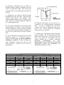
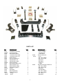
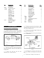
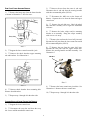
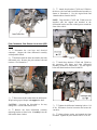
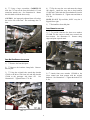
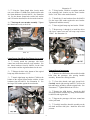
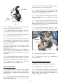
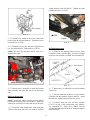
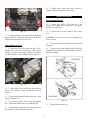
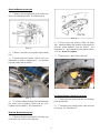
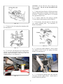
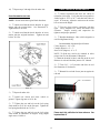
88569 Rev C
Suspension System RS6569B
Chevrolet Colorado / GMC Canyon
88569 Rev C
READ ALL INSTRUCTIONS THOROUGHLY FROM START TO FINISH BEFORE BEGINNING INSTALLATION
IMPORTANT NOTES!
USS washer against the slotted hole and the SAE
washer against the round hole.
WARNING:
This suspension system will
enhance the off-road performance of your vehicle.
It will handle differently, both on and off-road,
from a factory equipped passenger car or truck.
Extreme care must be used to prevent loss of
control or vehicle rollover during abrupt
maneuvers. Failure to drive this vehicle safely
may result in serious injury or death to the driver
and passengers. ALWAYS WEAR your seat
belts, REDUCE your speed, and AVOID sharp
turns and other abrupt maneuvers.
G. Apply a drop of thread locking compound to
all bolts during installation. CAUTION: Thread
locking compound may irritate sensitive skin.
Read warning label on container before use.
H. Unless otherwise specified, tighten all nuts
and bolts to the standard torque specifications
shown in the table on page 2. USE A TORQUE
WRENCH for accurate measurements.
A. Before installing this system, have the
vehicle’s alignment and frame checked by a
certified technician. The alignment must be
within factory specifications and the frame of the
vehicle must be sound (no cracks, damage or
corrosion).
I. Some of the service procedures require the use
of special tools designed for specific procedures.
The following tools and supplies are
recommended for proper installation of this
system:
B. Do not install a body lift kit with this
suspension system or interchange Rancho
components
with
parts
from
another
manufacturer. Use the appropriate Rancho shock
absorbers.
Colorado/Canyon Service Manual
Universal Steering Linkage Puller J24319
Ball Joint Separator J43631
Torque Angle Meter J36660-A
Die Grinder
Drill motor
Assorted Drills: 1/8" through 1/2"
Torque Wrench (250 FT-LB capacity)
1/2” Drive Ratchet and Sockets
Assorted Combination Wrenches
Heavy Duty Jack Stands
Wheel Chocks (wooden blocks)
Hydraulic Floor Jack
Center punch
File
Hammer
Wire Brush (to clean bracket mounting surfaces)
Black Enamel Paint
Brake Fluid
Tape Measure
Safety Glasses (wear safety glasses at all times)
C. Do not powdercoat or plate any of the
components in this system. To change the
appearance of components, automotive paint can
be applied over the original coating.
D. Each hardware kit in this system contains
fasteners of high strength and specific size. Do
not mix hardware kits or substitute a fastener of
lesser strength. See bolt identification table on
page 2.
E. Compare the contents of this system with the
parts list in these instructions. If any parts are
missing, contact the Rancho Technical
Department at 1-734-384-7804.
J. It is extremely important to replace torsion
bars, CV flanges, and front drive shaft/pinion
relationships as original.
Be sure to mark
left/right, front/rear, and indexing of mating parts
before disassembly. A paint marker or light
colored nail polish is handy for this.
F. Install all nuts and bolts with a flat washer.
When both SAE (small OD) and USS (large OD)
washers are used in a fastener assembly, place the
2
K. Suspension components that use rubber or
urethane bushings should be tightened with the
vehicle at normal ride height. This will prevent
premature failure of the bushing and maintain ride
comfort.
L. Welding on a car creates an electrical charge
throughout the body and frame. Disconnect the
vehicle’s battery prior to any welding. Place
welding ground clamps as near as possible to the
weld. Never use a vehicle suspension component
as a welding ground point.
O. Important information for the end user is
contained in the consumer/installer information
pack. If you are installing this system for
someone else, place the information pack on the
driver’s seat. Please include the installation
instructions when you finish.
M. The required installation time for this system
is approximately 4 to 5 hours. Check off the box
at the beginning of each step when you finish
it. Then when you stop during the installation, it
will be easier to find where you need to continue
from.
P. Thank you for purchasing the best suspension
system available. For the best-installed system,
follow these instructions. If you do not have the
tools or are unsure of your abilities, have this
system installed by a certified technician.
RANCHO
SUSPENSION
IS
NOT
RESPONSIBLE FOR DAMAGE OR FAILURE
RESULTING FROM AN IMPROPER OR
MODIFIED INSTALLATION…
N. The recommended tire and wheel size for this
suspension system is a 285/70 R17 with 4.5
inches of wheel backspacing. Minor wheelhouse
trimming is required. Before installing any
other combination, consult your local tire and
wheel specialist. Actual tire size varies by
manufacturer.
Bolt Size
5/16
3/8
7/16
1/2
9/16
5/8
3/4
STANDARD BOLT TORQUE SPECIFICATIONS
INCH SYSTEM
METRIC SYSTEM
Grade 5
Grade 8
Bolt Size
Class 9.8
Class 10.9
15 FT-LB
30 FT-LB
45 FT-LB
65 FT-LB
95 FT-LB
135 FT-LB
185 FT-LB
20 FT-LB
35 FT-LB
60 FT-LB
90 FT-LB
130 FT-LB
175 FT-LB
280 FT-LB
M6
M8
M10
M12
M14
M16
M18
3
5 FT-LB
18 FT-LB
32 FT-LB
55 FT-LB
85 FT-LB
130 FT-LB
170 FT-LB
9 FT-LB
23 FT-LB
45 FT-LB
75 FT-LB
120 FT-LB
165 FT-LB
240 FT-LB
Class 12.9
12 FT-LB
27 FT-LB
50 FT-LB
90 FT-LB
145 FT-LB
210 FT-LB
290 FT-LB
PARTS LIST
P/N
170107
176346B
176348
176352
176353
176357
176399
176403
176404
176405B
176406
176407
176408
176409
176410B
176413
176414
860521
520041
420042
DESCRIPTION
Box 1 of 2
Front Brake Hose Assembly
Front Cross Member
Differential Drop Bracket
Torsion Bar Relocator, Right
Torsion Bar Relocator, Left
Aft Brace Bracket
Rear Leaf Spring Bracket
Sway Bar Bracket, Left
Sway Bar Bracket, Right
Rear Cross Member
Differential Drop Bracket, Rear
Bump Stop Bracket, Left
Bump Stop Bracket, Right
Rear Bump Stop Bracket
Aft Brace
Rear Shackle
Differential Skid Plate
Aft Brace Bushing Kit
Bushing
Sleeve
P/N
860522
QTY.
2
1
2
1
1
2
2
1
1
1
2
1
1
2
2
2
1
1
8
4
860528
420061
860554
4
DESCRIPTION
Aft Brace Hardware Kit
1/2-13 x 4.0 HHCS
1/2-13 Stover Nut
1/2 SAE Washer
Aft Brace Hardware Kit
Sleeve
M12-1.75 x 80 HHCS
M12-1.75 Stover Nut
M12 Washer
USS Washer
Thread Lock
Tie Wrap
Sway Bar & Bump Stop Hardware Kit
M12-1.75 x 30 HHCS
M12-1.75 Stover Nut
M12 Washer
7/16 USS Washer
M10-1.25 x 30 HHCS
M10-1.25 x 50 HHCS
M10-1.25 Nut
M10 Washer
QTY.
1
4
4
8
1
2
2
2
2
2
2
5
1
2
2
2
2
4
2
6
12
P/N
860555
170014
420062
860556
DESCRIPTION
Loop Strap
9/16 USS Washer
Rear Hardware Kit
Rear Brake Line Bracket
Sleeve
M8-1.25 x 20 HHCS
M8 Washer
5/16-18 x 1.25 HHCS
5/16-18 Nut
M10-1.50 x 75 HHCS
M10 Washer
M12-1.75 x 40 HHCS
M12-1.75 Stover Nut
M14-2.0 x 120 HHCS
M14-2.0 Nut
M14 Washer
1/2 USS Washer
Cross Member Hardware Kit
M16-2.00 x 120 HHCS
M16-2.00 Nut
M16 Washer
QTY.
2
2
1
1
2
1
3
1
1
4
4
2
2
2
2
4
4
1
2
2
4
P/N
94180
780281
88569
94119
94177
176411
176412
FRONT SUSPENSION
DESCRIPTION
M10-1.25 x 30 HHCS
7/16 USS Washer
M10-1.25 x 35 HHCS
M10 Lock Washer
M10 Washer
M14-2.00 x 40 HHCS
M14 Washer
M14-2.00 Stover Nut
M10-1.50 x 60 HHCS
M10-1.50 Nyloc Nut
M10-1.25 Top Lock Nut
1/2 Rubber Washer
Information Pack
Rancho Decal
Instruction
Consumer/Warranty Information
Warning Sticker
Box 2 of 2
Knuckle, Left
Knuckle, Right
QTY.
2
2
3
4
12
4
8
4
4
4
1
5
1
1
1
1
1
1
1
4)
Mark the torsion bars left and right. Make
alignment marks on the torsion bars, the lower control
arms, and the adjustment arms.
VEHICLE PREPARATION & TORSION BAR REMOVAL
1)
Park the vehicle on a level surface. Set the
parking brake and chock rear wheels. Measure and
record the distance from the center of each wheel to
the top of the fender opening. See illustration 1.
5)
Measure and record the length of adjuster bolt
threads above the adjuster nut.
6)
Remove the adjuster bolt, spacer and adjuster
nut. See illustration 2.
Illus. 1
2)
Raise the front of the vehicle and support the
frame with jackstands. Remove the front wheels and
set them aside.
Illus. 2
3)
Remove the push pins from the inner
wheelhouse liners. Remove the liners.
7)
Disengage the torsion bar from the lower
control arm. Remove the adjustment arm and torsion
bar.
8)
5
Repeat steps 5 through 7 for the other side.
BUMP STOP & SHOCK ABSORBER REMOVAL
3)
Remove the nut from the outer tie rod stud.
Disconnect the tie rod end from the steering knuckle
with the recommended puller (J24319).
1)
Remove the bump stop from the frame bracket
as shown in illustration 3. Save for reuse.
4)
Disconnect the ABS wire at the frame rail
harness. Separate the wire from the frame and upper
control arm.
5)
Remove the axle hub nut. Label the wheel
hub and rotor assembly left or right for installation
reference.
6)
Remove the brake caliper and its mounting
bracket as an assembly. Hang the caliper assembly
with wire or a tie wrap.
7)
Remove the nut from the lower ball joint stud.
Separate the ball joint from the lower control arm with
the recommended puller (J43631).
Illus. 3
2)
8)
Remove the nut from the upper ball joint.
Separate the ball joint from the upper control arm.
Remove the steering knuckle and hub assembly. See
illustration 5.
Support the lower control arm with a jack.
3)
Remove the shock absorber upper mounting
nut and insulator. See illustration 4.
ABS Wire
Steering
Knuckle
Illus. 5
Illus. 4
9)
Remove the lower control arm pivot bolts. See
illustration 6. Remove the lower control arm.
4)
Remove shock absorber lower mounting bolt.
Remove shock absorber.
5)
10)
Repeat steps 1 through 4 for the other side.
STEERING KNUCKLE & LOWER CONTROL ARM REMOVAL
1)
Support the lower control arm.
2)
Disconnect the sway bar end from the sway
bar. Leave end link attached to control arm.
6
Repeat steps 1 through 9 for the other side.
5)
Attach drop brackets 176348 and 176406 to
the driver side frame and front differential assembly as
shown in illustration 8. Use the original bolts and
14mm hardware from kit 860556.
NOTE: Drop brackets 176352 and 176406 must be
installed with the angled end attached to the
differential bracket and the welded gusset toward the
front of the vehicle.
Illus. 6
FRONT DIFFERENTIAL DROP BRACKET INSTALLATION (4WD
ONLY)
1)
Disconnect the vent hose and electrical
connector. Support the front differential assembly
with adjustable stands.
Illus. 8
2)
Reference mark the front driveshaft to the front
differential yoke. Remove the yoke retainer bolts and
retainers. See illustration 7.
6)
Attach drop brackets 176348 and 176406 to
the passenger side frame and front differential
assembly as shown in illustration 9. Use the original
bolts and 14mm hardware from kit 860556.
Illus. 7
3)
Disconnect the driveshaft from the differential.
Wrap bearing caps with tape and support the shaft.
Illus. 9
CAUTION: Lowering the driveshaft to far may
damage the CV boot at the transfer case.
7)
Tighten the differential mounting bolts to 114
ft. lbs. Reconnect electrical connector and secure the
vent hose.
4)
Remove the front differential assembly
mounting bracket to frame bolts. Carefully lower the
differential about 4 inches.
8)
Align reference marks and reattach the front
diveshaft. Tighten the yoke retainer bolts to 19 ft. lbs.
7
4)
Flip the sway bar over and rotate the clamps
180 degrees. Attach the sway bar to drop brackets
176403 and 176404 with the 10mm hardware from kit
860554. See illustration 11. Tighten nuts and bolts to
37 ft. lbs.
9)
Using a large screwdriver, CAREFULLY
slide the CV boot on the front driveshaft 1/4” back
toward the transfer case. See illustration 10. Rotate
the driveshaft to slide the boot evenly.
CAUTION: An improperly adjusted boot will reduce
the service life of the boot. Do not damage the CV
boot.
NOTE: DO NOT flip end links, ONLY sway bar is
flipped left to right.
5)
Reinstall the front skid plate.
CROSS MEMBER INSTALLATION
1)
To provide clearance for front cross member
176346B, file the corners in both lower control arm
front mounts. See illustration 12. Remove sharp
edges and paint exposed metal.
Illus. 10
SWAY BAR DROP BRACKET INSTALLATION
1)
Remove the front skid plate.
2)
Remove the insulator clamp bolts. Remove
the sway bar.
Illus. 12
3)
Using the original bolts, attach drop bracket
176403 to the driver side frame rail and drop bracket
176404 to the passenger side frame rail.
See
illustration 11. Tighten bolts to 37 ft. lbs.
2)
Attach front cross member 176346B to the
lower control arm front mounts with the original
hardware. See illustration 13. Tighten the bolts to 122
ft. lbs.
Illus. 13
Illus. 11
8
Illustration 15
4)
Using bracket 176408 as a template, mark the
rear mounting hole location on the frame bracket.
Drill a 31/64” hole at the marked location.
3)
Using the 30mm length bolts, loosely attach
rear cross member 176405B to the frame brackets with
the 10mm hardware from kit 860556. See illustration
14. Use the shorter 10mm bolts (with a lock washer
and USS washer installed) for the two inside locations.
5)
Install the 12 mm hardware from kit 860554.
Use the larger USS washer against the new bracket.
Tighten nuts and bolts securely.
4)
Push up the cross member assembly. Tighten
the 10mm bolts evenly to 40 ft. lbs.
6)
Insert original bump stop into bracket 176408.
7)
Repeat steps 1 through 6 to install the driver
side lower control arm and left bump stop bracket
176407. See illustration 16.
Illus. 14
LOWER CONTROL ARM & BUMP STOP BRACKET INSTALLATION
1)
Loosely attach the passenger side lower
control arm to the front and rear cross members. Use
the 16mm hardware from kit 860556 for the front
cross member and the original hardware for the rear.
Illus. 16
STEERING KNUCKLE INSTALLATION
2)
Enlarge the hole in the bottom of the original
bump stop frame bracket to 13/32”.
1)
Remove the ABS bracket bolt and the four hub
bolts from the passenger side steering knuckle
assembly. Remove the steering knuckle.
3)
Attach right bump stop bracket 176408 to the
bottom of the original frame bracket with the 10 mm
hardware from kit 860554. See illustration 15. Use
the larger USS washer against the new bracket.
2)
Clean bolt threads and apply thread lock.
Carefully attach right steering knuckle 176412 to the
hub and bearing assembly with the original bolts. See
illustration 17. Tighten hub bolts to 92 ft. lbs.
3)
Remove the ABS bracket. Attach the ABS
wire to the knuckle with the loop strap (from hardware
kit 860554) and original bolt.
4)
Support the passenger side lower control arm
with a jack stand.
5)
Carefully install the knuckle assembly on the
axle shaft and lower ball joint. Install the lower ball
joint nut.
9
3)
Remove bolt and gaskets from brake caliper.
Remove brake hose. Do not reuse gaskets.
176412
4)
Attach new brake hose 170107 to the caliper
with the supplied washers and original bolt. See
illustration 18. Tighten bolt to 32 ft. lbs.
5)
Insert brake hose through frame bracket.
Install 9/16” USS washer from kit 860554 over fitting
on top of bracket.
ABS
Mounting Boss
6)
Remove plug and attach brake line to brake
hose. While keeping the hose from turning, tighten the
brake line fitting to 14 ft. lbs. Secure hose to bracket
with the new E-type retaining clip.
Do not use impact wrench
Illus. 17
6)
Insert the upper ball joint into the steering
knuckle. Install the upper ball joint nut.
7)
Reconnect ABS electrical connector. Attach
wire to upper control arm. Reinstall wheelhouse liner.
7)
Tighten the lower ball joint nut to 107 ft. lbs.
Tighten the upper ball joint nut and bolt to 55 ft. lbs.
8)
Apply thread lock and install the washer and
axle hub nut. Tighten the nut to 191 ft. lbs.
9)
Rotate tie rod end 180 degrees and attach to
steering knuckle. Tighten nut to 33 ft. lbs on the first
pass. Tighten an additional 95 degrees using torque
angle meter J 36660-A.
10)
Loosen the jam nut on the tie rod end. Rotate
the inner tie rod into the tie rod end three turns.
Tighten the jam nut.
ATTENTION: Tie Rod may need to be trimmed to
allow for proper Toe In adjustment. See Note after
Recommended Alignment Specifications at end of
instructions.
Illus. 18
8)
Repeat steps 1 through 7 for the other side.
11)
Set the spindle to fender height at 24.5 inches.
Tighten the lower control arm rear bolt to 133 ft. lbs.
Tighten the lower control arm front bolt to 122 ft. lbs.
9)
Bleed front
recommendations.
brakes per
manufacturer’s
12)
Repeat steps 1 through 11 to install left
steering knuckle 176411 on the driver side.
SHOCK ABSORBER & END LINK INSTALLATION
CAUTION: Do not use original shock absorbers.
BRAKE HOSE REPLACEMENT
1)
1)
Reattach the brake caliper with the original
mounting bolts. Be sure to clean the bolt threads and
apply thread lock. Tighten the caliper mounting bolts
to 129 ft. lbs.
2)
Install washer and bushing on shock absorber
stud. Insert shock stud through upper mounting hole.
Install bushing, washer and nut. See illustration 19.
Tighten the upper nut to 22 ft. lbs.
2)
Disconnect brake line from brake hose at the
frame bracket. Plug brake line to prevent fluid loss.
Remove the retaining clip.
10
Support the driver side lower control arm.
10mm hardware from kit 860556. Tighten the front
bolt then the rear to 32 ft. lbs.
Illus. 19
3)
Attach lower mount to the lower control arm
bracket with the original hardware. Tighten the lower
nut and bolt to 59 ft. lbs.
Illus. 21
4)
Reattach left sway bar end link to flipped sway
bar. See illustration 20. Tighten nuts to 32 ft. lbs.
AFT BRACE INSTALLATION
NOTE: DO NOT flip end links, ONLY sway bar is
flipped left to right.
1)
Lubricate two bushings and one sleeve (from
kit 860521) with a silicone spray. Press the bushings
and sleeve into aft brace 176410B. See illustration 22.
Sway Bar
DRIVER SIDE (LEFT) Control Arm & End Link
Illus. 20
Illus. 22
5)
Repeat steps 1 through 4 to install the Rancho
shock absorber and right end link on the passenger
side.
2)
Repeat step 1 to install the rest of the bushings
and sleeves.
SKID PLATE INSTALLATION
3)
Loosely attach the aft braces to cross member
176405B with the hardware from kit 860522. Angle
the aft braces slightly outward from front to rear.
NOTE: Install the rubber washers from kit 860556
between the skid plate and cross members. Install two
washers for each of the rear bolts and one for the front.
4)
Loosely attach the two aft brace brackets
(176357) on top of the transmission cross member.
See illustration 23. Insert sleeve 420061 into the
existing hole and attach the brackets with the hardware
from kit 860528.
1)
Using the 35mm length bolts, attach skid plate
176414 to the front and rear cross members with the
11
6)
Install front wheels and lower vehicle to
ground. Tighten the lug nuts to 103 ft. lbs.
REAR SUSPENSION
SHOCK ABSORBER REMOVAL
1)
Chock front wheels. Raise the rear of the
vehicle and support the frame with jack stands.
Remove the rear wheels.
Illus. 23
2)
jack.
Support the rear axle assembly with a floor
5)
Attach aft braces to brackets with the hardware
from kit 860522. Tighten the bracket to cross member
bolts then the aft brace bolts to 45 ft. lbs.
CAUTION: Do not allow the axle to hang by any
hoses or cables.
TORSION BAR INSTALLATION
3)
Disconnect the rear differential vent hose from
the frame.
1)
Fully insert left torsion bar relocator 176353
into the driver side lower control arm. Align the hex
opening as close to the original bushing as possible.
See illustration 24. Transfer index mark to relocator.
4)
Remove the shock absorber upper and lower
mounting bolts and nuts. See illustration 25. Remove
the shock absorber.
Illus. 24
2)
Align mark on left torsion bar with mark on
torsion bar relocator. Insert torsion bar into left
relocator.
3)
Align marks and install torsion bar arm. Refer
back to illustration 2.
Illus. 25
4)
Install the adjuster bolt, spacer and adjuster
nut. Tighten the adjuster bolt to its original height.
5)
5)
Repeat steps 1 through 4 to install right torsion
bar relocator 176352 on the passenger side.
12
Repeat for the other side.
BRAKE LINE BRACKET INSTALLATION
1)
Remove the mounting bolt for the brake hose
at the rear differential bracket. See illustration 26.
Illus. 28
2)
Place bump stop bracket 176409 on bump
stop. Attach the bump stop assembly to the frame rail
with the 10mm hardware from kit 860555. See
illustration 29. Apply thread lock and tighten bolts to
27 ft. lbs. Do not over tighten.
Illus. 26
2)
bolt
Remove the brake hose bracket and mounting
3)
Repeat steps 1 and 2 for the other side.
3)
Attach brake line bracket 170014 to the rear
differential as shown in illustration 27. Use the 8mm
bolt and washer from kit 860555.
Illus. 29
LEAF SPRING BRACKET & SHACKLE INSTALLATION
Illus. 27
1)
Loosen the leaf spring front and rear mounting
bolts on both sides.
4)
Carefully reshape the brake lines and attach the
rear brake hose to bracket 170014 with the 5/16”
hardware from kit 860555. See illustration 27.
2)
Disconnect the parking brake cable from the
leaf spring. See illustration 30
BUMP STOP BRACKET INSTALLATION
1)
Remove the bolts attaching the rear bump stop
to the frame rail. Remove the bump stop.
13
CAUTION: Do not allow the axle to hang by any
hoses or cables. Do not rest the driveshaft on the
cross member.
5)
Attach the front of bracket 176399 to the frame
with the 12mm hardware and larger USS washers from
kit 860555. Tighten the 12mm bolt to 55 ft. lbs then
the 14mm bolt to 85 ft. lbs.
6)
Loosely attach the leaf spring to bracket
176399 with the 14mm hardware from kit 860555.
7)
If necessary, lower the spare tire. Remove the
rear shackle mounting bolts. See illustration 33.
Remove the shackle.
Illus. 30
3)
Remove the leaf spring front mounting bolt.
See illustration 31.
Illus. 33
Illus. 31
8)
Using the original hardware, loosely attach
rear shackle 176413 to the leaf spring and frame
bracket. See illustration 34.
4)
Lower the axle and place leaf spring bracket
176399 over the original frame bracket. Using sleeve
420062, attach the bracket to the frame with the
original hardware. See illustration 32.
Illus. 34
9)
To reattach the parking brake cable, bend the
leaf spring bracket slightly inward. Attach cable to
bracket with the original bolt.
Illus. 32
14
10)
FINAL CHECKS & ADJUSTMENTS
Repeat steps 2 through 9 for the other side.
1)
Jounce suspension and move the vehicle to
normalize ride height. Verify that the front spindle to
fender height is 24.5" to 24.7" and that both sides are
equal. If necessary, adjust the tension on the torsion
bars to correct the height.
SHOCK ABSORBER INSTALLATION
NOTE: Do not install the original shock absorbers.
1)
Attach new Rancho shock absorber to upper
mount with the original bolts. See illustration 35.
Tighten bolts to 26 ft. lbs.
2)
Turn the front wheels completely left then
right. Verify adequate tire, wheel, and brake hose
clearance.
Inspect steering and suspension for
tightness and proper operation.
2)
Attach new Rancho shock absorber to lower
mount with the original hardware. Tighten nut and
bolt to 70 ft. lbs.
3)
Readjust headlamps. Have vehicle aligned at a
certified alignment facility.
Recommended Alignment Specifications
Caster (degrees): 4.6° ! 1.0°
Camber (degrees): 0° - .3°
Sum Toe In (degrees): 0° ! .2°
NOTE: Tie Rod may need to be trimmed to allow
proper Sum Toe In adjustment. If Required:
1) Mark the location of the tie rod end on the tie rod.
Remove tie rod end. Back the jam nut 1/4” inboard.
2)
Trim 3/16” – 1/4” from the end of the tie rod.
See illustration 36 for details.
3)
Reinstall tie rod end. Secure jam nut against tie
rod end.
3/16” – 1/4” From End
Illus. 35
3)
Repeat for other side.
4)
Install rear wheels and lower vehicle to
ground. Tighten lug nuts to 103 ft. lbs.
5)
Tighten the nut and bolt on the leaf spring
front mount to 59 ft. lbs. on the first pass. Tighten the
leaf spring shackle bolts to 63 ft. lbs.
Illus. 36
6)
Tighten the nut and bolt on the leaf spring
front mount an additional 80 degrees using torque
angle meter J 36660-A.
Please retain this publication for future reference. See
Important Note O.
15