1
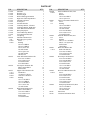
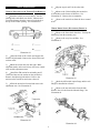
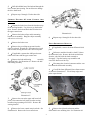
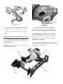
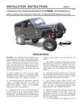
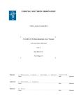
INSTALLATION INSTRUCTION
88146
Rev A
FOR RANCHO SUSPENSION SYSTEM RS6546: CHEVROLET SUBURBAN
READ ALL INSTRUCTIONS THOROUGHLY FROM START TO FINISH BEFORE BEGINNING INSTALLATION
IMPORTANT NOTES!
WARNING: This suspension system will enhance the
off-road performance of your vehicle. It will handle
differently, both on and off-road, from a factory
equipped passenger car or truck. Extreme care must be
used to prevent loss of control or vehicle rollover during
abrupt maneuvers. Failure to drive this vehicle safely
may result in serious injury or death to the driver and
passengers. ALWAYS WEAR your seat belts,
REDUCE your speed, and AVOID sharp turns and other
abrupt maneuvers.
C. Do not install a body lift kit with this suspension
system or interchange Rancho components with parts
from another manufacturer. Use the following Rancho
shock absorbers: Front shocks RS9268 or RS17337,
Rear shocks RS9274 or RS17346
A. DO NOT install suspension system RS6546 on
vehicles equipped with the
Autoride Suspension
Option.
E. Each hardware kit in this system contains fasteners
of high strength and specific size. Do not mix hardware
kits or substitute a fastener of lesser strength. See bolt
identification table on page 2.
B. Before installing this system, have the vehicle’s
alignment and frame checked by a certified technician.
The alignment must be within factory specifications and
the frame of the vehicle must be sound (no cracks,
damage or corrosion).
D. Do not chrome, cadmium, or zinc plate any of the
components in this system. To change the appearance
of components, enamel paint can be applied over the
original coating.
F. Compare the contents of this system with the parts
list in these instructions. If any parts are missing,
contact the Rancho Technical Department at 1-800-5746257.
G. Install all nuts and bolts with a flat washer. When
both SAE (small OD) and USS (large OD) washers are
used in a fastener assembly, place the USS washer
against the slotted hole and the SAE washer against the
round hole.
K. It is extremely important to replace torsion bars, CV
flanges, and front drive shaft/pinion relationships as
original. Be sure to mark left/right, front/rear, and
indexing of mating parts before disassembly. A paint
marker or light colored nail polish is handy for this.
H. Apply a drop of thread locking compound to all
bolts during installation. CAUTION: Thread locking
compound may irritate sensitive skin. Read warning
label on container before use.
L. Suspension components that use rubber or urethane
bushings should be tightened with the vehicle at normal
ride height. This will prevent premature failure of the
bushing and maintain ride comfort.
I. Unless otherwise specified, tighten all nuts and bolts
to the standard torque specifications shown in the table
below. USE A TORQUE WRENCH for accurate
measurements.
M. The required installation time for this system is
) at the
approximately 12 hours. Check off the box (
beginning of each step when you finish it. Then when
you stop during the installation, it will be easier to find
where you need to continue from.
J. Some of the service procedures require the use of
special tools designed for specific procedures. The
following tools and supplies are recommended for
proper installation of this system:
N. This suspension system was developed using the
following tire & wheel combination: 285/75 R16 tire,
16 x 8 wheel with 4.5 inches of wheel backspacing.
Before installing any other combination, consult your
local tire and wheel specialist. A 16-inch factory wheel
with more than 4.5 inches of backspacing cannot be
used with this suspension system.
Chevrolet Service Manual
Torsion Bar Unloading Tool J36202
Universal Steering Linkage Puller J24319
Ball Joint Separator J43631
Prevailing Torque Nuts (for steering linkage)
Die Grinder
Drill motor
Assorted Drills: 1/8" through 1/2"
Torque Wrench (250 FT-LB capacity)
1/2” Drive Ratchet and Sockets
Assorted Combination Wrenches
Heavy Duty Jack Stands
Wheel Chocks (wooden blocks)
Hydraulic Floor Jack
Center punch
File
Large "C" Clamps, Bench Vise and Adjustable Straps
Reciprocating Saw (to modify frame and differential)
Hammer
Wire Brush (to clean bracket mounting surfaces)
Silicone Spray Lubricant
Tape Measure
Safety Glasses (wear safety glasses at all times)
O. Important information for the end user is contained
in the consumer information pack. If you are installing
this system for someone else, display the information
pack by hanging it from the rear view mirror.
P. Thank you for purchasing the best suspension
system available. For the best installed system, follow
these instructions. If you do not have the tools or are
unsure of your abilities, have this system installed by a
certified technician. RANCHO SUSPENSION IS NOT
RESPONSIBLE FOR DAMAGE OR FAILURE
RESULTING FROM AN IMPROPER OR MODIFIED
INSTALLATION…
STANDARD BOLT TORQUE & IDENTIFICATION
Bolt Size
5/16
3/8
7/16
1/2
9/16
5/8
3/4
INCH SYSTEM
Grade 5
15 FT-LB
30 FT-LB
45 FT-LB
65 FT-LB
95 FT-LB
135 FT-LB
185 FT-LB
Grade 8
Bolt Size
20 FT-LB
35 FT-LB
60 FT-LB
90 FT-LB
130 FT-LB
175 FT-LB
280 FT-LB
M6
M8
M10
M12
M14
M16
M18
2
METRIC SYSTEM
Class 9.8
Class 10.9
5 FT-LB
18 FT-LB
32 FT-LB
55 FT-LB
85 FT-LB
130 FT-LB
170 FT-LB
9 FT-LB
23 FT-LB
45 FT-LB
75 FT-LB
120 FT-LB
165FT-LB
240FT-LB
Class 12.9
12 FT-LB
27 FT-LB
50 FT-LB
90 FT-LB
145 FT-LB
210 FT-LB
290 FT-LB
PARTS LIST
P/N
176126
176128
176129
176130
176131
176132
176135
176138
176190
176191
176192
176193
176194
176195
672
860174
1429
420041
520041
860175
860176
860177
176137
420042
420045
520041
860179
DESCRIPTION
Subframe
Knuckle, Left
Knuckle, Right
Differential Support Bracket
Right Axle Tube Drop Bracket
Subframe Aft Brace
Axle Spacer
Aft Brace Bracket
Link Drop Bracket, Left Rear
Link Drop Bracket, Right Rear
Track Bar Relocation Bracket
Bump Stop Spacer
Torsion Bar Drop Bracket
Sway Bar End Link, Rear
Coil Spring
Subframe Hardware Kit
Bump Stop (low profile)
Sleeve
Bushing
5/8-18x4.5 HHCS
5/8-18x5.5 HHCS
5/8-18 Stover Nut
5/8 SAE Washer
3/8-16 Nyloc Nut
3/8 SAE Washer
Thread Lock
Front differential Hardware Kit
9/16-12x1.75 HHCS
9/16-12 Stover Nut
9/16 SAE Washer
9/16 USS Washer
Axle Spacer Hardware Kit
M10-1.50x60 HHCS
SAE Washer
Support Tube Hardware Kit
Nut Bracket
.75x.095x2.73 Sleeve
1.00x.219x1.00 Sleeve
Bushing
1/2-13x1.25 HHCS
1/2-13x2.5 HHCS
1/2-13x4.00 HHCS
1/2-13 Stover Nut
1/2 SAE Washer
Differential Hardware Kit
M10-1.50x60 HHCS
7/16-14x3.0 HHCS
7/16-14 Stover Nut
SAE Washer
7/16 SAE Washer
QTY.
1
1
1
1
1
2
2
2
1
1
1
2
2
2
2
1
2
1
2
2
2
4
8
2
2
3
1
2
2
2
2
1
12
12
1
2
4
2
8
2
2
4
6
12
1
4
1
1
4
2
P/N
860180
420044
860411
485
552
860412
448
545
860413
170014
860414
860415
420052
860416
88146
94140
3
DESCRIPTION
End Link Hardware Kit, Front
Sleeve
Retainer
3/8-16x14.0 HHCS
3/8-16 Nyloc Nut
T Bar Crossmember Hardware Kit
Sleeve
Bushing
3/8-16x1.00 HHCS
3/8-16 Stover Nut
3/8 SAE Washer
9/16-12x3.00 HHCS
9/16-12 Stover Nut
9/16 SAE Washer
End Link Hardware Kit, Rear
Sleeve
Bushing
M12 x 1.75 x 70 HHCS
M12 X 1.75 Nyloc Nut
SAE Washer
USS Washer
Brake Line Bracket Kit
Brake Line Bracket
5/16-18x1.25 HHCS
5/16-18 Top lock Nut
5/16 SAE Washer
Rear Drop Link Hardware
9/16-12x3.50 HHCS
9/16-12x4.00 HHCS
9/16-12 Stover Nut
9/16 SAE Washer
1/2-13x1.25 HHCS
1/2-13 Stover Nut
1/2 SAE Washer
Rear Track Bar Hardware Kit
Sleeve
9/16-12x4.00 HHCS
9/16-12 Stover Nut
9/16 SAE Washer
7/16-14x1.25 HHCS
7/16-14 Stover Nut
7/16 SAE Washer
Bump Stop Hardware Kit, Rear
3/8-16x1.50 HHCS
3/8-16 Stover Nut
3/8 SAE Washer
Instructions
Consumer Information Pack
QTY.
1
2
8
2
2
1
2
4
4
4
8
2
2
4
1
4
4
2
2
2
2
1
1
1
1
2
1
2
2
4
8
2
2
4
1
1
1
1
2
1
1
2
1
4
4
8
1
1
6)
FRONT SUSPENSION
Repeat steps 4 and 5 for the other side.
Remove the 2 bolts holding the torsion bar
7)
crossmember to the frame rail brackets. See
illustration #2. Remove the crossmember.
VEHICLE PREPARATION & TORSION BAR REMOVAL
1)
Park the vehicle on a level surface. Set the
parking brake and chock rear wheels. Measure and
record the distance from the center of each wheel to
the top of the fender opening. See illustration #1.
Remove the torsion bars from the lower control
8)
arms.
WHEEL DRIVE SHAFT (HALFSHAFT) REMOVAL
1)
Remove the front shock absorbers. Unsnap the
bump stop from the mounting cup.
Remove the sway bar end links. See
2)
illustration #3.
Illustration #1
Raise the front of the vehicle and support the
2)
frame with jackstands. Remove the front wheels and
set them aside.
3)
Mark the torsion bars left and right. Make
alignment marks on the torsion bars, the lower control
arms, and the adjustment arms.
Install the GM torsion bar unloading tool (J
4)
36202) and increase the tension on the torsion bar.
Remove the adjusting bolt and nut. Relieve the
tension on the torsion bar and remove the tool.
Illustration #3
Mark the differential output flange and the axle
3)
flange for installation reference.
5)
Slide the torsion bar forward and remove the
adjustment arm. See illustration #2.
Remove the nut and washer from the hub.
4)
Remove the six bolts from the inboard flange. See
illustration #4.
Illustration #2
Illustration #4
4
5)
Pull the halfshaft out of the hub and through the
lower control arm opening. Be careful not to damage
the drive shaft boots.
6)
Repeat steps 3 through 5 for the other side.
STEERING KNUCKLE & L OWER CONTROL ARM
REMOVAL
1)
Separate the brake hose from the bracket on top
of the steering knuckle. Use pliers to pry the bracket
open. Remove the bolt and brake hose bracket from
the upper control arm.
Illustration #6
Remove the brake caliper and its mounting
2)
bracket as an assembly. Hang the caliper assembly
with wire or a tie wrap.
3)
9)
Remove the brake rotor.
Repeat steps 1 through 8 for the other side.
FRONT DIFFERENTIAL REMOVAL
Remove the prevailing torque nut from the
4)
outer tie rod stud. Discard nut. Disconnect the tie rod
end from the steering knuckle with a universal puller.
1)
If applicable, remove the front differential skid
plate.
Reference mark the front drive shaft U-joint to
2)
the differential yoke. Remove the bolts and retainers
from the yoke and slide the shaft rearward to
disengage. Tape the bearing cap assemblies and
secure the shaft out of the way.
If applicable, separate the ABS speed sensor
5)
cable at the frame and the upper control arm.
Remove the hub and bearing
assembly
6)
mounting bolts. See illustration #5. Remove the hub
and bearing assembly.
Disconnect the electrical connector and the vent
3)
hose from the differential assembly.
Cut off the front differential lower frame mount
4)
as shown in illustration #7. File all sharp edges and
paint exposed metal.
Illustration #5
Remove the nuts at the upper and lower ball
7)
joints. Disconnect the ball joints from the steering
knuckle using separating tool J43631. Remove the
steering knuckle.
Illustration #7
Remove the lower control arm pivot bolts. See
8)
illustration #6. Remove the lower control arm.
Remove the right axle tube nuts and the
5)
differential lower mounting bolt. See illustration #8.
5
Illustration #8
Illustration #9
Support the front differential assembly with a
6)
floor jack. Remove the upper mounting nut and bolt.
Install bushings 520041 into differential
2)
support bracket 176130. Apply silicon lubricant and
press sleeve 420041 through the installed bushings.
Remove the differential assembly from the
7)
vehicle.
Attach bracket assembly 176130 to the front
3)
differential as shown in illustration #10. Use the
hardware from kit 860179. Tighten to specifications.
FRONT DIFFERENTIAL & SUBFRAME INSTALLATION
NOTE: Gear oil may leak from the case when the
original bolts are removed.
1)
Cut off the upper mount (1/4" from the case)
and a section of the fins from the front differential.
See illustration #9.
Loosely attach drop bracket 176131 (as shown
4)
in illustration #10) to the differential axle tube with the
9/16" hardware from kit 860175.
CAUTION: When modifying the front differential, do
not cut into the case itself.
Illustration #10
6
5)
Attach the front differential assembly to the
subframe (176126) with the original hardware.
Tighten the nuts and bolts to 75 ft. lbs.
Attach the low profile bump stops (1429) to the
6)
subframe with the 3/8” hardware from kit 860174.
Using a piece of 1/2” plywood, support the
7)
subframe and differential assembly with a floor jack.
Raise the subframe up into the lower control
8)
arm frame brackets. Attach the subframe to the
brackets with the original hardware. Tighten the
subframe to bracket bolts to 107 ft. lbs.
Attach the right axle tube bracket 176131 to the
9)
frame bracket with the original hardware. Tighten all
bracket mounting nuts and bolts to 75 ft. lb.
Illustration #11
Place axle spacer 176135 against the
6)
differential flange. Place the axle flange against the
spacer. Align the flange marks and attach the axle to
the differential with the hardware from kit 860176. Be
sure to apply thread lock to the bolts. Tighten the
flange bolts to 58 ft. lbs.
NOTE: Verify that the left side of the front
differential does not contact the rear frame bracket of
the lower control arm. If necessary, cut off more of
the fins from the differential case (illustration #9).
FAILURE TO PROVIDE CLEARANCE COULD
CAUSE DAMAGE TO THE DIFFERENTIAL
AND AXLE ASSEMBLY.
Install the brake rotor. Reattach the front
7)
caliper with the original mounting bolts. Be sure to
clean the bolt threads and apply thread lock. Tighten
the caliper mounting bolts to 129 ft. lbs.
Reconnect the vent hose and electrical
10)
connector. Align marks and reconnect the front drive
shaft to the differential.
Place a drift or large screwdriver through the
8)
caliper to prevent the drive axle from turning. See
illustration #12.
STEERING KNUCKLE & HALFSHAFT INSTALLATION
1)
Loosely attach the left lower control arm to the
subframe with the 5/8” hardware from kit 860174.
Connect left steering knuckle 176128 to the
2)
lower and upper control arm ball joints. Tighten the
nut on the lower ball joint stud to 74 ft. lbs., and the
nut on the upper ball joint stud to 37 ft. lbs.
Apply thread lock and attach the hub and
3)
bearing assembly to the left steering knuckle with the
original hardware. See illustration #11.. Tighten the
mounting bolts to 133 ft. lbs.
Illustration #12
Loosen the tie rod end jam nut and thread the
4)
tie rod end inward two complete turns. Retighten the
jam nut and attach the tie rod end to the new knuckle.
Tighten the new prevailing torque nut to 33 ft. lbs.
Tighten the axle hub nut to 165 ft. lbs. Remove
9)
the drift from the rotor.
Slide the brake hose clamp down and attach it
10)
to the top hole in the back of the steering knuckle. Use
a clamp bolt from the original knuckle.
If applicable, reconnect the ABS cable. Attach
11)
the ABS cable to the knuckle and upper control arm
with tie wraps. See illustration #13.
Insert the wheel drive shaft (halfshaft) into the
5)
knuckle hub. Install the shaft washer and nut.
NOTE: Do not lubricate the wheel drive shaft splines
and the knuckle with grease.
7
Illustration #14
Illustration #13
12)
Repeat steps 1 through 11 for the other side.
AFT BRACE INSTALLATION
Attach the sway bar to the lower control arm
13)
with the new end link assemblies (from kit 860180)
and the original bushings. See illustration #14. Insert
the 3/8” x 14” bolt from the top.
1)
Lubricate two bushings (520041) and one
sleeve (420042), from kit 860177, with a silicon spray.
Press the bushings and sleeve into aft brace 176132 as
shown in illustration 15.
14)
Install new Rancho shock absorbers.
3)
Illustration #15
Loosely attach each aft brace assembly to the
rear of the subframe (176126) with the hardware from
Repeat step 1 to install the rest of the bushings
2)
and sleeves.
8
kit 860177.
If applicable, remove the transfer case skid
4)
plate.
To mount the driver side aft brace bracket, drill
5)
a 1/2” hole through the bottom of the transmission
crossmember. See illustration #15.
Insert nut bracket 176137 inside the
6)
crossmember as shown in illustration #15. Align the
bracket over the existing or previously drilled hole.
Apply thread lock and insert a 1.25” bolt with
7)
washer (from kit 860177) through the slotted hole in
bracket 176138. Attach the bracket to the
crossmember by threading the bolt into the nut
bracket. Do not tighten the bolt at this time.
8)
Repeat steps 6 and 7 for the other side.
Attach each aft brace to the crossmember
9)
brackets with the hardware from kit 860177. See
illustration #15.
Illustration #16
Insert two bushings and a sleeve (from kit
6)
860411) into each new torsion bar drop bracket.
10)
Tighten the aft brace mounting bolts to 80 FTLBS then the bracket to crossmember bolts to 65 FTLBS.
Attach the drop brackets to the crossmember
7)
with the original bolts.
If applicable, cut the corner of the skid plate to
11)
avoid contact with the aft brace bracket. Reinstall the
transfer case skid plate.
Attach the crossmember assembly to the frame
8)
brackets with the 9/16” and 3/8” hardware from kit
860411. Tighten the 3/8” bolts to 35 ft. lbs. then the
9/16” & original bolts to 70 ft. lbs.
TORSION BAR & DROP BRACKET INSTALLATION
1)
Place torsion bar drop bracket 176194 against
the frame rail directly below the crossmember bracket.
Temporarily install the 9/16” bolt from kit 860411.
See illustration #16.
Slide a torsion bar rearward through the
9)
crossmember while holding the adjustment arm in
proper position. Verify that the reference mark on the
adjustment arm matches the mark on the end of the
torsion bar.
Mark and center punch the 2 holes on the
2)
bottom of the existing bracket.
10)
Install the torsion bar unloading tool and
increase the tension on the torsion bar.
Remove the bracket and drill a 7/16” hole at
3)
each of the marked locations.
11)
Reinstall the retaining plate and adjusting bolt.
Thread the adjusting bolt in until 1.6 inches of threads
are exposed below the retaining plate. Remove the
unloading tool.
4)
Repeat steps 1 through 3 for the other side.
Align marks and insert the left and right torsion
5)
bars into their respective lower control arms. Slide the
arms forward.
12)
Repeat steps 9 through 11 for other side.
Install front wheels and lower vehicle to
13)
ground. Tighten the lug nuts to 140 ft. lbs.
Tighten the lower control arm pivot bolts to
14)
107 ft. lbs.
REAR SUSPENSION
9
END LINK, SHOCK ABSORBER, & C OIL SPRING
REMOVAL
8)
Remove the nut and bolt holding the track bar
to the rear axle.
1)
Chock front wheels. Raise the rear of the
vehicle and support the frame with jack stands.
Remove the rear wheels.
Remove the bracket holding the brake line
9)
junction block to the rear differential. Remove the two
bolts attaching the brake line to the left and right sides
of the rear axle.
Support the rear axle assembly with a floor
2)
jack.
Carefully lower the rear axle. Do not allow the
10)
axle to hang by any hoses or cables. Remove the coil
springs and insulators. See illustration #19.
Remove the end link nut and bolt from the
3)
frame bracket. Remove the end link nut from the ball
stud. See illustration #17.
Illustration #19
Illustration #17
4)
Remove the end link.
5)
Repeat steps 3 and 4 for the other side.
LINK DROP BRACKET INSTALLATION
1)
Starting with the driver side, remove the nuts
and bolts attaching the upper and lower links to the
frame. See illustration #20. Do not detach the links
from the passenger side.
Remove the upper shock absorber nut and bolt.
6)
Remove the lower shock absorber nut and bolt. See
illustration #18. Remove the shock absorber.
7)
Illustration #20
Illustration #18
Repeat step 6 for the other side.
10
3)
Insert left link drop bracket 176190 into the
frame brackets. See illustration #22. Temporarily
attach the bracket to the frame with the original bolts.
2)
Disconnect the left side brake cable from the
equalizer. Remove the cable from the mounting
bracket by depressing the locking tabs.
Mark and center punch the new 1/2” hole
4)
location on the bottom of the original lower link
bracket.
Remove the drop bracket and drill a 1/2” hole at
5)
the marked location.
Reattach drop bracket 176190 to the frame with
6)
the original hardware. Install the 1/2” hardware from
kit 860414. Tighten the 1/2” nut and bolt to 65 ft. lbs.
and the original bolts to 80 ft. lbs.
Insert the brake cable through the hole in the
7)
new drop bracket and into the frame mount until the
locking tabs snap into place. See illustration #23.
Attach the cable end to the equalizer.
Illustration #21
Illustration #22
Attach the upper and lower links to drop bracket
8)
176190 with the 9/16” hardware from kit 860414. Do
not tighten the bolts until the vehicle is at normal ride
height.
9)
Repeat steps 1 through 8, excluding the brake
cable, to install drop bracket 176191 on the passenger
side.
11
3)
Reattach the brake line to the rear axle with the
two original bolts.
COIL SPRING & SHOCK ABSORBER INSTALLATION
1)
Place new coil springs (672) with original
insulators on the rear axle. Raise the axle and guide
the springs into the frame pockets.
TRACK BAR BRACKET INSTALLATION
Attach new Rancho shock absorbers to the
2)
upper and lower mounts.
1)
Attach track bar bracket 176192 to the track bar
with the original hardware. Insert sleeve 420052 and
attach the new track bar bracket to the original as
shown in illustration #25. Use the 9/16” hardware
from kit 860415.
Illustration #23
Illustration #25
Drill a 7/16” hole through the axle bracket at the
2)
location shown in illustration #26. Install the
additional 7/16” hardware from kit 860415.
BRAKE LINE BRACKET INSTALLATION
1)
Attach the new brake line bracket 170014 to the
rear differential with the original bracket bolt. See
illustration #24.
Illustration #26
Tighten the 9/16” bolt to 77 ft. lbs. and the
3)
7/16” bolt to 45 ft. lbs. Do not tighten the original
track bar bolt until the vehicle is at normal ride height.
Illustration #24
Carefully reshape the brake line and attach the
2)
junction block to the top of bracket 170014. Use the
5/16” hardware from kit 860143.
12
BUMP STOP SPACER INSTALLATION
SWAY BAR END LINK ASSEMBLY & INSTALLATION
1)
Place bump stop spacer 176193 on top of the
lower link axle bracket. See illustration #29. Align
the rear hole in the new bracket with the existing hole.
Mark the additional mounting hole location.
1)
Apply silicone lubricant and press bushing 545
into sway bar end link 176195. See illustration #27.
Apply silicone lubricant and press sleeve 448 into the
installed bushing.
Illustration #27
Illustration #29
Repeat step 1 to install the rest of the bushings
2)
and sleeves.
Remove the spacer and drill a 3/8” hole at the
2)
marked location.
Attach the end link assembly to the frame
3)
bracket with the original bolt. Attach the sway bar to
the end link with the 12mm hardware from kit 860412.
See illustration #28.
Attach bump stop spacer 176193 to the axle
3)
bracket with the 3/8” hardware from kit 860416.
4)
Repeat steps 1 through 3 for the other side.
Illustration #28
13
2)
Turn the front wheels completely left then
right. Verify adequate tire, wheel, and brake hose
clearance. Inspect steering and suspension for
tightness and proper operation.
4)
Repeat step 3 for the other side. Do not tighten
the end link bolts until the vehicle is at normal ride
height.
Install rear wheels and lower vehicle to ground.
5)
Tighten lug nuts to 140 ft. lbs.
Readjust headlamps. Have vehicle Aligned at a
3)
certified alignment facility.
Tighten the end link bolts to 24 ft. lbs. Tighten
6)
the track bar bolt to 77 ft. lbs. Tighten the upper link
arm bolts to 77 ft. lbs and the lower link arm bolts to
89 ft. lbs.
Recommended Alignment Specifications
Caster (degrees): 4.5° 1.0°
Camber (degrees): 0° - .3°
Sum Toe In (degrees): .1° .2°
FINAL CHECKS & ADJUSTMENTS
Jounce suspension and move the vehicle to
1)
normalize ride height. Verify that the front spindle to
fender height is 25.5" and that both sides are equal. If
necessary, reinstall GM tool J 36202 and adjust the
tension on the torsion bars to correct the height.
Notes:
RANCHO INDUSTRIES USA LIMITED WARRANTY
14
ABOUT OUR WARRANTY
Rancho Industries USA, warrants the listed products for the listed time
period and/or mileage to the original retail purchaser against defect and
wear-out when used on passenger cars and light trucks under normal
operating conditions. The warranty does not apply to Rancho products
which have been improperly applied or installed. The consumer will be
responsible for removing from the vehicle and returning any defective
item(s), transportation costs prepaid, to the dealer from which it was
purchased or a Rancho Authorized Installer, and for reinstallation of the part
upon return. A copy of the sales receipt is required for all warranty
adjustments. Rancho Industries will, without charge, repair or replace at its
option, defective products or component part(s).
Limited 2 year, 24,000 mile warranty on these Rancho products. Rancho
Industries warrants each new RS4000, Air Rancho shock and RC9000
Remote Control System against factory defects in material and
workmanship (except for finish, including shock boot) for the first to occur of
2 years or 24,000 miles after the date of purchase.
In the case that the customer is unable to return to the original place of
purchase or an Authorized Installer, the consumer may contact Rancho
Industries at 1-800-574-6257 to obtain a Return Authorization Number prior
to shipping. The consumer will be responsible for removing from the vehicle
and returning any defective item(s), transportation cost pre-paid, to the
following address: 1 International Drive, Monroe MI. 48161. A copy of the
sales receipt is required for any warranty adjustments. Rancho Industries
will, without charge, repair or replace at its option, defective products or
component part(s). Such item(s) will be returned with transportation costs
prepaid within the United States from Rancho Industries. The customer will
be responsible for reinstallation.
THIS LIMITED WARRANTY DOES NOT COVER THE FOLLOWING:
• Any component that has been modified, customized, or improperly
installed
• Any part that is obsolete and is no longer available or supplied by
Rancho
SUSPENSION COMPONENTS LIMITED LIFETIME WARRANTY
Limited lifetime warranty on all of Rancho’s suspension products. Rancho
Industries warrants each new Suspension Component against factory
defects in material and workmanship (except finish) for as long as the
original retail purchaser owns the vehicle on which the products were
originally installed.
RANCHO GEAR
Disclaimer Statement
Grille Guards, Side Steps, Skid Plates and Taillight Guards are designed as
decorative accessories to enhance the styling of the vehicle and are not
intended as collision protection devices. These products offer no significant
incremental collision protection beyond that provided by the original vehicle
design as produced by the vehicle manufacturer. Buyer assumes all risk
and liability whatsoever resulting from the installation and use of Rancho
Gear products. Rancho assumes no liability for injury, collision or other road
hazard. These products are not a substitute for safe and careful driving.
Exclusions from this warranty are sales outside of the United States, the
finish, any condition(s) caused by abnormal use or service, and productspecific limitations, if any, listed below.
THE LOSS OF USE OF THE PRODUCT, LOSS OF TIME,
INCONVENIENCE, COMMERCIAL LOSS OR CONSEQUENTIAL
DAMAGES ARE NOT COVERED. RANCHO INDUSTRIES RESERVES
THE RIGHT TO CHANGE THE DESIGN OF ANY PRODUCT WITHOUT
ASSUMING ANY OBLIGATION TO MODIFY ANY PRODUCT
PREVIOUSLY MANUFACTURED.
Vehicles equipped with supplemental restraint systems (air bags) that are
deployed by impact rather than a sudden velocity decrease should not be
modified or altered with any aftermarket grill guard or brush bar. Such
modification could alter the deployment of the airbag(s) in the event of a
frontal impact, collision or other road hazard.
THIS WARRANTY GIVES YOU SPECIFIC LEGAL RIGHTS AND YOU MAY
ALSO HAVE OTHER RIGHTS WHICH MAY VARY FROM STATE TO
STATE. SOME STATES DO NOT ALLOW LIMITATIONS ON HOW LONG
AN IMPLIED WARRANTY LASTS OR ALLOW THE EXCLUSION OR
LIMITATION OF INCIDENTAL OR CONSEQUENTIAL DAMAGES, THE
ABOVE LIMITATION OR EXCLUSION MAY NOT APPLY TO YOU.
Limited 5 Year Warranty
Limited 5 year warranty on Rancho Gear products. Rancho Industries
warrants each new Grille Guard, Side Step, Taillight Guard and Skid Plate
against factory defects in material and workmanship (except finish) for 5
years after the date of purchase.
RIGHTS RESERVED
Rancho Industries reserves the right to make changes in design, material
and specifications or to make product changes as deemed necessary
without prior notice. Obligations or liabilities will not be assumed with
respect to similar products previously advertised.
THERE ARE NO WARRANTIES, EXPRESSED OR IMPLIED INCLUDING
ANY IMPLIED WARRANTIES OF MERCHANTABILITY AND FITNESS,
WHICH EXTEND BEYOND THIS WARRANTY PERIOD. THERE ARE NO
WARRANTIES THAT EXTEND BEYOND THE FACE HEREOF. SELLER
DISCLAIMS IMPLIED WARRANTY OF MERCHANTABILITY.
PRINTING ERRORS
Every effort has been made to avoid printing errors in our literature.
However, if there are any specification or application errors, we must
disclaim responsibility.
THIS WARRANTY SHALL NOT APPLY TO ANY RANCHO PRODUCT
WHICH HAS BEEN MODIFIED, CUSTOMIZED OR IMPROPERLY
INSTALLED. WARRANTY DOES NOT APPLY TO ANY RANCHO
COMPONENTS USED FOR RACING PURPOSED, OR RACE TYPE
ACTIVITIES. WARRANTY DOES NOT APPLY TO ANY RANCHO
INDUSTRIES RACING PRODUCTS.
The product, time periods and/or mileage under this warranty are as follows:
RS5000 / RS5600 / RS9000 / RSX
LIMITED LIFETIME WARRANTY
Limited lifetime warranty on these Rancho shock absorbers. Rancho
Industries warrants each new shock against factory defects in material and
workmanship (except for finish, including the shock boot) for as long as the
original retail purchaser owns the vehicle on which the units were originally
installed.
RC9000 REMOTE CONTROL
LIMITED 2 YEAR, 24,000 MILE WARRANTY
15
This document was created with Win2PDF available at http://www.daneprairie.com.
The unregistered version of Win2PDF is for evaluation or non-commercial use only.