1
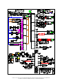
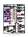
Manual Addendum
HU-80-1625
Supersedes 1635 Manual
PAGE 2 of 17 HU-80-1625 GAS-FIRED HUMIDAIRE AUSTRALIAN KING MESA MANUAL ADDENDUM
© SAMUEL JACKSON, INCORPORATED 2012 ALL RIGHTS RESERVED
TABLE OF CONTENTS
Warnings ...................................................................................... 5
Safety Features ............................................................................. 6
Special Safety Features ................................................................ 7
Airflow Switch and Fan Interlock ............................................... 8
Errors and Alarms ........................................................................ 9
Default Settings .......................................................................... 10
Electrical Wiring With Honeywell 7898 Flame Control ........... 11
Electrical Wiring With Siemens LFL Flame Control ................ 12
Honeywell 7898 to Siemens LFL1 Conversion Steps ............... 13
External Electrical Connections ................................................ 14
Gas Train Layout ...................................................................... 16
PAGE 3 of 17 HU-80-1625 GAS-FIRED HUMIDAIRE AUSTRALIAN KING MESA MANUAL ADDENDUM
© SAMUEL JACKSON, INCORPORATED 2012 ALL RIGHTS RESERVED
We appreciate your business and hope you enjoy your
Samuel Jackson King Mesa Gas-Fired Humidaire Unit
This manual contains information on the installation, startup, and operation of your Humidaire
Unit. Included is information on:
•
•
•
•
•
•
Humidaire operation.
Electrical installation.
Gas piping and supply.
Water supply and drainage.
Humidaire Unit dimensions.
Maintenance and troubleshooting.
When taking delivery of your new Humidaire Unit, take a moment to familiarize yourself with
the location of the less obvious items in the shipment. This service manual is normally shipped in
the BOX OF CONTROL PARTS. Included in this box are the air temperature thermocouple and
shielded cable thermocouple hookup wire. If your Humidaire Unit will be used to add moisture to
lint cotton a 14900A Lint Flue Scanner will also be included in this box.
We suggest that you check the contents of the box of control parts and then store them in a safe
place until installation time. This will help prevent some of the items from being misplaced or
being used for other jobs. Humidaire Unit installation will then go smoothly with no delays
waiting or looking for missing parts.
If the Humidaire Unit is part of a Samuel Jackson Conditioning Hopper Moisture System or a
Steamroller System, more detailed information for your system will be shipped to you under
separate cover.
IS STARTUP ASSISTANCE PROVIDED?
Depending upon your location, a startup and inspection service may be provided with your new
Humidaire Unit free of charge by Samuel Jackson, Inc. Please contact us to make arrangements
or for questions regarding startup services.
In the future when you require service, technical support, or parts please contact us by phone, fax,
or email. Our engineers and service people are available to assist you in obtaining the best
performance from your Samuel Jackson, Inc. products.
Again, thanks for choosing a Samuel Jackson King Mesa
Gas-Fired Humidaire Unit!
SAMUEL JACKSON, INCORPORATED
3900 UPLAND AVENUE LUBBOCK, TEXAS 79407
TELEPHONE +1-806-795-5218 OR 800-862-9966
TELEFAX +1-806-795-8240
Email: [email protected]
Internet: www.samjackson.com
PAGE 4 of 17 HU-80-1625 GAS-FIRED HUMIDAIRE AUSTRALIAN KING MESA MANUAL ADDENDUM
© SAMUEL JACKSON, INCORPORATED 2012 ALL RIGHTS RESERVED
READ THIS CAREFULLY BEFORE OPERATING
THIS SAMUEL JACKSON PRODUCT!
The Samuel Jackson product line consists of sophisticated technology capable of greatly enhancing a gin’s
productivity and efficiency. Improper use of these products could adversely affect those very same factors
and potentially cause injury to gin personnel. For this reason, we include an extensive manual with every
product. These manuals outline the proper and safe operating procedure for their respective product. Do not
operate any Samuel Jackson product without first reading the entire manual and all accompanying
information.
Sometimes there are updates added at the customer’s discretion to products already in the field. We always
refer customers to our website, www.samjackson.com for the latest product information. The latest manual
can be downloaded or printed from the website free of charge. In addition to printed literature, the website
includes training videos on several popular products. When available, these videos are highly
recommended for viewing before operating a respective product. If you do not have internet access, give us
a call and we will gladly send you the latest product information.
DANGER: Please read and understand all the warnings below before operating or maintaining a
Samuel Jackson product. If you do not understand, call Samuel Jackson at 806-795-5218 before
proceeding. Failure to do so could result in injury or even death. (Si usted no entiende, llamar a
Samuel Jackson en 806-795-5218 antes de proceder. La falta de hacer tan podía
dar lugar alesión o aún a muerte.)
Electrical.
Most Samuel Jackson products use supply voltage between 110 and 480 volts AC. These levels are
considered high voltage and are extremely dangerous. The ignition transformer voltage output is much
higher than this.
Fire.
Samuel Jackson Humidaire Units and Heaters are combustion-based products. They ignite and burn fuel
during operation. These products can reach very high temperatures inside and out. Allow combustion based
products 15 minutes to cool before attempting any work.
Automatic Flame Ignition.
Some Samuel Jackson Humidaire Units and Heaters use technology to ignite automatically. If you do not
see a flame, it does not mean that respective product is not in operation.
Access Doors.
Samuel Jackson products have access doors for added convenience of product maintenance. Access doors
must not be opened while the equipment is in operation. Access doors should also remain closed while any
connected equipment such as a fan or conveyor is in operation.
Moving Parts.
Many Samuel Jackson products have moving or rotating parts. These parts could form pinch points or grab
loose clothing or jewelry. Do not reach across or into any product while in operation.
Replacement Parts.
When repairing or maintaining this equipment, use only Samuel Jackson approved parts.
Do not work on any Samuel Jackson product without first following OSHA Lockout/Tagout procedures.
Confirmation by a licensed electrician that there is no electricity present is highly recommended. We
recommend using a Samuel Jackson Authorized Technician for all work Samuel Jackson products.
Additional safety information is located throughout this manual and should be read carefully before
operating this Samuel Jackson product. If you have any questions about how to properly operate a
Samuel Jackson product, please call 806-795-5218 before proceeding.
PAGE 5 of 17 HU-80-1625 GAS-FIRED HUMIDAIRE AUSTRALIAN KING MESA MANUAL ADDENDUM
© SAMUEL JACKSON, INCORPORATED 2012 ALL RIGHTS RESERVED
PAGE 6 of 17 HU-80-1625 GAS-FIRED HUMIDAIRE AUSTRALIAN KING MESA MANUAL ADDENDUM
© SAMUEL JACKSON, INCORPORATED 2012 ALL RIGHTS RESERVED
SPECIAL SAFETY FEATURES
OF
HU-80-1625 GAS- FIRED HUMIDAIRES
The HU-80-1625 has been specifically designed to meet AS 3814-2009. The HU-80-1625
is operationally the same as the HU-80-1635 except for combustion control. Combustion
control is handled by a Honeywell RM7898 control instead of a PLC. Due to the use of
the Honeywell 7898 combustion control instead of a PLC many of the diagnostics
described in the HU-80-1635 manual are not available in the HU-80-1625. The gas train
and electrical schematics included here supersede those found in the HU-80-1625
manual.
♦ A valve leak test is preformed at the beginning of each ignition sequence and again at
the end of each shutdown sequence.
♦ An airflow switch, which measures the difference in pressure, sensed by orifices
pointing upstream and downstream is interlocked with the Honeywell flame control.
♦ A fan interlock relay is interlocked with the Honeywell flame control. Ignition is not
possible if the main plant control system does not report the fan(s) are running.
♦ The gas high pressure and gas low pressure switches are a manual reset type.
♦ A timed air purge to achieve 5 air changes prior to opening of any gas valve(s).
♦ Upon ignition or flame failure the Honeywell RM7898 reports an alarm condition to
the Humidaire’s PLC that appears on both the Humidaire’s touch screen and the
Moisture Mirror touch screen (if equipped) alerting the operator to the fault.
♦ A high limit temperature switch for the moist air line using a Type-J thermocouple.
Connect Type-J thermocouple using thermocouple wire to the Omron high limit
temperature switch with white on terminal 1 and red on terminal 2.
PAGE 7 of 17 HU-80-1625 GAS-FIRED HUMIDAIRE AUSTRALIAN KING MESA MANUAL ADDENDUM
© SAMUEL JACKSON, INCORPORATED 2012 ALL RIGHTS RESERVED
AIR FLOW SWITCH AND FAN INTERLOCK
There are two airflow-sensing devices employed by the HU-80-1625 Humidaire control
system. The mechanical airflow switch is connected to the Honeywell RM7898
combustion control unit per AS-3814. An additional analog sensor is connected to the
Humidaire PLC to allow for simplified diagnostics of airflow problems. Only the
mechanical airflow switch has direct control within the combustion safety device.
In cotton gins it is typical for the fans that provide the combustion air for the Humidaire
to be controlled by a master plant control system. A fan interlock relay is provided and
MUST BE USED for safe operation of the Humidaire. This interlock is connected to the
Honeywell RM7898 flame control and no ignition can occur unless it is satisfied.
PAGE 8 of 17 HU-80-1625 GAS-FIRED HUMIDAIRE AUSTRALIAN KING MESA MANUAL ADDENDUM
© SAMUEL JACKSON, INCORPORATED 2012 ALL RIGHTS RESERVED
ERRORS AND ALARMS EXPLANATION
HU-80-1625 GAS-FIRED HUMIDAIRE
ERROR 157
EXTERNAL FLAME CONTROL ALARM: The Honeywell RM7898 combustion control
has detected an unsafe condition and shut down the burner. Check the display on the
Honeywell RM7898 for more details. If the Honeywell RM7898 has been replaced with a
substitute flame control system check the alarm or fault notification of that device.
Some alarms are caused by high or low gas pressure. These switches are NOT directly
monitored by the PLC and will cause a generic flame failure alarm. Verify that these
switches have been reset by pressing the red reset button on each switch. If the orange
light is present within the switch enclosure, then the switch is operational. If not, then the
switch will need to be reset or the gas pressure is not within bounds.
PAGE 9 of 17 HU-80-1625 GAS-FIRED HUMIDAIRE AUSTRALIAN KING MESA MANUAL ADDENDUM
© SAMUEL JACKSON, INCORPORATED 2012 ALL RIGHTS RESERVED
Sequence dial – FAULT and LOCKOUT indication
2 1
P
P
P
P
P
P
P
1
1
2 1
2 1
2 1
2
P
9/12
Siemens Building Technologies
HVAC Products
PAGE 10 of 17 HU-80-1625 GAS-FIRED HUMIDAIRE AUSTRALIAN KING MESA MANUAL ADDENDUM
© SAMUEL JACKSON, INCORPORATED 2012 ALL RIGHTS RESERVED
CC1N7451en
11.15.2004
DEFAULT SETTINGS
HONEYWELL 7898 SETTINGS:
Password: 78
VP when: BOTH
VP time: 00:15
Post time: 00:00
#1 Resistor: Clipped
#2 Resistor: Clipped
#3 Resistor: Intact
GAS LOW PRESSURE SWITCH (located on front of gas block): 50 mbar
GAS HIGH PRESSURE SWITCH (located on right of gas block): 350 mbar
VALVE PROVING SWITCH (located on back of gas block): 45 inch wc
Omron HIGH TEMPERATURE LIMIT SWITCH: 300 °F
PAGE 11 of 17 HU-80-1625 GAS-FIRED HUMIDAIRE AUSTRALIAN KING MESA MANUAL ADDENDUM
© SAMUEL JACKSON, INCORPORATED 2012 ALL RIGHTS RESERVED
PAGE 12 of 17 HU-80-1625 GAS-FIRED HUMIDAIRE AUSTRALIAN KING MESA MANUAL ADDENDUM
© SAMUEL JACKSON, INCORPORATED 2012 ALL RIGHTS RESERVED
PAGE 13 of 17 HU-80-1625 GAS-FIRED HUMIDAIRE AUSTRALIAN KING MESA MANUAL ADDENDUM
© SAMUEL JACKSON, INCORPORATED 2012 ALL RIGHTS RESERVED
HONEYWELL 7898 TO SIEMENS LFL1 WIRING CONVERSION
120vAC
Neutral
Ground
Alarm
Valve Proving Pressure Switch
Flame Rod
Pilot Valve(s)
SSOV1
SSOV2
Ignition Transformer
Limits & Call for Heat
Proof of Closure Switch(s)
3-Way AFS Proving Solenoid
Limits & Call for Heat:
Honeywell 7898
Siemens LFL1
5
1
L2
2
G
G & 22
3
3
16
NA, Cut & Cap Wire
11 or F
24
8
17
9
19
21
19
10
16
See details below
See details below
See details below
1) Remove wire between AU13 and term 8 on the fan interlock relay.
2) Remove wire between AU3 and term 5 on the call for heat relay.
3) Remove wire between AU2 and term 4 on old high temp limit.
4) Remove wire between AU13 and term 5 on old high temp limit.
5) Remove wire between 3 and term 7 on old high temp limit.
6) Remove wire between 1 and term 8 on old high temp limit.
7) Remove TC wires from term 1 & 2 on old high temp limit.
8) Remove wire between AU3 & Air Flow Switch.
9) Remove wire between AU4 & Air Flow Switch.
10) Remove wire between AU4 & term 7 on the 7898.
11) Remove wire between AU5 & term 17 on the 7898.
12) Add wire from AU4 to term 8 on the fan interlock relay.
13) Add wire from AU4 to term 5 on the call for heat relay.
14) Connect white TC wire to term 6 on new high temp limit.
15) Connect red TC wire to term 7 on new high temp limit.
16) Add wire from 3 to term 1 & term 5 on new high temp limit.
17) Add wire from 1 to term 2 on new high temp limit.
18) Add wire from term 4 on new high temp limit to 13 on new high
temp limit relay.
17) Add wire from 1 to term 14 on new high temp limit relay.
18) Add wire from 30 to term 8 on new high temp limit relay.
19) Add wire from X3 to term 12 on new high temp limit relay.
20) Add wire from AU2 to term 5 on new high temp limit relay.
21) Add wire from AU3 to term 9 on new high temp limit relay.
22) Connect wire from AU5 to term 13 on new limits relay.
23) Connect wire from 1 to term 14 on new limits relay.
24) Connect term 5 on LFL to term 9 on new limits relay.
25) Connect term 4 on LFL to term 5 on new limits relay.
26) Connect term 4 on LFL to C on Air Flow Switch.
27) Connect term 14 on LFL to NO on Air Flow Switch.
28) Connect term 13 on LFL to NC on Air Flow Switch.
PAGE 14 of 17 HU-80-1625 GAS-FIRED HUMIDAIRE AUSTRALIAN KING MESA MANUAL ADDENDUM
© SAMUEL JACKSON, INCORPORATED 2012 ALL RIGHTS RESERVED
POC Switch:
3-Way AFS Proving:
1) Remove wire between AU6 and term 20 on the 7898.
2) Add wire from AU6 to term 13 on new POC relay.
3) Add wire from 1 to term 14 on new POC relay.
4) Add wire from term 13 on LFL to term 5 on new POC relay.
5) Add wire from term 12 on LFL to term 9 on new POC relay.
1) Add wire from term 6 on LFL to coil of solenoid.
2) Add wire from 1 to coil of solenoid.
3) Disconnect tube from AFS and insert into NO of solenoid.
4) Connect tube from C of solenoid to AFS.
5) Repeat steps 1-4 for second AFS tube.
Remove LFL Modulation: 1) Add wire(s) to jump LFL terms 8, 9, 10, & 11 together.
PAGE 15 of 17 HU-80-1625 GAS-FIRED HUMIDAIRE AUSTRALIAN KING MESA MANUAL ADDENDUM
© SAMUEL JACKSON, INCORPORATED 2012 ALL RIGHTS RESERVED
PAGE 16 of 17 HU-80-1625 GAS-FIRED HUMIDAIRE AUSTRALIAN KING MESA MANUAL ADDENDUM
© SAMUEL JACKSON, INCORPORATED 2012 ALL RIGHTS RESERVED
PAGE 17 of 17 HU-80-1625 GAS-FIRED HUMIDAIRE AUSTRALIAN KING MESA MANUAL ADDENDUM
© SAMUEL JACKSON, INCORPORATED 2012 ALL RIGHTS RESERVED